


DV318SI
Servicemanual

Catalog
Chapter One About Maintenance |
1 |
1.1 Safety precautions |
1 |
1.1.1 Power supply |
1 |
1.1.2 Precautions for antistatic |
1 |
1.1.3 Precautions for laser head |
1 |
1.1.4 About placement position |
2 |
1.2 Maintenance method |
2 |
1.2.1 Visualized method |
2 |
1.2.2 Electric resistance method |
2 |
1.2.3 Voltage method |
2 |
1.2.4 Current method |
2 |
1.2.5 Cutting method |
2 |
1.2.6 Element substitution method |
3 |
1.2.7 Comparison method |
3 |
1.3 Required device for maintenance |
3 |
Chapter Two Functions and Operation Instructions |
4 |
2.1 Features |
4 |
2.2 Control Button Locations and Explanations |
4 |
2.2.1 Front Panel Illustration |
4 |
2.2.2 Rear Panel Illustration |
5 |
2.2.3 Display Window Illustration |
5 |
2.2.4 Remote Control Illustration |
5 |
2.3 Accessories |
6 |
2.4 FUNCTION SETUP |
7 |
2.4.1 Function Setup |
7 |
2.4.2 Language |
7 |
2.4.3 Image |
7 |
2.4.4 Sound |
8 |
2.4.5 Playback |
8 |

2.4.6 Preference |
9 |
2.4.7 Parental control |
9 |
2.4.8 Initial setup |
9 |
2.4.9 Rest to defaults |
9 |
2.4.10 Exit |
9 |
2.5 Specifications |
9 |
Chapter Three Principleand Servicing |
11 |
Section One Principle ofthe Player |
11 |
3.1.1 Block diagram ofthe player |
11 |
3.1.2 PCB board blockdiagram of the player |
12 |
3.1.3 How to useIC |
13 |
Section Two Unit Circuit Principle |
14 |
3.2.1 Introduction to laserhead |
14 |
3.2.2 Servo circuit |
16 |
3.2.3 Open/close drive circuit |
18 |
3.2.4 Laser power controlcircuit |
18 |
3.2.5 CD/DVD conversion circuit |
19 |
3.2.6 Main axis controlcircuit |
20 |
3.2.7 Decode circuit |
21 |
3.2.8 Reset circuit |
22 |
3.2.9 Video circuit |
23 |
3.2.10 Audio circuit |
24 |
3.2.11Mute circuit |
25 |
3.2.12 Decode circuit voltageregulating |
26 |
3.2.13 Panel control circuit |
27 |
3.2.14 MIC circuit |
27 |
3.2.15 Power circuit |
27 |
Section Three ServicingCases |
29 |
3.3.1 Servicing cases |
29 |
3.3.2 Troubleshootingflow chart |
35 |
Section Four Waveform diagram |
47 |
Section Five Function Introductionto IC |
53 |
3.5.1 function introduction toMT1389 DE-EE |
53 |
3.5.2 function introduction to4558 |
61 |

3.5.3 function introduction toAT24C02 |
62 |
3.5.4 function introduction toTDA1308 |
63 |
3.5.5 function introduction toTNY275PN |
64 |
3.5.6 function introduction toAM5888S |
65 |
3.5.7 function introduction toAP6928 |
67 |
3.5.8 Function introduction toSDRAM |
68 |
3.5.9 Function introduction toFLASH |
69 |
3.5.10 Function introduction toTL431 |
70 |
3.5.11Function introduction to EL817 |
71 |
Chapter Four Disassembly andAssembly Process |
72 |
Chapter Cinque PCB board& Circuit diagram |
73 |
Section One PCB board |
73 |
Section Two circuit diagram |
80 |
Chapter six BOM List |
87 |
DV123SI Service Manual |
94 |
7.1.1 PCB composition figureof the player |
94 |
7.2.1 Panel control circuit |
95 |
7.2.2 MIC circuit |
95 |
7.3.1 PCB board |
96 |
7.3.2 circuit diagram |
100 |
Chapter One About Maintenance
1.1 Safety precautions
1.1.1 Power supply
When maintenance personnel are repairing DVD players, he should pay special attention to the power board with 220V AC and 330V DC which will cause hurt and damage to persons!
1.1.2 Precautions for antistatic
Movement and friction will both bring static electricity which causes serious damages to integrated IC. Though static charge is little, when a limited quantity of electric charge is added to largescaleintegrated IC, as the capacitance is very small in the meantime, now the integrated IC is very much easy to be struck through by static electricity or the performance will decrease. Thus static electricity prevention is of extraordinary importance. The following are several measures to prevent static electricity:
1.Use a piece of electric conduction metal with the length of about 2 metres to insert into the earth, and Fetch the lead wire from the top of the surplus metal and connect to the required static electricity device. The length and depth of the metal embedded under the earth should be determined according to the wettability of the local soil. For humid places, it may be shorter, and longer and deeper for dry places. If possible, it can be distributed and layed in terms of “#” shape.
2.On operating table-board, the antistatic table cushion should be covered and grounded.
3.All devices and equipments should be placed on the antistatic table cushion and grounded.
4.Maintenance personnel should wear antistatic wrist ring which should be grounded.
5.Places around the operating position should also be covered with electric conduction cushion or Painted with antistatic paint.
1.1.3 Precautions for laser head
1.Do not stare at laser head directly, for laser emission will occur when laser head is working, which will Hurt your eyes!
2.Do not use wiping water or alcohol to clean laser head, and you may use cotton swab.
-1 -
1.1.4 About placement position
1.Never place DVD player in positions with high temperature and humidity.
2.Avoid placing near high magnetic fields, such as loudspeaker or magnet.
3.Positions for placement should be stable and secure.
1.2 Maintenance method
1.2.1 Visualized method
Directly view whether abnormalities of collision, lack of element, joint welding, shedding welding, rosin joint, copper foil turning up, lead wire disconnection and elements burning up among pins of elements appear. Check power supply of the machine and then use hands to touch the casing of part of elements and check whether they are hot to judge the trouble spot. You should pay more attention when using this method to check in high voltage parts.
1.2.2 Electric resistance method
Set the multimeter in resistance position and test whether the numerical value of resistance of each point in the circuit has difference from the normal value to judge the trouble spot. But in the circuit the tested numerical value of resistance is not accurate, and the tested numerical value of integrated IC's pins can only be used for reference, so the elements should be broken down for test.
1.2.3 Voltage method
Voltage method is relatively convenient, quick and accurate. Set the multimeter in voltage position and test power supply voltage of the player and voltage of a certain point to judge the trouble spot according to the tested voltage variation.
1.2.4 Current method
Set the multimeter in current position and test current of the player of a certain point to judge the trouble spot. But when testing in current method, the multimeter should be series connected in the circuit, which makes this method too trivial and troublesome, so it is less frequently used in reality.
1.2.5 Cutting method
Cutting method should be combined with electric resistance method and voltage method to use. This method is mainly used in phenomena of short circuit and current leakage of the circuit. When cutting the input terminal voltage of a certain level, if voltage of the player rises again, it means that the trouble lies in this level.
- 2 -
1.2.6 Element substitution method
When some elements cannot be judged good or bad, substitution method may de adopted directly.
1.2.7 Comparison method
A same good PC board is usually used to test the correct voltage and waveform. Compared these data with those tested through fault PC board, the cause of troubles may be found.
Through the above maintenance method, theoretical knowledge and maintenance experience, all difficulties and troubles will be readily solved.
1.3 Required device for maintenance
 Digital oscillograph (
 100MHE)
 TV set
 SMD rework station
 Multimeter
 Soldering iron
 Pointed-month pincers
 Cutting nippers
 Forceps
 Electric screw driver
 Terminals connecting cord
 Headphone
 Microphone
- 3 -

Chapter Two
Functions and Operation Instructions
2.1 Features
Compatible Disc Types:
 Digital video playback:DVD-Video, Super VCD, VCD Compatibility.
 Digital audio playback:CD-DA and HDCD compatibility
 Fully compatible with compressed audio files such as Mp3and WMA.
 Digital graphic albums playback:kodak picture CD, JPEG compatibility.
Audio:
 Coaxial output for Dolby Digital/DTS/LPCM digital audio.
 Mixed audio output for amplifier or TV connection.
 Digital multi-channel decoders, providing Dolby Digital/DTS audio stream playing.
  MIC input for karaoke function.
Video:
 108 MHZ/12 bit video Digital/Analog converter.
 Composite, S-Video and RGB/SCART outputs for various types of connections.
 Capable of playing NTSC/PAL discs.
 Multiple dubbings, angles, subtitles support.
 Sharpness, gamma, brightness, contrast, hue, saturation adjustment.
Others:
 Compatible disc types:CD-R/CD-RW, DVD-R/DVD-RW, DVD+R/DVD+RW
 Russia, CIS and Baltic States adaptation interface and filenames, ID3-tags and CD-Text support simplifies device operation.
 "Memory” function enables to save the last point after stop playback.
 "Q-play” function provides direct playback and allows to skip commercial that is not possible to rewind.
 "Captrue” function allows to save any picture as background.
 "Virtual Keyboard” function provides more convenient DVD playback control.
 "Browser” function provides easy access to playback control.
 Automatic Screenaver function.
 Parental control function to protect children from watching inappropriate discs.
 Super wide range of operating power supplies(~110-250V, 50/60Hz), automatic short circuit protection.
2.2 Control Button Locations and Explanations
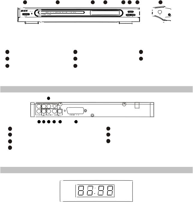
2.2.1 Front Panel Illustration
- 4 -
DV318SI
1 |
2 |
8 |
4 |
5 |
3 |
|
6 |
7 |
||||||
|
|
|
|
|
|
|
|
|
|
|
|
|
|
|
|
|
|
|
|
|
|
|
|
|
|
|
|
|
|
|
|
|
|
|
|
|
|
|
|
|
|
|
|
|
|
|
|
|
|
|
|
|
|
|
|
|
|
|
|
|
|
|
|
|
|
|
|
|
|
|
|
|
|
|
|
|
|
|
|
|
|
|
|
|
|
|
|
|
|
|
|
|
|
|
|
|
|
|
|
|
|
|
|
|
|
|
|
|
|
|
|
|
|
|
|
|
|
|
|
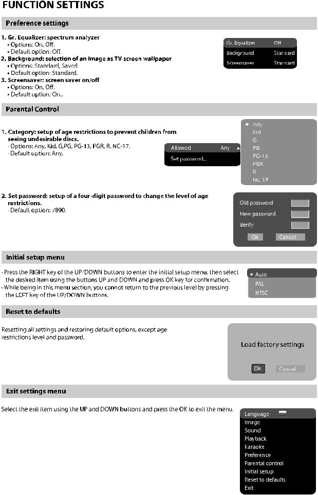
2.2.4 Remote Control Illustration
1 |
POWER switch |
4 |
2 |
Disc tray |
5 |
3 |
OPEN/CLOSE button |
6 |
Display window* |
7 |
MIC jack |
PLAY/PAUSE button |
8 |
IR sensor button |
STOP button |
|
|
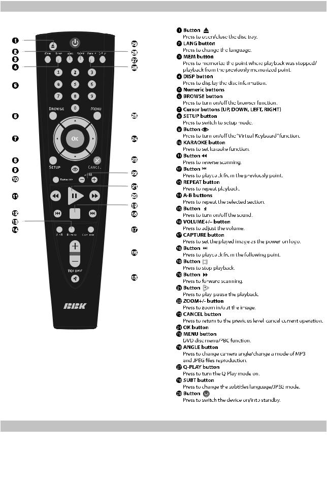
2.2.2 Rear Panel Illustration
7
|
2 |
1 |
4 |
3 |
6 |
5 |
|
1 |
Digital Audio CoaxialOut jack |
5 |
SCART Out jack |
||||
2 |
2CH Audio Outjacks |
|
|
6 |
Video |
||
3 |
S-Video |
|
|
|
|
7 |
Y/Cb/Cr |
4Video Out jack
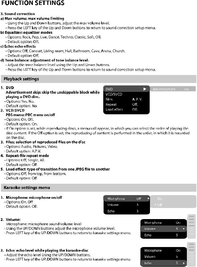
2.2.3Display Window Illustration
Playback time
- 5 -
2.2.4 Remote Control Illustration
2.3 Accessories
AUDIO/VIDEO CORD REMOTE
AAA SIIZEBATTERIES
WARRANTY CARD
USER MANUAL
KARAOKE DISC
1PCS
1PCS
2PCS
1PCS
1PCS
1PCS
- 6 -
- 7 -

- 8 -
- 9 -
- 10 -

- 11 -
Chapter Principle and Servicing
Section One Principle of the Player
3.1.1 Block diagram of the player
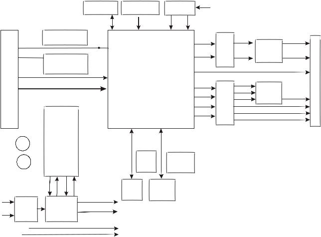
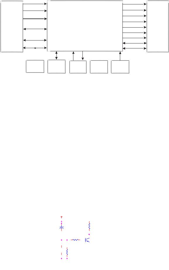
DV317SI is composed by decode circuit, servo circuit, audio circuit, video circuit, MIC circuit and power circuit, the blockdiagram of the playeris shown as inthe following figure 3.1.1.1:
SDRAM 64M |
FLASH16M |
MIC board |
MIC1 |
U8 |
U9 |
|
|
|
|
|
|
|
VR-DVD |
|
|
|
|
|
|
|
|
|
|
|
|
|
|
|
|
|
|
|
|
|
|
||||
|
|
|
VD-CD |
|
CD/DVD switch |
|
|
|
|
|
|
|
|
|
|
|
|
AL |
Audio |
L |
|||||||||
|
|
|
|
|
|
|
|
|
|
|
|
|
|
|
|
|
|
|
IOA |
|
|
|
|
|
|
amplifying |
|||
|
|
LD-DVD |
|
|
|
|
|
|
|
|
|
|
|
|
|
|
|
|
AR |
filtering |
|
||||||||
|
|
|
|
|
|
|
|
|
Ld02 |
|
|
|
|
|
R |
||||||||||||||
|
|
|
|
|
|
|
|
|
|
|
|
|
|
U13 |
|||||||||||||||
|
|
|
|
|
|
|
|
|
|
Laser power |
|
|
|
|
|
|
|
||||||||||||
-UP |
|
LD-CD |
|
|
|
|
Ld01 |
|
|
|
|
|
MT1389 D |
|
|
|
|
||||||||||||
|
|
|
control |
|
|
|
|
|
|
|
|
|
|
|
|
|
|||||||||||||
|
|
|
|
|
|
|
|
|
|
|
|
MDI |
|
|
|
|
|||||||||||||
|
|
|
|
|
|
|
|
|
|
|
|
|
|
|
|
|
|
|
|
|
|||||||||
PICK |
|
|
|
|
|
|
|
DVD:A/B/C/D/RFO |
|
U3 |
|
|
CVBS |
Video filtering catching |
SY |
||||||||||||||
|
|
|
|
|
|
|
CD:A/B/C/D/E/FRFO |
|
|
|
|
|
Y/G |
SC |
|||||||||||||||
|
|
|
|
|
|
|
|
|
|
|
|
CVBS |
|||||||||||||||||
|
|
|
|
|
|
|
|
|
|
|
|
|
|
|
|
|
|
|
|
|
|
|
|
|
|
||||
|
|
|
TK- |
|
|
|
|
|
|
|
|
|
|
|
|
|
|
|
|
|
|
|
CB/B |
B/U |
|||||
|
|
TK+ |
|
|
|
|
|
VIP4 |
|
|
|
|
|
|
|
|
|
CR/R |
R/V |
||||||||||
|
|
|
|
FC+ |
|
|
|
|
|
|
|
|
|
|
|
|
|
|
|
|
|
|
|
|
G/Y |
||||
|
|
|
|
FC- |
|
|
|
|
|
|
|
|
|
|
|
|
|
|
|
|
|
|
|
|
|
|
|||
|
|
|
|
|
|
|
|
|
|
Am5888 |
|
|
FOSO |
|
|
|
|
|
|
XI |
|
XO |
|
|
|||||
|
|
|
|
|
|
|
|
|
|
|
|
|
|
|
|
|
|
|
|
|
|||||||||
|
|
|
|
|
|
SL+ |
|
|
|
|
|
|
|
|
|
|
|
|
|
|
|
||||||||
Feed |
|
M |
|
|
|
U2 |
|
|
|
|
|
|
|
|
|
|
|
UREST |
SDA |
|
|
|
|
||||||
electric |
|
|
|
|
SL- |
|
|
|
|
|
FMSO |
|
|
|
|
|
SCL |
|
|
|
|
||||||||
machine |
|
|
|
|
|
|
|
|
|
|
DMSO |
|
|
|
|
|
|
|
|
|
|||||||||
Main |
|
|
M |
|
SP+ |
|
|
|
|
|
|
Reset |
|
|
|
|
|
||||||||||||
|
|
|
|
|
|
|
|
TRSO |
27M clock |
|
|
||||||||||||||||||
axis |
|
|
|
|
|
|
|
|
|
|
|||||||||||||||||||
electric |
|
|
SP- |
|
|
TRB2 |
|
|
|
|
|
|
|
|
|
|
|
|
|
|
|
|
|
|
|
||||
|
|
|
|
|
|
|
|
|
|
|
|
|
|
|
|
|
|
|
|
|
|
||||||||
|
|
|
|
|
|
|
|
|
|
|
|
|
|
|
|
|
|
|
|
|
|
|
|
|
|||||
machine |
|
|
|
|
|
|
|
|
|
|
|
|
|
|
|
|
|
|
|
|
|
|
|
|
|||||
|
|
|
|
|
|
TRB1 |
REGO2 |
Panel |
|
EEPROM |
|
|
|
|
|||||||||||||||
|
|
|
|
|
|
|
U11 |
|
|
|
|
||||||||||||||||||
|
|
|
|
|
|
|
|
|
|
|
|
|
|
|
|
||||||||||||||
|
|
|
|
|
|
|
|
|
|
REGO1 |
|
|
|
|
V18 |
|
|
24C02 |
|
|
|
|
|||||||
|
|
|
|
|
|
|
|
|
|
|
|
|
|
|
Dv33 |
|
|
|
|
|
|
|
|
||||||
ACIN |
Power |
|
|
Voltage |
|
|
|
|
|
|
|
|
|
|
|
|
|
||||||||||||
|
|
board |
|
|
regulating |
|
|
|
|
|
|
|
|
|
|
|
|
|
|
|
|
|
|
|
|||||
|
|
|
|
|
|
|
|
|
|
circuit |
|
|
|
|
+12V |
|
|
|
|
|
|
|
|
||||||
|
|
|
|
|
|
|
|
|
|
|
|
|
|
|
|
|
|
|
|
|
|
|
|||||||
|
|
|
|
|
|
|
|
|
|
|
|
|
|
|
|
-12V |
|
|
|
|
|
|
|
|
|||||
|
|
|
|
|
|
|
|
|
|
|
|
|
|
|
|
|
|
|
|
|
|
|
|
||||||
|
|
|
|
|
|
|
|
|
|
|
|
|
|
|
|
|
|
|
|
|
|
|
|
||||||
|
|
|
|
|
|
|
|
|
|
|
|
|
|
|
|
Figure 3.1.1.1 Block diagram ofthe player |
|
|
|||||||||||
Audio |
L# |
|
|
|
|
||
output |
R# |
terminal |
|
terminal |
|||
|
|||
SPDIF |
output |
||
S-video |
|
||
Terminal |
VIEDO# |
SCART |
|
|
|||
Video output |
|
||
|
PB# |
|
|
PR#
Y#
- 11 -
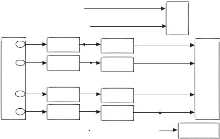
3.1.2 PCB board block diagram of the player
PCB board block diagramof the player isshow as in thefollowing figure 3.1.2.1:
Loader frame Small bracket |
Laser head |
Power board CN602
260CN
CON1. CON2
AC220V
|
|
LOADLOAD+ TROUT GND TRIN |
SL+ SLLIMIT# GND SP+ SP- |
|
FCFC+ TK+ TK- C D IOA RFO A B F GND V20 AVCC E |
VR-CD VR-DVD CD-LD MDI HFM |
DVD-LD GND-LD |
|
|
|
LOADLOAD+ TROUT# GND TRIN# |
SL+ SLLIMIT# GND SP+ SP- |
|
FCFC+ TK+ TK- C D IOA RFO A B F GND V20 AVCC E |
VR-CD VR-DVD CD-LD MDI HFM |
DVD-LD GND-LD |
|
|
|
J4 |
|
J2 |
|
HA1 |
|
|
+12V |
|
|
|
|
Decode board |
|
|
|
|
|
|
|
MTK1389DE-EE |
|
|
||
-12V |
CN6 |
|
|
|
|
|
||
GND |
|
|
|
|
|
|
|
|
|
|
|
|
|
|
|
|
|
VCC |
|
|
|
|
|
|
|
|
|
|
|
|
CN3 |
|
|
CN4 |
|
|
7 |
6 |
5 |
4 |
3 |
2 1 |
MIC1 GND MIC2 |
|
H/L IO IR GND CLK STB |
DATA VCC |
Main panel |
MIC board |
DV318/319/115SI
Figure 3.1.2.1 PCB board blockdiagram of the player
This machine is mainlycomposed of decode board,power board, MIC board,main panel buildup Decode board: includes decode,servo, audio, video outputcircuit.
Power board: provides workingvoltage for each circuit,output voltage has +12V, -12 and +5V. MIC board: with single-way microphone input, MIC signals input to decode board after being
amplified.
Main panel: this panelis simple and mainlycomposed of remote controlreceiver and buttons. Remark: in order to facilitate readers to better know the composition of machine, we have made
PCB composition figure, the connecting lines in PCB composition figure are the main control line, signal line and power cordconnected through flat cable,but all connected flatcable are not included.
- 12 -
3.1.3 How to use IC
DV112SIIC usage instruction isshown as in thefollowing table:
Semi-finished PCB |
IC model name |
Location |
Function |
|
name |
||||
|
|
|
||
|
TL431 |
U603 |
Precise voltage regulator |
|
Power board |
|
|
|
|
EC817 |
U602 |
Photoelectric coupler |
||
OKI-DV300 |
||||
|
|
|
||
OKI-P00807A |
TN4275PN |
U601 |
Power switch IC |
|
|
||||
|
|
|
|
|
Main panel 4911S-1 |
HS0038B3V |
U403 |
Remote control receiver |
|
|
|
|
|
|
OK board 6112S-1 |
KA4558 |
U13 |
Operational amplifier (MIC |
|
amplifying) |
||||
|
|
|
||
|
NJM4558 |
U5 |
Operational amplifier (audio |
|
|
amplifying) |
|||
|
|
|
||
|
HY57V641620HGT-7 |
U8 |
SDRAM |
|
|
|
|
|
|
Decode board |
24C02 |
U11 |
EEPROM |
|
2DV112 S-0 |
|
|
|
|
MT1389 D version |
U3 |
Decode chip |
||
|
||||
|
|
|
|
|
|
AM5888S |
U2 |
Servo drive |
|
|
|
|
|
|
|
29LV160BE |
U9 |
FLASH |
|
|
|
|
|
- 13 -

Section Two Unit Circuit Principle
3.2.1 Introduction to laser head
Function introduction to laser head flat cable is shown as the following table:
Pin |
Name |
Signal flow |
DVD disc |
CD disc |
No disc |
Function description |
|
direction |
|||||||
|
|
|
|
|
|
||
|
|
|
|
|
|
|
|
1 |
F- |
Input loader |
2.52 |
2.34 |
0.46 |
Focus error signal is added to two sides of |
|
|
|
|
|
|
|
||
2 |
F+ |
Input loader |
2.49 |
2.49 |
0.93 |
pick-up focus coil |
|
|
|||||||
|
|
|
|
|
|
|
|
3 |
T+ |
Input loader |
2.53 |
2.51 |
0.94 |
Trace error signal is added to two sides of |
|
|
|
|
|
|
|
||
4 |
T- |
Input loader |
2.58 |
2.51 |
0.93 |
pick-up trace coil |
|
|
|||||||
|
|
|
|
|
|
|
|
5 |
C |
Input MT1389 |
2.2 |
2.25 |
2.04 |
Disc data signal |
|
|
|
|
|
|
|
|
|
6 |
D |
Input MT1389 |
2.2 |
3.2 |
2.04 |
Disc data signal |
|
|
|
|
|
|
|
|
|
7 |
IOA |
Input MT1389 |
0.01 |
3.2 |
3.21 |
Disc identification signal, CD is 3.3V, DVD |
|
is 0V |
|||||||
|
|
|
|
|
|
||
|
|
|
|
|
|
|
|
8 |
RF |
Input MT1389 |
2.21 |
2.53 |
1.28 |
The sum of disc data signal |
|
|
|
|
|
|
|
|
|
9 |
A |
Input MT1389 |
2.17 |
2.22 |
2.04 |
Disc data signal |
|
|
|
|
|
|
|
|
|
10 |
B |
Input MT1389 |
2.19 |
2.27 |
2.04 |
Disc data signal |
|
|
|
|
|
|
|
|
|
11 |
F |
Input MT1389 |
2.07 |
2.44 |
2.03 |
Supplementary signal used in trace |
|
|
|
|
|
|
|
|
|
12 |
GND |
Ground |
0.01 |
0.01 |
0 |
Grounding |
|
|
|
|
|
|
|
|
|
13 |
V20 |
Input loader |
2.04 |
2.06 |
2.03 |
Reference voltage |
|
|
|
|
|
|
|
|
|
14 |
Vcc |
Input loader |
5.04 |
5.04 |
5.02 |
Supply voltage for loader |
|
|
|
|
|
|
|
|
|
15 |
E |
Input MT1389 |
2.06 |
2.45 |
2.03 |
Disc data signal |
|
|
|
|
|
|
|
|
|
16 |
Blanking |
haning in air |
0.01 |
0 |
0 |
unused |
|
|
|
|
|
|
|
|
|
17 |
VR-CD |
Input loader |
0.21 |
0.01 |
0 |
Through the handling inside loader, make |
|
sure MD11 is 180mV when reading CD |
|||||||
|
|
|
|
|
|
||
|
|
|
|
|
|
|
|
18 |
VR-DVD |
Input loader |
0.01 |
0.2 |
0 |
Through the handling inside loader, make |
|
sure MD11 is 180mV when reading DVD |
|||||||
|
|
|
|
|
|
||
|
|
|
|
|
|
|
|
19 |
LD-CD |
Input loader |
0.09 |
2.1 |
0 |
CD laser power control signal |
|
|
|
|
|
|
|
|
|
20 |
MDII |
Input MT1389 |
0.21 |
0.2 |
0 |
CD and DVD laser power monitoring signal |
|
|
|
|
|
|
|
|
- 14 -

Pin |
Name |
Signal flow |
DVD disc |
CD disc |
No disc |
Function description |
|
direction |
|||||||
|
|
|
|
|
|
||
|
|
|
|
|
|
|
|
|
|
|
|
|
|
High frequency overlapping signal produces |
|
21 |
HFM |
Input loader |
5.04 |
5.04 |
5.02 |
laser with different wave length inside |
|
|
|
|
|
|
|
loader |
|
|
|
|
|
|
|
|
|
22 |
Blanking |
unused |
0.01 |
0.1 |
0 |
|
|
|
|
|
|
|
|
|
|
23 |
LD-DVD |
Input loader |
2.21 |
0.1 |
0 |
DVD laser power control signal |
|
|
|
|
|
|
|
|
|
24 |
GND |
unused |
0.01 |
0.01 |
0 |
Grounding |
|
|
|
|
|
|
|
|
Note: 1. When reading DVD, there are only A, B, C, D signals.
2.When reading CD, there are A, B, C, D, E, F signals.
3.RFO=A+B+C+D.
4.Focus error signal=(A+C)-(B+D) Trace error signal=E-F.
2.Working principle
(1)Laser tube: wave length of loader DVD laser diode is 650nm, wave length of CD laser diode is 790nm, the wave length which is within 370nm and 750nm is visible light, the laser in the course of reading DVD disc is visible light, and that when reading CD disc is infrared light.
(2)Principle about laser head picks up signal: laser beam projects onto disc, when laser beam focus projects onto disc vertically, laser beam will produce reflection, reach on light sensor through reflection loop and converse into electronic signal through photoelectric cell. For the reflection loop produced in non pit information area and pit information area in disc has difference and reflects into different position of light sensor, photoelectric diode in different positions on light sensor will produce different signals to process all signals on light sensor and then produce digital signals.
(3)Focus, trace coil: when laser head is reading signals normally, information side should be in the focus of laser beam, because of factors of disc error, high speed rotation and machine error, it is unavoidable that laser beam focus deviates from information face to produce phenomena of orbit boas and refocusing. Focus , trace coil is added on loader to adjust laser beam to make it correctly focus in information area.
(4)Formation of RF signal: when disc reading is normal, light sensor will have 160MV, vague and eye pattern waveform which is added on A, B, C, D respectively, and output RF signal from FRO pin after being overlapped by adder inside light sensor, the frequency when reading DVD disc is much higher than that when reading CD disc, output amplitude is about 1.4V.
- 15 -
3.2.2 Servo circuit
1. Servo system of this player adopts SANYO loader + MTK decode solution (MT1389D+FLASH (16M) + SDRAM (64M)), and its servo circuit is mainly composed of front end signal processing, digital servo processing, digital signal processing IC MT1389D and drive circuit AM5888S , in which MT1389D is also the main composed part of decode circuit. Servo circuit block diagram is shown as in the following figure 3.2.2.1:
|
|
|
|
IOA |
Switch circuit |
|
|
||
|
|
|||
|
|
|
|
MD11 |
|
|
|
||
|
|
|
|
LDO2 |
APC circuit |
|
|
||
|
|
LDO2 |
||
A B C D E F RFO |
|
|
||
|
|
|
||
HA1
|
|
TK15 |
1 |
|
|
|
FOSO |
|
||
|
|
TK+ |
16 |
|
|
|
|
|
|
|
|
|
|
FMSO |
|
||||||
|
|
23 |
|
|
|
|
||||
|
|
FC+ 14 |
|
|
|
|
||||
|
|
26 |
|
|
|
TRSO |
|
|||
|
|
FC- |
13 |
|
|
|
|
|||
|
|
|
|
|
DMSO |
|
||||
|
|
SL+ 17 |
Am5888 74 |
|
|
|||||
|
|
TRCLOSE |
MT1389D |
|||||||
Feed electric machine |
SL18 |
6 |
|
|
TROPEN |
U3 |
||||
SP- |
12 |
|
|
|||||||
|
|
|
|
|
10 |
|
||||
Main axis electricmachine |
SP+ 11 |
LOAD+ |
Disc in/out |
|
||||||
9 |
|
|
||||||||
|
|
|
|
|
||||||
|
|
|
|
LOAD- |
|
|
electric machine |
|
||
|
|
|
|
|
|
|
|
|||
|
|
|
|
|
|
|
|
|
|
|
Main axis control detect circuit
Figure 3.2.2.1 Servo circuit blockdiagram
2. Working principle
After power on ordisc in to properposition (on loader framefor general DVD players,on PCB board below door for PDVD players), loader laser head begins reset, after laser head reaches to proper position, detect switch will give a signal to MT1389, MT1389 begins to output focus, main axis and light emission signals, disc begins to rotate, laser head begins to recognize disc information and judge whether disc is CD or DVD according to disc information to facilitate to output level from IOA pin, control disc switch circuit and laser head PD IC to make corresponding acts. At the same time, MT1389 also adjusts laser power outputthrough laser power controlcircuit.
After loader reads disc information, A, B, C, D, E and F signal are formed through photoelectric conversion to MT1389 (DVD only has A, B, C, D signals) and RF signal and output from pin 2~11, 18, 19 of MT1389 respectively, after amplifying processing of pre-amplifier inside MT1389, now signals are divided into 2 ways inside MT1389: one part, through summation amplifying and subtraction circuit
- 16 -
Inside MT1389, produces servo error signal, after digital servo signal circuit processing, forms corresponding servo control signals, outputs FOO, TRO, DMO and FMSO servo control signal from pin 42, 41, 37 and 38 of MT1389 respectively and then send to servo drive circuit for drive amplifying through the integration circuit composed by resistor and capacitor and bring along focus coil, trace coil, main axis electric machine and feed electric machine after drive amplifying. Among these, focus and trace servo are used to correct objective position accurately; feed servo is used to bring along laser head to make radial large-scale move which belongs to the preliminary adjustment to laser head position; and main axis servo is used to control main axis electric machine to make it read signals in means of constant linear velocity and bring along disc to rotate. After processing of amplification by VGA voltage control amplifier and equalization frequency compensation inside MT1389, another part of signals are changed into digital signals through internal A/D converter. When loader is reading CD/VCD signals, these signals are conducted EFM demodulation inside MT1389, and then outputted to latter stage for AV decoding after finishing CIRC (Cross-Interleaved Reed-Solomon Code) error correction inside. When loader is reading DVD signals, these signals are conducted ESM demodulation inside MT1389, and then sent to latter stage for decoding after finishing RSPC error correction inside. General DVD players have a disc in/out circuit to control disc tray door in/out acts to reach the purpose of making disc in and out. For PDVD, we adopt manual disc in/out means and we can judge whether disc in to proper position through detect switch.
3.Explanation to servo terms
(1)FOO: for disc make differences, and when rotating disc may probably move upwards or downwards slightly to make the focus of laser emitted by laser head cannot justly fall on data pit of disc, now focus point of objective lens is required to adjust to make focus aim at data pit exactly. The acts are mainly to make objective lens move upwards and downwards.
(2) TRO: data information is saved in disc in form of tracks. When disc is rotating, disc deviation will produce, now laser head is required to adjust. In this process, objective lens makes forward and backward movement with small moving range.
(3) FMO: similar to acts of trace, the acts of feed are larger than those of trace. Feed conducts a large scale movement firstly, and then trace moves slightly in this range. Feed moves for a while, and does not move for another while; but trace moves all the time. Feed is rough adjustment and trace is fine. And acts are obvious when power on and selecting track.
(4) DMO: it is the top that holds up disc. Its rotation speed decides that of disc. Its rotation is generated by an individual DC electric machine, in which rotation speed of DVD is twice over that of CD.
- 17 -
3.2.3 Open/close drive circuit
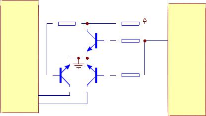
1. Open/close drive circuitis shown as inthe following figure 3.2.3.1:
|
|
TRSO |
|
R203 27K |
|
|
|
|
||||||||||||
FC+ |
|
STBY |
|
|
|
|
|
|
|
|
|
|
|
|
|
|
|
|
||
FC- |
|
V1P4 |
|
|
|
|
|
|
|
|
|
|
|
|
|
|
|
|
||
SP- |
|
|
|
|
|
|
|
|
|
|
|
|
|
|
|
|
|
|||
SP+ |
|
FMSO |
|
R202 15K |
|
|
|
|
||||||||||||
LOAD+ |
AM5888S |
|
|
|
|
|
|
|
|
|
|
|
|
|
|
|
|
|||
LOAD- |
TRCLOSE |
|
|
|
MT1389D |
|||||||||||||||
|
|
|
|
|||||||||||||||||
TK- |
|
|
|
|
|
|||||||||||||||
|
TROPEN |
|
|
|
|
|||||||||||||||
TK+ |
|
|
|
|
|
|||||||||||||||
SL+ |
|
DMSO |
|
|
R314 |
|
|
|
|
|
|
|
|
R201 |
|
|||||
SL- |
|
|
|
|
|
|
||||||||||||||
|
|
|
|
|
|
|
||||||||||||||
|
|
|
|
|
10K |
10K |
||||||||||||||
|
|
FOSO |
|
|
|
|
R204 |
|
|
|
27K |
|||||||||
Figure 3.2.3.1 Open/close drive circuitdiagram
2. Working principle: when the machine is reading discs normally, pin 6, 7, 9 10 of AM5888S are all 0V. After OPEN button is pressed, pin 6 inputs high level, pin 10 LOAD+ outputs high level, electric machine rotates to perform OPEN acts. When closing, pin 9 LOADoutputs high level to pin 9 through electric machine to formloop, electric machine rotatesreversely to perform CLOSEacts. Afterclosing to proper position, all pins are all low level. Servo drive principle is the same with the drive of D5954 scheme, so we willnot describe here.
3.2.4 Laser power control circuit
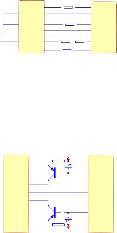
Laser power control circuitis shown as inthe following figure 3.2.4.1:
R301 4.7RLDO-AV33
|
|
|
|
|
|
|
|
|
TC302 |
|
|
|
|
|
|
|
|
|
|
|
|
|
|
|
|
|
|
|
47uF/16V |
|
|
|
|
||||||
|
|
|
|
|
|
|
|
|
LDO2 |
|
23 |
|
|
V301 |
|||||
|
|
||||||||
|
|
|
2SB1132-S 20/21 |
||||||
HA1 |
MD1 |
||||||||
20 |
|
|
|
|
|
|
|
MT1389D |
|
|
|
|
|
|
|
|
|
|
|
|
19 |
|
|
V302 |
|||||
|
|
||||||||
|
|
|
2SB1132-S |
||||||
|
|
|
|||||||
|
|
|
|
||||||
|
|
|
|
|
|
|
|
|
LDO1 |
|
|
|
|
|
|
|
|
|
TC303 |
|
|
|
|
|
|
|
|
|
|
|
|
|
|
|
|
|
|
|
47uF/16V |
|
4.7R R302 LDO-AV33 |
||||||||
|
Figure 3.2.4.1 Laser power controlcircuit diagram |
||||||||
- 18 -
2. Working principle
Pin 20/21 of MT1389 is laser power detect signal input pin, pin 21 is DVD laser power strong/weak detect signal input pin, pin 23 is VCD laser power drive control output pin, pin 22 is DVD laser power drive control output pin.
When reading VCD disc, laser power becomes weak, voltage of MDII pin decreases, voltage decrease of pin 23of MT1389 makes voltageof pin 19 ofXS301 increase to reachthe purpose of raising laser power. When laser power is too strong, voltage of MDII pin increases to lead to voltage of pin 23 of MT1389 increase to make voltage of pin 19 of XS301 decrease to reach the purpose of reducing laser power to form anauto power control circuit.
When reading DVD disc, pin 21 is detect signal input pin, pin 22 is drive control input pin, and the working principle is thesame with that whenplaying VCD disc.
3. Key point voltage(unit: V) is shownas the following table:
Location number |
Read DVD disc |
Read VCD disc |
Location number |
Read DVD disc |
Read VCD disc |
|
|
|
|
|
|
V301_E |
2.9V |
3.2V |
V302_B |
3.2V |
2.2V |
|
|
|
|
|
|
V301_B |
2.2V |
3.2V |
V302_E |
3.2V |
2.9V |
|
|
|
|
|
|
V301_C |
2.2V |
0 |
MT1389_20 |
0.2V |
0.2V |
|
|
|
|
|
|
V302_C |
0 |
2.2V |
|
|
|
|
|
|
|
|
|
3.2.5CD/DVD conversion circuit
1.CD/DVD conversion circuitis shown as inthe following figure 3.2.5.1:
|
|
|
R308 |
|
|
|
|
|
|
|
R309 AVCC |
||||
|
|
|
|
|
|
|
|
|
|
|
|
|
|
|
|
|
|
|
100K |
|
|
|
|
|
|
|
10K |
|
IOA |
||
|
|
|
|
|
|
|
|
|
|
|
|||||
|
|
|
|
|
|
|
|
|
|
|
|
|
R311 |
|
|
|
|
|
|
|
|
|
|
|
|
|
|
|
|
|
|
|
|
|
|
|
|
|
|
|
V305 |
10K |
|
|
|||
HA1 |
|
|
|
|
|
|
|
|
3904-S |
|
MT1389D |
||||
|
|
|
|
|
|
|
|
||||||||
|
|
|
|
|
|
|
|
|
|
|
|
|
|
||
|
|
|
|
|
|
|
|
|
|
|
|
|
R310 |
|
|
|
|
|
|
|
|
|
|
|
|
|
|
|
|
|
|
|
|
V303 |
|
|
|
|
V304 |
100K |
|
|
|||||
17 |
|
|
|
|
|
2SK3018-S |
|
|
|||||||
2SK3018-S |
|
|
|
|
|
|
|
|
|
|
|||||
18 |
|
|
|
|
|
|
|
|
|
|
|
|
|
|
|
Figure 3.2.5.1 CD/DVD conversion circuitdiagram
2. Working principle
After loading disc in the player, IOA port of MT1389 is defaulted high level to make V305 saturation on and form loop together with CD laser power control circuit on CD. At the same time, IOAalso goes to
- 19 -
Loader PD IC to switch, disc begins to rotate, when servo management system recognizes that the disc in player is notCD disc, IQApin outputs low levelto make V305 cutoff and make V303 on, and formloop together with DVD laser power control circuit on loader to perform disc reading acts. After disc tray door opens, IOA keeps the state before opening disc tray door. If the player cannot recognize which disc it is, IQA pinwill switch continuously untilreading disc or systemjudges that there isno disc.
Note: V303 and V304are MOS tube
3. Key point voltage(unit: V) is shownas the following table:
|
|
V305 |
|
|
V303 |
|
|
V304 |
|
|
|
State |
|
|
|
|
|
|
|
|
|
|
|
Base |
CollectorC |
Emitter E |
Grid |
Drain |
Source |
G |
D |
S |
IOA |
||
|
|||||||||||
|
electrode B |
electrode G |
electrode D |
electrode S |
|||||||
DVD disc |
0 |
3.86 |
0 |
3.81 |
0.18 |
0 |
0 |
0 |
0 |
0 |
|
|
|
|
|
|
|
|
|
|
|
|
|
VCD disc |
0.64 |
0.1 |
0 |
0 |
0 |
0 |
3.27 |
0.18 |
0 |
3.3 |
|
|
|
|
|
|
|
|
|
|
|
|
3.2.6 Main axis control circuit
1. Main axis controlcircuit is shown asin the following figure3.2.6.1:
|
C4 |
2200pF |
|
|
C5 |
|
|
|
|
|
|
0.1uF/NC |
|
|
R11 |
680k |
OPO |
R93 |
0 |
ADIN |
|
|
|
|
|
|
OP- |
|
|
|
|
|
|
OP+ |
R15 |
|
|
R16 |
|
|
R17 |
150k |
|
|
150k |
|
C16 |
680k |
|
|
|
|
|
2200pF |
|
|
R20 |
NC |
|
|
J2 |
V1P4 |
|
|
|
|
|||
SP- |
R23 |
1 |
|
1 |
|
|
SP+ |
|
|
|
2 |
|
|
LIMIT |
|
|
|
3 |
|
|
SL- |
|
|
|
4 |
|
|
|
|
|
5 |
|
|
|
SL+ |
|
|
|
6 |
|
|
DV33 |
|
|
|
6x1 W/HOUSING |
|
|
R24 10k
Figure 3.2.6.1 Main axis controlcircuit diagram
2.Function: disc is always in high speed rotation in the course of disc reading, when you need to open the door to change disc, MT1389 stops the positive direction drive signal which is given to main axis drive circuit, for the function of inertia disc is still rotating. If disc out order is performed at this time, disc will be abrasively damaged. Therefore, machine must be baking to main axis, that whether disc hasstopped rotating and whether disc is reversing, decode chip of the machine cannot recognize. So a main Axis control circuit is added to make decode chip can effective monitor that whether disc has stopped rotating.
3.Working principle: MT1389 has a comparator inside composed of operational amplifier, in which OP+ is the in-phase input end of operational amplifier, OPis reverse input end, OPO is output end,
-20 -

When playing disc normally, for electric machine is positive direction rotating, voltage of OP+ is higher than that of OP-, voltage of OPO is more than 1.4V. When disc out is needed, main axis drive signal stops, for electric machine is permanent magnetic, when in rotating, induced electromotive force produces in two ends to give to decode chip through R320, R319 sampling to make OPO output less than 1.4V voltage and transmit to input pin of MT1389 ADIN through R331. When ADIN is high level, main axis drive output end has not any drive signal output, when ADIN is low level, MT1389 outputs a reversing drive signal to main axis drive circuit to make main axis electric machine speed down. Thus circular working goes on until main axis stops rotating. PDVD is manual disc out means, so after disc out, disc is still rotating, but will stop very son.
4. Key point voltage (unit: V) is shown as the following table:
Key point |
Position |
Normal working voltage (V) |
Volateg change when disc out (V) |
|||
|
|
|
|
|
|
|
SP+ |
Pin 11 of AM5888S, pin 5 of |
3.79 |
3.79 |
0.70 |
1.80 |
|
XS307 |
||||||
|
|
|
|
|
||
SP- |
Pin 12 of AM5888S, pin 6 of |
1.38 |
1.38 |
3.40 |
1.80 |
|
XS307 |
||||||
|
|
|
|
|
||
OP+ |
Pin 36 of MT1389 |
1.38 |
1.38 |
3.10 |
1.80 |
|
|
|
|
|
|
|
|
OP- |
Pin 35 of MT1389 |
1.53 |
1.53 |
3.08 |
1.98 |
|
|
|
|
|
|
|
|
OPO |
Pin 34 of MT1389 |
2.44 |
2.44 |
0.40 |
2.50 |
|
|
|
|
|
|
|
|
ADIN |
Pin 47 of MT1389 |
2.44 |
2.41 |
0.41 |
2.44 |
|
|
|
|
|
|
|
|
DMSO |
Pin 4 of AM5888S |
1.42 |
|
1.42 |
|
|
|
|
|
|
|
|
|
VIP4 |
Pin 30 of MT1389 |
1.41 |
|
1.41 |
|
|
|
|
|
|
|
|
|
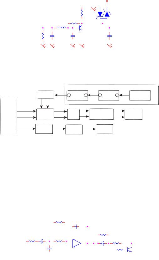
3.2.7 Decode circuit
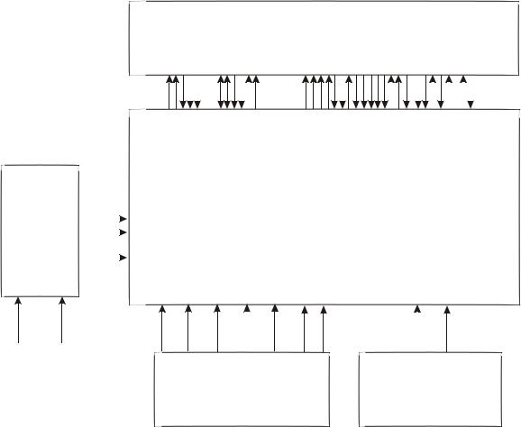
1.Decode circuit block diagram is shown as in the following figure 3.2.7.1:
2.Working principle: this decode circuit is mainly composed of MT1389, SDRAM and FLASH. Working condition of decode circuit has:
(1) Reset: refer to reset circuit working principle for details.
(2) Clock: this system adopts 27M external clock input, and produces clock signal required by system inside through internal frequency doubling circuit.
(3) Power: decode chip adopts twp groups power supply of 3.3V and 1.8V, in which 1.8V mainly s u p p l y p o w e r f o r i n t e r n a l l o g i c c o n t r o l c i r c u i t a n d w e c a l l i t c o r e v o l t a g e .
After power on, reset circuit performs reset to MT1389 built-in CPU (8032) and FLASH, decode chip outputs reset signal at the same time and performs reset to other circuit. After system reset, it firstly Sends out read signal to FLASH to read out in formation saved in FLASH, the machine displays poweron picture, servo system begins to work to check whether machine closes door to proper position and
- 21 -
PWR |
SDCLK |
PRD |
SDCKE |
PCE
FLASH
A0~A20
MT 1389
DCS
DRAS SDRAM
SWE
DQM0
AD0~AD7 |
|
|
|
DQM1 |
|
|
|
|
DQ0~DQ15 |
||
URST |
|
|
|
||
|
|
|
MA0~MA11 |
||
|
|
|
|
||
|
SDA |
|
V18 |
|
|
|
SCL |
|
|
||
|
|
|
|
||
Reset |
EEPROM |
Clock |
1.8V |
3.3V |
|
voltage |
voltage |
||||
24C02 |
27M |
||||
circuit |
regulating |
regulating |
Figure 3.2.7.1 Decode circuit blockdiagram
Whether detect switch has been closed, if not, the door close action is performed. After detect switch of door is closed, the machine begins to perform preparations of disc reading and performs panel display at the same timeof working.
Playback process: laser head picks up disc signal from disc, after servo system processing, then send to decode circuit for decoding, signal after being decoded is saved in SDRAM for the moment. When machine needs to replay signal, decode circuit calls information inside SDRAM to perform D/A conversion and then output.
User information storage: informationcontent set by useris saved inside EEPROM,if user does not refresh or reset thisinformation, it will savedin IC permanently.
Audio, video output circuit: at present, MT1389 all integrates video D/A converter, MT1389D inside integrates audio D/A converter, manufactures select according to their own needs. Please refer to circuit principle diagram andaudio circuit explanation fordetails.
3.2.8 Reset circuit
1. Reset circuit isshown as in thefollowing figure 3.2.8.1:
RESET Circuit
DV33
+CE9
10uF/10V
R7 100R
R3
10K
URST#
3
1Q18
2N3904
SOT23
2
D3 1N4148 
R6
10K
Figure 3.2.8.1 Reset circuit diagram
- 22 -
2.Working principle: after power on, voltage of DV33 increases to 3.3V, main chip power supply is normal. Now, voltage of CE9 to DV33 cannot change suddenly to make base electrode of Q18 has current flow in, Q18 is saturation on, URST is low level. DV33 charges CE9 in two paths through emitter junction of R6 and Q18 make negative pole voltage of CE9 decrease slowly. When this voltage decreases below 0.7V, V310 cuts off, URST changes into high level, the process for URST from low to high is called effective reset signal of low level by us. After power off, voltage of DV33 decreases, CE9 decreases together with DV33 voltage, D3 performs suge discharge and clampingto CE9.
3.Key point voltage(unit: V)
Q18_B is low level |
when in normal condition, at the moment of power on, it decreased to 0V from |
3.3Vgradually. |
|
Q18_C is high level |
when in normal condition,at the moment ofpower on, it increasesto 3.3V from |
0V. |
|
3.2.9Video circuit
1.Video signalflow chart diagram isshown as in thefollowing figure 3.2.9.1:
MT1389
SY
|
|
|
|
|
|
S-Video |
|
|
|
|
SC |
|
Jk202A |
|
|
|
|
|
|
|
179 |
Y4 |
L21 |
|
L240 |
|
11 |
181 |
Y5 |
L23 |
|
L239 |
|
7 |
|
|
|
|
|
|
SCART |
182 |
Y6 |
L22 |
R/V/SY |
L241 |
|
Terminal |
|
|
15 |
||||
|
|
|
|
|||
175 |
Y3 |
L25 |
CUBS |
R284 |
CVBS# |
19 |
|
|
|
||||
|
|
|
|
|
|
Jk202B |
|
|
|
|
|
|
CVBS -Video |
|
|
Figure 3.2.9.1 Video signalflow chart |
|
|||
2. Working principle: MT1389D has built-in video D/A conversion circuit, video output has R/B/G Y/Pb/Pr Y/Cb/Cr CVBS Y/C output mode, in which R/B/G Y/Pb/Pr Y/Cb/Cr Y/C cannot output at the same time and need the switch through software. CVBS is a separate output mode, 4-path video signal outputted by MT1389, throughvideo filtering clamping, outputto Terminal.
Shown as in the figure 3.2.9.2, capacitor C61,C50 and inductor L25 compose a low-pass filter to filter high frequency disturbance signal except useful signal; dual diode Q10 composes a limiter
- 23 -
Circuit, known from featuresof diode that themax amplitude of compositevideo signal CVBS cannotbe over 5.7, and the mix cannot be less than -0.7, thus the high voltage signal from TV set can be avoided burning down the player.
|
|
|
5V |
2 |
1 |
|
|
|
|
Q10 |
|
|
|
|
R86 |
|
|
|
|
|
|
BAV99 |
|
|
|
|
NC |
|
|
|
|
|
|
|
|
|
|
|
L7 |
|
|
|
|
|
0R |
|
|
|
L25 |
1.8uH |
|
2 |
3 |
CVBS |
|
Q5 |
CVBSO |
||
|
|
1 |
|||
|
|
|
|
NC |
|
R90 |
C61 |
|
C50 |
3 |
C82 |
75,1% |
100P |
100P |
|
100P |
|
|
|
||||
Figure 3.2.9.2 Video outputcircuit
3.2.10 Audio circuit
1. Audiosignal flow chart blockdiagram is shown inthe figure 3.2.10.1:
MIC board
R2132 |
OKA |
U5A |
6 |
1 U5B |
3 |
MIC holder |
R2156 |
7 |
MT1389
189 |
AL |
6 |
7 |
CH-L |
L235 |
13 |
Audio |
L# |
|
|
|
|
|
|
|||||
187 |
AR |
U13 |
1 |
CH-R |
L236 |
14 |
Jk201 terminal |
R# |
SCART |
|
2 |
|
|
|
|
|
|||
170 |
SAPDIF |
R72 |
|
|
C81 |
|
Coaxial |
|
|
|
|
|
|
|
|
Figure 3.2.10.1 Audiosignal flow chart block diagram
2. Working principle: MT1389D has built-in audio DAC conversion circuit, which stimulates signals and outputs from decode chip directly, through audio amplifying and filtering circuit, and outputs audio signals directly. Shown in the figure 3.2.10.2, the right channel analog signals outputted by decode chip are coupled by C75 and then the highfrequency component in audiosignals is filtered bythe low pass filter composed of R97 C77, for signals are damped through filtering circuit, the audio signals after being filtered require the amplifying output by the amplifying circuit composed of U13A, R122 is feedback resistor,this circuit is aactive filter on thewhole.
LMAIN1
|
|
R116 |
|
|
31k |
|
|
R118 |
R97 |
C75 10uF/6.3v |
5.1k |
|
+ |
|
10k |
|
C77 |
|
|
|
|
|
1000pF |
C74 100pF
-12V
|
4 |
U13A |
|||
2 |
|
|
|||
- |
|
1 |
|||
3 |
|
||||
+ |
|
|
|
||
|
NJM4558 OPA |
||||
|
8 |
||||
|
|
|
|
||
|
|
|
+12V |
|
|
L24
NC
R119
100R
+
R100 1K 10uF/6.3v A_MUTE 1 C70 
LCH
3
Q14
2N3904
SOT23 2
Figure 3.2.10.2 Amplifyingcircuit diagram
- 24 -
3. External Karaoke signalinput and output
After being amplified, MIC signals input to pin 2, 6 of U13 separately for amplifying output.
3.2.11 Mute circuit
1. Mute circuit isshown as in thefigure 3.2.11.1:
+12V
VCC
R91
R87
470R 15K
D5 |
CE29 |
+ |
4.7V 220UF/10V
R120
10K
1
V33 |
|
|
|
|
|
2 |
|
MUTE_DAC |
1 |
Q17 |
|
R134 |
10K |
3906 |
|
3 |
|||
|
|
|
|
2 |
|
|
1 |
Q15 |
|
|
3906 |
||
R89 |
10K |
||
3 |
|||
|
|
||
2 |
|
|
|
Q21 |
|
|
|
3906 |
|
|
|
3 |
|
|
A_MUTE
R135 750k
-12V -12V
-12V
Figure 3.2.11.1Mute circuit
2. Working principleof quieting circuit
When the player is working normally, shown in the figure 3.2.11.1, MT1389E outputs analog audio signal, and a low level signal to MUTE-DAC at the same time to make Q17on, B electrode of Q17 is about 2.7V, collector electrode ofQ17 is about 3.3V, so Q15 is also on, voltage ofB electrode is about 0.7V, voltage of Q21 E electrode is near to zero, Q21 cuts off, MUTE 1 is negative voltage, which is added to base electrode of mute tube of audio output end to make mute tube cut off, and audio signal outputs after being amplified by 4558. When pressing MUTE button on remote controller, MT1389 has no audio signal that outputs to operational amplifier, so audio output end of the player has no audio signal output, but because electronic elements in circuit will produce some noise when working that transmits to output endof the player, in order tofilter there noise, decodechip outputs a highlevel signal to MUTE-DAC to make Q21 cut off, so Q15 cuts off, +5V power is transmitted to base electrode of switch pipe Q15 through EC electrode of Q21 , mute circuit is inmute state.
When player is not playing disc or stops playing, MT1389D outputs a high level signal to MUTEDAC to make audiocircuit enter mute state.
After microphone is inserted into the machine, DET pin outputs low level, Q21E electrode is low level, now no matter the former circuit outputs mute circuit, rear mute circuit does not work, and sound outputs normally.
- 25 -
 Loading...