


SW-8

PHOENIX
SW - 8
SW - 10
SW - 12
Service Manual
SW-8 Principle ans Servicing
3PHOENIX
R
L
SW
GND
R
L
SW
GND
G ND
SW1
+12 V
-
1 2V
S W1
G ND
-1 2V
+12 V
~29
~14
GND
~14
~29
~29
~14
GND
~14
~29
LPF FILTER
LPF FILTER
R
R
L
L
7PHOENIX SUB
PHASE CONTROL
PHASE CONTROL
INPUT BOARD
Frequency adjust
Volume adjust
POWER SUPPLY
SW POWER
AMPLIFIER
R SPEAKER
L SPEAKER
SW SPEAKER
AMPLIFIER
OUTPUT
CPHOENIX
R&L CONECT BOARD
INPUT BOARD
TRANSFORMER
AMPLIFIER BOARD
4PHOENIX SUB
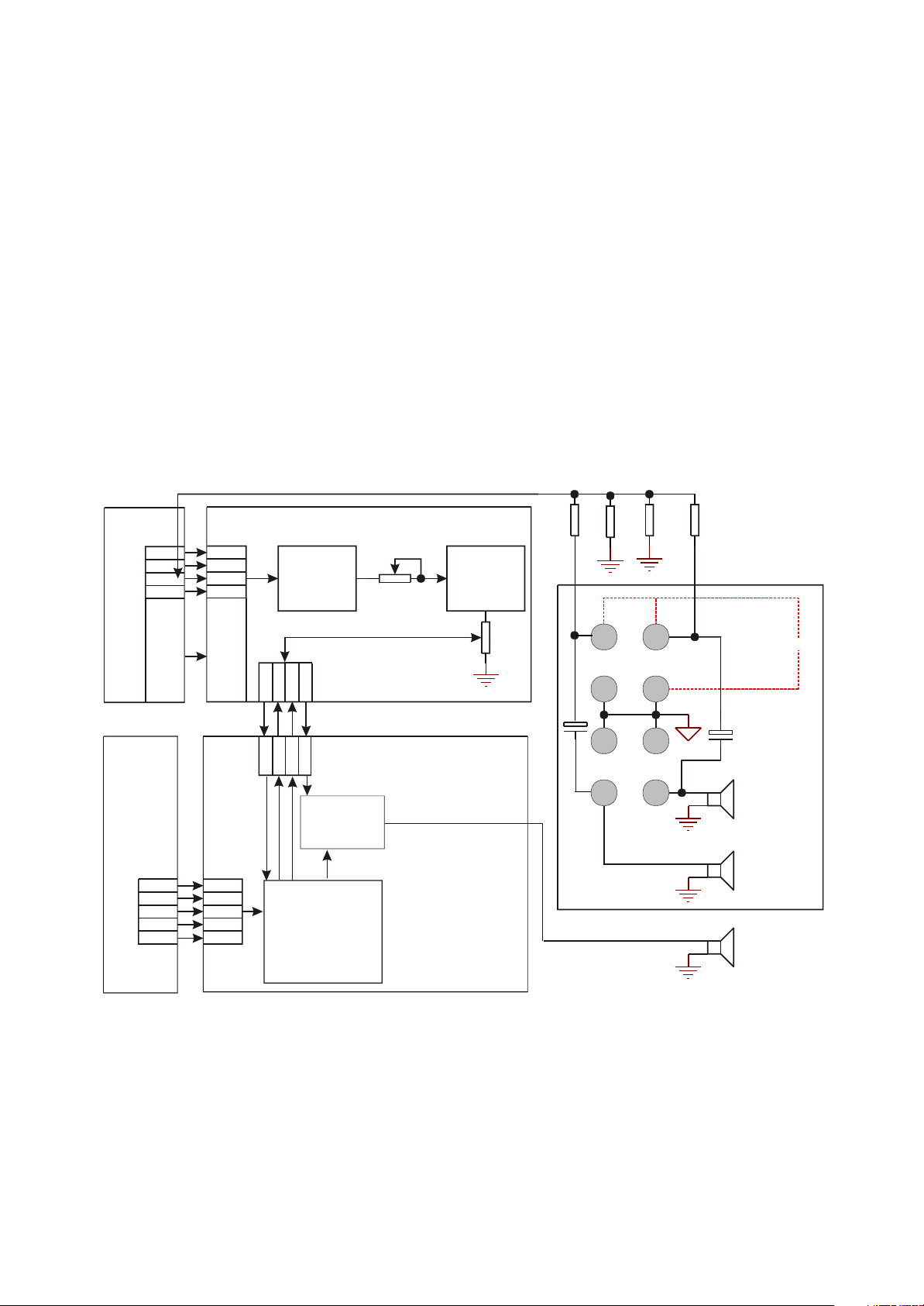
1. Block diagram of the player
Block diagram of the player is shown in the figure 1.1:
Figure 1.1 Block diagram of the player
2. SW-8 working principle
SW-8 is composed of a bass loudspeaker and left/right channel loudspeaker; signals input from
input board; left and right channel signals (L, R) directly output to left and right loudspeaker; bass
signals (SW) perform pre-amplifying processing through 4558 and fulfil phase and volume control, and
- 1 -

Then input to power amplifying circuit of power amplifier board. SW signals perform differential
amplifying through the differential circuit composed by V301 V304, and then perform composite power
amplifying through rear stage triode and output to bass loudspeaker.
To protect bass loudspeaker, this player has over-voltage and over-current protection circuit.
Protection method is that disconnect loudspeaker output through disconnecting relay Y301 when
protection starts up.
A over-voltage sampling circuit is connected on SW output end which is composed of R353 and
R337. When output central point of a channel is over +4.3V or lower than -4.3V DC voltage, V318 or
V317 is on to make their C electrode voltage decrease, V319 is also on and finally relay disconnects and
loudspeaker output is disconnected. Over-current protection principle is the same with that of over-
voltage, a over-current sampling triode V313 is connected on output load resistor and load resistance is
R323, R324. When over-current trouble appears, voltage drop that produces on R323, R324 will
increase quickly, once it exceeds B electrode voltage of V303, V313 is on and V319 is also on, finally
relay is connected and loudspeaker output is disconnected.
3 Function introduction to 4558
(1) Description
The RC4558 and RM4558 devices are dual general-purpose operational amplifiers with each half
electrically similar to the A741 except that offset null capability is not provided.
The high common-mode input voltage range and the absence of latch-up make these amplifiers
ideal for voltage-follower applications. The devices are short-circuit protected and the internal frequency
compensation ensures stability without external components.
The RC4558 is characterized for operation from 0?C to 70?C, and the RM4558 is characterized for
operation over the full military temperature range of 55 C to 125 C.
(2) FEATURES
Continuous-Short-Circuit Protection
Wide Common-Mode and Differential
Voltage Ranges. No Latch-Up
No Frequency Compensation Required
Low Power Consumption
Unity-Gain Bandwidth . . . 3 MHz Typ
Gain and Phase Match Between Amplifiers
Low Noise . . . 8 nV?Hz Typ at 1 kHz
Designed To Be Interchangeable With
Raytheon RC4558 and RM4558 Devices
- 2 -

PIN No Symbol I/O Description
1 1OUT O Output 1
2 1IN– I Inverting Input Pin 1
3 1IN+ I Non-Inverting Input Pin 1
PIN No. Symbol I/O Description
PIN No. Symbol I/O Description
4 V CC– I Negative Pow er Supply
5 2IN+ I Non-Inverting Input Pin 2
6 2IN– I Inverting Input Pin 2
7 2OUT O Output 2
8 V CC+ I Positive Pow er Supply
(3) PIN CONFIGURATION
- 3 -
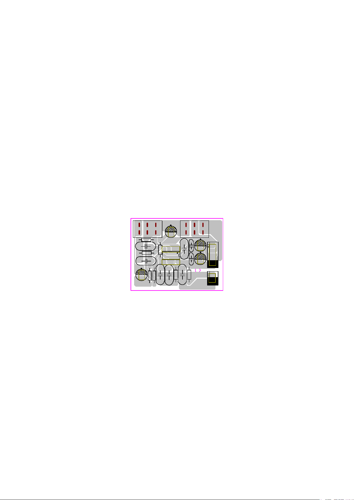
3PHOENIX-0
C109
C106
C111
R102
C107
R101
R103
R104
C105 C104
R105
C103
R107
C101
R106 RP101
N101
C108
C102
C112
RP102
OUT
051110
XS4
+12 -12G
C110
IN
XP3
4. PCB Board
- 4 -
(1) signal Board
 Loading...