


DK1110SI

service manual
DK1110SI

Catalog
1.1 Safety precautions
1.1.1 Power supply
1.1.2 Precautions for antistatic
1.1.3 Precautions for laser head
1.1.4 About placement position
1.2 Maintenance method
1.2.1 Visualized method
1.2.2 Electric resistance method
1.2.3 Voltage method
1.2.4 Current method
1.2.5 Cutting method
1.2.6 Element substitution method
1.2.7 Comparison method
1.3 Required device for maintenance
Chapter One About Maintenance
Chapter Two Functions and Operation Instructions
2.1 Features
2.2 Controls and functions
2.2.1 Front panel controls
2.2.2 Rear panel connections
2.2.3 VFD display general view
2.2.4 Remote control general view
2.3 Setlist
2.4 FUNCTION SETTINGS
2.4.1 Function selection and change
2.4.2 Language settings
2.4.3 Image settings menu
2.4.4 Sound settings menu
2.4.5 Playback settings
1
1
1
1
1
2
2
2
2
2
2
2
3
3
3
4
4
5
5
5
6
6
7
7
7
7
8
8
9

2.4.6 Karaoke settings menu
2.4.7 Preference settings
2.4.8 Family filter settings
2.4.9 Initial settings menu
2.4.10 Reset settings to default
2.4.11 Exit settings menu
2.4.12 Channel delay set-up
2.5 Technical characteristics
Chapter Three Principle and Servicing
Section One Principle of the Player
3.1.3 PCB board composition diagram of the player
Section Two Unit Circuit Principle
3.2.1 Loader signal explanation
3.2.2 Servo circuit
3.2.3 Mute circuit
3.2.7 Disc identification circuit
3.2.8 Panel control components
3.2.11 Audio power amplifying circuit block diagram
3.2.12 Power circuit
Section Three Servicing Cases
3.3.1 Servicing cases
Section Four Signal waveform diagram
3.1.1 Features of the player
3.1.2 Block diagram of the player
3.1.4 Introduction to IC used in this player
3.2.4 Open/close door circuit
3.2.5 Reset circuit
3.2.6 Main axis braking control circuit
3.2.9 Video circuit
3.2.10 Input/output circuit
3.3.2 Troubleshooting flow chart
Section Five Function Introduction to IC
3.5.1 function introduction to MT1389E
3.5.2 function introduction to AT24C02
10
10
10
10
11
11
11
12
14
14
14
14
16
17
18
18
19
22
23
24
25
26
27
28
29
31
33
35
38
45
47
47
61

3.5.3 function introduction to 74HCU04
3.5.4 function introduction to Lm1117
3.5.5 Function introduction to 29LV160BE
3.5.6 Function introduction to HY57V641620HGT-7
3.5.7 Function introduction to Cd4094
3.5.8 Function introduction to D5954
3.5.9 function introduction to 4558
3.5.10 function introduction to M62429
3.5.11 function introduction to TDA8947J
3.5.12 function introduction to 4580
3.5.13 function introduction to 5340
3.5.14 function introduction to Pt2314
3.5.15 function introduction to Pt6961
3.5.16 function introduction to KA5L0380R & KA1M0880BTU
3.5.17 Function introduction to HS817
3.5.18 Function introduction to TL431A
Chapter Cinque PCB board & Circuit diagram
Section One PCB board
Section Two circuit diagram
Chapter six BOM List
Chapter Four Disassembly and Assembly Process
62
63
63
64
65
66
67
68
69
70
71
72
73
75
76
76
78
79
79
86
91

Chapter One About Maintenance
1.1 Safety precautions
1.1.1 Power supply
When maintenance personnel are repairing DVD players, he should pay special attention to the
power board with 220V AC and 330V DC which will cause hurt and damage to persons!
1.1.2 Precautions for antistatic
Movement and friction will both bring static electricity which causes serious damages to integrated
IC. Though static charge is little, when a limited quantity of electric charge is added to large-
scaleintegrated IC, as the capacitance is very small in the meantime, now the integrated IC is very much
easy to be struck through by static electricity or the performance will decrease. Thus static electricity
prevention is of extraordinary importance. The following are several measures to prevent static
electricity:
1. Use a piece of electric conduction metal with the length of about 2 metres to insert into the earth,
and Fetch the lead wire from the top of the surplus metal and connect to the required static electricity
device. The length and depth of the metal embedded under the earth should be determined according to
the wettability of the local soil. For humid places, it may be shorter, and longer and deeper for dry places.
If possible, it can be distributed and layed in terms of “#” shape.
2. On operating table-board, the antistatic table cushion should be covered and grounded.
3. All devices and equipments should be placed on the antistatic table cushion and grounded.
4. Maintenance personnel should wear antistatic wrist ring which should be grounded.
5. Places around the operating position should also be covered with electric conduction cushion or
Painted with antistatic paint.
1.1.3 Precautions for laser head
1. Do not stare at laser head directly, for laser emission will occur when laser head is working, which
will Hurt your eyes!
2. Do not use wiping water or alcohol to clean laser head, and you may use cotton swab.
- 1 -

1.1.4 About placement position
1. Never place DVD player in positions with high temperature and humidity.
2. Avoid placing near high magnetic fields, such as loudspeaker or magnet.
3. Positions for placement should be stable and secure.
1.2 Maintenance method
1.2.1 Visualized method
Directly view whether abnormalities of collision, lack of element, joint welding, shedding welding,
rosin joint, copper foil turning up, lead wire disconnection and elements burning up among pins of
elements appear. Check power supply of the machine and then use hands to touch the casing of part of
elements and check whether they are hot to judge the trouble spot. You should pay more attention when
using this method to check in high voltage parts.
1.2.2 Electric resistance method
Set the multimeter in resistance position and test whether the numerical value of resistance of each
point in the circuit has difference from the normal value to judge the trouble spot. But in the circuit the
tested numerical value of resistance is not accurate, and the tested numerical value of integrated IC's
pins can only be used for reference, so the elements should be broken down for test.
1.2.3 Voltage method
Voltage method is relatively convenient, quick and accurate. Set the multimeter in voltage position
and test power supply voltage of the player and voltage of a certain point to judge the trouble spot
according to the tested voltage variation.
1.2.4 Current method
Set the multimeter in current position and test current of the player of a certain point to judge the
trouble spot. But when testing in current method, the multimeter should be series connected in the
circuit, which makes this method too trivial and troublesome, so it is less frequently used in reality.
1.2.5 Cutting method
Cutting method should be combined with electric resistance method and voltage method to use.
This method is mainly used in phenomena of short circuit and current leakage of the circuit. When
cutting the input terminal voltage of a certain level, if voltage of the player rises again, it means that the
trouble lies in this level.
- 2 -

1.2.6 Element substitution method
When some elements cannot be judged good or bad, substitution method may de adopted directly.
1.2.7 Comparison method
A same good PC board is usually used to test the correct voltage and waveform. Compared these
data with those tested through fault PC board, the cause of troubles may be found.
Through the above maintenance method, theoretical knowledge and maintenance experience, all
difficulties and troubles will be readily solved.
1.3 Required device for maintenance
Digital oscillograph ( 100MHE)
TV set
SMD rework station
Multimeter
Soldering iron
Pointed-month pincers
Cutting nippers
Forceps
Electric screw driver
Terminals connecting cord
Headphone
Microphone
- 3 -

Chapter Two
Functions and Operation Instructions
2.1 Features
Compatible Disc Types:
#Digital video playback DVD-Video, Super VCD, VCD compatibility.
#MPEG-4 standard support: compatibility with DivX3.11, DivX5, DivX pro, XviD compressed video filies.
#Digital audio playback: CD-DA and HDCD compatibility.
#Fully compatible with compressed audio files such as Mp3 and WMA
#Playback of DVD, VCD, CD+G karaoke discs.
#Digital graphic albums playback: Kodak picture CD, JPEG compatibility.
Audio:
#192KHz/24 bit Audio Digital/Analog converter.
#Coaxial and optical outputs for Dolby Digital/DTS/LPCM digital audio.
#Mixed audio output for amplifier of TV connection
#Stereo signal input for external signal connection.
#Digital multi-channel decoders, providing Dolby Digital/DTS audio stream playing .
#Built-in Dolby Pro Logic ll decoder makes available to convert stereo signal into multi-channel.
#Dual-channel MIC inputs for karaoke function
#Headphones output
Video:
#108MHz/12 bit Video Digital/Analog converter
#Progressive Scan Output(Y Pb Pr) producing flicker-free and stable images
#Composite, component(Y Cb Cr), S-Video and RGB/SCART outputs for various types of connections
#NTSC/PAL transcoder
#Multiple dubbings, angles, subtitles support.
#Sharpness, gamma, brightness, contrast, hue , saturation adjustment.
Others:
#Compatible disc types: CD-R/CD-RW, DVD+R/DVD+RW
#Built-in digital FM/AM tuner with 20 radio stations memory
#KARAOKE+ system expanding karaoke function
#Russia, CIS and Baltic States adaptation interface and filenames, ID3-tags and CD-Text support
simplifies device operation.
#”Memory” function enables to save the last point after stop playback.
#:Q-Play” function provides direct playback and allows to skip commercial that is not possible to rewind.
#”Virtual keyboard” function provides more convenient DVD playback control.
#”Browser” function provides easy access to playback control.
#Automatic screensaver function
#Parental control function to protect children from watching inappropriate discs.
- 4 -
2.2 Controls and functions
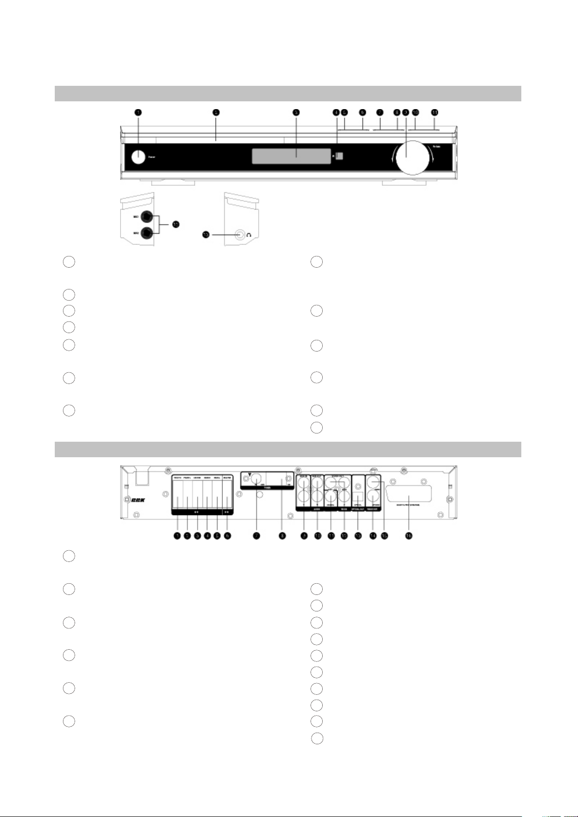
2.2.1 Front panel controls
1
STANDBY/POWER button
Press to switch the device on/into standby.
Disc tray
VFD display window
Infrared sensor
OPEN/CLOSE button
Press to open/close the disc tray.
PLAY/PAUSE button
Press to playback/pause
STOP button
Press to stop the playback
2
3
4
5
6
7
8
SOURCE button
Press to switch between DVD-receiver/Audio
Input/Radio
VOLUME adjuster
Press to adjust volume
REW button
Press to fast reverse
Forward button
Press to fast forward/radio station tuning
Dual-channel MIC Inputs
Headphones outputs
9
10
11
12
13
2.2.2 Rear panel connections
1
Right front speaker input(output from the built-
in amplifier)
Left front speaker input (output from the built-in
amplifier)
Center speaker input(output fro the built-in
amplifier)
Right Surround speaker input(output from the
built-in amplifier)
Left Surround speaker input(output from the
built-in amplifier)
Subwoofer input(output from the build-in
amplifier)
2
3
4
5
6
7
FM Antenna input
AM Antenna input
Audio input
Stereo audio output
Coaxial digital audio output
Component video output Y Cb(pb)Cr(pr)
Optical digital audio output
S-Video output
Composite video output
SCART
8
9
10
11
12
13
14
15
16
- 5 -
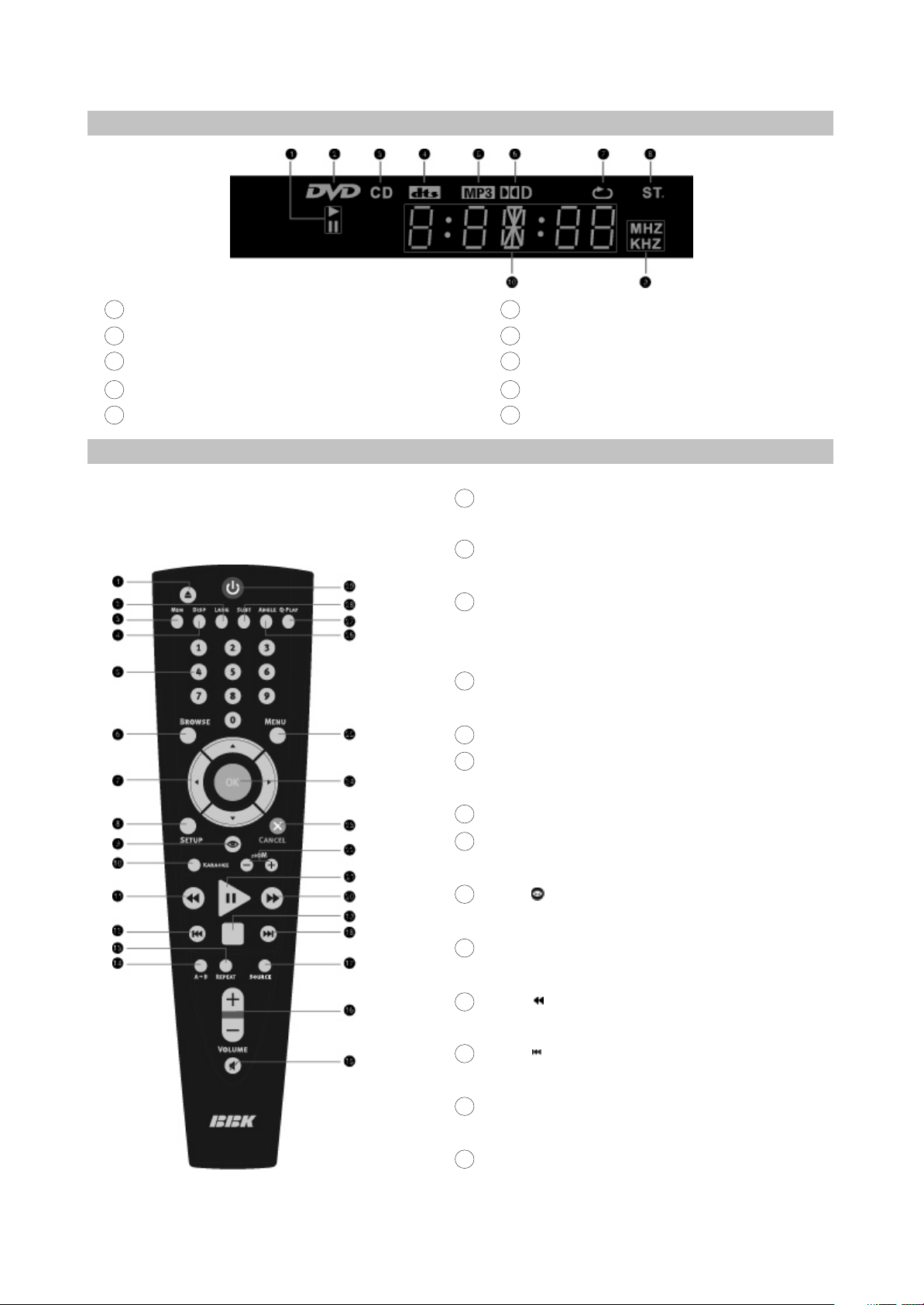
2.2.3 VFD display general view
Playback/pause
DVD-disc
CD-disc
DTS
Mp3
1
2
3
4
5
Dolby Digital
Repeat
Stereo
Friquency
Universal letter-digital indicator
6
7
8
9
10
2.2.4 Remote control general view
EJECT button
Press to open/close the disc tray.
LANG button
Press to change language.
NEM button
Press to memorize the point where playback was
stopped/playback fro the previously memorized point.
DISP button
Press to display the disc information
Numeric buttons
BROWSE button
Press to turn on/off the browser function.
CURSOR buttons
SETUP button
Press to switch to setup mode.
Button
Press to start rewind/rewind scanning.
KARAOKE button
Press to set the karaoke functions.
Button
Press to stip backward
Button
Press to skip backward
REPEAT button
Press to repeat playback
A-B button
Press to repeat the selected protion.
1
2
3
4
5
6
7
8
9
10
11
12
13
14
- 6 -
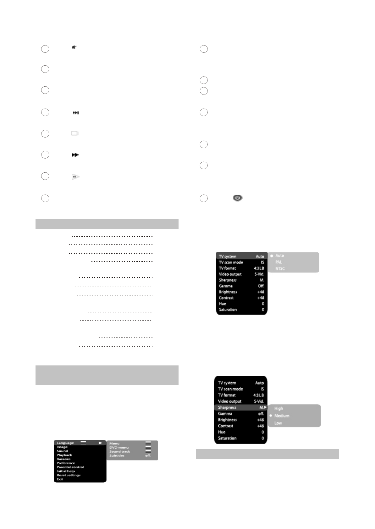
Button
Press to turn on/off the sound.
VOLUME+/- button
Press to adjust the volume.
SOURCE button
Press to change the DVD/RADIO/AUX mode.
Button
Press to skip forward
Button
Press to stop the playback.
Button
Press to start forward/ffoward scanning
Button
Press to normal playback/pause
ZOOM+/- button
Press to zoom in/out
15
16
17
18
19
20
21
CANCEL button
Press to go one level back/cancel current
operation
Ok button
MENU button
DVD disc menu/PCB function
ANGEL button
Press to change the camera angel/change the
Mp3 and JPEG files playback mode
Q-PLAY button
Press to turn the Q-Play mode on.
SUBT button
Press to change the subtitles language/change
the playback mode of Mp3 and JPEG files.
Button
Press to switch the device on/into standby.
23
22
24
25
26
27
28
29
2.3 Setlist
DVD receiver
Speakers
Subwoofer
Audio/Video Cord
2xRCA-Mini-Jack audio cord
Speaker cord
FM Antenna
AM Antenna
Remote control
AAA size battery
Warranty card
User manual
DM-998 microphone
Karaoke disc
1PCS
5PCS
2PCS
1PCS
1PCS
6PCS
1PCS
1PCS
1PCS
2PCS
1PCS
1PCS
1PCS
1PCS
2.4 FUNCTION SETTINGS
2.4.1 Function selection and
change
Press the SETUP key to show the setup
menu. You will see the following image on the
screen, as shown on the figure:
Select the desired menu item using the UP/
DOWN buttons button; Press the OK key for
confirmation.
1.For example, if you wish to change the image
settings, you have to select the image item
and press the OK or RIGHT key.
2.Using the UP/DOWN buttons, select the
desired item and press OK or RIGHT button.
For example, select the Sharpness item.
Settings will appear on the screen. Then
select the desired sharpness level and press
OK for confirmation.
2.4.2 Language settings
1.Menu: inteerface language set-up
#Options:Rusian, English, Ukrainian
#Default option: Englis
- 7 -

2.DVD-menu: selection of disc menu language
3.Sound: selection of translation language
#Disc menu/translation language options:
Russian, English, Estonian, Lithuanian,
Kazakh, Romanian, Belarusian, Ukrainian,
Chinese.
#Default menu/translation language option:
English.
#Selection of other languages: select the
OTHERS item using the wheel and press OK.
Enter the language code using the numeric
buttons and press OK.
#If the language you selected is not recorded on
the DVD disc, another available language will
be used.
4.Subtitles: selection of subtitles language
#Options: Off, Russian, English, Estonian,
Lithuanian, Kazakh, Romanian, Belarusian,
Ukrainian, and Chinese.
#Default option: Off.
#Selection of other languages: select the
OTHERS item using the wheel and press OK.
Enter the language code using numeric
buttons and press OK.
#If the language you selected is not recorded on
the DVD disc, another available language will
be displayed.
2.4.3 Image settings menu
1.TV system: TV system selection
#Options: Auto, PAL, NTSC.
#Default option: PAL
2.TV scan mode: scan mode selection
#Options: progressive, interlaced.
#Default option: interlaced
#Progressive scan is transferred only via a
component video output.
#Before switching to progressive scan, make
sure that your TV set supports this operation
mode.
3.TV Format: image ratio settings
#Options: 4:3 pan&scan, 4:3 letterbox and 16:9
TV.
#Default option: 4:3 letterbox.
#Some discs are recorded with support of only
one ratio. The selected ratio must comply with
the TV screen.
4.Video output: selection of video signal
#Options: S-Video, Comp, RGB.
#Default option: Comp.
5.Sharpness: image sharpness adjustment
#Options: High, Medium, Low
#Default option: Medium.
6.Gamma: adjustment of image color
temperature.
#Options: High, Medium, Low, Off.
7.Brighteness: adjustment of image brightness
8.Contrast: adjustment of image contrast
9.Hues: adjustment of image hues
10.Satruation: adjustment of image saturation
Adjustment of image brightness contrast,
hues and saturation:
#Select the desired item of the image adjustment
section using the UP/DOWN buttons. Press
OK or RIGHT key to start adjusting the
relevant option.
#Upon completion press the LEFT button of the
UP/DOWN buttons to return to image setup
menu.
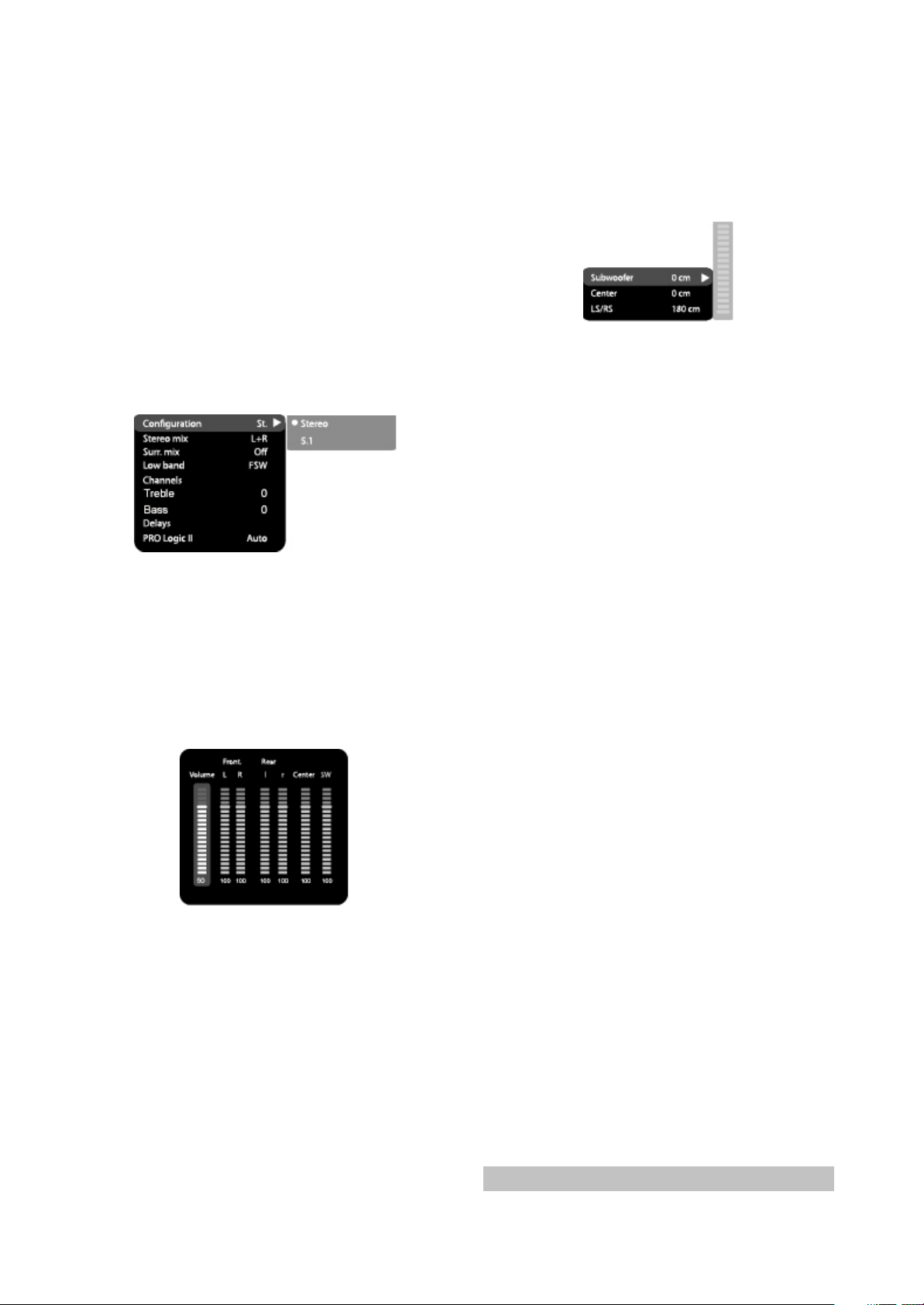
2.4.4 Sound settings menu
1.Mixer
a)Cofiguration: setting of the mode for
conversion of the 5-channel signal to stereo
signal
#Options: Stereo, 5.1.
#Default option: 5.1.
#5.1 mode must be supported by the disc.
Number of music accompaniment channels
depends on the specific disc.
#Adjustment of the central speaker and surround
speakers is available only if the Configuration
option is set to 5.1 position.
b)Stereo mix: playback set-up while playing the
disc with two independent audio channels.
#Options: L+RR, L, R.
- 8 -
#Default options: L+R.
c)Surr.mix: set-up of surround options while
playing the stereo disc.
#Options: Off, Sum. L+R, Virt. Surr.
#Default options: Sum. L+R,
d)Low band: distribution of low frequencies
through channels.
#Options: Front F, Center C, Surround Sr,
Subwoofer SW.
#Default options: Front F, Subwoofer SW.
#If you want the low-frequency component of the
sound signal enter only the subwoofer channel,
select and confirm the parameter Subwoofer
SW.
e)Channel settings: separate adjusting of
volume by channels.
#Select the channel you want to adjust using the
cursor buttons.
#Adjust the sound volume of each channel using
he cursor buttons.
#Press the OK key to return to sound settings
menu.
f)Delay of the channel: set-up of signal delay in
speaker channels(central, rear and subwoofer).
#Using the button of the cursor buttons, select
the channel, for which you want to set up the
delay, and press OK for confirmation.
#Using the cursor buttons set up the desired
distance from the listener to each
speaker(detailed description of this operation
see on page 32).
#Press the LEFT button to return to speaker
configuration menu.
g)PRO Logic ll: function of stereo sound
conversion to 5-channel sound.
#Options: On, Off, Auto.
#Default option: Off.
#In Auto position, the DVD receiver determines
itself, when to use the PRO Logic ll decoder.
Some discs do not support this function.
2.Digital audio output
a)SPDIF format: set-up of digital audio output
options.
#Options: RAW, PCM.
#Default options: RAW.
#When you select the RAW option, the not
decoded signal is transferred to the DVD
receiver’s digital outputs, the decoded signal
is transferred to analog outputs. Decoding is
performed by the built-in decoder of the DVD
receiver. This feature is meant to ensure that
signal decoding at digital outputs is performed
by an external device(e.g.an amplifier).
#If you select the PCM option, a PCM coded
signal will be transferred to the DVD receiver’s
digital outputs.
b)LPCM: set-up of digital audio output options to
comply with different amplifiers and receivers.
#Options: 48 kHz 16 bit, 96kHz 24 bit.
#Default option: 48 kHz 16 bit.
3.Sound correction
A)Max volume: max volume limiting
#Using the cursor buttons, adjust the max
volume level.
#Press the LEFT key to return to sound
correction set-up menu.
b)Equalixer: equalizer modes
#Options: Off, rock, pop, live sound, dance
music, techno, classics, soft sound.
#Default option: Off.
c)Echo: echo effects
#Options: Off, concert, living room, hall,
bathroom, cave, arena, cathedral.
#Default option: Off.
d)Tone balance: adjustment of tone balance
level.
#Adjust the tone balance level using the cursor
buttons.
#Press the LEFT button to return to sound
correction set-up menu.
2.4.5 Playback settings
- 9 -
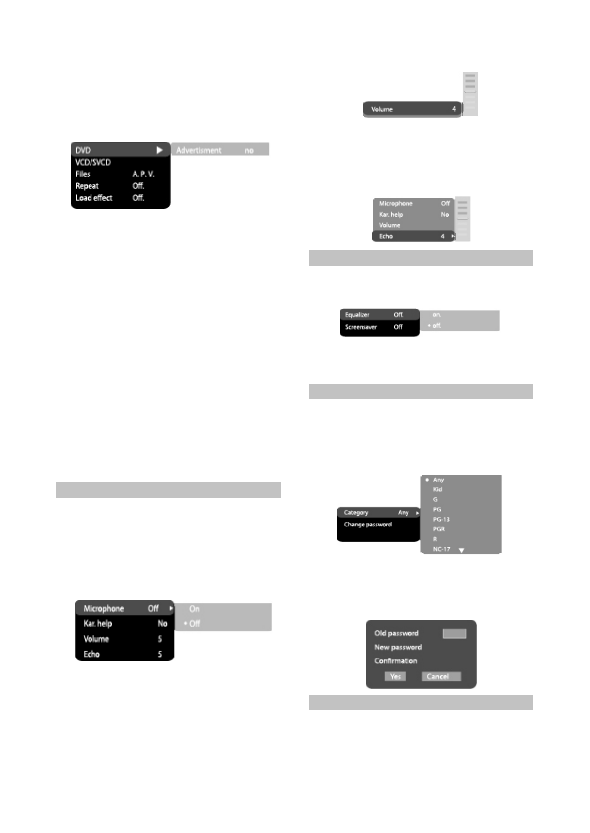
1.DVD
Advertisment skip: skip the unskippable
block while playing a DVD disc.
#Options: Yes, number
#Default option: No.
2.VCD/SVCD
PBS menu: PBC menu on/off
#Options: On, Off.
#Default option: On.
#If On option is set, while reproducing discs, a
menu will appear, in which you can select the
order of playing the disc content. If the Off
option is set, the reproducing of content is
performed in the order, in which it is recorded
on the disc.
3.Files: selection of reproduced files on the disc
#Options: Audio, Pictures, Video.
#Default option: A.P.V.
4.Repeat: file repeat mode
#Options: Off, Single, All.
#Default option: Off.
5.Load effect: type of transition from one JPEG
file to another.
#Options: Off, from Top, from Bottom.
#Default option: Off
2.4.6 Karaoke settings menu
1.Microphone: microphone on/off
#Options: On, Off.
#Default option: Off.
2.Kar.help: karaoke-disc playback mode
#Options: channels L, channels R, No ast, No
voc.
#Default option: Without solo.
3.Volume:
Microphone: microphone sound volume
level.
#Using the wheel adjust the microphone volume
level.
#Press the LEFT button to return to karaoke
settings menu.
4.Echo: echo level while playing the karaoke-
disc
#Adjust the echo level Using the cursor buttons.
#Press the LEFT button to return to karaoke
settings menu.
2.4.7 Preference settings
1.Equalizer: spectrum analyzer
#Options: On, Off.
#Default option: Off.
2.Sccreensaver: screen saver on/off
#Options: On, Off.
#Default option: On.
2.4.8 Family filter settings
1.Category: set-up of age restrictions to prevent
children fro seeing undesirable discs.
#Options: Any, Kid, G, PG, PG-13, PGR, R, NC-
17.
#Default option: Any.
2.Change password: set-up of a four-digit
password to change the level of age
restrictions.
#Default option: 7890
2.4.9 Initial settings menu
#Press the RIGHT key to enter the initial settings
menu, then select the desired item using the
cursor buttons and press OK key for
confirmation.
- 10 -

#While being in this menu section, you cannot
return to the previous level by pressing the
LEFT key.
2.4.10 Reset settings to default
Resetting all settings and restoring default
options, except age restrictions level and
password.
2.4.11 Exit settings menu
#Select the exit item using the UP/DOWN
buttons and press the OK key to exit the menu.
2.4.12 Channel delay set-up
Set-up of time delay in the surround
channel
Usually, time delay in the Dolby Digital
decoding system is preset to ensure best effect
while installing the Home Theater. However, in
case you wish to adjust your system more
precisely, please consult instructions given in
this manual. Set up of time delay for this device
is possible in both Dolby Digital and Dolby Pro
Logic modes...
To set the desired delay you have to know
the distance from the place where you are, to the
front speakers and Surround speakers as shown
in Fig.1. Consult Fig.2(Dolby Pro Logic mode)
and 3(Dolby Digital mode)in order to determine
the distance to Surround speakers (axis Y in the
figure)and the distance to the front speakers
(axis X in the figure). Crossing point of those two
lines on the chart will give the recommended
delay value.
Set-up of time delay in the central channel
Sometimes several people are listening to
the music, and the space is limited. In this case,
you can install three speakers(two front ones
and a central one)as shown in Fig.1 with the
distance to the listener being approximately the
same. The central channel delay is to be set at
“0”.
Should the central speaker be in close
proximity to left and right front speakers as
shown in Fig.2, of the central speaker be nearer
to listeners when compared with front speakers’
location, or the central speaker be nearer to the
listener by 1 foot, in all these cases you may set
the delay value for the central channel at 1 ms.
For instance, as shown in Fig.2, if the line C
is by 1 foot shorter than the lines R and L, the
delay value is to be set at 1 ms. If you sofa is
broad enough, and there are several listeners
sitting on it, it makes sense to locate the
speakers in one line, as shown in Fig.3 with the
delay value of the central channel to be set at “0”.
Finally, if it will be necessary to install the
central speaker behind the left and right front
speakers, the delay value shall be set at “0”.
2.4.13 “Night” mode
He Dolby Digital system provides an extremely
broad dynamic range of playback sound-from
gentle to roaring. It creates the presence effect,
especially while seeing motion pictures.
However, at night a powerful sound with a broad
dynamic range may give pleasure to you, but
disturb and annoy your family and neighbors. If
you just decrease the volume, you will
immediately notice that you ceased to hear, e.g.,
Dialogues as clear as you do at normal volume,
and such sound effects as rustle, whisper etc
have merely disappeared.
- 11 -

To avoid this, you just have to decrease the
volume of “loud”sounds by simultaneously
increasing the volume of “soft”sounds with the
volume of “average”sounds left unchanged, i.e.
Just decrease the dynamic range of sound
accompaniment. Only Dolby Digital system
provides for such a method of sound control. It
uses the principle of compressing the acoustic
signal’s dynamic range while recording;
therefore, while playing an inverse
transformation(volume expansion)takes place.
This is called “night” mode. The regulation limits
are restricted, however, to avoid distortions of
resultant signal.
Dolby Digital Dolby Pro Logic surround
Rear channel Stereo 20 Hz-20khz
Mono channel with limited friquency range(100 Hz-
7khz)
Low-frequency
channel(subwoofer)
Available, 20-120Hz N/a
Sound field distribution multivariate From left to right, from right to left, from front to rear,
from rear to front
Channels
6 Independent channels, each
reproducing its own signal at a time
4 segmented channels. Only one channel is decoded at
a time.
Creates an optimum sound field with
illusion of an equal distance from
listener to each speaker.
The most cost-efficient way to ensure high-quality
surround effect.
Allows adjusting the decompression
degree of an equal distance from
listener to ecach speaker.
Surround sound may be received from any signal
source.
Possilility of programmable control
of the decoder to transfer basses into
low-frequency channel in systems
equipped with broad-band speakers
and a subwoofer.
Compatible with existing and future two-
channel(stereo)formats.
Undoubted progress in sound
recording technology, especially
important for program directors, film
directors, sound engineers and actors.
Big progress in comparison with conventional stereo,
the world's most popular surround format.
Miscellaneous
2.5 Technical characteristics
Playback discs
Input
DVD-Video, Super VCD, VCD, DivX 4, DivX 5, DivX
Pro, XviD, CD-DA, CD+G, HDCD, MP3, WMA, Kodak
Picture CD, JPEG
2 MIC jacks
FM antenna input
AM antenna input
Stereo audio input(AUX)
DVD receiver
- 12 -
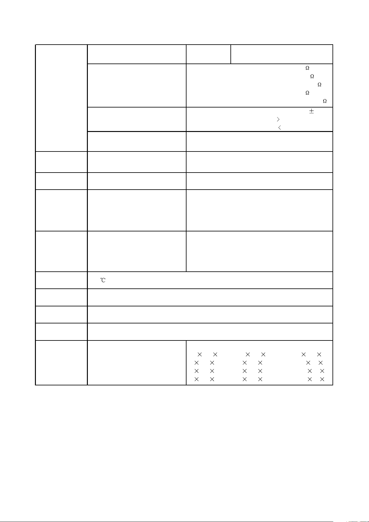
Output Audio output
Analog audio output: Stereo
Digital audio output: Coaxial, Optical
Video characteristics
Audio characteristics
Operating voltage
Power consumption
FM Tuner
Frequency range
Channel separation
AM Tuner
Frequency range
Speaker system
Output power RMS, 10% THD, 1 kHz
Subwoofer(40Hz)
Front channel
Rear channel
Center channel
Maximum power
Subwoofer
Front channel
Rear channel
Center channel
Operating
temperature
Operating humidity
Dimensions of
DVD-receiver
Weight of DVD-
receiver
Dimensions of
speakers
Subwoofer
Front channel
Rear channel
Center channel
40 50 50
20 20 20
20 20 20
20 20 20
DK1110SI DK1112SI DK1114SI
325 310 200 325 310 200 325 310 200
80 101 165 80 101 165 150 90 86
80 101 165 80 101 165 150 90 86
80 101 165 80 101 165 150 90 86
5-35
15-75%(no condensation)
60×380×350mm
3.4kg
Video amplitude: 1.0Vp-p(75 )
S-Video amplitde: Y:0.7vP-P(75 )
Component video amplitude: C:0.286vP-P(75 )
1.0vP-P(75 )
Cb/Cr:0.7Vp-p(75 )
Frequency response 20-20000Hz( 1 Db)
Signal-to-noise ratio 90(dB)
THD 1%
~220V,50/60 Hz
250W
87.5-108 MHz
>35dB
522-1611kHz
DK1110SI DK1112SI DK1114SI
25 25 25
12 12 12
12 12 12
12 12 12
DVD receiver
#We are permanently improving the quality of our products; hence the product’s design, functionality
and technical characteristics may be modified without prior notice.
#We do not guarantee that all discs can be played smoothly due to the disc quality, disc recording quality
and recording format.
- 13 -

3.1.1 Features of the player
Progressive scanning output to produce steadier and clearer pictures
Composite video, S-video and component video output. 5.1CH output
Digital picture adjustment to the sharpness, brightness, contrast, chroma and saturation of
pictures, gamma correction
Karaoke function. Built-in Dolby digital decoder
Hi-Fi stereo headphone output
FM/AM digital tuning function, capable of storing (memorizing) 20 FM/AM radio stations each
Power amplifier adopts high-performance large-power IC, with complete protection function and
perfect sound quality
Compatible with DIVX, MPEG4 format movie
Subwoofer adopts large-diameter bass unit with large-capacity body, with deep and dynamic
bass effect
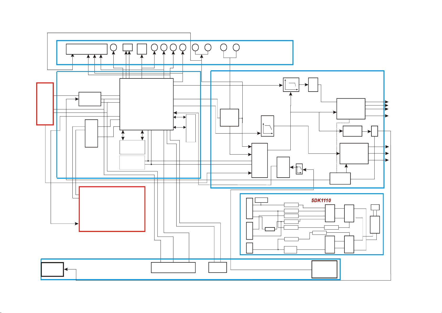
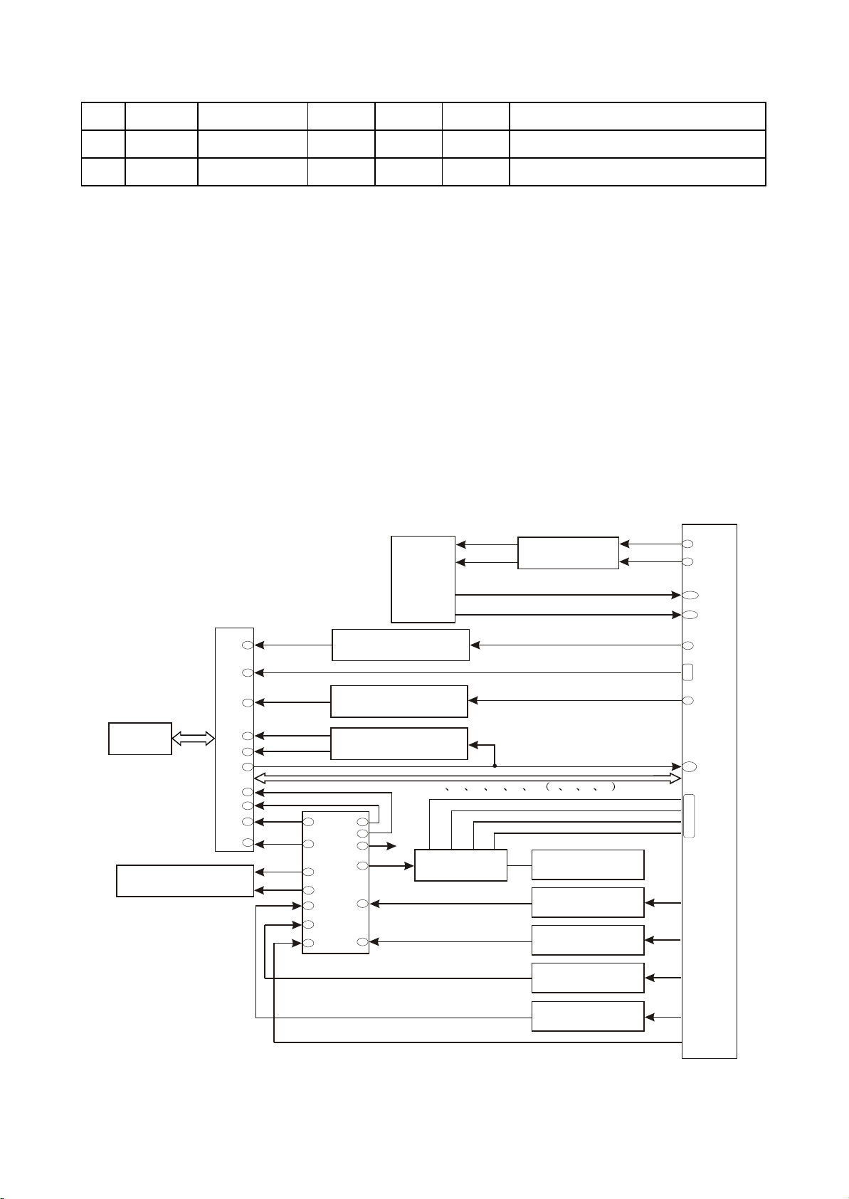
3.1.2 Block diagram of the player
This player is composed of decode & servo board, power amplifier board, input/output board, panel,
headphone board, tuner, power board and loader. Block diagram of the player is shown in the figure
3.1.2.1. Except that power board is not shown, other signal flow is shown in the figure basically. Main
function of loader is to read disc information and transmit to MT1389E, MT1389E fulfils servo function
through Ba5954 on decode board and other subsidiary circuit; and ensures normal working of loader
through other circuits. FLASH on decode board is to save system program, SDRAM is to save program
when the player is working and read sound and picture information from disc to ensure smooth output.
The main function of power amplifier board is to perform DA conversion and amplification of analog
signals to output 5.1CH and ensure normal working of external speaker. The main function of AV board
is to output various audio and video signals. This player is also with headphone and microphone to meet
client’s requirements. In addition, there is external sound input , power amplifier board of this player may
be used to amplify power to facilitate to output to speaker. Tuner in this player also makes it have tuning
function.
Chapter Three Principle and Servicing
Section One Principle of the Player
- 14 -
SCART
Coaxial
Cr/Pr Cb/Pb AUX-in
MIX-out
COMP
1DVR938-3
C
Y
SPDIF
Y1
U
V
Y
OpticalS-video
Composite video
MIC1/MIC2
LRSWMUT/SCMUT
TDA8947
PT2314
AUXR/AUXL
TROUT/TLOUT
SL/SR/C
SW
SW3
LF/RF
SWOUT+
SWOUT-
LOUT
ROUT
LM4580
HL/HR
OK
SROUT
COUT
SLOUT
12V1
4DK1110
LO/RO
LPF/
amplifying
M62429
LRSWM
SCM
TDA8947
CS5340
Add/LPF/amplifying
LPF/amplifying
Add/LPF/amplifying
Mute
Mute control
circuit
MT1389E
24C02
FLASH
SCL
SDA
CD4094
SDATA0
VSDA/DTSDI
VSCK/DTSCL
2DK1110
Gating signal
Data/address line
Data/
address line
SDRAM
D5954
Mute control signal
Main axis/focus/trace/feed
Loader
Disc data/laser power control identification
VSTB
J3
J4
6DK1110
9DK1110
SN1692
BDK1 110
Digital
potentiometer
MIC socket
Headphone
socket
Tuner
A+5V
De-panel
De-decode board
De-power amplifier
board
De-power amplifier
board
~220V
D+5V
D+3.3V
-12V
+12V
+22V
5L0380
KAIM0880
Transformer
Transformer
Voltage stabilizing
and filtering
Voltage stabilizing
and filtering
Photoelectric
coupler
sampling
Voltage stabilizing
the second time
Bridge
rectification
Voltage stabilizing
and filtering
Voltage stabilizing
and filtering
Voltage stabilizing
and filtering
Photoelectric
coupler
Sampling
Figure 3.1.2.1 Block diagram of the player
- 15 -
SL+
SL-
LIMIT
GND
SP+
SP-
1
2
3
4
5
6
1
2
3
4
5
LO-
LO+
TRO
GND
TRI
XS302
Loader board
Loader
XS303
Software
upgrading
X110
Headphone
board
1
2
3
HR
AGND
HL
4
HDET
1
2
3
MIC1
AGND
MIC2
MIC
board
X100
NC
DTS_CE
DTS_DL
DTS_CL
DTS_DO
DGND
NC
NC
NC
+12V
TLOUT
AGND
TROUT
13
7
8
9
10
11
12
1
2
3
4
5
6
Tuner
XP102
1
2
3
4
5
D+5V
D-GND
D+3V3
A-GND
A+5V
1
2
3
4
5
D-GND
D+5V
FL+
FL-
-21V
XS505
Power
board
XP203
1
2
3
A+5V
A+5V
A-GND
4
A+5V
5
6
A-12V
A-GND
7
A+12V
XS504
P+28V
P+28V
GNDP-
1
2
3
GNDP-
4
XS503
IR
CLOCK
STB
DATA
J3
J4
1
2
3
4
5
6
XS100
Front panel
+5V
GND
1
2
X100
AGND
R
C
L
DTS_CE
AGND
SL
GND
SR
SW
SDA
HDET
OK-DAT
DTS_DO
DTS_CL
DTS_DI
GND
SBCLK
SLRCLK
SCMUT
GND
SCL
P_RST
SCL1
LRSWMUT
SDAT
GND
SMCLK
25
26
27
28
20
21
22
23
24
13
14
15
16
17
7
8
9
10
11
12
1
2
3
4
5
6
18
19
Power amplifier board
XS601
XS100
1
2
3
MIC1
AGND
MIC2
1
2
3
HR
AGND
HL
4
HDET
X110
13
7
8
9
10
11
12
1
2
3
4
5
6
NC
DTS_CE
DTS_DL
DTS_CL
DTS_DO
DGND
NC
NC
NC
+12V
TLOUT
AGND
TROUT
XS101
1
2
3
DV33
DV33
DGND
4
+5V
5
6
-12V
AGND
7
+12V
CON7
PVCC
PVCC
GND
1
2
3
GND
4
XP100
7
8
6
1
2
3
4
5
AUXR
AUXL
+12V
+5V
RO
AGND
LO
AGND
Input/output board
XP206
AUXR
AUXL
7
8
6
+12V
D+5V
RO
AGND
LO
AGND
1
2
3
4
5
13
7
8
9
10
11
12
1
2
3
4
5
6
SPDIF
Y5
Y6
HSYNC
VSYNC
VDATA3
GND
Y1
Y2
GND
Y3
GND
Y4
XP401
Speaker
1
2
3
4
Dv33
RXD
TXD
GND
XS202
XS302
LO-
LO+
TRO
GND
TRI
1
2
3
4
5
SL+
SL-
LIMIT
GND
SP+
SP-
1
2
3
4
5
6
XS303
IR
VSCK
VSTB
VSDA
J3
J4
1
2
3
4
5
6
XS201
VCC
GND
DV33
GND
AVCC
1
2
3
4
5
XP203
XS206
XS207
Decode board
24PIN
IEC958
B/C
R/Y
HSYNC#
VSYNC#
VDATA3
GND
R/Y
B/C
GND
CVBS
GND
G
13
7
8
9
10
11
12
1
2
3
4
5
6
25
26
27
28
20
21
22
23
24
13
14
15
16
17
7
8
9
10
11
12
1
2
3
4
5
6
18
19
AGND3
R
C
L
DTS_CE
AGND
SL
GND
SR
SW
SDA
HDET
OK-DAT
DTS_DO
DTS_CL
DTS_DI
GND
SBCLK
SLRCLK
SCMUT
AGND
SCL
P_RST
SCL1
SDAT
GND
SMCLK
LRSWMUT
XS301
XS101
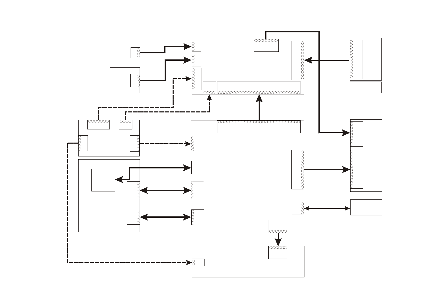
3.1.3 PCB board composition diagram of the player
PCB board composition diagram of the player is shown in the figure 3.1.3.1:
Figure3.1.2.1PC Bboard block diagram of the player
- 16 -

3.1.4 Introduction to IC used in this player
Introduction to IC used in DK1110SI is shown in the following table:
PCB semi-finished
product
IC model Location Function
MT1389E U201 Decode chip
24C02 U202 EEPROM
HCU04 U205 Phase inverter
LM1117 U206 Precision voltage stabilizer
29LV160BE U207 16M FLASH
HY57V641620HGT-7 U208 64M SDRAM
CD4094 U213 Serial and parallel connection conversion
D5954 U301 Servo drive
4558 N101 N102,N103,N104 Audio amplifying
M62429 N105 Volume control
TDA8947J N106,N110 Digital pow er amplifier
RC4580 N107 Audio amplifying
CS5340 N108 A/D conversion
PT2314 N111 Audio proc essing
PT6961 N100 Panel control IC
HS0038A2 N101 Remote control rec eiver
KA5L0380R U501 Power sw itch IC
HS817 U502,U506 Photoelectric coupler
TL431 U503,U507 Precision voltage stabilizer
LM7805 U504 Voltage stabilizing tube
KA1M0880BTU U505 Power sw itch IC
Powr board
Decode board
Pow er amp lifie r
board
Mainpanel
- 17 -

3.2.1 Loader signal explanation
Loader signals explanation is shown in the following table:
Section Two Unit Circuit Principle
Pin Name
Signal flow
direction
DVD disc CD disc No disc Function description
1 F- Input loader 2.52 2.34 0.46
2 F+ Input loader 2.49 2.49 0.93
3 T+ Input loader 2.53 2.51 0.94
4 T- Input loader 2.58 2.51 0.93
5 C Input MT1389 2.2 2.25 2.04 Disc data signal
6 D Input MT1389 2.2 3.2 2.04 Disc data signal
7 IOA Input MT1389 0.01 3.2 3.21
Disc identification signal, CD is 3.3V, DVD
is 0V
8 RF Input MT1389 2.21 2.53 1.28 The sum of disc data signal
9 A Input MT1389 2.17 2.22 2.04 Disc data signal
10 B Input MT1389 2.19 2.27 2.04 Disc data signal
11 F Input MT1389 2.07 2.44 2.03 Supplementary signal us ed in trace
12 GND Ground 0.01 0.01 0 Grounding
13 V20 Input loader 2.04 2.06 2.03 Reference voltage
14 Vcc Input loader 5.04 5.04 5.02 Supply voltage for loader
15 E Input MT1389 2.06 2.45 2.03 Disc data signal
16 Blanking haning in air 0.01 0 0 unused
17 VR-CD Input loader 0.21 0.01 0
Through the handling inside loader, make
sure MD11 is 180mV when reading CD
18 VR-DVD Input loader 0.01 0.2 0
Through the handling inside loader, make
sure MD11 is 180mV when reading DVD
19 LD-CD Input loader 0.09 2.1 0 CD laser power control signal
20 MDI I Input MT1389 0.21 0.2 0
CD and DVD laser power monitoring
signal
21 HFM Input loader 5.04 5.04 5.02
High frequency overlapping signal
produces laser with different wave length
inside loader
Focus error signal is added to two sides of
pick-up focus coil
Trace error signal is added to two sides of
pick-up trace coil
- 18 -
22 Blanking unused 0.01 0.1 0
23 LD-DVD Input loader 2.21 0.1 0 DVD laser power control signal
24 GND unused 0.01 0.01 0 Grounding
Note: 1. When reading DVD, there are only A, B, C, D signals
2. When reading CD, there are A, B, C, D, E, F signals.
3. RFO=A+B+C+D.
4. Focus error signal=(A+C)-(B+D) Trace error signal=E-F.
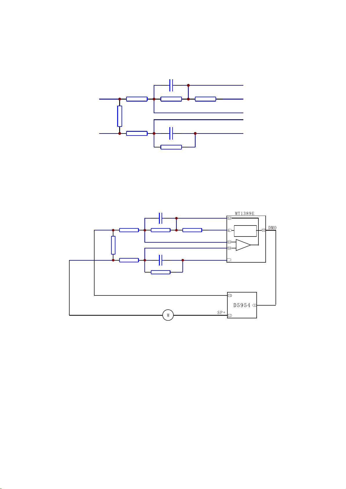
3.2.2 Servo circuit
1. DK1110SI adopts SANYO HD62 loader and MTK decode solution (MT1389E+FLASH
(16M)+SDRAM (64M)). Its servo circuit is mainly composed of front signal processing and digital servo
processing, digital signal processing IC MT1389E and drive circuit D5954, in which MT1389E is also the
main part of decode circuit, shown in the figure 3.2.2.1:
Figure 3.2.2.1 Servo circuit block diagram
Loader
2
23
20
19
18
17
1
4
3
XS301
DVD laser power control
VCD laser power control
Disc identification
circuit
Open/close
electric
machine
and
detect
switch
Open/close circuit
TROPEN
TRCLOSE
TRIN
TROUT
39
99
150
148
22
20
21
23
7
IOA
ABCDEFabcd
15
20
17
D5954
13
14
Feed electric
machine on loader
SL+
SL-
12
SP-
SP+
Main axis
braking circuit
Main axis electric
machine on loader
5
1
18
23
26
28
Integration circuit
Integration circuit
Integration circuit
Integration circuit
90
34
43
35
36
OPO
ADIN
OP-
OP+
11
MT1389E
- 19 -

2. Working principle: after powering on or disc in, according to IOA signal, disc identification circuit
decides through which path of variable resistor the laser detecting diode gets path to the ground,
meanwhile MT1389E decides whether DVD laser or VCD laser is emitted according to IOA signal, which
can be fulfilled through laser power control circuit. When IOA is high level (3.3V), Mt1389E pulls LOD1 of
Q302 base electrode in laser tube power control connected to VCD down to about 2.2V to make Q302
on and to make VCD laser tube emit beam; then decides whether to pull up or pull down LOD1 according
to voltage after the feedback from MDI1 to control the power of light emission diode. Similarly, when IOA
is low level (0V), MT1389E pulls LOD2 of Q301 base electrode in laser tube power control connected to
DVD down to about 2.2V to make Q301 on and to make DVD laser tube emit beam; then decides
whether to pull up or down LOD2 according to the voltage after the feedback from MDI1.
After loader reading disc information, A, B, C, D, E, F signals are sent out to Mt1389E (DVD only
has A, B, C, D signals), and then inputted from pin 2~11, 18, 19 of MT1389E. After being amplified and
processed by the pre-amplifier inside MT1389E, now signals are separated to two part s for processing
inside Mt1389E.
After being processed by digital servo signal circuit inside MT1389E, one part of signal form
corresponding servo control signals and output FOO, TRO, DMO, FMO digital servo control signals from
pin 42, pin 41, pin 37, pin 38 of MT1389E respectively, then change into analog servo control signal
FOSO, TRSO, DMSO, FMSO through integration circuit composed by resistor capacitor, and send to
driver circuit D5954 for amplification to bring along focus winding, trace winding, main axis electric
machine and feed electric machine after drive amplification. Among these, focus and trace servo are
used to correct objective position accurately; feed servo is used to bring along laser head to make radial
large-scale move which belongs to the preliminary adjustment to pick-up position; and main axis servo is
used to control main axis electric machine to make it read signals in means of constant linear velocity
and bring along disc to rotate.
After processing of amplification by VGA voltage control amplifier and equalization frequency
compensation inside MT1389E, another part of signals are changed into digital signals through internal
A/D converter. When loader is reading CD/VCD signals, these signals are conducted EFM demodulation
inside MT1389E, and then outputted to latter stage for AV decoding after finishing CIRC (Cross-
Interleaved Reed-Solomon Code) error correction inside. When loader is reading DVD signals, these
signals are conducted ESM demodulation inside MT1389E, and then sent to latter stage for decoding
after finishing RSPC error correction inside.
The other part of servo is open/close disc tray circuit. After panel or remote controller emits
open/close disc tray signal to MT1389E, in usual conditions, TROPEN and TRCLOSE sent out by pin 39,
99 of Mt1389E are both low level, when signal of “open” comes, after Mt1389E makes disc stop rotating
through main axis braking circuit, TRCLOSE is set high to make open/close electric machine on loader
frame run to bring along dist tray to eject. After disc tray ejecting to proper signal of opening to proper
position (TR_OUT) is set high level (0V) through the detecting switch on loader frame, MT1389E pulls
- 20 -
down TRCLOSE and open/close electric machine stop running. When MT1389E receiving “close” signal,
TROPEN is set high level by MT1389E, open/clode electric machine tuns conversely to bring along disc
Tray to close. After disc tray closing to proper position, signal of closing to proper position (TR_IN) is set
low level through the detecting switch on loader frame, MT1389E pulls down TROPEN and electric
machine stops running to finish “close” process.
3. Explanation to servo terms
(1) FOO: for disc make differences, and when rotating disc may probably move upwards or
downwards slightly to make the focus of laser emitted by laser head cannot justly fall on data pit of disc,
now focus point of objective lens is required to adjust to make focus aim at data pit exactly. The acts are
mainly to make objective lens move upwards and downwards.
(2) TRO: data information is saved in disc in form of tracks. When disc is rotating, disc deviation will
produce, now laser head is required to adjust. In this process, objective lens makes forward and
backward movement with small moving range.
(3) FMO: similar to acts of trace, the acts of feed are larger than those of trace. Feed conducts a
large scale movement firstly, and then trace moves slightly in this range. Feed moves for a while, and
does not move for another while; but trace moves all the time. Feed is rough adjustment and trace is fine.
And acts are obvious when power on and selecting track.
(4) DMO: it is the top that holds up disc. Its rotation speed decides that of disc. Its rotation is
generated by an individual DC electric machine, in which rotation speed of DVD is twice over that of CD.
4. Key point voltage (unit: V) is shown in the following table:
Name
w hen reading
disc nor mally
w hen opening door w hen closing door
w hen no disc
in
TRO PEN 0
There is about 3.3V pulse w ith 1S at
the moment of opening door
0 0
TRCLO SE 0 0V
There is about 3.3V pulse w ith 1S at the
moment of opening door
0
TROUT 3.41V 3.3V 0V 0V 3.3V 3.3V
TRIN 0 0V 3.3V 3.3V 0V 0
OPO 2.61V 2.75V 2.64V 2.61V
ADIN 2.61V 2.76V 2.61V 2.61V
OP+ 1.66V 1.81V 1.27V 1.81V
OP- 1.85V 2.12V 1.47V 2.04V
- 21 -
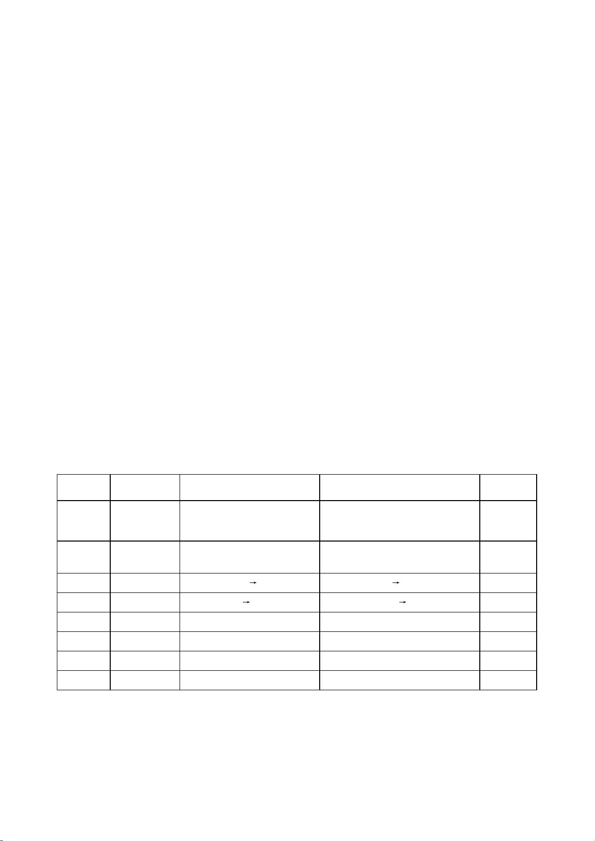
3.2.3 Mute circuit
DK1110SI mute control circuit includes power-on mute control, power-off mute control and usual
mute function.
1. Power-on mute is shown in the figure 3.2.3.1. When voltage of pin 5, 10 of power IC TDA8947 is
lower than power supply voltage 3.5V of this IC, this IC enters MUTE mode, from 0 to 0.8V, it is STANBY
mode.
When power on, due to the function of Tc147 charge, V102 cuts off at the beginning, V103 is on,
HERDM is low level, shown in the figure 3.2.3.2. Seen from the figure, when HARDM is low, SCM,
LRSWM are pulled down to fulfil power-on mute.
TC147
22uF/25V
V102
C9014
VD111
5.1V
VD110
1N4148
R178
100K
R180
47K
PVcc
V103
8050
R181
10K
HARDM
R179
47K
+12V
Figure 3.2.3.1 Power-on mute circuit
2. Usual mute: 1389 sends out control signal SCMUT, LRSWMUT to control the on of triode V101,
V104 to make SCM, LRSWM be low level to fulfill mute function.
3. Power-off mute: V100 realizes power-off mute function. When +12V power failure, Tc136 still
keeps high level, now base electrode of V100 is low, V100 is on, base electrode of V101, V104 gets high
level and they are on to realize power-off mute function.
LRSWMUT
SCMUT
V101
9014
SCM
V104
9014
R166
10K
LRSWM
R165
10K
C146
104
C156
104
VD108
1N4148
VD109
1N4148
HARDM
VD106
VD112
1N4148
VD105
R162
220
+12V
R163
22K
R164
22K
V100
8550
TC136
16V/100U
VD107
1N4148
VD120
1N4148
12V1
VD128
1N4004
PVcc
Figure 3.2.3.2 Mute circuit
- 22 -
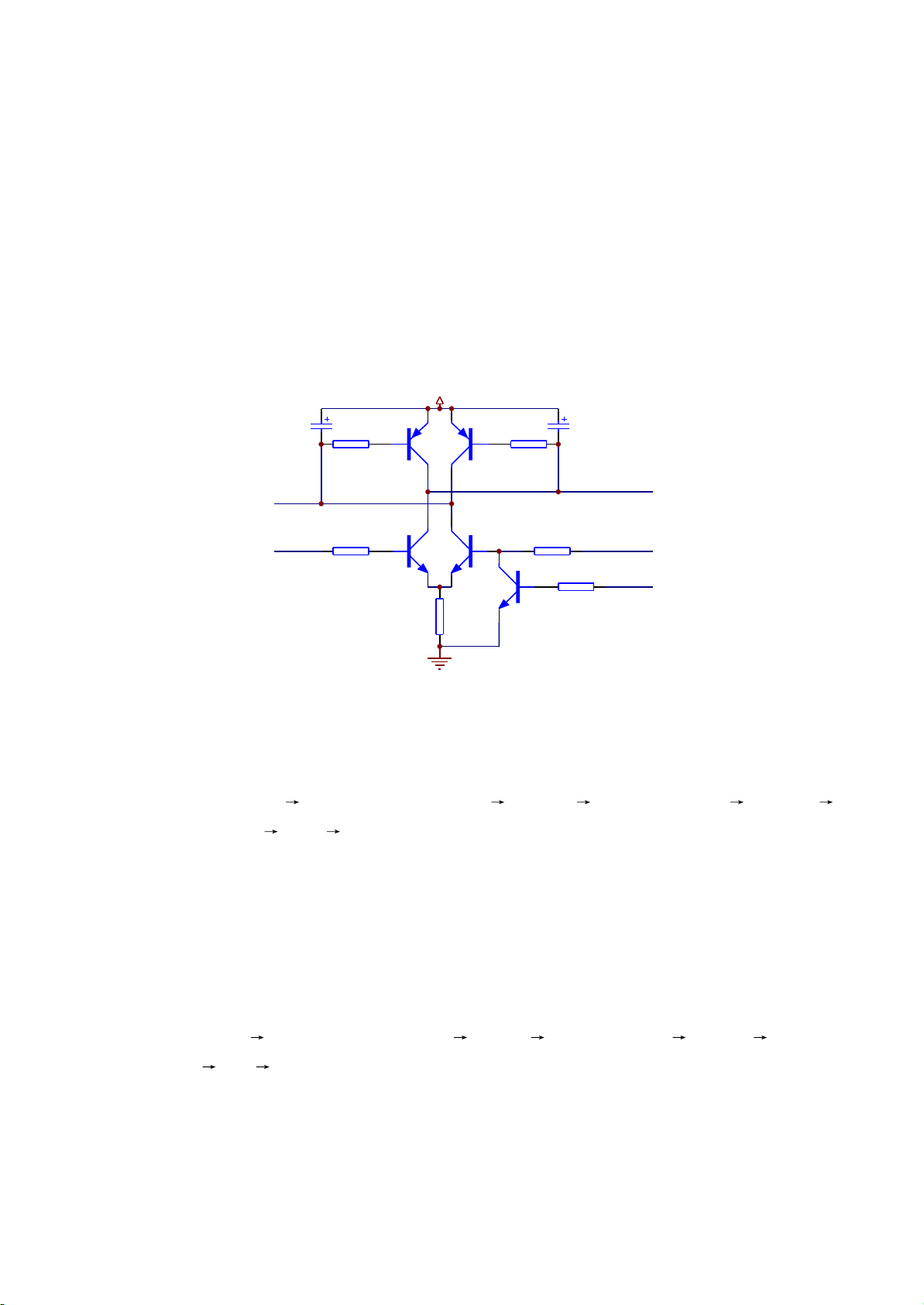
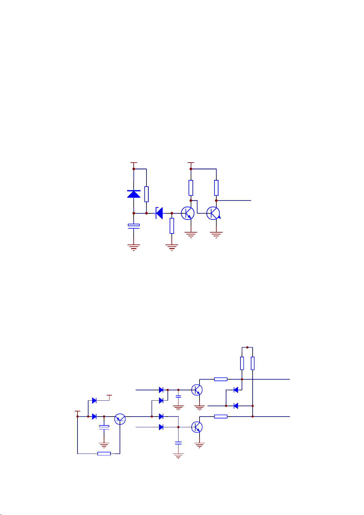
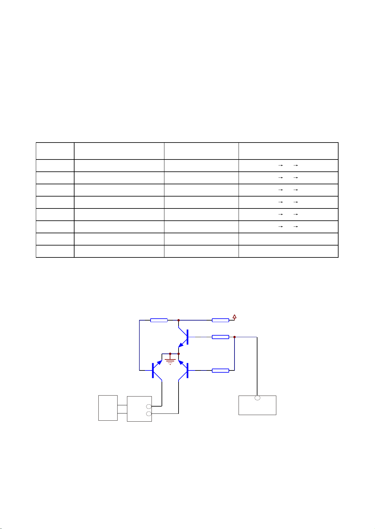
Figure 3.2.4.1 Open/close door circuit diagram
R325
510R
R327
510R
Q309
8050D
Q308
8050D
Q306
8550D
Q307
8550D
R323
1.5K
R324
1.5K
R339
10K
R326
2.2R\1/4W
TC305
47uF/16V
TC306
47uF/16V
LOAD+
LOAD-
MO_VCC
TRCLOSE
Q310
9014-S
TROPEN
TROPEN
2. Working principle:
Open door, VCC Q306CE electrode is on LOAD+ electric machine LOAD-
Q309CE electrode is on R326 ground
When action of opening door is not performed, pin 99 and 39 of MT1389E are low level. When
opening door, pin 99 of MT1389E send out a high level, Q309 is on, collector electrode of Q309 changes
to low level, LOAD- changes to low level, base electrode of Q306 changes to low level, Q306 is on,
collector electrode of Q306 changes to high level and LOAD+ changes to high level.
Close door: VCC Q307CE electrode is on LOAD- electric machine LOAD+ Q308CE
eklectrode is on R326 ground
When closing door, pin 39 of Mt1389 sends out a high level, Q308 is on, collector electrode
changes to low level, LOAD+ is low level, base electrode of Q307 changes to low level through R324,
Q307 is on, collector electrode of Q307 changes to high level, LOAD- changes to high level.
4. When inserting headphone, friction will produce noise, so these noise should be filtered. When
inserting, HDET pin is grounded and low level, which is sent to 188 pin of 1389E, 1389E receives HDET
low level and sends out control signal to TDA8947, output stops and mute function is realized.
Note: when inserting headphone, mixed left/right channel on AV board has output, audio signals on
power amplifier board have no output; when in mute, all has no output.
3.2.4 Open/close door circuit
1. Open/close door circuit diagram is shown in the figure 3.2.4.1:
- 23 -
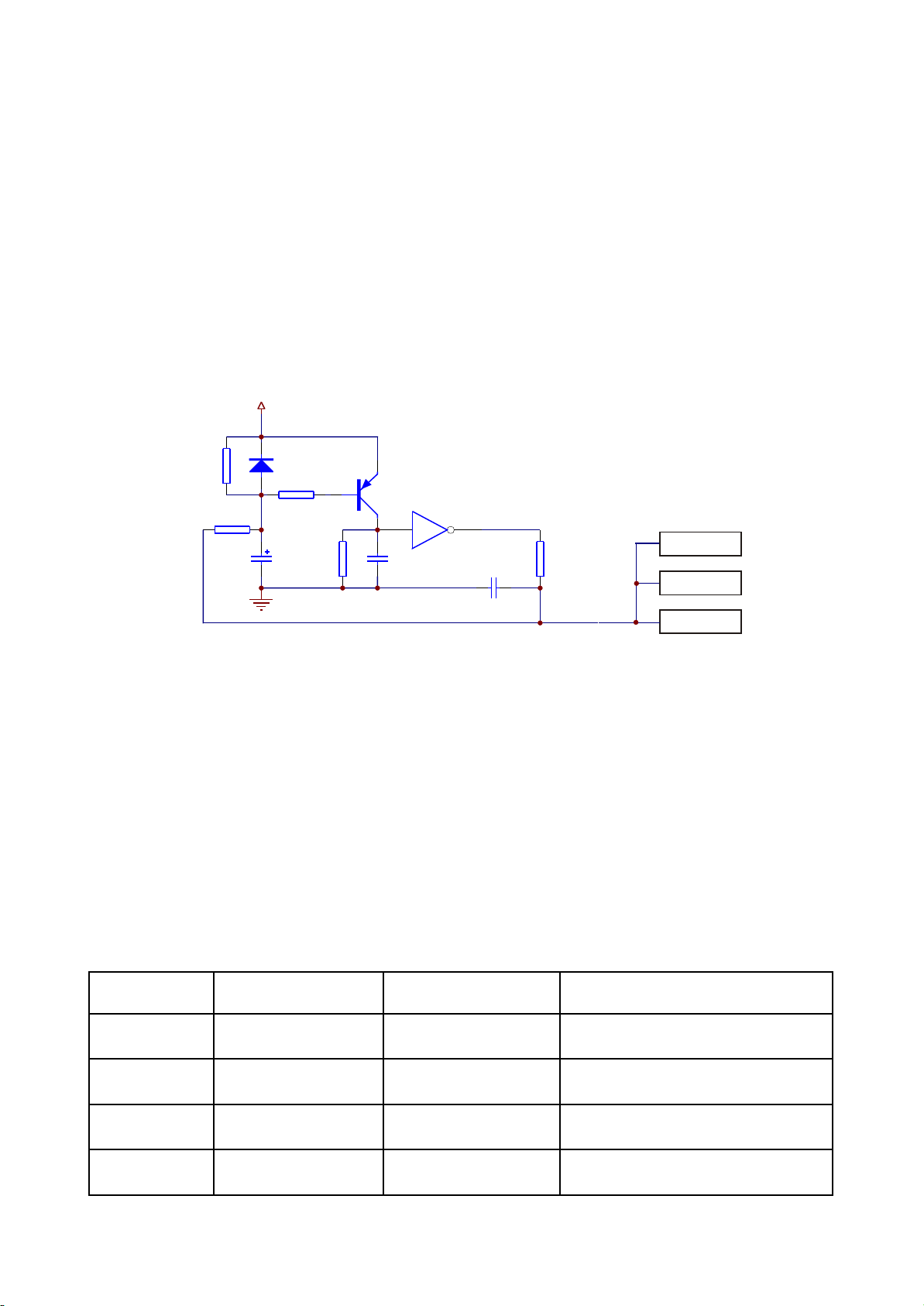
Figure 3.2.5.1 Reset circuit diagram
C1003
225
TC320
100uF/16V
R2011
75K
R2023
47K
R2024
FLASH
5 6
U205C
HCU04
URST#
DV33
R2022
0R(DNS)
Q320
8550D
R2025
1K
D215
1N4148
C1004
102
A
B
D
C
33R
MT1389E
Cs5340
12
101
9
2. Working principle: when power on, voltage on two ends of capacitor Tc320 cannot change
suddenly, anode of capacitor begins charging from 0V, now triode Q320 is on, pin 5 of input end of phase
inverter U205C (HCU04) is high level, pin 6 of output end is low level and performs reset to chip
MT1389E, FLASH, TAS5508 and Cs5340; when capacitor charge is close to 3.3V, triode Q320 cuts off,
pin 5 of input end of phase inverter is low level, phase inverter outputs high level from pin 6 and system
reset finishes.
3. Key point voltage (unit: V) is shown in the following table:
The function of Q310 is to interlock TRCLOSE and TROPEN signals to ensure that the two are not
high level at the same time. When the two are high level input, the on of Q310 makes base electrode of
Q309 be low level to ensure the normal working of open/clode door circuit, electrolyte capacitor TC306
and TC305 are used to prevent the sudden change of two ends of in/out control electric machine and
make the action gentle.
3.2.5 Reset circuit
1. Reset circuit is shown in the figure 3.2.5.1:
Key point Position Voltage Remark
DV33 (point A) Diode D215 cathode 3.3V
Af ter pow er of f, TC320 discharge c urrent f rom
this point
point B Diode D215 anode Af ter reset finishes , 3.3V
Af ter res et finishes , voltage increases to 3.3V
fr om 0V
point C Phase inverter pin 5 Af ter reset finishes , 0V
Af ter res et finishes , voltage decreases to 0V
fr om 3.3V
URST# (point D) Joint place of R256 and R253 Af ter reset finishes , 3.3V
Af ter res et finishes , voltage increases to 3.3V
fr om 0V
- 24 -
R321
1R
R320
150K
R319
150K
R322
680K
R317
680K
R318
0R
C307
222
ADIN
OP-
OP+
V1P4
SP-
OPO
C308
222
SPL-
3.2.6 Main axis braking control circuit
1. Main axis braking control circuit is shown in the figure 3.2.6.1:
Figure 3.2.6.1 Mai axis braking control circuit
Equivalent circuit is shown in the figure 3.2.6.2:
Figure 3.2.6.2 Main axis braking control equivalent circuit diagram
Internal
processing
3
R321
1R
R320
150K
R319
150K
R322
680K
R317
680K
R318
0R
C307
222
ADIN
OP-
OP+
V1P4
SP-
OPO
C308
222
SPL-
40
2. In order to prolong the usage life of electric machine and increase the influence of start-up
current to electric machine, when disc is in, R&D personnel design main axis electric machine into
running state all the time, even though STOP button is pressed. Thus, when pressing OPEN button, a
braking signal is required to make main axis electric machine stop rotating immediately to fulfill door
opening in short period.
During the course of playing, if OPEN button is pressed, main axis braking signal disappears, but
main axis electric machine is still in rotating state due to the function of inertia, now the inductive
electromotive force that produces from the rotation of electric machine achieves inductive voltage on
- 25 -
sampling resistor R321, through resistor R319, R320 with pin 35, 36 of MT1389E, after being processed
and amplified inside, output from pin 34, then through R318, send to pin 47 of MT1389E, through
MT1389E internal D/A conversion and relevant processing, pin 37 of MT1389E outputs an instant
electric machine reverse braking signal to make main axis electric machine speed down, when
MT1389E detects that disc stops rotating, disc tray will be out to ensure that disc will not rotate when
door opens.
3. Key point voltage (unit: V) is shown in the following table:
Key point Position Normal w orking voltage (V) Voltage var iation when opening door (V )
SP+ pin 11 of D5954, pin 5 of XS303 3.79 3.79 0.70 1.80
SP- pin 12 of D5954, pin 6 of XS303 1.38 1.38 3.40 1.80
OP+ MT1389E pin 36/B 1.38 1.38 3.10 1.80
OP- MT1389E pin 35/A 1.53 1.53 3.08 1.98
OPO MT1389E pin 34/C 2.44 2.44 0.40 2.50
ADIN MT1389E pin 43/D 2.44 2.41 0.41 2.44
DMSO D5954 pin 5 1.42 1.42
VIP4 MT1389E pin 40 1.41 1.41
Figure 3.2.7.1 Disc identification circuit
2. Working principle: the function of disc identification circuit is to recognise the disc inserted into
loader to judge whether the disc is VCD or DVD to make the relevant control action. When disc is
inserted, decode servo control IC MT1389E defaults disc to be DVD, pin 90 of MT1389E sends out a low
R309
10K
R308
100K
R311
10K
R310
100K
Q303
2SK3018-S
Q304
2SK3018-S
Q305
3904-S
IOA
AVCC
Loader
XS301
MT1389E
90
17
18
3.2.7 Disc identification circuit
1. Disc identification circuit is shown in the figure 3.2.7.1:
- 26 -
 Loading...