


MP-112
Installation Manual
Version 6.6
April 2012
Document #: LTRT-59815
MediaPack
TM
Series
MP-11x & MP-124
Analog VoIP Gateways


Version 6.6 3 April 2012
Hardware Installation Manual Contents
Table of Contents
1 Introduction ......................................................................................................... 7
2 MP-11x Hardware Installation ............................................................................ 9
2.1 Physical Description ................................................................................................. 9
2.1.1 MP-11x Front Panel (LEDs Description) ................................................................... 9
2.1.2 MP-11x Rear Panel (Ports Description) .................................................................. 10
2.2 Unpacking and Checking Package Contents ......................................................... 10
2.3 Mounting MP-11x ................................................................................................... 11
2.3.1 Desktop Mounting ................................................................................................... 12
2.3.2 Wall Mounting ......................................................................................................... 12
2.3.3 19-inch Rack Mounting ........................................................................................... 12
2.4 Cabling MP-11x ...................................................................................................... 14
2.4.1 Connecting MP-11x to the Ethernet Network ......................................................... 14
2.4.2 Connecting MP-11x to FXS Interfaces.................................................................... 15
2.4.3 Connecting MP-11x to FXO Interfaces ................................................................... 16
2.4.4 Connecting MP-11x to Analog FXS Lifeline Phone ................................................ 17
2.4.5 Connecting MP-11x to Computer for Serial Communication .................................. 18
2.4.6 Connecting MP-11x to Power ................................................................................. 20
3 MP-124 Hardware Installation .......................................................................... 21
3.1 Physical Description ............................................................................................... 21
3.1.1 MP-124 Front Panel ................................................................................................ 21
3.1.1.1 Reset Pinhole Button ............................................................................... 21
3.1.1.2 LEDs Description ..................................................................................... 21
3.1.2 MP-124 Rear Panel ................................................................................................ 22
3.2 Unpacking and Checking Package Contents ......................................................... 23
3.3 Mounting MP-124 ................................................................................................... 24
3.3.1 Desktop Mounting ................................................................................................... 24
3.3.2 19-inch Rack Mounting ........................................................................................... 24
3.4 Cabling MP-124 ...................................................................................................... 26
3.4.1 Power Surge Protection and Grounding ................................................................. 27
3.4.2 Connecting MP-124 to the Ethernet Network ......................................................... 29
3.4.3 Connecting MP-124 to FXS Interfaces ................................................................... 30
3.4.4 Connecting MP-124 to a Computer for Serial Communication ............................... 32
3.4.5 Connecting MP-124 to Power ................................................................................. 33
3.4.5.1 AC Power Supply..................................................................................... 33
3.4.5.2 DC Power Supply .................................................................................... 34

Hardware Installation Manual 4 Document #: LTRT-59815
MediaPack Series
List of Figures
Figure 2-1: MP-11x Front Panel (e.g., MP-118) ...................................................................................... 9
Figure 2-2: MP-11x Rear Panel (e.g., MP-118) ..................................................................................... 10
Figure 2-3: MP-11x Underside ............................................................................................................... 11
Figure 2-4: 19-inch Rack Shelf for MP-11x ........................................................................................... 12
Figure 2-5: MP-11x Rack Mount Installation ......................................................................................... 13
Figure 2-6: RJ-45 Connector Pinouts for Ethernet Connecti on ............................................................. 14
Figure 2-7: Connecting to the Ethernet ................................................................................................. 14
Figure 2-8: RJ-11 Connector Pinouts for FXS Interface ........................................................................ 15
Figure 2-9: Connecting FXS Interfaces ................................................................................................. 15
Figure 2-10: RJ-11 Connector Pinouts for FXO Interface ..................................................................... 16
Figure 2-11: Connecting FXO Interfaces ............................................................................................... 16
Figure 2-12: RJ-11 Lifeline Splitter Connector Pinouts ......................................................................... 17
Figure 2-13: Lifeline Cabling (Using Splitter Cable) for FXS-Only Devices ........................................... 17
Figure 2-14: Lifeline Cabling for FXS and FXO Devices ....................................................................... 18
Figure 2-15: PS/2 to DB-9 Adaptor Connector Pinouts ......................................................................... 18
Figure 2-16: PS/2 Connector Pinouts .................................................................................................... 18
Figure 2-17: Connecting the Serial Port ................................................................................................ 19
Figure 2-18: Connecting to the Power Supply ....................................................................................... 20
Figure 3-1: MP-124 Front Panel ............................................................................................................ 21
Figure 3-2: Rear Panel of MP-124 AC Powered Model ......................................................................... 22
Figure 3-3: Rear Panel of MP-124 DC Powered Model ........................................................................ 22
Figure 3-4: MP-124 Desktop Mounting .................................................................................................. 24
Figure 3-5: MP-124 with Brackets for Rack Installation ......................................................................... 24
Figure 3-6: Grounding and Power Surge Protection ............................................................................. 28
Figure 3-7: RJ-45 Connector Pinouts for Ethernet Connecti on ............................................................. 29
Figure 3-8: Connecting to the Ethernet ................................................................................................. 29
Figure 3-9: 50-pin Telco Connector ....................................................................................................... 30
Figure 3-10: MP-124 in a 19-inch Rack with MDF Adaptor ................................................................... 31
Figure 3-11: MP-124 RS-232 Connector Pinouts .................................................................................. 32
Figure 3-12: MP-124 Serial Cabling ...................................................................................................... 32
Figure 3-13: AC Power Cabling ............................................................................................................. 33
Figure 3-14: Wired DC Power Terminal Block Connected to MP-124 .................................................. 34
List of Tables
Table 1-1: MP-1xx Model Telephony Support ......................................................................................... 7
Table 2-1: MP-11x Front-Panel LEDs Description .................................................................................. 9
Table 2-2: MP-11x Rear Panel Component Descriptions ...................................................................... 10
Table 2-3: Mounting Components on MP-11x Underside ..................................................................... 11
Table 2-4: MP-11x Rack Mount ............................................................................................................. 13
Table 3-1: MP-124 Front-Panel LEDs Description ................................................................................ 21
Table 3-2: MP-124 Rear-Panel Description ........................................................................................... 22
Table 3-3: MP-124 Rear-Panel Ethernet LEDs Description .................................................................. 23
Table 3-4: 50-pin Telco Connector Pin Allocations ............................................................................... 30

Version 6.6 5 April 2012
Hardware Installation Manual Notices
Notice
This Installation Manual describes the har dware installation and quick configuration setup for
AudioCodes MediaPack series Voice-over-IP (VoIP) SIP media gateways.
Information contained in this document is believed to be accurate and reliable at the time of
printing. However, due to ongoing product improvements and revisions, AudioCodes cannot
guarantee accuracy of printed mater ial after the Date Published nor can it accept responsibility
for errors or omissions.
Before consulting this document, check the corresponding Release Notes regarding feature
preconditions and/or specific support in this release. In cases where there are discrepancies
between this document and the Release Notes, the information in the Release Notes
supersedes that in this document. Updates to this document and other documents as well as
software files can be downloaded by registered customers at
http://www.audiocodes.com/downloads.
© Copyright 2012 AudioCodes Ltd. All rights reserved.
This document is subject to change without notice.
Date Published: April-18-2012
Trademarks
AudioCodes, AC, AudioCoded, Ardito, CTI2, CTI², CTI Squared, HD VoIP, HD VoIP
Sounds Better, InTouch, IPmedia, Mediant, MediaPack, NetCoder, Netrake, Nuera, Open
Solutions Network, OSN, Stretto, TrunkPack, VMAS, VoicePacketizer, VoIPerfect,
VoIPerfectHD, What’s Inside Matters, Your Gateway To VoIP and 3GX are trademarks or
registered trademarks of AudioCodes Limited. All other products or trademarks are property
of their respective owners.
WEEE EU Directive
Pursuant to the WEEE EU Directive, electronic and electrical waste must not be disposed
of with unsorted waste. Please contact your local recycling authority for disposal of this
product.
Customer Support
Customer technical support and service are generally provided by AudioCodes’
Distributors, Partners, and Resellers from whom the product was purchased. For technical
support for products purchased directly from AudioCodes, or for customers subscribed to
AudioCodes Customer Technical Support (ACTS), contact support@audiocodes.com
Abbreviations and Terminology
Each abbreviation, unless widely used, is spelled out in full when first used.
Hardware Installation Manual 6 Document #: LTRT-59815
MediaPack Series
Regulatory Information
The Regulatory Information can be viewed at http://www.audiocodes.com/downloads.
Related Documentation
Document Name
SIP Product Reference Manual
SIP Release Notes
MP-11x & MP-124 SIP User's Manual
MP-124 AC SIP Fast Track Guide
MP-124 DC SIP Fast Track Guide
MP-11x SIP Fast Track Guide
CPE Configuration Guide for IP Voice Mail
Notes: Throughout this manual and unless otherwise specified, the following terms
are used:
• Device refers to the MediaPack series gateways.
• MediaPack refers to MP-112, MP-114, MP-118, and MP-124.
• MP-11x refers to MP-112, MP-114, and MP-118.
Note: The MP-11x and MP-124 devices are indoor units and therefore, must be
installed only indoors. However, the MP-124 FXS telephony cables can be
routed outdoors (MP-124 part numbers MP-124/24S/AC/OD and MP124/24S/DC/OD). See Section 3.4.1 for surge protection means required
when such outdoor cabling is implemented.
Caution Electrical Shock
Do not open or disassemble this device. The device carries high voltage and
contact with internal components may expose you to electrical shock and
bodily harm.
Warning: The device is supplied as a sealed unit and must only be serviced by
qualified service personnel.
Warning: Disconnect the device from the mains and Telephone Network Voltage
(TNV) before servicing.
Version 6.6 7 April 2012
Hardware Installation Manual 1. Introduction
1 Introduction
This document describes the hardware installation of the MediaPack MP-1xx product
series. The MP-1xx series includes the following models:
MP-11x:
• MP-112
• MP-114
• MP-118
MP-124
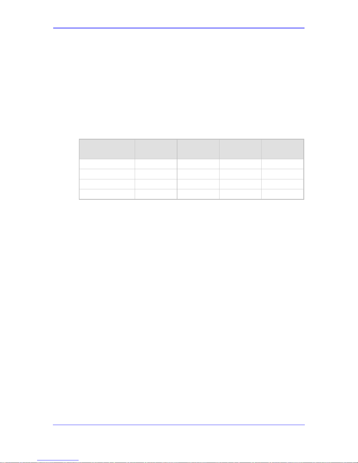
The table below compares the telephony support bet ween these MP1xx models:
Table 1-1: MP-1xx Model Telephony Support
MP-1xx Model FXS FXO
Combined
FXS + FXO
Number of
Channels
MP-112
2
MP-114
2 + 2 4
MP-118
4 + 4 8
MP-124
24

Hardware Installation Manual 8 Document #: LTRT-59815
MediaPack Series
Reader’s Notes
Version 6.6 9 April 2012
Hardware Installation Manual 2. MP-11x Hardware Installation
2 MP-11x Hardware Installation
This chapter describes the MP-11x hardware installation.
2.1 Physical Description
The subsections below provide a physical description of the front and rear panels of the
MP-11x.
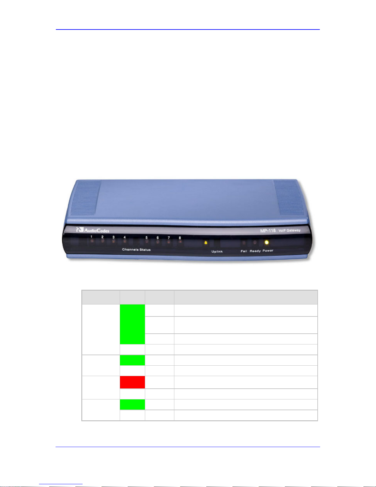
2.1.1 MP-11x Front Panel (LEDs Description)
The device's front panel provides LEDs for indicating various operating statuses. The figure
below displays the front panel of the MP-118. This is similar to the MP-114 and MP-112
models, differing only in the number of Channel Status LEDs (corresponding to the
number of channels).
Figure 2-1: MP-11x Front Panel (e.g., MP-118)
The device’s LEDs are described in the table below:
Table 2-1: MP-11x Front-Panel LEDs Description
LED Color State Definition
Channels
Status
Green
Blinking Phone is ringing (incoming call, before answering).
Fast
Blinking
Line malfunction.
On Phone is in off-hook position or ringing.
- Off Phone is in on-hook position.
Uplink
Green On Valid 10/100Base-TX Ethernet connection.
- Off No Ethernet uplink.
Fail
Red On
Failure (fatal error) or system initialization.
- Off Normal working condition.
Ready
Green On Device powered up, self-test OK.
-
Off Loading software or system failure.
Hardware Installation Manual 10 Document #: LTRT-59815
MediaPack Series
LED Color State Definition
Power Green
On Power is received by the device.
-
Off Failure / disruption in the AC power supply or power
is currently not being supplied to the device through
the AC power supply entry.
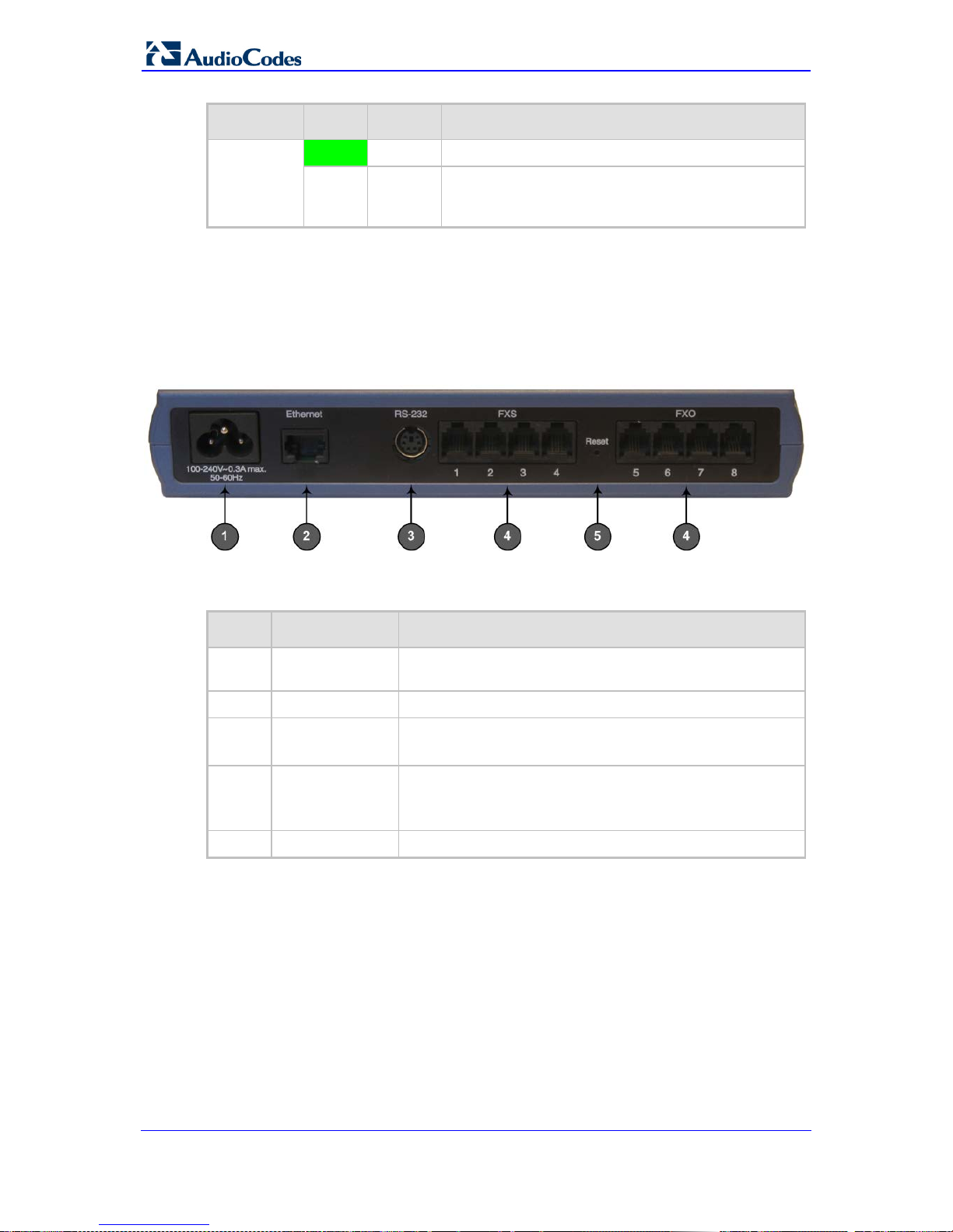
2.1.2 MP-11x Rear Panel (P orts Description )
The device's rear panel provides the ports for cabling the device to the various interfaces.
The figure below displays the rear panel of the M P-118 device (as an example).
Figure 2-2: MP-11x Rear Panel (e.g., MP-118)
The table below describes the ports on the MP-11x rear panel:
Table 2-2: MP-11x Rear Panel Component Descriptions
Item # Label Component Description
1
100-240~0.3A
max. 50-60Hz
AC power supply socket.
2
Ethernet
10/100Base-TX Uplink port.
3
RS-232
RS-232 status port (requires a DB-9 to PS/2 adaptor).
Note: MP-112 does not provide a serial port.
4 FXS and/or FXO Provides two, four, or eight FXS/FXO ports (depending on
MediaPack model).
Note: MP-112 does not support FXO interfaces.
5
Reset
Reset button for resetting the device.
2.2 Unpacking and Checking Package Contents
Follow the procedure below for unpacking the carton in which MP-11x is shipped.
To unpack MP-11x:
1. Open the carton and remove the packing materials.
2. Remove the MP-11x unit from the carton.
3. Check that there is no equipment damage.
Version 6.6 11 April 2012
Hardware Installation Manual 2. MP-11x Hardware Installation
4. Ensure that in addition to the MP-11x unit, the package contains the following items:
• AC power cable.
• Small plastic bag containing four anti-slide bump ers for desktop installation.
• Regulatory Information document.
5. Check, retain, and process any documents.
6. Notify AudioCodes or your local supplier of any damage or discrepancies.
2.3 Mounting MP-11x
The device can be mounted in one of the following ways:
Desktop mounting - see 'Desktop Mounting' on page 12
Wall mounting - see 'Wall Mounting' on page 12
Standard 19-inch rack mounting - see '19-inch Rack Mounting' on page 12
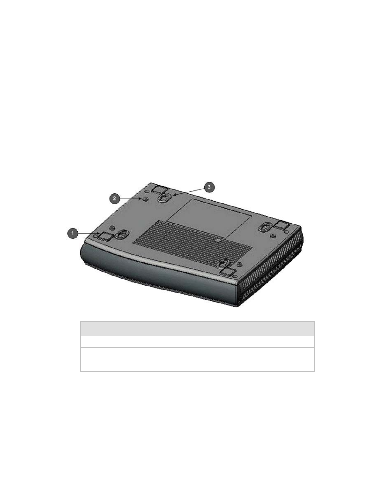
The figure below shows the mounting components on the underside of MP-11x:
Figure 2-3: MP-11x Underside
Table 2-3: Mounting Components on MP-11x Underside
Item # Description
1
Square slot used to attach anti-slide bumpers (for de sktop mounting).
2
Screw opening used to attach MP-11x to a 19-inch shelf rack.
3
Oval notch used to attach MP-11x to a wall.
 Loading...