


MP-124
Table of contents
 Loading...
MediaPack™ Series
Analog VoIP Media Gateways
MGCP & MEGACO Protocols
User's Manual
MP-1xx & MP-124
Version 6.6
June 2014
Document # LTRT-71405


User's Manual Contents
Table of Contents
1 Introduction ......................................................................................................... 9
1.1 About the MediaPack Gateway............................................................................... 9
1.2 MediaPack Features ............................................................................................. 10
1.3 Functional Block Diagrams ................................................................................... 11
2 Software Package.............................................................................................. 13
2.1 Installing the Software Package ........................................................................... 13
2.1.1 Installing/Unzipping When Using a Windows™ Operating System ........................13
2.1.2 Unzipping When Using a Linux™/Solaris™ Operating System ..............................13
2.2 Software Directory Contents & Structure .............................................................. 14
3 Getting Started .................................................................................................. 15
3.1 Assigning the MediaPack IP Address ................................................................... 15
3.2 Assigning an IP Address Using HTTP .................................................................. 16
3.3 Assigning an IP Address Using BootP .................................................................. 17
3.4 Restoring Networking Parameters to their Default Values .................................... 18
4 Device Initialization & Configuration Files ...................................................... 19
4.1 Boot Firmware & Operational Firmware ................................................................ 19
4.2 MediaPack Startup ............................................................................................... 19
4.3 Using BootP/DHCP .............................................................................................. 21
4.3.1 BootP/D HCP Ser ver Para meters ............................................................................21
4.3.1.1 Command Line Switches..........................................................................22
4.3.2 Host Name Support .................................................................................................23
4.3.3 Selecti ve BootP .......................................................................................................24
4.3.4 Microsoft™ DHCP/BootP Server .............................................................................24
4.4 Configuration Parameters and Files ..................................................................... 25
4.4.1 Initialization (ini) File ................................................................................................25
4.4.1.1 Parameter Value Structure .......................................................................26
4.4.1.2 Tables of Parameter Value Structure .......................................................27
4.4.1.3 Binary Configuration File Download .........................................................30
4.4.2 Auxiliary Files ...........................................................................................................30
4.4.2.1 Downloading Auxiliary Files via TFTP During the Blade Startup .............30
4.4.2.2 Automatic Update Facility.........................................................................31
4.4.2.3 Downloading the dat File to a Device .......................................................34
4.5 Backup Copies of ini and Auxiliary Files ............................................................... 35
4.6 Upgrading Device Software .................................................................................. 35
5 Automatic Configuration Options .................................................................... 37
5.1 Option A - Local Configuration Server with BootP/TFTP ....................................... 37
5.2 Option B - DHCP-based Configuration Server ...................................................... 38
5.3 Option C - HTTP-based Automatic Updates ......................................................... 39
5.4 Option D - Configuration using DHCP Option 67 .................................................. 40
5.5 Option E - Configuration using FTP or NFS .......................................................... 41
5.6 Option F - TFTP Configuration using DHCP Option 66 ........................................ 41
5.7 Option G - Configuration using AudioCodes EMS ................................................ 41
6 Configuration Using the Web Interface ........................................................... 43
6.1 Limiting the Web Interface to Read-Only Mode .................................................... 43
Version 6.6 3 MediaPack Series

6.1.1 Encrypted HTTP Transport (HTTPS - SSL) ............................................................44
6.1.2 Limiting Web Access to a Predefined List of Client IP Addresses ..........................44
6.1.3 Managing Web Server Access Using a RADIUS Server .........................................44
MediaPack Series
6.2 Accessing the Web Interface ................................................................................ 45
6.3 Using Internet Explorer to Access the Web Inter f ace ............................................ 46
6.4 Areas of the GUI ................................................................................................... 47
6.4.1 Toolbar .....................................................................................................................48
6.4.2 Navigation Tree .......................................................................................................49
6.4.2.1 Displaying Navigation Tree in Basic and Full View ..................................49
6.4.2.2 Showing / Hiding the Navigation Pane .....................................................50
6.4.3 Help Infrastructure ...................................................................................................51
6.4.4 Working with Configuration Pages ..........................................................................52
6.4.4.1 Accessing Pages ......................................................................................52
6.4.4.2 Viewing Parameters .................................................................................52
6.4.4.3 Displaying Basic and Advanced Parameters ...........................................53
6.4.4.4 Showing / Hiding Parameter Groups ........................................................54
6.4.4.5 Modifying Parameter Values ....................................................................54
6.4.5 Saving Configuration Changes ................................................................................55
6.4.6 Searching for Configuration Parameters .................................................................55
6.4.7 Creating a Login Welcome Message .......................................................................56
6.4.8 Logging Off the Web Interface .................................................................................57
6.4.9 Getting Help .............................................................................................................58
6.4.10 Using the Home Page ..............................................................................................59
6.4.11 MediaPack Home Page ...........................................................................................60
6.4.12 Viewing the Active Alarms Table .............................................................................61
6.4.13 Viewing Channel Information ...................................................................................62
6.4.14 Viewing Ethernet Port Information ...........................................................................63
6.4.15 Viewing Ethernet Port Information ...........................................................................63
6.4.16 Viewing Trunk Settings ............................................................................................64
6.4.17 Assigning a Name or Brief Description to a Port .....................................................64
6.4.18 Resetting an Analog Channel ..................................................................................65
6.5 Configuration ........................................................................................................ 66
6.5.1 System .....................................................................................................................66
6.5.1.1 Application Settings ..................................................................................66
6.5.1.2 Syslog Settings .........................................................................................68
6.5.1.3 Regional Settings .....................................................................................68
6.5.1.4 TLS Contexts ............................................................................................69
6.5.1.5 Management ............................................................................................75
6.5.2 VoIP .........................................................................................................................88
6.5.2.1 Network ....................................................................................................88
6.5.2.2 IP Interface Table .....................................................................................88
6.5.2.3 Static Route Table ....................................................................................89
6.5.2.4 Network Settings ......................................................................................90
6.5.2.5 QoS Settings ............................................................................................91
6.5.2.6 Security Settings ......................................................................................92
6.5.2.7 Media ......................................................................................................100
6.5.2.8 Quality of Experience .............................................................................115
6.5.2.9 Call Control .............................................................................................116
6.6 Maintenance ....................................................................................................... 122
6.6.1 Maintenance ..........................................................................................................122
6.6.1.1 Maintenance Actions ..............................................................................122
6.6.2 Software Update ....................................................................................................126
6.6.2.1 Load Auxiliary Files ................................................................................126
6.6.2.2 Software Upgrade Key ...........................................................................127
6.6.2.1 Software Upgrade Wizard ......................................................................130
6.6.2.2 Configuration File ...................................................................................136
6.7 Status and Diagnostic Menu ............................................................................... 139
User's Manual 4 Document #: LTRT-71405

User's Manual Contents
6.7.1 System Status ........................................................................................................139
6.7.1.1 Message Log ..........................................................................................139
6.7.1.2 Device Information .................................................................................140
6.7.1.3 Ethernet Port Information .......................................................................141
6.7.1.4 Carrier-Grade Alarms .............................................................................141
6.7.2 VoIP Status ............................................................................................................143
6.7.2.1 Active IP Interfaces ................................................................................143
6.7.2.2 Performance Statistics ...........................................................................144
7 Troubleshooting .............................................................................................. 145
7.1 Troubleshooting MediaPack Devices via the RS-232 Port .................................. 145
7.1.1 Viewing the Gateway's Information .......................................................................145
7.1.2 Changing the Networking Parameters ...................................................................146
7.1.3 Determ ining Me dia Pack Initialization Problem s ....................................................146
7.1.4 Reinitializing the MediaPack ..................................................................................147
7.2 LED Indicators .................................................................................................... 149
7.2.1 MediaPack Front View LED Indicators ..................................................................149
7.3 MediaPack Self-Testing ...................................................................................... 150
7.3.1 FXS Line Testing ...................................................................................................150
7.3.2 FXO Line Testing ...................................................................................................151
7.4 Self-Test ............................................................................................................. 152
7.4.1 Operating t he Sys log Ser ve r .................................................................................153
7.4.1.1 Sending the Syslog Messages ...............................................................153
7.4.1.2 Activating the Syslog Client ....................................................................153
7.4.1.3 Setting Syslog Server IP Address, Enabling Syslog, in an ini File
(Example) ..............................................................................................................153
8 List of Abbreviations ....................................................................................... 155
9 Technical Specifications ................................................................................ 159
Version 6.6 5 MediaPack Series

MediaPack Series
Reader's Notes
User's Manual 6 Document #: LTRT-71405

User's Manual Notices
Notice
This document provides you with information on installation, conf iguration, and operation of
MP-1X8 (8-port), MP-1X4 (4-port), MP-1X2 (2-port) the MP-124 (24-port) Media G ate wa ys.
Information contained in th is document is believed to be accurate and reliab le at the time of
printing. However, due to ongoing product im provements and revisions, AudioC odes cannot
guarantee accuracy of printed material after the Date Published, nor can it accept
responsibility for err ors or omissions. Updates to this document and ot her documents as well
as software files can be viewed by registered customers at
http://www.audiocodes.com/downloads.
© Copyright 2014 AudioCodes Ltd. All rights reserved.
This document is subject to change without notice.
Date Published: June-10-2014
Trademarks
AudioCodes, AC, AudioCoded, Ardito, CTI2, CTI², CTI Squared, HD VoIP, HD VoIP
Sounds Better, InTouc h, IPmedia, Mediant, M ediaPack, NetCoder, Netrak e, Nuera, Open
Solutions Network, OSN, Stretto, TrunkPack, VMAS, VoicePacketizer, VoIPerfect,
VoIPerfectHD, W hat's Inside Matt ers, Your Gateway T o VoIP and 3GX are tradem arks or
registered trademarks of AudioCodes Limited. All other products or trademarks are
property of their r espective owners. Product specif ications are subject to chang e without
notice.
WEEE EU Directive
Pursuant to the W EEE EU Directive, elect ronic and electrical waste m ust not be disposed
of with unsorted waste. Please contact your local recycling authority for disposal of this
product.
Customer Support
Customer technical s upport and s ervices are provided by Au dioCodes or b y an authorized
AudioCodes Service Partner. For more information on how to buy technical support for
AudioCodes products and for contact information, please visit our Web site at
www.audiocodes.com/support
Documentation Feedback
AudioCodes continually strives to produce high quality documentation. If you have any
comments (suggestions or errors) regarding this document, please fill out the
Documentation Feedback form on our Web site at http://www.audiocodes.com/downloads
.
.
Version 6.6 7 MediaPack Series

MediaPack Series
Reader's Notes
User's Manual 8 Document #: LTRT-71405

User's Manual 1. Introduction
1 Introduction
This document prov ides you with inform ation on i ns tal latio n, c o nf igur at ion , a nd op er ation of
the MP-124 (24-port), MP-1X8 (8-port), MP-1X4 (4-port) and MP-1X2 (2-port) Media
Gateways. As these un its have sim ilar f unctio nalit y (ex cept for the num ber of channels and
some minor features) , they are referred to collecti vely as the MediaPack. Prior knowledge
1.1 About the MediaPack Gateway
of regular telephony and data networking concepts is preferred.
The MediaPack series analog VoIP gateways are cost-effective, cutting e dge technology
products. These st and-alone analog VoI P gateways provide sup erior voice technol ogy for
connecting legacy telephones, fax machines and PBX systems with IP-based telephony
networks, as well as for integration with new IP-based PBX architec ture. These products
are designed and tested to be fully interoperable with leading softswitches and servers.
The MediaPack gatewa ys incorporate up to 24 analog ports f or connection, either directl y
to an enterprise PBX (F XO), to phones, or t o fax (FXS), suppor ting up to 24 simultaneo us
VoIP calls.
Additionally, the MediaPack units are equipped with a 10/100 Base-TX Ethernet port for
connection to the network.
The MediaPack gateways are best suited for small to medium size enterprises, branch
offices or for residential media gateway solutions.
The MediaPack gatewa ys enable users to make free local or international telephone / fax
calls between the d istributed com pany offices, us ing their exis ting telephones / fax. Thes e
calls are routed over the existing network ensuring that voice traffic uses minimum
bandwidth.
The MediaPack gatewa ys are compact devices t hat can be installed as a desk-top unit or
on the wall or in a 19-inch rack.
Version 6.6 9 MediaPack Series

MediaPack Series
1.2 MediaPack Features
The followin g provides a high-level overview of some of the many MediaPack supported
features.
Superior, high quality Voice, Data and Fax over IP networks.
Toll quality voice compression.
Vocoder configuration options include:
• G.711 A/u-law PCM, G.726 ADPCM, G.727 ADPCM, G.723.1, G.729 A B,
EG.711, G.722 (in Analog modules)
Enhanced capabilities including MWI, long haul, metering, CID and outdoor protection.
Proven integration with leading PBXs, IP-PBXs, Softswitches and servers.
Spans a range of 2 to 24 FXS/FXO analog ports.
Selectable G.711 or multiple Low Bit Rate (LBR) coders per channel.
T.38 fax with superior performance (handling a round-trip delay of up to nine
seconds).
Echo Canceler, Jitter Buffer, Voice Activity Detection (VAD) and Comfort Noise
Generation (CNG) support.
Comprehensive support for supplementary services.
Web Management for easy configuration and installation.
EMS for comprehensive management operations (FCAPS).
Simple Network Management Protocol (SNMP) and Syslog support.
SMDI support for Voice Mail applications.
Multiplexes RTP streams from several users together to reduce bandwidth overhead.
T.38 fax fallback to PCM (or NSE).
Can be integrated into a VLAN-aware environment.
Capable of automatically updating its firmware version and configuration.
Web access (HTTPS) and Telnet access using SSL / TLS.
User's Manual 10 Document #: LTRT-71405
User's Manual 1. Introduction
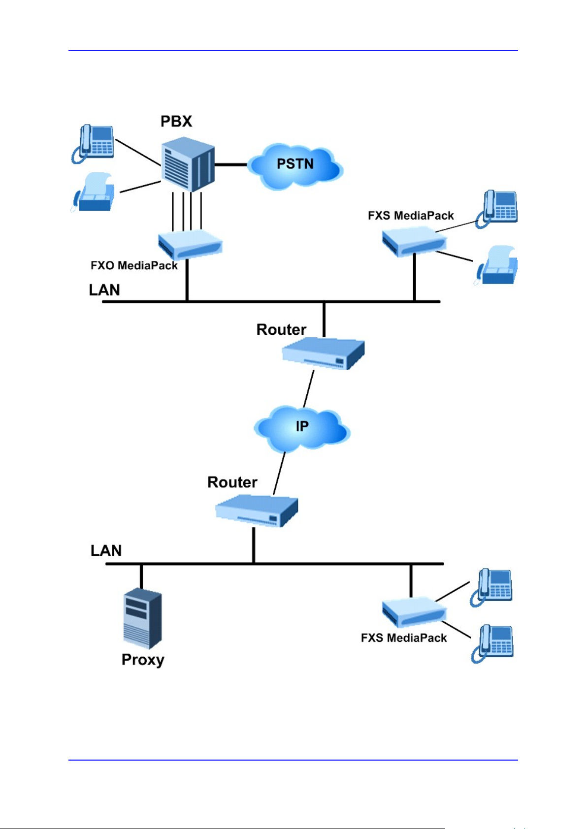
1.3 Functional Block Diagrams
Figure 1: Typical MP-11x Application Diagram
Version 6.6 11 MediaPack Series

RS-232
DTYPE-9
RJ-45
10/100
BASE-TX
PHY
CPU
DSPs
PCM
Highway
CODECs SLICs
DTYPE-
50
PCM
Highway
Host Port
PBX
RJ-45
10/100
BASE-TX
PHY
CPU
CODECs
DSPs
DAAs
RJ-11
RS-232
PS2
(debug)
PCM
Highway
Host Port
PBX
RJ-45
10/100
BASE-TX
PHY
CPU
CODECs
DSPs
DAAs
RJ-11
RS-232
PS2
(debug)
RJ-45
10/100
BASE-TX
PHY
CPU
RS-232
PS2
(debug)
DSPs
PBX
CODECs
DAAs
RJ-11
PCM
Highway
CODECs
SLICs
RJ-11
O S u ct o a oc ag a
MediaPack Series
Figure 2: MP-124D Block Diagram
Figure 3: MP-11x FXS Block Diagram
Figure 4: MP-11x FXO+FXS Functional Block Diagram
User's Manual 12 Document #: LTRT-71405

User's Manual 2. Software Package
2 Software Package
After installing and powering up the device, you are ready to install the utilities that are
included in the software package. This software package must be installed on the host
PC/machine to be us ed to manage the device. The s oftware package c an be downlo aded
by registered users from the AudioCodes Web site at www.audiocodes.com/support.
To become a registered user, follow the instructions on the Web site.
To get started:
1. To install the software package refer to Installing the Software Pack age on page 13.
2. Check the software package contents (refer to 'Software Directory Contents &
Structure' on page 14.)
2.1 Installing the Software Package
3. Perform 'Getting Started' on page 15.
The software package is available on the AudioCodes' FTP Web site.
Customers using a Windows™ operating system may choose to install the package
via the installation wizard, or choose to unzip the software package from the supplied
zip file (refer to "Installing/Unzipping When Using a Windows™ Operating System"
below).
2.1.1 Installing/Unzipping When Using a Windows™ Operating System
To install the package:
1. Double-click on the setup.exe executable file.
2. Follow on-page instructions.
To unzip when using a Windows™ Operating System:
1. Using a tool like WinZip™, open the zip file.
2. Click the ‘Extract’ button; the ‘Extract’ page opens.
3. Navigate to the directory that you require to be the r oot directory for the installation
and click the ‘Extract’ button; the files are extracted to the location you specified.
2.1.2 Unzipping When Using a Linux™/Solaris™ Operating System
To unzip when using a Linux™/Solaris™ Oper ating System:
1. To open the tar.Z archive, un-compress the tar.Z file.
2. Enter the command: tar -xvf xxxxxx.tar.
Version 6.6 13 MediaPack Series
MediaPack Series
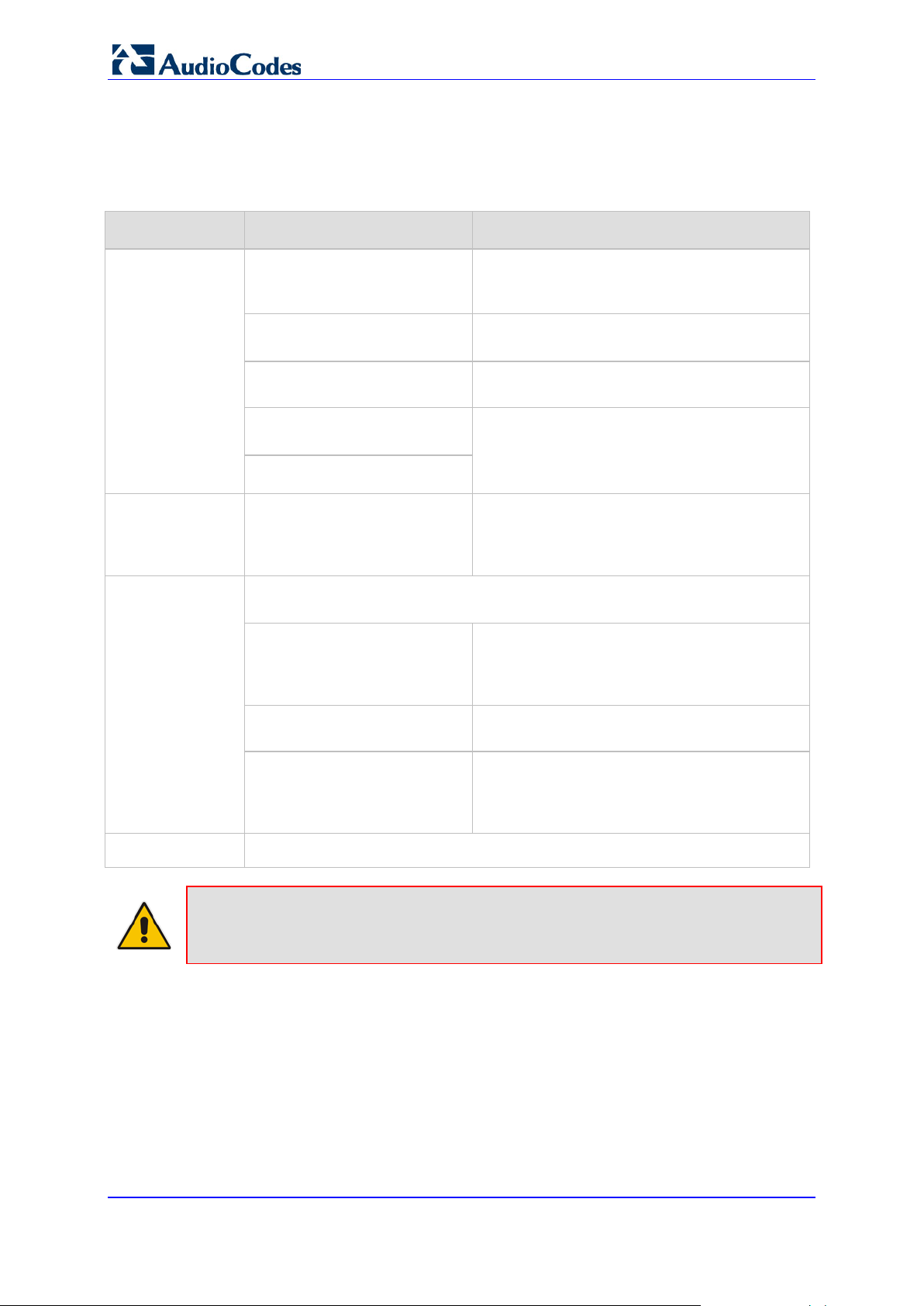
2.2 Software Directory Contents & Structure
Software Package Contents
Contents Directory Description
Auxiliary Files
Firmware
Utilities
.\Auxiliary_Files\MIB_Files
Various MIB files, e.g., SNMP MIB files:
ACL.my, RTP.my, ds1.my, MIB_2.my,
V2_MIB.my.
.\Auxiliary_Files\Sample_Call_
Progress_Files
.\Auxiliary_Files\Sample_CAS
Contains examples of Call Progress Tones
configuration files.
Contains examples of CAS protocol files.
_Protocol_Files
.\Auxiliary_Files\Sample_Ini_Fi
les
.\Firmware
Contains examples of configuration (ini) files.
Users can utilize these sample files as a
baseline for creating customized configuration
files.
Contains cmp files, loaded to the device when
changing the version of the software. When
the device is supplied to customers, it is
already configured with pre -installed firmware.
AudioCodes’ utilities pro vid e you with us er-friendly interfaces that enhance
device usability and smooth your transition to the new VoIP infrastructure.
.\Utilities\DConvert
Contains the TrunkPack Downloadable
Construction Utilit y. Use the utilit y to build Call
Progress Tones, Voice Prompts, and CAS
files.
Documentation
Note: All the demo programs described above are for reference only. Flawless
operation and stability of these applications cannot be guaranteed.
.\Utilities\PSTN_TRACE_UTILI
TY
.\Utilities\WiresharkPlugins
This utility is designed to convert Wireshark log
files containing the PSTN trace to text format.
Contains the plugins for the Wireshark network
diagnostic tool. The plugin registers itself to
handle a dissection of AudioCodes' proprietary
protocol.
All relevant product documentation
User's Manual 14 Document #: LTRT-71405

User's Manual 3. Getting Started
3 Getting Started
The MediaPack is supplied with application software alr eady resident in its flash memory
(with factory default parameters). The MediaPack is also supplied with a Web interface.
For detailed inform ation on how to fully configure the gateway refer to Device Ini tialization
& Configuration Files and the Web interface chapter below.
3.1 Assigning the MediaPack IP Address
To assign an IP address to the MediaPack u se o n e of the following methods:
HTTP using a Web browser (see 'Assigning an IP Address Using HTTP' on page 16).
BootP (see 'Assigning an IP Address Using BootP' on page 17).
DHCP (see 'Using BootP/DHCP' on page 21).
Serial communication software (e.g., HyperTerminalTM) connected to the MediaPack
via the RS-232 port.
You can use the Reset button to restore the MediaPack networking parameters to their
factory default values (refer to Restoring Networking Parameters to their Initial State on
page 18).
The default device IP Addresses are shown below.
MediaPack Default IP Parameters
FXS/FXO Interfaces Default IP Address
FXS 10.1.10.10
FXO 10.1.10.11
FXS & FXO 10.1.10.10
Default Subnet Mask 255.255.0.0
Default Gateway IP Address 0.0.0.0
Version 6.6 15 MediaPack Series

use a
MediaPack Series
3.2 Assigning an IP Address Using HTTP
To assign an IP address using HTTP:
1. Connect your PC to the device. Either connec t the network interfac e on your PC to a
port on a network hub / switch (using an RJ-45 Ethernet c able), or use an Ethernet
cross-over cable to directly connect the network interface on your PC to the RJ-45
jack on the device.
2. Change your PC’s IP addr ess and subnet mask to c orrespond with the device fac tory
default IP address and subnet mask, shown in the table above. For details on
changing the IP address and subnet mask of your PC, refer to Windows™ Online Help
(Start>Help and Support).
3. Access the Web interface (ref er to the Web interface chapter in the Pr od uct R ef erenc e
Manual).
4. Click Reset and click OK in the prompt. The device ap plies the changes and rest arts.
This takes approximately 1 minute to complete. When the device has finished
restarting, the Ready and LAN LEDs on the front view are lit green.
Tip: Record and retain t he IP address and subnet m ask you assign the devic e.
Do the same when defining a new username or password. If the Web interface is
unavailable (for example, if you’ve lost your username and password),
BootP/TFTP conf iguration uti lity to acces s the de vice, “ reflash” the load and r eset the
password.
5. Disconnect your PC from the device or from the hub / switch (depending on the
connection method you used in step 1 above).
6. Reconnect the device and your PC (if necessary) to the LAN.
7. Restore your PC’s IP address & subnet mask to what they originally were. If
necessary, restart your PC and re-access the device via the Web interface with its
new assigned IP address.
User's Manual 16 Document #: LTRT-71405

User's Manual 3. Getting Started
3.3 Assigning an IP Address Using BootP
Notes:
• The BootP procedure should be performed using any standard
compatible BootP server.
Tip: You can also use BootP to load the auxiliar y files to the device (refer to
'Using BootP/DHCP' on page 29).
• For Mediant 3000 HA, in order to get the BootP reset request from the
blade, perform a double reset on the system, as described in Private IP
Address and System (Global) IP Address.
To assign an IP address using BootP:
1. Obtain and install a BootP server application on your PC.
2. Add the client configuration for the device.
3. Reset the gateway physical ly causin g it to us e Bo otP. The dev ice chan ges i ts net work
parameters to the values provided by BootP.
Version 6.6 17 MediaPack Series

MediaPack Series
3.4 Restoring Networking Parameters to their Default Values
You can use the Reset button to restore the MediaPack networking parameters to their
factory default values (described in Default Device IP Addresses) and to reset the
username and password.
Note that this process also restores the MediaPack parameters to their factory settings,
therefore you must load your previously backed-up ini file, or the default ini file (receiv ed
with the software kit) to set them to their correct values.
To restore parameters to their initial state, take these 6 steps:
1. Back up the ini file. Refer to Backup Copies of ini and Auxiliary Files on page 35.
2. Disconnect the MediaPack from the power and network cables.
3. Reconnect the power cable; the gateway is powered up. After approximately 45
seconds, the Ready LED turns to green and the Control LED blinks for about 3
seconds.
4. While the Control LED is blink ing, use a pa per c lip to pres s shor tly on th e reset b utton
(located next to the Au dioC odes logo on the f ront v iew). The gate way resets a se cond
time and is restored with factory default parameters (username: Admin, password:
Admin - both case-sensitive).
5. Reconnect the network cable.
6. Load your previously backed-up ini file, or the default ini file (received with the
software kit). To load the ini file via the Web interface, refer to 'Software Upgrade
Wizard'.
User's Manual 18 Document #: LTRT-71405

User's Manual 4. Device Initialization & Configuration Files
4 Device Initialization & Configuration Files
This section describes the Initialization Procedures and Configuration Options for the
device. It includes:
Startup Process (see below)
Configuration Parameters and Files (refer to Configuration Parameters and Files on
25)
page
4.1 Boot Firmware & Operational Firmware
BootP/DHCP (see Using B ootP /DHCP on page 21)
The MediaPack runs two distinct software programs: Boot firmware and operational
firmware.
Boot firmware - Boot firmware (also known as flash software) resides in the
MediaPack's non-volatile memory. When the MediaPack is reset, Boot software is
initialized and the operational software is loaded into the SDRAM from a TFTP server
or integral non-volatile memory. Boot software is also responsible for obtaining the
MediaPack's IP parameters and ini file name (used to obtain the MediaPack's
configuration parameters) via integral BootP or DHCP clients. The Boot firmware
version can be viewed on the Embedded Web Server’s GUI ('Embedded Web Server'
on page
43). The last step the Boot firmware performs is to jump to invoke in the
operational software.
cmp Operational firmware file - The device is supplied with a cmp file pre-installed on
its flash memory. Therefore, this file is not included on the supplied CD. However, if
you are an AudioCodes registered customer, you can obtain the latest cmp version
files (as well as documentation and other software listed in the table above) from
AudioCodes Web site at www.audiocodes.com/support (customer registration is
performed online at this Web site). If you are not a direct customer of AudioCodes,
please contact the AudioCodes' Distributor and Reseller from whom this product was
purchased.
Note: The ini, MIB and Utility files are shipped with the device in CD format
4.2 MediaPack Startup
The MediaPack's startup process begins when the MediaPack is reset. The startup
process ends when the o perational firm ware is running. T he startup process includes how
the MediaPack obtains its IP parameters, firmware and configuration files.
The MediaPack is reset when one of the following scenarios occurs:
1. The MediaPack is manually reset.
2. acOpenRemoteBoard() is called with RemoteOpenBoardOperationMode set to Full
Configuration Mode (valid for VoPLib API users only).
3. There is a device irregularity.
4. Users perform a reset in the Embedded Web Server GUI or SNMP manager.
5. The flowchart in the figure below illustrates the process that occurs in these scenarios.
Version 6.6 19 MediaPack Series
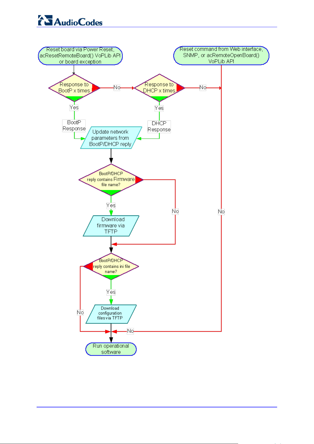
MediaPack Series
Figure 5: MediaPack Startup Process Diagram
User's Manual 20 Document #: LTRT-71405

User's Manual 4. Device Initialization & Configuration Files
4.3 Using BootP/DHCP
Notes:
• This sub-section is not applicable to Mediant 3000 HA.
• The BootP/DHCP server should be defined with an ini file name when you
need to modify configuration parameter s or when you're working with a
large Voice Prompt file that is not stored in non-volatile memory and must
be loaded after every reset.
• The default time duration between BootP/DHCP requests is set to 1
second. This can be changed by the BootPDelay ini file parameter. Also,
the default number of requests is 3 and can be changed by the
BootPRetries ini file parameter. Both parameters can also be set using the
Command Line Switches in the BootP reply packet.
• The ini file configuration parameters are stored in non-volatile memory
after the file is loaded. When a parameter is missing from the ini file, a
default value is assigned to this parameter and stored in non-volatile
memory (thereby overriding any previous value set for that parameter).
Refer to Using BootP/DHCP below.
The device uses the Bootstrap Protocol (BootP) and the Dynamic Host Configuration
Protocol (DHCP) to obtain its net working parameters and conf iguration automaticall y after
it is reset. BootP and DHC P are also used to provide the IP addr ess of a TFTP server on
the network, and files (cmp and ini) to be loaded into memory.
Both DHCP and Boot P are network protocols t hat ena ble a de vice to dis cover its ass igned
IP address; DHCP differs from BootP in that it provides a time-limited "lease" to the
assigned address. Both protocols have been extended to enable the configuration of
additional parameters specific to the device.
While BootP is always available, DHCP has to be specifically enabled in the device
configuration, before it can be used.
A BootP/DHCP request is issued after a power reset or after a device exception.
Note: BootP is normally used to initially configure the device. Thereafter, BootP is no
longer required as all parameters can be stored in the gateway’s non-volatile memory
and used when BootP is inaccessible. For example, BootP can be used again to change
the private (local) IP address of the device.
4.3.1 BootP/DHCP Server Parameters
BootP/DHCP can be used to provision the following parameters (included in the
BootP/DHCP reply. Note that some parameters are optional):
IP address, subnet mask - These mandatory parameters are sent to the device every
time a BootP/DHCP process occurs. Note that in High Availability (HA) mode, this IP
address is only private (local) and is not the HA System (global) IP address that must
be configured separately through the Interface Table.
Default gateway IP address - An optional parameter that is sent to the device only if
configured in the BootP/DHCP serv er .
Version 6.6 21 MediaPack Series

MediaPack Series
TFTP server IP address - An optional parameter that contains the address of the
TFTP server from which the firmware (cmp) and ini files are loaded.
DNS server IP address (primary and secondary) - Optional parameters that contain
the IP addresses of the primary and secondary DNS servers. These parameters are
available only in DHCP and from Boot version 1.92.
Syslog server IP address - An optional parameter that is sent to the device only if
configured in the BootP/DHCP server. This parameter is available only in DHCP.
Firmware file name – An op tional parameter that contains the name of the CMP
firmware file to be loaded to the gateway via TFTP.
ini file name - An optional parameter that contains the name of the ini file to be loaded
to the gateway via TFTP. The ini file name shall be separated from the CMP file name
using a semicolon.
Note: After programming a new cmp software image file, all configuration parameters
and tables are erased. Re-program them by downloading the ini file.
Configuration (ini) file name - The ini file is a proprietary configuration file with an ini
extension, containing configuration parameters and tables. For more information on
this file, refer to 'Configuration Parameters and Files' on page
detects that this optional parameter field is defined in BootP, it initiates a TFTP
process to load the file into the device. The new configuration contained in the ini file
can be stored in the device's integral non-volatile memory. Whenever the device is
reset and no BootP reply is sent to the blade or the ini file name is missing in the
BootP reply, the device uses the previously stored ini file.
4.3.1.1 Command Line Switches
In the BootP/TFTP Server configuration, you can add c ommand line switches in the B oot
File field. Command line s witches are used for various tasks, s uch as to determine if the
firmware should be burn ed on the non-volatile m emory or not. The table below describes
the different command line switches.
To use a command line switch:
1. In the Boot File field, leave the filename defined in the field as it is (e.g., ramxxx.cmp).
2. After "cmp", leave a space and type in the switch you require (refer to the table
below).
Example: ramxxx.cmp -fb to burn flash memory
ramxxx.cmp -fb -em 4 to burn flash memory and for Ethernet Mode 4 (auto-negotiate)
The table below lists and describes the available switches.
25. When the device
User's Manual 22 Document #: LTRT-71405

User's Manual 4. Device Initialization & Configuration Files
Command Line Switch Descriptions
Switch Description
-fb Burn ram.cmp in non-volatile memory. Only the cmp file (the compressed firmware file)
can be burned to the device's non-volatile memory.
-em# Use this switch to set Ethernet mode.
0 = 10 Base-T half-duplex
1 = 10 Base-T full-duplex
2 = 100 Base-TX half-duplex
3 = 100 Base-TX full-duplex
4 = auto-negotiate (default)
Auto-negotiate falls back to half-duplex mode when the opposite port is not in auto-
negotiate but the speed (10 Base-T or 100 Base-TX) in this mode is always configured
correctly.
-br BootP retries:
1 = 1 BootP retry, 1 sec
2 = 2 BootP retries, 3 sec
3 = 3 BootP retries, 6 sec
4 = 10 BootP retries, 30 sec
5 = 20 BootP retries, 60 sec
6 = 40 BootP retries, 120 sec
7 = 100 BootP retries, 300 sec
15 = BootP retries indefinitely
Use this switch to set the number of BootP retries that the device sends during start-up.
The device stops issuing BootP requests when either a BootP reply is received or
Number Of Retries is reached. This switch takes effect only from the next device reset.
-bd BootP delays. 1 = 1 sec (default), 2 = 10 sec, 3 = 30 sec, 4 = 60 sec, 5 = 120 sec. This
sets the delay from the device’s reset until the first BootP request is issued by the
device. The switch only takes effect from the next reset of the device.
-bs Selective BootP: The device ignores BootP replies where option 43 does not contain the
name "AUDC". Refer to Selective BootP on page 24.
-be Use -be 1 for the device to send client information back to the DHCP server. See the
“Vendor Specific Information” section below for more information.
4.3.2 Host Name Support
If DHCP is selected, the device requests a device-specif ic Host Name on the D NS server
by defining the Host Name field of the DHCP request. The host name is set to
ACL_nnnnnnn, where nnnnnnn is the serial number of the device (the serial number is
equal to the last 6 digits of the MAC address converted to decimal representation). The
DHCP server usually registers this Host Name on the DNS server. On networks which
support this setting, this feature allows us ers to configure the de vice via the web browse r
by providing the following URL: http://ACL_nnnnnnn (instead of using the device's IP
address).
Version 6.6 23 MediaPack Series

MediaPack Series
4.3.3 Selective BootP
The Selective BootP mechanism, allows the integral BootP client to filter out unsolicited
BootP replies. This c an be beneficial for environm ents where m ore than one BootP server
is available and only one BootP server is used to configure AudioCodes devices.
To activate this feature, add the command line switch -bs 1 to the Firmware File Name
field. When activated, the device accepts only BootP replies containing the text AUDC
in the Vendor Specific Information field (option 43).
To de-activate, use -bs 0.
4.3.4 Microsoft™ DHCP/BootP Server
The device can be co nfigured with an y BootP serv er, includ ing the Mic rosoft™ Windows™
DHCP server, to provide the device with an IP address and other initial parameter
configurations.
To configure the Microsof t™ Windows™ DHCP Serv er to c onf igure a n I P addr e s s to Boot P
clients, add a reservation for each BootP client.
For information on ho w to add a reservation, vie w t he "Mana gi ng Client Reservati ons He lp "
topic in the DHCP console.
The reservation builds an association between MAC address (12 digits), provided in the
accompanying devic e docu mentation) a nd the IP address . Windo ws™ Server pr ovides th e
IP address based on the device MAC address in the BootP request frame.
To configure the Microsof t™ Windows™ DHCP server to pr ovide Boot File information to
BootP clients, edit the BootP Table in the DHCP console. The BootP Table should be
enabled from the Action > Properties dialog, select the option "Show the BootP Table
Folder" and press OK. For information on editing the BootP Table, view the "Manage
BOOTP and remote access clients" Help topic in the DHCP console.
The following parameters must be specified:
Loc al IP addres s - The device’s IP address
Subnet mask
Gateway IP address - Default Gateway IP address
BootP File name - Optional (refer to the following Note)
Note: The BootP File field should normally not be used. The field is only used for
software upgrade (refer to Upgrading Device Software on page 35).
User's Manual 24 Document #: LTRT-71405

User's Manual 4. Device Initialization & Configuration Files
4.4 Configuration Parameters and Files
The device's configuration is stored in two file groups.
The Initialization file - an initialization (ini) text file containing configuration parameters
of the device.
The Auxiliary files - dat files containing the raw data used for various tasks such as
Call Progress Tones, Voice Prompts, logo image, etc.
These files contain factory-pre-configured parameter defaults when supplied with the
device and are store d i n th e de vice's non-volatile mem ory. T he de vice is s tar te d up in it ially
with this default configuration. Subsequently, these files can be modified and reloaded
using either of the following methods:
BootP/TFTP during the startup process (refer to 'Using BootP/DHCP' on page 21).
Web Interface (refer to Configuration Using the Web Interface on page 43).
Automatic Update facility (refer to Automatic Update Facility on pag e 31).
The modified auxiliar y files are burned into the n on-volatile memory s o that the modified
configuration is utilized with subsequent resets. T he configuration file is al ways stored on
the non-volatile memory. There is no need to repeatedly reload the modified files after
reset.
Notes:
• Users who configure the device with the Web interface do not require ini
files to be downloaded and have no need to utilize a TFTP server.
• SNMP users configure the device via SNMP. Therefore a very small ini file
is required which contains the IP address for the SNMP traps.
4.4.1 Initialization (ini) File
The ini file name must not include hyphens or spaces. Use underscores instead.
The ini file can contain a num ber of par ameters . The ini file st ructure s uppor ts the f ollowing
parameter value constructs:
Parameter = Value (refer to 'Parameter = Value Constructs' on page 163). The lists of
parameters are provided in the ini File Parameters chapter of the Product Reference
Version 6.6 25 MediaPack Series
Manual.
Tables of Parameter Value (refer to 'Table of Parameter Value Constructs' on page
27).
The example below shows a sample of the general structure of the ini file for both the
Parameter = Value and Tables of Parameter Value Constructs.
[Sub Section Name]
Parameter_Name = Parameter_Value
Parameter_Name = Parameter_Value
.
..
; REMARK
[Sub Section Name]

MediaPack Series
...
; Tables Format Rules:
[Table_Name]
; Fields declaration
Format Index_Name_1 ... Index_Name_N = Param_Name_1 ...
Param_Name_M
; Table's Lines (repeat for each line)
Table_Name Index_1_val ... Index_N_val = Param_Val_1 ...
Param_Val_M
[\Table_Name]
4.4.1.1 Paramet er Val ue St r uct u re
The following are the rules in the ini File structure for individual ini file parameters
(Parameter = Value):
Lines beginning with a semi-colon ';' (as the first character) are ignored.
A carriage-return/line-feed must be the final character of each line.
The number of spaces before and after "=" is not relevant.
If there is a syntax error in the parameter name, the value is ignored.
Syntax errors in the parameter value field can cause unexpected errors (because
parameters may be set to the incorrect values).
Sub-section names are optional.
String parameters, representing file names, for example,
CallProgressTonesFileName, must be placed between two inverted commas ('…').
The parameter name is NOT case sensitive; the parameter value is usually case
sensitive.
Numeric parameter values should be entered only in decimal format.
The ini file should be ended with one or more empty lines.
The example below shows a sample ini file for the MediaPack.
[MGCP]
EndpointName = 'ACgw'
CallAgentIP = 192.1.10.3
CallAgentPort = 2427
BaseUDPPort = 4000
FlashHookPeriod = 700
[Channel Params]
DJBufferMinDelay = 75
RTPRedundancyDepth = 1
User's Manual 26 Document #: LTRT-71405

User's Manual 4. Device Initialization & Configuration Files
file name extension is xxx.ini and NOT erroneously xxx.ini.ini or xxx~.ini.
[Files]
CallProgressTonesFilename = 'CPUSA.dat'
VoicePromptsFilename = 'tpdemo_723.dat'
FXSLOOPCHARACTERISTICSFILENAME = 'coeff.dat'
Note: Before loading an ini file to the device, make sure that the extension of the ini file
saved on your PC is correct: Verify that the checkbox Hide extension for known file
types (My Computer>Tools>Folder Options>View) is unchecked. Then, verify that the ini
The lists of individual ini file parameters are provided in ini File Parameters.
4.4.1.2 Tables of Parameter Value Structure
Tables group the r elated parameters of a given ent ity. Tables are compos ed of rows and
columns. The colum ns represent parameters types, while each row represent s an entity.
The parameters in e ach row are called the line attr ibutes. Rows in tables ma y represent
(for example) a trunk, SS7 Link, list of timers for a given application, etc.
Examples of the struc ture of the tables are provided below. For a list of support ed tables
please refer to the ini File Table Parameters section in the Product Reference Manual.
[ SS7_SIG_INT_ID_TABLE ]
FORMAT SS7_SIG_IF_ID_INDEX = SS7_SIG_IF_ID_VALUE,
SS7_SIG_IF_ID_NAME, SS7_SIG_IF_ID_OWNER_GROUP,
SS7_SIG_IF_ID_LAYER, SS7_SIG_IF_ID_NAI, SS7_SIG_M3UA_SPC;
SS7_SIG_INT_ID_TABLE 1 = 101, AMSTERDAM1, 3, 3, 1, 4;
SS7_SIG_INT_ID_TABLE 5 = 100, BELFAST12, 3, 3, 0, 11;
[ \SS7_SIG_INT_ID_TABLE ]
The table below is shown in document format for description purposes:
Table Structure Example
IF ID
Index
IF ID
Value
SS7_SIG_IF_ID
_NAME
SS7_SIG_IF_ID_
OWNER_GROUP
SS7_SIG_IF_ID
_LAYER
SS7_SIG_IF_
ID_NAI
SS7_SIG_
M3UA_SPC
1 101 AMSTERDAM1 3 3 1 4
5 100 BELFAST12 3 3 0 11
Version 6.6 27 MediaPack Series

MediaPack Series
4.4.1.2.1 Table Structure Rules
Tables are composed of four elements:
Table-Title - The Table's string name in square brackets. In the example above, the
Table Title is:
[ SS7_SIG_INT_ID_TABLE ].
Format Line - This line specifies the table's fields by their string names. In the example
above, the format line is: FORMAT SS7_SIG_IF_ID_INDEX =
SS7_SIG_IF_ID_VAL UE, S S7_ SIG_IF_ID_NAME,
SS7_SIG_IF_ID_OWNER_GROUP, SS7_SIG_IF_ID_LAYER, SS7_SIG_IF_ID_NAI,
SS7_SIG_M3UA_SPC
• The first word MUST be "FORMAT" (in capital letters), followed by indices field
names, and after '=' sign, all data fields names should be listed.
• Items must be separated by ',' sign.
• The Format Line must end with ';' sign.
Data Lin e( s) - The actual values for parameters are specified in each Data line. The
values are interpreted according to the format line. The first word must be the table's
string name.
• Items must be separated by a comma (',' sign).
• A Data line must end with a semicolon (';' sign).
• Indices (in both the Format line and the Data lines) must all appear in order, as
determined by the table's specific documentation. The Index field must NOT be
omitted. Each row in a table must be unique. For this reason, each table defines
one or more Index fields. The combination of the Index fields determines the 'linetag'. Each line-tag may appear only once. In the exam ple prov id ed in the tab le
above, Table Structure Example', there is only one index field. This is the
simplest way to mark rows.
• Data fields in the Format line may use a sub-set of all of the configurable fields in
a table only. In this case, all other fields are assigned with the pre-defined default
value for each configured line.
• The order of the Data fields in the Format line is not significant (unlike the Index-
fields). Field values in Data lines are interpreted according to the order specified
in the Format line.
• Specifying '$$' in the Data line causes the pre-defined default value assigned to
the field for the given line.
• The order of Data lines is insignificant.
• Data lines must match the Format line, i.e. must contain exactly the same number
of Indices and Data fields and should be in exactly the same order.
• A line in a table is identified by its table-name and its indices. Each such line may
appear only once in the ini file.
End-of-Table-Mark: Marks the end of a table. Same as Table title, but the string name
is preceded by '\'.
Below is an example of the table structure in an ini file.
; Table: Items Table.
; Fields: Item_Name, Item_Serial_Number, Item_Color, Item_weight.
; NOTE: Item_Color is not specified. It will be given default
value.
[Items_Table]
; Fields declaration
Format Item_Index = Item_Name, Item_Serial_Number, Item_weight;
User's Manual 28 Document #: LTRT-71405

User's Manual 4. Device Initialization & Configuration Files
Items_Table 0 = Computer, 678678, 6;
Items_Table 6 = Computer-page, 127979, 9;
Items_Table 2 = Computer-pad, 111111, $$;
[\Items_Table]
4.4.1.2.2 Secret Tables
A table is defined as a secret table if it contains at least one secret data field or if it
depends on such a table. A sec r et data f iel d is a f ield t hat must not be revealed to the user.
An example of a secret field can be f ound in an IPSec application. The IPsec tables are
defined as secret tables be cause the IKE ta ble c ontain s a pre-shared key field, whic h m ust
not be revealed. The SPD table depends on the IKE table. Therefore, the SPD table is
defined as a secret table.
There are two major differences between tables and secret tables:
The secret field itself cannot be viewed via SNMP, Web Server or any other tool.
ini File behavior: These t ables are never uploaded in the ini File (e.g., 'Get IN I-File from
Web'). Instead, ther e is a c omm ented title that states that the secret t able is present at the
blade, and is not to be revealed.
Secret tables are al ways kept in the blad e’s non-vola tile mem ory, and may be ov er-written
by new tables that s hould be provided in a new ini Fi le. If a secret table appears in an ini
File, it replaces the cur rent table r egardless of its cont ent. The wa y to delete a s ecret tabl e
from a blade is, for exam ple, to provide an em pty table of that t ype (with no data lines) as
part of a new ini File. The empty table replaces the previous table in the blade.
4.4.1.2.3 Tables in the Uploaded ini File
Tables are grouped according to the applications they configure.
When uploading the i ni file, the polic y is to include only tab les that belong to ap plications,
which have been configured. (Dynamic tables of other applications are empty, but static
tables are not.) The trigger for upload ing tables is further docum ented in the applications'
specific sectio ns.
4.4.1.2.4 Secret Tables
A table is defined as a secret table if it contains at least one secret data field or if it
depends on such a table. A sec r et data f iel d is a f ield t hat must not be revealed to the user.
An example of a secret field can be f ound in an IPSec application. The IPsec tables are
defined as secret tables be cause the IKE ta ble c ontain s a pre-shared key field, which m ust
not be revealed. The SPD table depends on the IKE table. Therefore, the SPD table is
defined as a secret table.
There are two major differences between tables and secret tables:
The secret field itself cannot be viewed via SNMP, Web Server or any other tool.
ini File behavior: These tables are never uploaded in the ini File (e.g., 'Get INI-File
from Web'). Instead, there is a commented title that states that the secret table is
present at the blade, and is not to be revealed.
Secret tables are al ways kept in the blad e’s non-vola tile mem ory, and may be ov er-written
by new tables that s hould be provided in a new ini Fi le. If a secret table appears in an ini
File, it replaces the cur rent table r egardless of its cont ent. The w ay to delete a sec ret table
from a blade is, for exam ple, to provide an em pty table of that t ype (with no data lines) as
part of a new ini File. The empty table replaces the previous table in the blade.
Version 6.6 29 MediaPack Series

MediaPack Series
4.4.1.3 Binary Configuration File Download
The ini file contains sens itive inform ation require d for appropr iate func tioning of the de vice.
The ini file is uplo ade d to th e de vic e or d o wnlo ade d f r om the gateway using T FTP or HTTP
protocols. These protocols are unsecured (and thus vulnerable to a potential hacker).
Conversely, if the ini file is encoded, the ini file would be significantly less vulnerable to
4.4.1.3.1 Encoding Mechanism
outside harm.
The ini file to be loaded and retrieved is available with or without encoding. When an
encoded ini file is downloaded to the device, it is retrieved as encoded f rom the device.
When a decoded file is downloaded to the device, it is retrieved as decoded from the
device.
In order to create an encod ed in i f ile, t he user must first create an ini file an d the n app l y th e
DConvert utility to it in order to encode it.
In order to decode an encoded ini file retr ieved from the device, the us er must retrieve an
encoded ini file from the device using the Web server (refer to "Downloading Auxiliary
Files" below) and then use the DConvert utility in order to decode it.
(Refer to the Utilities chap ter in the Product Refer ence Manual for detailed ins tructions on
ini file encoding and decoding.)
Downloading the in i f i le w it h or wit hout encoding ma y be per f ormed by utilizing ei ther TFTP
or HTTP.
4.4.2 Auxiliary F iles
The auxiliary files are *.dat files cont aining raw data used for a certain task such as Cal l
Progress Tones, Voice Prompts, logo image, etc. The *.dat files are created using the
DConvert utility (refer to the Utilities chapter in the Product Reference Manual), which
converts auxiliary source files into dat files. Some sample auxiliary source files are
available in the software pac kage under: .\Auxiliary_Files\.dat files. These *.dat files are
downloaded to the device using TFTP (see below) or HTTP via the Software Upgrade
Wizard (refer to Upgrading Device Software on page 35.) This section describes the
various types of auxiliary files.
Note: The auxiliary source files use the same ini file extension type as the ini
configuration file, however, the functionality is different. Whenever the term, "ini file" is
used, it refers to the configuration file and NOT to the auxiliary files.
4.4.2.1 Downloading Auxiliary Files via TFTP During the Blade Startup
Each auxiliary file has a corresponding ini file parameter in the form of
[AuxiliaryFileType]FileName. This parameter takes the name of the auxiliary file to be
downloaded to the device. I f the ini file does no t conta in a par am eter f or a specif ic auxiliar y
file type, the device uses the last auxiliary file that was stored on the non-vo l a tile memory.
The following list contains t he ini file param eters f or the diff erent types of aux iliary files t hat
can be downloaded to the device:
CoderTblFileName – The name (and path) of the file containing the coder table . This
file should be constructed using the “TrunkPack Conversion Utility” supplied as part of
the software package on the CD accompanying the device.
User's Manual 30 Document #: LTRT-71405
Loading...