

ATL Ultramark 4 Service manual

P/N 4730-0001-06 Rev C
Ultramark 4
ULTRASOUND SYSTEM
field service manual
Service Manual 4730-0001-06 Rev B consists of:
UM-4 Service Manual P/N 4720-0001-06 (9/6/94)
with the following manual changes inserted:
4725-0001-10 (9/6/94)
4725-0001-11 (4/14/95)
September, 1999

A detailed Table of Contents and List of Effective Pages begins on Page i. It includes the latest
change date for each page in the manual. Original pages will not have any date in the Contents and
List of Effective Pages or at the bottom of the page. A change bar (
) located in the outside margin
of a page denotes the specific part of a page that was changed at that date. A pointing hand (
) indicates the portion of a figure that has been revised.
Advanced Technology Laboratories, Inc.
P.O. Box 3003
Bothell, WA 98041-3003
COPYRIGHTE1992 BY ADVANCED TECHNOLOGY LABORATORIES, INC.
ALL RIGHTS RESERVED
PRINTED IN USA
“Access”, “CAD”, “Cineloop”, and “Ultramark” are registered trademarks of Advanced Technology Laboratories, Inc.
“HDI”, “Open Line Access”, and “Advanced Technology Laboratories” are trademark of Advanced Technology Laboratories, Inc.
“Matrix” is a trademark of Matrix Corporation.
“Polaroid”, “AutoFilm” and “FreezeFrame” are trademarks of Polaroid Corporation.
“Okidata” and “Microline” are registered trademarks of Oki America Inc.

Introduction
Introduction
This manual provides only information
most often needed in the field.
Experienced personnel will be able to use
accompanying performance testing, and
preventive maintenance checklists.
Organization
The manual contains major tab divisions
for diagrams, procedures, adjustments,
fault isolation, configuration supplement,
Operating Notes, Service Bulletins, reference, and parts.
ACTIVE DOCUMENT LIST: lists all active
documents pertaining to the Ultramarkr4
Ultrasound System. Listed are active service bulletins, service manuals, operation
manuals and operating notes.
OPERATING NOTES: contains operating
information not incorporated into the
operation manual.
SERVICE BULLETINS: copies of all
active service bulletins are included. “Hot
Tips” may be added as they are received
by the CSR.
REFERENCE: for information regarding
interconnecting cables and connectors
used in the Ultramarkr4, as well as other
miscellaneous information.
REPLACEABLE PARTS: illustrated parts
listings of parts commonly replaced in the
field.
REFERENCE: included are connector
pinouts, difficult removal/install instructions and other material not suited for inclusion in other manual sections.
DIAGRAMS: includes diagrams of system/
data paths, power distribution, and cabling.
PROCEDURES: contains information on
installation, performance testing, and preventive maintenance.
ADJUSTMENTS: procedures for field
authorized adjustments, including adjustment parameters and location diagrams.
FAULTISOLATION: fault isolation information in tabular format.
CONFIGURATION: hardware and software compatibility information for specific
system configurations.
Ultramark 4 Field Service Manual
Manual Usage and Update Information
The Table of Contents and List of Effective
Pages have been combined for this
manual. There is no List of Illustrations or
List of Tables. This will facilitate frequent
updating of the manual and allow TSRs to
easily determine the effective date of referenced information.
The contents of manual change packages
should be inserted as indicated on the
cover sheet attached to the package.
Changed or added pages can be identified
by the change date at the bottom of the
effected page. No change date indicates
the page is an original page. Change bars
xiii

Introduction
located in the outside margin of the page
denotes the specific part of apage that was
changed at that date. A pointing hand indicates the portion of the figure that has been
changed.
Page numbers are divided into three parts.
The prefix indicates the system. The
middle portion indicates the section within
the major tab. The suffix indicates the
actual page number.
Safety and Precautions
This section provides biological, procedural, environmental, electrical and
mechanical safety information.
WARNING statements identify conditions
or practices that could result in personal
injury or death.
CAUTION statements identify conditions
or practices that could result in equipment
damage.
Biological Safety
CAUTION:
Scanheads must be connected
and selected before turning a system on.
Do not disconnect scanheads while systems are on. Disconnect with power on
only if image has been frozen or if scanhead has been deselected.
CAUTION:
Do not sterilize scanheads with
heat, liquid, gas, or solvents. Do not autoclave or expose to temperatures exceeding 50_C (131_F). Permanent damage
may result.
WARNING:
scanheads prior to cleaning.
WARNING:
ing, and cable before using the instrument. Do
not use damaged transducers.
WARNING:
ment is classified ClassI, TypeB as defined in
IEC Standard 601-1 Safety of Medical Electrical Equipment. Electrical shock protection is
provided byconnecting theinstrument chassis
to safety ground using the 3-wire power cable
provided. This cable must be connected to a
properly grounded receptacle. Do not defeat
the grounding integrity of the equipment.
Disconnect power source and
Inspect the transducer face,hous-
Equipment grounding: This equip-
The assessment of the biological effects of
diagnostic ultrasound on humans is not
complete. Diagnostic ultrasound procedures should be used only for valid reasons, for the shortest period of time, and at
the lowest power settings necessary to
produce diagnostically acceptable
images.
Procedural Safety
WARNING:
unless another person capable of rendering
first aid is present.
xiv
Do not service or adjust a system
WARNING:
is not properly grounded. The system must be
plugged into a hospital-grade outlet.
WARNING:
power connected. Under certain conditions,
dangerous voltages may exist with power
removed. Disconnect power and discharge
circuits before touching.
WARNING:
qualified service personnel only.Avoid electric
shock and fire hazard by using proper fuses.
CAUTION:
Shock hazards exist if the system
Do not replace components with
Fusereplacement is tobedone by
Verify the system is set to
proper power source voltage and the cart
Ultramark 4 Field Service Manual
Introduction
C
C
power plug mates with the power receptacle.
WARNING:
introduced by using substituted parts or modified instruments.
WARNING:
mended by ATLmay cause electrical shock or
other unsafe conditions.
CAUTION:
Additional hazards may be
Using accessories not recom-
Verify circuit boards and components are dry before applying power to
the system.
Electro-Static Precautions
CAUTION:
This equipment contains compoents which are electro-static sensitive.
Proper static procedures, protection and
equipment must be used prior to opening,
and during handling of of this equipment.
Failure to use proper ESD procedures will
causedamagetothese components.Such
damage to components is not covered by
ATL warranties. Refer to General Field
Service Manual, (P/N 4720-0219-01) for
details.
Environmental Safety
WARNING:
presence of flammable gases or anesthetics
or in an oxygen enriched environment (i.e., in
an explosive atmosphere). An explosioncould
result.
Do not operate a system in the
can cause it to become mechanically
unstable.
CAUTION:
Do not use esters or ketone
solutions to clean parts. Discoloration (or
worse) will result.
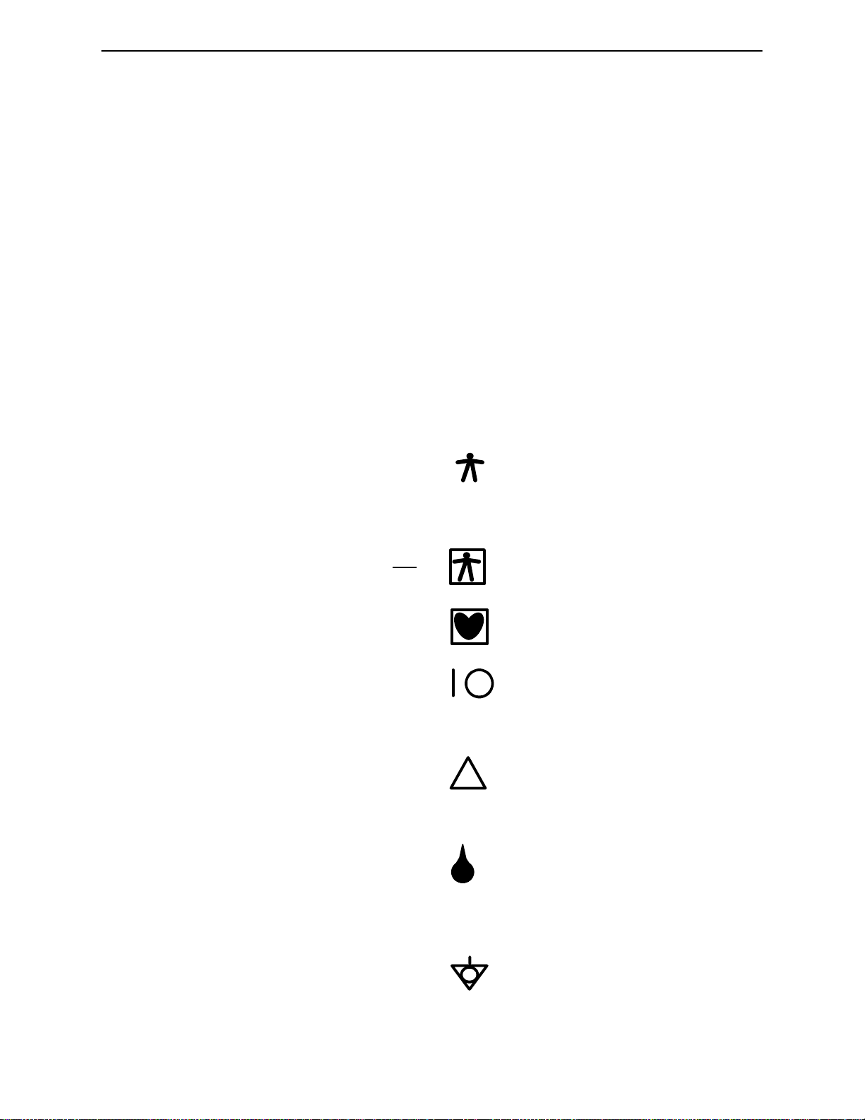
System Safety Symbology
Document IEC601-1, International Electrotechnical Commission: Safety of Medical Electrical Equipment, classifies patient
connections according to whether the
outer enclosure is grounded or floating
(non-conducting). The classifications are
shown below.
Grounded chassis. Protection
against electrical shock is provided
by connection of chassis to the
safety ground (IEC601-1 Type B).
Isolated patient connection (IE
601-1 Type BF).
Isolated patient connection (IE
601-1 Type CF).
I and O on circuit breaker and
power switch represents ON and
OFF, respectively.
This symbol identifies safety note.
!
Be sure you understand the function of this control before using it.
Drip-proof hand-held appliance
Mechanical Safety
CAUTION:
Use caution when transporting
the system over uneven surfaces, including entry to or exit from elevators.
WARNING:
equipment specified by ATL, on the system.
Ultramark 4 Field Service Manual
Stacking equipment, other than
(trans-ducer assembly). This
instrument may be safely handled
with wet hands.
Identifies protective earth ground
(located next to ground stud on the
rear panel).
xv

Introduction
The following are internal symbols (for reference only):
Identifies the point where the system safety ground is fastened to
the chassis.
Identifies high voltage components operating above 1000 Vac
or 1500 Vdc.
xvi
Ultramark 4 Field Service Manual
SCANHEADS
ACQUISITION GROUP
(A1-A4) BEAMFORMER
A1 RF Select PCB (S1)
* NO ACTIVE CIRCUITRY, JUST ROUTES SCANHEAD SIGNALS
TO FRONT END PCB (VIA CHABIN CABLES TO RF SELECT PCB
TO CENTER SECTION OF 3-PIECE MB)
A1 Doppler Pulser PCB (S2)
* VARIABLE AMPLIFIER FOR EXCITATION XMT PULSES FROM
PULSE PROCESSOR FOR MECHANICAL SCANHEADS IN CW AND
PULSED DOPPLER MODES
A2 Beamformer Front End PCB
* T/R SWITCHS BLOCK PULSERS FROM REACHING TGC
AMPLIFIERS AND BEAMFORMER FOCUS PCB
* HIGH VOLTAGE MUX SWITCHES (HV16'S). ROUTE PULSERS
TO FORM CORRECT APERTURE
* TGC AMPLIFICATION OF INCOMING RF SIGNALS
* SENDS RECEIVED RF TO BEAMFORMER FOCUS PCB
A3 Beamformer Focus PCB
* CROSSPOINT SWITCHES DEROTATE (RESTORES SEQUENCIAL
ORDER OF INDIVIDUAL CH ANNELS)
* REMOVES DELAYS FROM INDIVIDUAL INCOMING RF SIGNALS
* DEPTH OF FOCUS CONTROL
* DEMULTIPEXES (COMBINES) AND AMPLIFIES RF SIGNALS
* SENDS LINEAR RF TO PULSE PROCESSOR
A4 Beamformer Controller PCB
* DOWNLOADS OPERATING PARAMETERS (DEPTH, MODE,
S/H TYPE, ETC) FROM SYSTEM CONTROLLER TO
PROGRAMMABLE PULSE WIDTH GENERATOR
* CONTROLS BEAMFORMING
- PHASES APERTURE (CREATES PARABOLIC BEAM; OUTER
ELEMENTS FIRE FIRST; CENTER ELEMENTS FIRE LAST;
VIA MECHANICAL/ANALOG DELAY LINES)
- VARIES TRANSMIT FOCUS BY ZONE (VARIES DELAY RATIOS
OF PARABOLIC BEAM CURVE)
- SHIFTS APERTURE VIA HV MUX SWITCHES ON FRONT END
PCB (ELEM 1-32 -->2-33, ETC)
- SHIFTS DELAYS TO MAINTAIN SYMMETRY (ROTATION)
* SENDS PULSERS TO BEAMFORMER FRONT END PCB
* CONTROLS BEAMFORMER FOCUS PCB DEROTATION (REMOVING
APERTURE PHASING)
* ID'S LINEAR SCANHEADS, INCL AA
* SENDS LINEAR XDR FIRE TO PULSE PROCESSOR
Section 1A System/Data Path
A5 PULSE PROCESSOR PCB
S1
* SYSTEM RECEIVER FUNCTIONS
* OTHER FUNCTIONS SAME AS S2 PULSE PROCESSOR
S2
* GENERATES 2D XMT PULSES FOR ALL SCANHEADS
* CONTROLS POWER OUTPUT
* GENERATES TGC FOR SYS RCVR AND BMFMR FRONT
END PCB (A2)
* CONVERTS ANALOG RF INTO DIGITIZED ECHO DATA
* EDGE ENHANCEMENT/DYNAMIC RANGE
A6 DOPPLER ACQUISITION PCB
* PROCESSES CW AND PULSED DOPPLER SIGNALS FROM SYSTEM RECEIVER
TO GENERATE FORWARD AND REVERSE FLOW SIGNALS
* WALL, THUMP AND NOISE FILTERING
* A-TO-D CONVERSION
* GENERATES FORWARD AND REVERSE AUDIO SIGNALS
A7 DOPPLER PROCESSOR PCB
* GENERATES CW AND PULSED DOPPLER XMT PULSES FOR ALL SCANHEADS
* FFT OF DIGITIZED DOPPLER SIGNALS
* GRAYSCALE MAPPING
* TIMING SIGNALS FOR DOPPLER PCB'S
A8 MOTOR CONTROLLER PCB
* POSITIONAL CONTROL FOR MECHANICAL SCANHEADS
- END-FIRE (WOBBLERS)
- ACCESS (ROTARY, INCL DPLX CW) AND MERCURY
- ANNULAR ARRAY
* SENDS XDCR FIRE TO PULSE PROCESSOR PCB (A5) FOR ALL MECHANICAL S/Hs, INCL AA
* REPORTS TRANSDUCER ANGLE TO SCAN CONVERTER
* I.D.'S MECHANICAL SCANHEADS
SYSTEM RECEIVER (S2 ONLY)
* RF RELAYS; T/R SWITCHING; B.P. FILTERS, AMPS
* RCV FRONT END FOR STATIC PROBES, AND ALL MECHANICAL SCANHEADS, INCL DUPLEX CW
- XMT & RCV FRONT END FOR SECTOR 2D IMAGING (INCL DUPLEX CW; NOT AA)
- RECEIVE FRONT END FOR STATIC CW AND PULSED DOPPLER
* RF FILTERING AND NOISE SUPPRESSION
* APPLIES TGC FROM PULSE PROCESSOR TO 2D SIGNAL
* SWITCHES TO PULSE PROC FOR 2D PULSER OR TO DOP PULSE
* SWITCHES RF SIGNAL TO PULSE PROCESSOR FOR ACCESS
AND EFT 2D OR TO DOPPLER ACQUISITION FOR MECH DOP
* 7500-0511-XX SWITCHES 2D & PULSE DOPPLER BETWEEN EFT, ACCESS AND DUPLEX
CW SCANHEADS; SWITCHES CW BETWEEN STATIC PROBES AND DUPLEX CW SCANHEADS
CONTROL GROUP
(SHEET 2)
SERIAL BUS
A
C
Q
U
I
S
I
T
I
O
N
B
U
S
DISPLAY
GROUP
(SHEET 2)
ECG MODULE
* PATIENT/SYSTEM ECG ISOLATION
* ECG SIGNAL AMPLIFICATION
Ultramark 4 Field Service Manual
01 ES01-B01 01
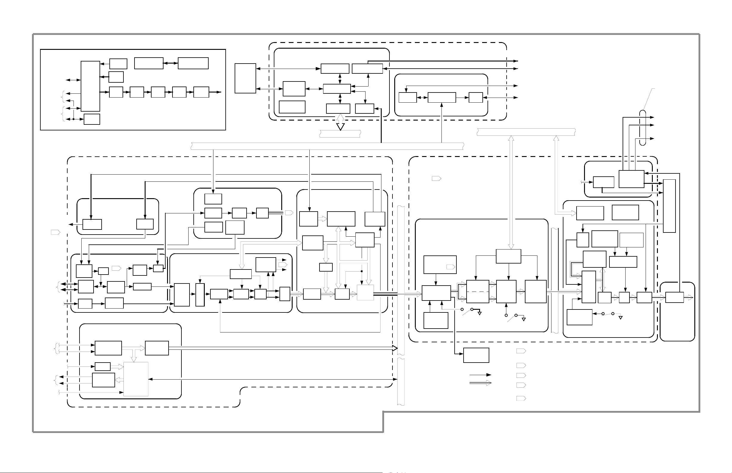
Figure 1A-1. UM-4 PCB Functions (Sheet 1 of 2)
UM4-01A-1
A15 SYSTEM CONTROLLER PCB
* RECEIVES USER COMMANDS FROM CONTROL MODULE
AND FOOTSWITCH
* CONTROLS SYSTEM PCB'S AND PERIPHERALS
* PROVIDES SYSTEM INTERFACE TO DATA COMM
MODULE OR SERIAL PORT
* CONTROLS DATA COMM DISC DRIVES
* PERFORMS ALL MEASUREMENT AND ANALYSIS
FUNCTIONS
* GENERATES REPORTS AND DRIVES PRINTER
CONTROL GROUP
KEYBOARD CONTROLLER
* PROVIDES USER INTERFACE BETWEEN CONTROL
MODULE CONTROLS AND SYSTEM CONTROLLER
1
COMBO AND CINE PCBs COMBINE FUNCTIONS OF A9
S.C. INTERFACE AND A10 S.C. BUFFER PCBs.
CINE PCB HAS EXPANDED MEMORY FOR CINELOOP.
ACQUISITION
GROUP
(Sheet 1)
A
C
Q
U
I
S
I
T
I
O
N
B
U
S
SERIAL BUS
(A9-A11) 2D SCAN CONVERTER
* FORMATS 2D ULTRASOUND DATA, EITHER POLAR
(SECTOR) OR RECTANGULAR (LINEAR) INTO
RECTANGULAR COORDINATES WITH RASTER TV
TIMING
A9 S.C. INTERFACE, COMBO OR CINE PCB
* RECEIVES CONTROL, ACQUISITION AND ADDRESS DATA
FROM BEAMFORMER, PULSE PROCESSOR, AND MOTOR
AND SYSTEM CONTROLLERS
* ACQUISITION CONTROL OF 2D AND TM-MODE SCAN
CONVERTER GROUPS VIA ACQ AND SAMPLE CLOCKS
* FRAME AVERAGING (SMOOTHING)
* INTERPOLATES SECTOR COORDINATES TO
RECTANGULAR COORDINATES (ROW AND COLUMN)
FOR DISPLAY
* MEMORY READ/WRITE CONTROL
A10 SCAN CONVERTER BUFFER PCB
* 2D SCAN CONVERSION: SHIFTS A LINE OF VIDEO IN AT
ULTRASOUND SCAN RATE (1-10 KHZ), SHIFTS OUT AT
TV HORIZONTAL SWEEP RATE (15,750 HZ, EIA; 16.625
HZ, CCIR)
* STORES 2D IMAGES FOR FREEZE FRAME AND "IMAGE
STORE" FUNCTION
A11 S. C. OUTPUT ADDRESS GENERATOR
* MANIPULATES DISPLAY ADDRESSES TO PRODUCE
PAN/ZOOM MAGNIFICATION, IMAGE BOUNDARY LIMITS ,
AND OTHER DISPLAY FEATURES
* GENERATES FRAME RATE
SERIAL BUSPARALLEL BUS
(A12-A13) TM-MODE 2D SCAN CONVERTER
* FORMATS M-MODE AND DOPPLER ULTRASOUND DATA,
INTO SCROLLING RECTANGULAR COORDINATES WITH
RASTER TV TIMING
* M-MODE AND DOPPLER SCAN CONVERSION: SHIFTS A
LINE OF DATA IN AT ULTRASOUND SCAN RATE (1-10
KHZ), SHIFTS OUT AT TV HORIZONTAL SWEEP RATE
1
(15.750 KHZ, EIA; 16.625 HZ, CC IR)
* FORMATS ECG SIGNAL ONTO DISPLAY AREA
DISPLAY GROUP
A12 TM-MODE PCB
(-OO PCB IS S1 ONLY, NO DOPPLER)
* STORES M-MODE AND DOPPLER VIDEO FOR F REEZE
FRAME
* PROCESSES AND FORMATS M-MODE, DOPPLER AND
ECG DATA
* SENDS M-MODE, DOPPLER AND ECG VIDEO TO
HARDCOPY STRIPCHART PERIPHERAL
A13 TM-AUXILIARY PCB
(REQUIRES -02 OR HIGHER TM-MODE PCB)
* GENERATES ANNOTATIONS AND MARKERS FOR
SCROLLING M-MODE AND DOPPLER DISPLAYS
A12 TM-COMBO PCB
* EQUIVALENT OF COMBINED TM-MODE AND TM-AUX
PCBS
A14 DISPLAY CONTROLLER PCB
V
I
D
E
O
B
U
S
* GENERATES ALL TV TIMING SIGNALS
* GENERATES COMPOSITE VIDEO
* GENERATES ALPHANUMBERICS AND GRAPHICS
* PROVIDES VIDEO MULTIPLEXING IN 2D/M-MODE
DISPLAY
* ACQUIRES AND STORES VIDEO FRAMES FOR DUAL
IMAGE AND IMAGE-TO-DISC FUNCTIONS
* FRAME GRABBER MEMORY FOR VCR PLAYBACK
* POST PROCESSING FOR IMAGE ENHANCEMENT
* SENDS VIDEO TO MONITOR, AND THROUGH A/V
MODULE TO AUX MONITOR AND PERIPHERALS
* SWITCHES VIDEO OUTPUT BETWEEN REAL-TIME AND
VCR PLAYBACK
VIDEO
MONITOR
AUDIO/
VIDEO
MODULE
PERIPHERALS
AND
AUXILIARY
MONITOR
UM4-01A-2
01 ES01-B02 02
Figure 1A-1. UM-4 PCB Functions (Sheet 2 of 2)
Ultramark 4 Field Service Manual
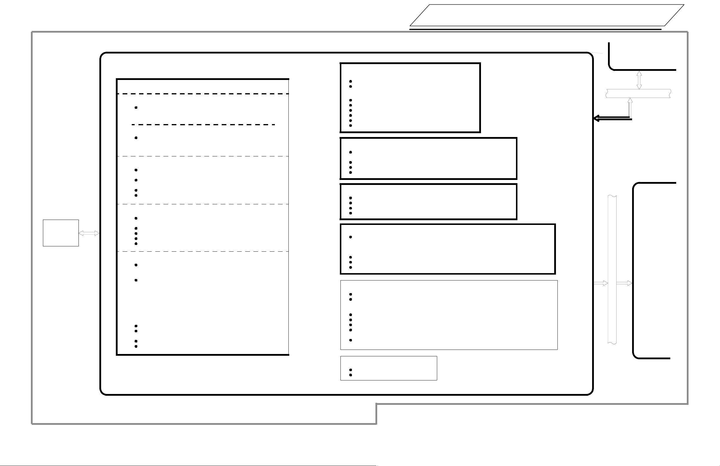
DFT
ACCESS
EFT
BEAM-
FORMER
PULSE
PROC
SYSTEM
REC
MOTOR
CONT
ACQUISITION GROUP
SYSTEM
CONTROLLER
2-D
SC
T-M
MODE
SC
KEYBOARD
CONTROLLER
DISP
CONT
VIDEO
DR
COMP
OUT
SIMPLIFIED IMAGING
DATA PATH
SERIAL BUS
DATA
COMM
MODULE
SYSTEM CONTROLLER
(A15)
FLOPPY
DISK
CONT
CLOCK
CALENDER
DATA COM M
INTERFACE
MICRO-
PROCESSOR
PARALLEL
PORTS
PARALLEL BUS
PERIPHERAL
PORTS
SERIAL
PORTS
CONTROL GROUP
KEYBOARD CONTROLLER
BUFFER
SERIAL BUS
MICRO-
PROCESSOR
UART
DISPLAY GROUP
VCR CONTRO L
HARDCOPY
DEVICES/
FOOTSWITCHES
CONTROL PANEL
ALPHANUMERIC
KEYBOARD
REAR PANEL PCB
AUX MONITOR
PHOTO MODULE
LINESCAN REC
PAGE PRINTER OR
MATRIX CAM ERA
XDR ID
DFT
ANNULAR
ARRAY
724B
ACCESS
EFT
724B
ACCESS
EFT
ANALOG
CONTROL
SIGNALS-EFT
ACCESS/724B
724B
ACCESS
EFT
XDR ID
ECG LEADS
BEAMFORMER (A1-A4)
RF
SELECT
(S1)
DOPPLER
PULSER
(S2)
(A1)
FRONT
END
(A2)
CONTROL
(A4)
TGC
(A2)
FOCUS
(A3)
A
C
Q
U
I
S
I
T
I
O
N
B
U
S
ACQUISITION
ADDRESSING
& CONTROL
FRAME
AVERAGER
MEMORY
MUX
INTERFACE
(A9)
OUTPUT
ADDRESSING
& CONTROL
BUFFER MEMORY (A10)
MEMORY
PAGE 0
MEMORY
PAGE 1
OUTPUT
ADDRESS
GENERATOR
(A11)
OUTPUT
MUX
2D SCAN
CONVERTER
INTER-
POLATOR
INTERFACE
VCR
CONTROL
(A9)
A/V
MODULE
MICRO-
PROCESSOR
A/D
VCR
DECODER
ALPHA-
NUMERIC
GENERATOR
VIDEO
TIMING
CIRCUITS
GRAPHICS
VIDEO
SPLITTER
VCR
GEN
SYSTEM RECEIVER
RF
1
RELAY
RF
RELAY
ISO
T/R
SWITCH
BUFFER
2
TGC
MOTOR CONTROLLER (A8)
POSITION
QUANTI-
TIZERS
A/D
MOTOR
DRIVERS
(3)
SERVO
CONTROL
CIRCUITS
(CPU)
LINE
COUNT/
STATUS
ECG
TGC
RF
RELAY
3
PULSER
PROC
RAMP
GEN
PULSE PROCESSOR (A5)
RF
MICRO-
PROCESSOR
A/D
MARKERS
& ANNO-
TATION
GAMMA
CORRECTION
& FILTER
ECG
PRO-
CESSING
S
E
R
I
A
L
B
U
S
4
T2
LINESCAN
RECORDER
T-M MODE SCAN CONVERTER (A12)
MEMORY
A
MEMORY
B
MUX
PARALLEL BUS
DECIMATION
AND
MUX
SCROLL
CONTROL
DATA PATH
DISPLAY
MEMORY
V
T1
SEE DOPPLER DATA PATH BLOCK DIAGRAM.
1
FOR SYSTEMS WITHOUT RESOLUTION PLUS,
2
SYSTEM RECEIVER FUNCTIONS ARE
PROVIDED BY CIRCUITRY ON THE PULSE
PROCESSOR PCB (7500-0313).
I
D
E
O
B
U
S
FRAME BUFFER
MEMORY
DIS-
PLAY
MUX
GRAY BAR
GEN-
ERATOR
OVERWRITE
MUX
POST
PROC
T1
D/A
VIDEO
RELAY
DISPLAY
CONTROLLER (A14)
FOR RESOLUTION PLUS SYSTEMS, PULSE
3
PROCESSOR PCB IS PART NUMBER 7500-0370
FOR SYSTEMS WITHOUT RESOLUTION PLUS.
PULSE PROCESSOR PCB IS 7500-0313.
MAY BE ON TM MODE PCB OR ON TM
4
AUXILLARY PCB.
VIDEO
DRIVER
MON-
ITOR
REAR
PANEL
PCB
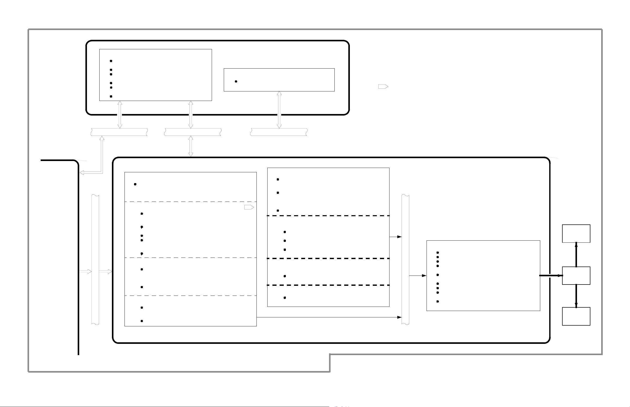
Figure 1A-2. Imaging/M-Mode Data Path Block Diagram
01 ES01-B03 01
Ultramark 4 Field Service Manual
UM4-01A-3
STATIC
XDCR
(CW)
ACCESS
EFT
SYSTEM
REC
MOTOR
CONT
DOP
PULSR
PULSE
PROC
DOP
ACQ
SYSTEM
CONTROLL ER
DOP
PROC
TM
SC
KEYBOARD
CONTROLL ER
DISP
CONT
SIMPLIFIED DOPPLER DATA PATH
VIDEO
DR
COMP
OUT
DATA
COMM
MODULE
SYSTEM CONTROLLER
DATA COMM
INTERFACE
FLOPPY
DISK
CONT
CLOCK
CALENDER
MICRO-
PROCESSOR
PARALLEL
PORTS
PARALLEL BUS
(A15)
PERIPHERAL
PORTS
SERIAL
PORTS
CONTROL GROUP
KEYBOARD CONTROLLER
BUFFER
SERIAL BUS
MICRO-
PROCESSOR
UART
VCR CONTROL
HARDCOPY
DEVICES/
FOOTSWITCHES
CONTROL PANEL
ALPHANUMERIC
KEYBOARD
PARALLEL BUS
REAR PANEL PCB
AUX MONITOR
PHOTO MODULE
LINESCAN REC
PAGE PRINTER OR
MATRIX CAMERA
STATIC
TRANSDUCER
5
ACCESS
EFT
STATIC
TRANSDUCER
ACCESS
EFT
ANALOG
CONTROL
SIGNALS-EFT
ACCESS
ACCESS
EFT
XDR ID
ACQUISITION GROUP
CW PULS
DOPPLER
PULSER (A1)
CW
BUFFER
2D PULS
SYSTEM RECEIVER
ISO
POSITION
QUANTI-
TIZERS
A/D
MOTOR
(3)
5
T/R
SWITCH
B.P.
FILTER
CONTROL
CIRCUITS
RF
RELAY
RF
RELAY
AMP
MOTOR CONTROLLER (A8)
DRIVERS
BUFFER
BUFFER
SERVO
(CPU)
PULSE
AMP
PD PULS
TGC
LINE
COUNT/
STATUS
MICRO
PROC
RF
RELAY
PULSER
DOPPLER
ACQUISITION (A6)
A
RF
RELAY
T
MIXERS
T
E
N
PULSE
PROCESSOR (A5)
RF
PROC
TGC
RAMP
GEN
CONTROL
FILT
PROC
A/D
PHASE
SHIFT &
SUMMING
GAIN
2
MUX
&
A/D
DISPLAY GROUP
4
VCR
CONTROL
A/V
MODULE
VCR
DECODER
VIDEO
SPLITTER
DOPPLER
PROCESSOR (A7)
1
SERIAL
BUS
INT
DOPPLER
ACQ
INT
FFT
INPUT
PROCESSOR
TEST
MICRO-
& MEMORY
FFT
CLOCK
ACQ
BUS
INT
CW
PULSER
INTFC
A
C
Q
U
I
S
I
T
I
O
N
B
U
S
T-M MODE
SCAN CONVERTER (A12)
MARKERS
& ANNO-
TATION
GAMMA
CORRECTION
& FILTER
CESSING
ECG
PRO-
3
MEMORY
A
MEMORY
B
T2
SCROLL
CONTROL
DECI-
MATION
AND
MUX
V
I
D
E
O
B
U
S
DISPLAY
MEMORY
T1
MICRO-
PROCESSOR
A/D
GRAY BAR
GEN-
ERATOR
FRAME
BUFFER
MEMORY
DIS-
PLAY
MUX
ALPHA-
NUMERIC
GENERATOR
POST
PROC
VIDEO
TIMING
CIRCUITS
GRAPHICS
OVERWRITE
MUX
D/A
T1
GEN
VIDEO
RELAY
DISPLAY
CONTROLLER (A14)
1
LINESCAN
S
E
R
I
A
L
B
U
S
RECORDER
DATA PATH
TO 2D SCAN CONVERTER
SEE IMAGING DATA PATH BLOCK DIAGRAM
2 SEE AUDIO DATA PATH BLOCK DIAGRAM
3 MAY BE ON TM MODE, ON TM AUXILIARY PCB, OR TM MODE COMBO PCB
4
5
ALTHOUGH NOT PART OF THE DOPPLER DATA PATH, THE
2D SCAN CONVERTER IS REQUIRED FOR DOPPLER OPERATION
REFER TO FIGURE 1A-5 FOR 3500-10 16-XX
RECEIVER AND DUPLEX CW PATH
VCR
VIDEO
DRIVER
REAR
PANEL
PCB
01 ESO1-B04 01
MONITOR
Figure 1A-3. Doppler Data Path Block Diagram
UM4-01A-4
Ultramark 4 Field Service Manual
FROM SYSTEM
CONTROLLER PCB
VCR
FROM DOPPLER
ACQUISITION PCB
2
2
2
RT/VCR
L/R PLYBK
AUDIO
L/R DOPPLER
AUDIO
A/V MODULE
AUDIO
SOURCE
SWITCH
VOLUME CONTROL
L/R AUDIO
22
AUDIO
AMPS
2
AUDIO GROUP
2
SPEAKERS
HEAD
PHONES
SYSTEM
CONTROLLER
5
VCR
CONTROL
A/V MODULE
PARALLEL
TO
SERIAL
VCR
MICROPHONE
FROM DOPPLER
ACQUISITION PCB
AUDIO
MIXER
UM-4 HFC AUDIO DATA PATH
2
VCR
AUDIO
AMPS
2
222
L/R AUDIO
VCR
DATA PATHS
SYSTEM
CONTROLLER
VCR
DISPLAY
CONTROLLER
VCR
HEAD-
PHONES
SPEAKERS
- A/V MODULE WITHOUT VCR STATUS -
A/V MODULE
VCR
7
5
CONTROL
VCR
STATUS
MICRO-
PROCESSOR
SWITCH
VIDEO
SPLITTER
CONTROL
STATUS
- A/V MODULE WITH VCR STATUS (SMART A/V) -
2
REAR PANEL
LSR
MIC
PHOTO MAP
VCR
VCR
SYSTEM
CONTROLLER
UM-4A, PV, AND CV AUDIO DATA PATH
Figure 1A-4. UM-4 Audio Data Paths and VCR Status
Ultramark 4 Field Service Manual
VCR CONTROL AND STATUS DATA PATH
01 ES01-B05 01
UM4-01A-5
UM4--01A--6
1A System/Data Path
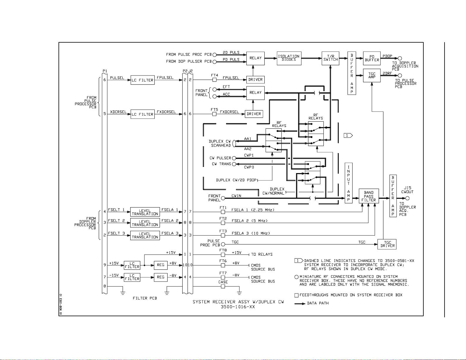
Figure 1A--5. Duplex CW System Receiver Block Diagram
Ultramark 4 Field Service Manual
1ASystem/Data Path
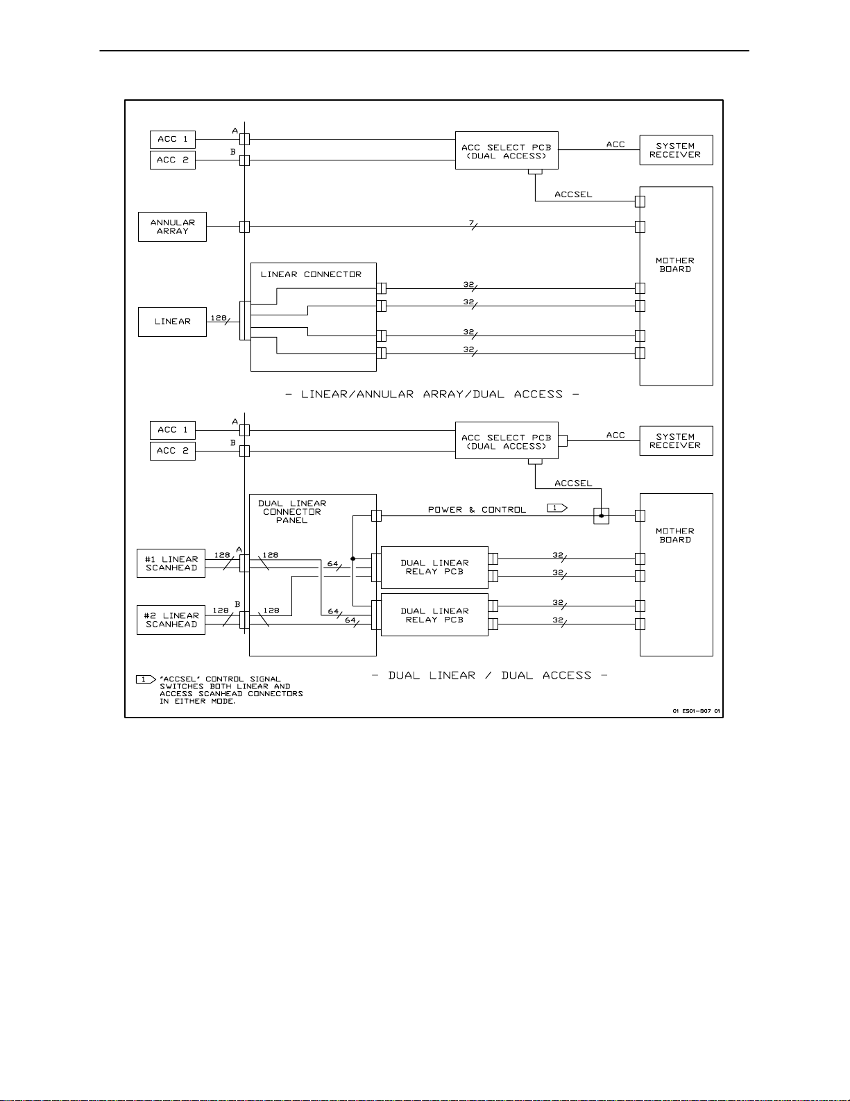
Figure 1A--6. Dual Access and Dual Linear Circuit Details
Ultramark 4 Field Service Manual
UM4--01A--7
UM4--01A--8
1A System/Data Path
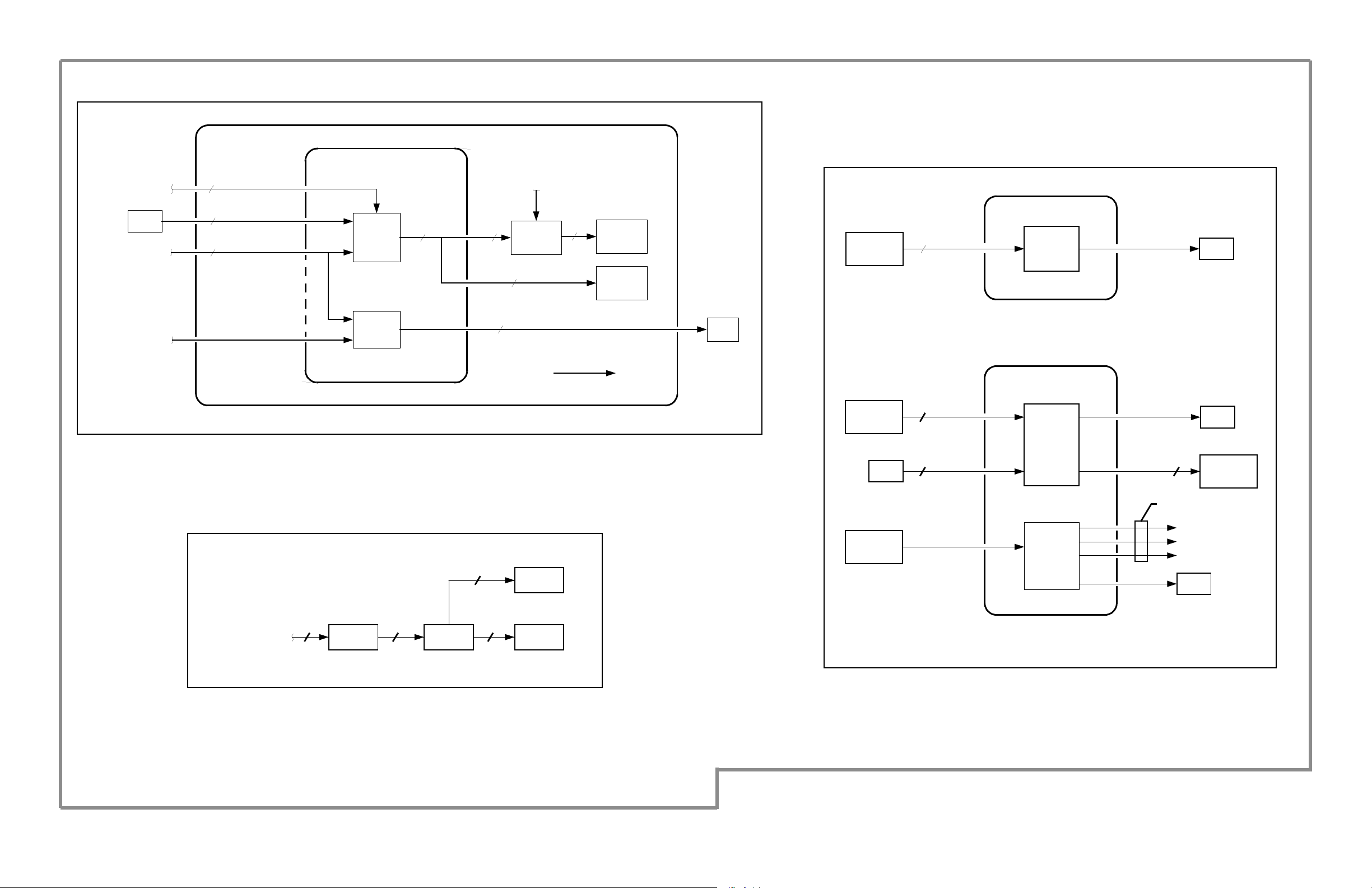
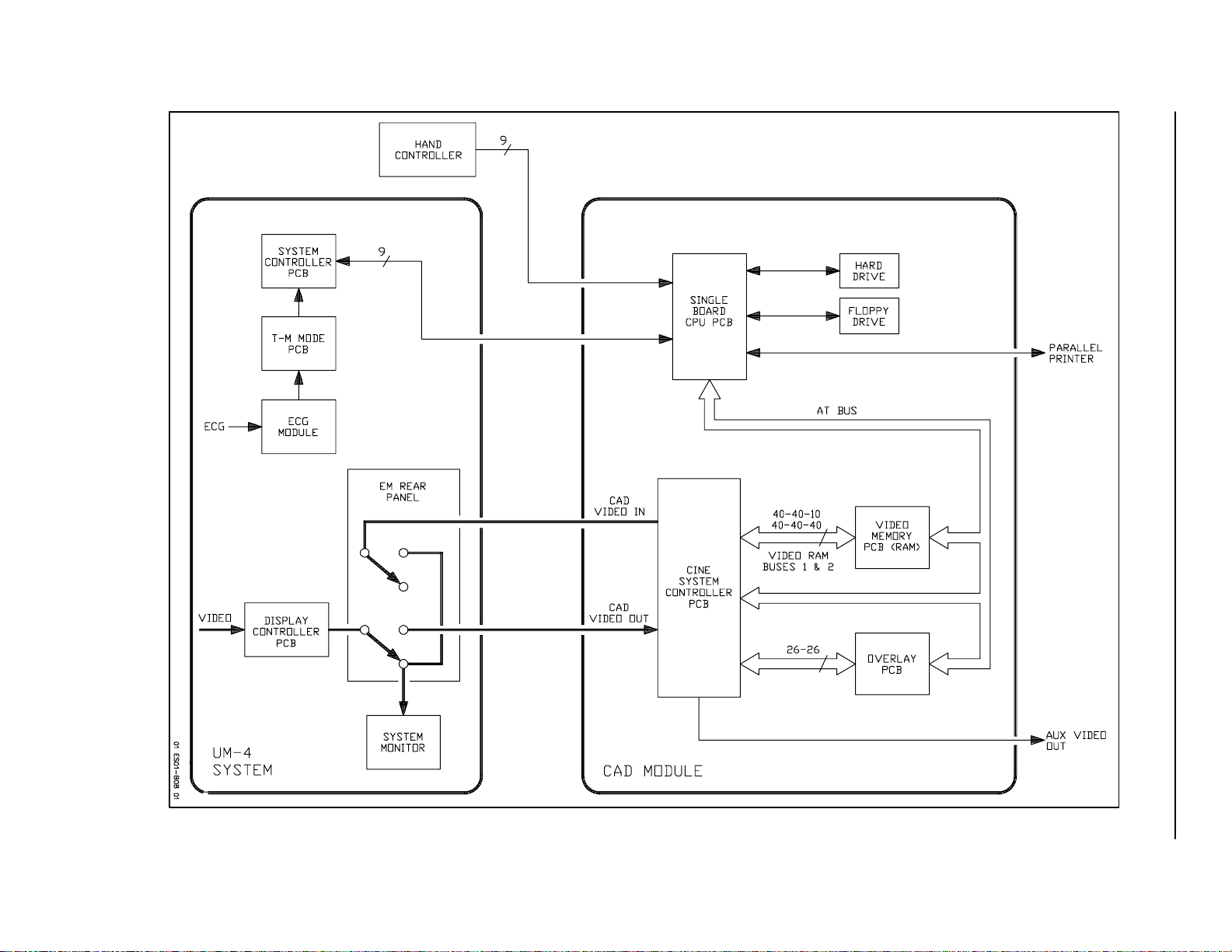
Figure 1A--7. UM-4 CAD Block Diagram
Ultramark 4 Field Service Manual
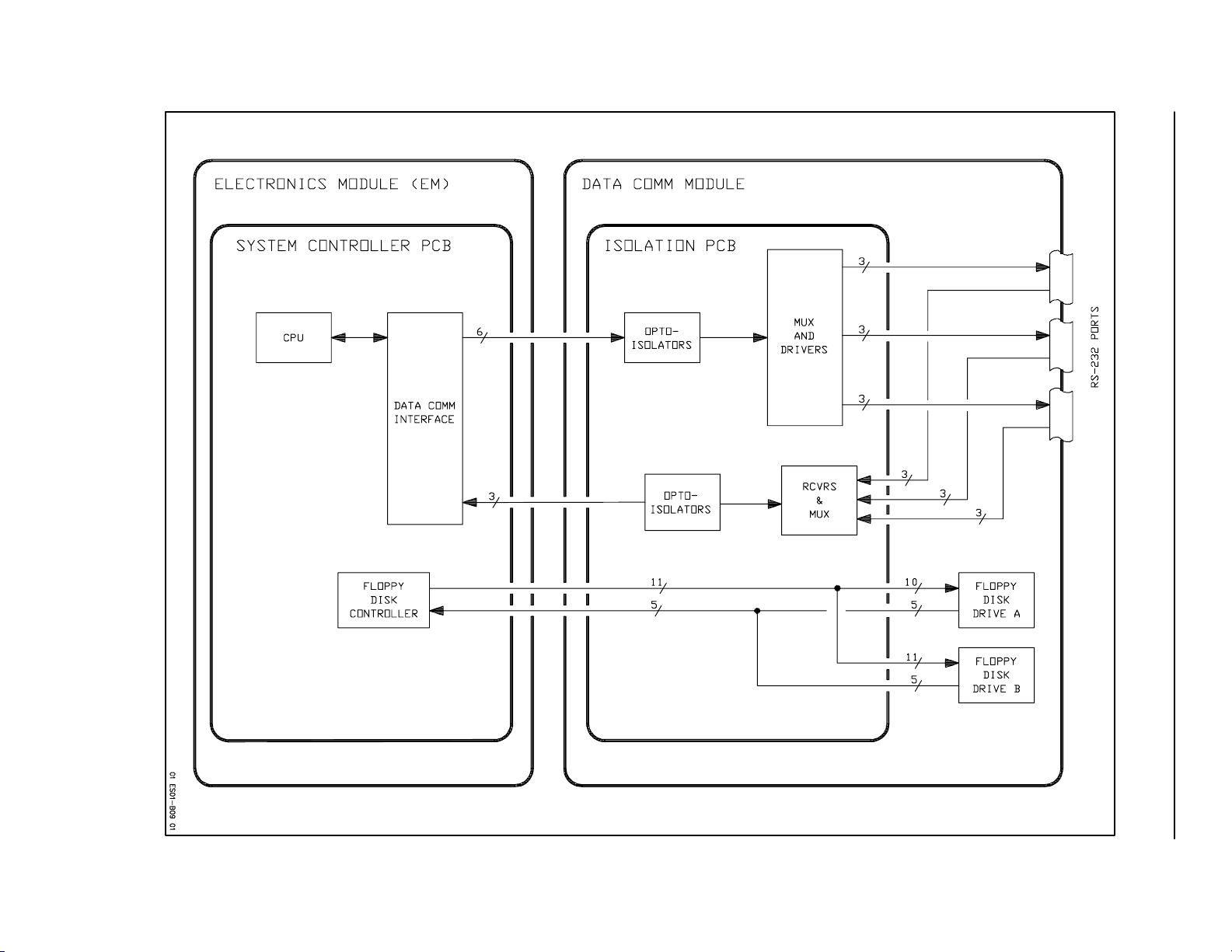
Ultramark 4 Field Service Manual
Figure 1A--8. Data Comm Block Diagram
UM4--01A--9
1ASystem/Data Path
INTERNAL
FAN
UNREGULATED +15V (MC)
Section 1B Power Distribution
J4
+9V
9V RTN
3
4
1
2
CONTROL
MODULE
AC
+15V MC
-15V MC
+5V
-5V RTN
+15V AN
-15 AN
115/230VAC
FROM POWER
DISTRIBUTION
ASSEMBLY
J1
SYSTEM
POWER SWITCH
PRIMARY PCB
LINE
CONDITIONING
AND
VOLTAGE
CONFIG.
STRAPPING
RECTIFIER
AND
FILTER
CONTROL
AND PULSE
WIDTH
MODULATOR
10V
CHANNEL
TRNSFMR
5V
CHANNEL
TRNSFMR
RECTIFIERS
AND
FILTERS
RECTIFIERS
AND
FILTERS
15V MC RTN
REGULATORS
+15V AN
-15V AN
- UM-4 -
15V AN RTN
~
F1/F2
POWER DISTRIBUTION ASSY
SYSTEM
POWER SWITCH
EM (J1)
A/V MODULE
DATA COM M
OR CAD
VIDEO PRINTER
+6V
-6V
+170V
1
1
+70V/+80V
-70V/-80V
CURRENT
SENSING
HIGH
VOLTAGE
CONTROL
6V RTN
1
1
+6V
-6V
+170V
+70V/+80V
-70V/-80V
HV RTN
J2
5
MOTOR
CONTROLLER
11
J7
(5V RAIL)
1
SYSTEM
2
PCBs
J3
1
2
10
11
5
SYSTEM
PCBs
6
3
4
9
7
8
J2
9
BEAMFORMER
PULSE PROCESSOR
8
6
PULSE PROCESSOR
7
12
BEAMFORMER
10
AC
- UM-4A -
~
BEAMFORMER
FAN MODUL E
F1/F2
POWER DISTRIBUTION ASSY
J6
BF READY
1
THERMAL SHUTDOWN
5
F3
1
+70V AND -70V USED ON S2 SYSTEMS
+80V AND -80V USED ON S1 SYSTEMS
2
T1
EM (J1)
AC
OUTLETS
2
1:1 EXCEPT FOR 35 00-1096-XX
WHICH IS 2:1 (240V IN / 120V OUT)
SHUTDOWN CONTROL LINE
HIGH TEMP
SENSE
15V AN
SECONDARY PCB
THERMAL CUTOUT
+5V
OVER-VOLTAGE
OVER-CURRENT
CONTROL
CONTROL
LOGIC
Ultramark 4 Field Service Manual
+24V
HIGH CURRENT
DETECT
24V RTN
HIGH VOLTAGE CONTROL
LOGIC COMMMON
Figure 1B-1. Power Module Block Diagram
24V RTN
+24V
POWER FAIL
RESET
+24V
2
SYSTEM MONITOR
PHOTO MODULE
1
J5
4
5
FAN MODUL E
1
2
J6
2
SYSTEM
3
PCBs
6
01 ES01-B10 01
UM4-01B-1
120/240
VAC
FPC
VCR
120/240
VAC
SCR OR
PAGE PRINTER
OR
MATRIX CAMERA
ELECTRONICS MODULE
+5 VOLTS
RETURN
SYSTEM
POWER
MODULE
1-7
8-18
AUDIO/VIDEO MODULE
P7
24
20,21
22 22
22-25 VOLT UNREG DC
+12 VOLTS
P8
18
16
2
20
3,6
1-2
9-15
P3 (D)
AC
SOCKET
A/V
MODULE
PWR
SUPPLY
+5 VOLTS
+5 VOLT
RRTN
P9
1
2-4
11
-12 VOLTS
+5 VOLTS
+5 VOLT
RETURN
12 VOLT
RETURN
D
120/240
VOLTS AC
P1
24
20,21
P2
18
16
2
20
3,6
VCR
DIGITAL
INTERFACE
VCR
STEREO
INTERFACE
1,3
2,4
1,2
14,15
P6 (I)
AUX
MONITOR
P10 (J)
AUDIO
AMPLIFIERS
P4 (H)
VCR
RETURN
1-2
9-15
E
1-2
9-15
P2 (EO1)
+24 VOLTS
+24 VOLT RETURN
1,2
9
P1 (EO2)
PHOTO
MODULE
01 ES01-B11 01
Figure 1B-2. A/V Module Power Distribution
UM4-01B-2
Ultramark 6 Field Service Manual
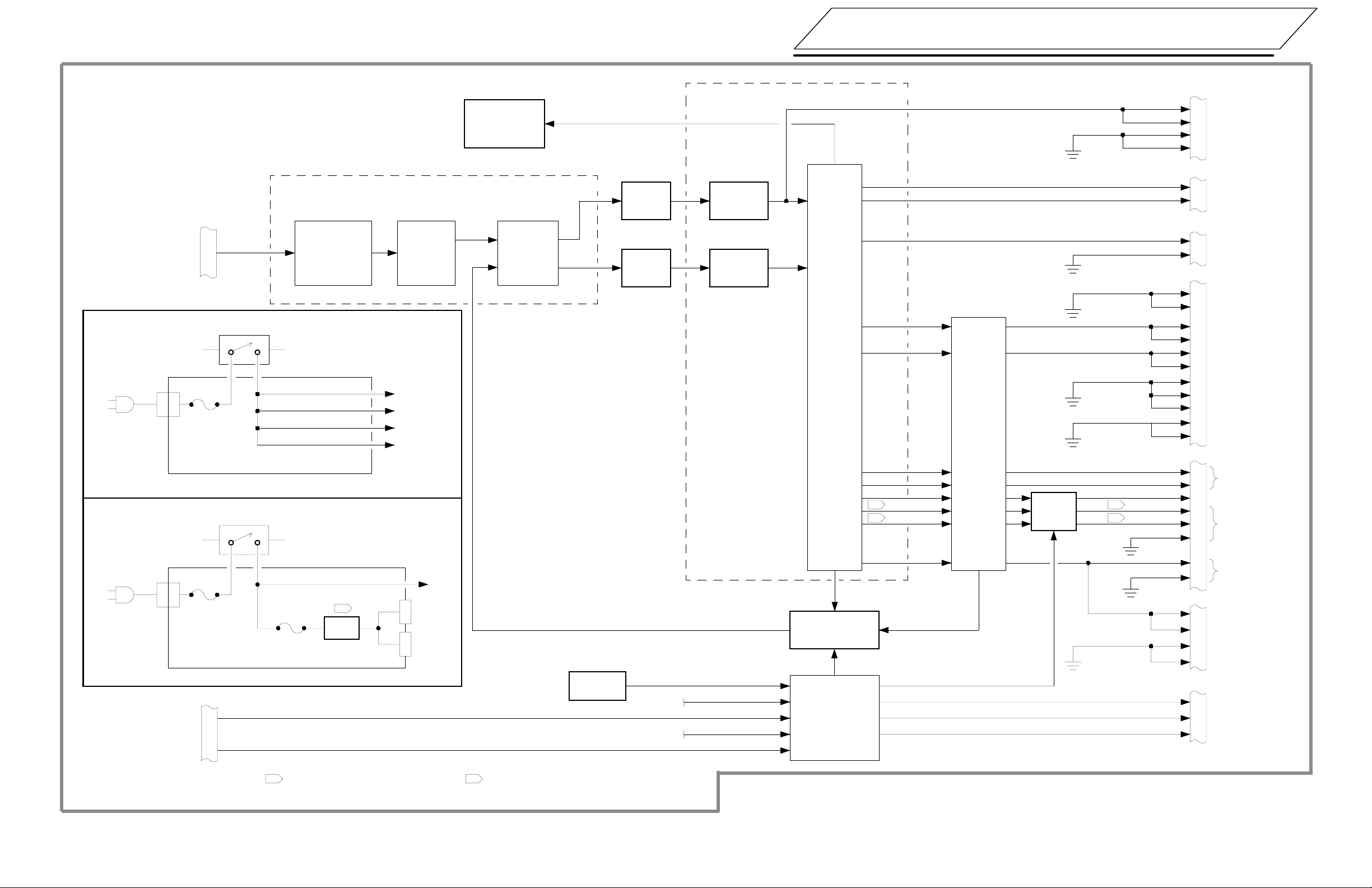
1BPower Distribution
Ultramark 4 Field Service Manual
Figure 1B--3. UM-4 Power Distribution
UM4--01B--3

1B Power Distribution
Table 1B--1. Power Distribution
POWER SUPPLY
TTL Control Signal J6-1
Power Fail
Reset
Thermal Shutdown J6-5
MOTHERBOARD
+5 Volts +5 Volt Rail
5VoltReturn
+170 Volts
+80 Volts, S1;
+70 Volts, S2
--80 Volts,S1;
--70 Volts,S2
HV Return
--15MC Volts
+15 MC Volts
15 MCV Return
+15 Volts
--15 Volts
Analog Ground
+6 Volts
--6Volts
+24 Volts
24 Volt Return
XDR Ground
SYSTEM RECEIVER
+15 Volts (analog) P1-9
- -15 Volts (analog)
Ground
DOPPLER PULSER (A1)
+5 Volts P3-4A ,4B,4C,5A,5B,5C,6A,
Digital Ground P3-1A ,1B,1C,2A,2B,2C,3A,
+15 Volts (analog)
- -15 Volts (analog)
Ground
J6-2
J6-3
5VoltReturnRail
J2-6
J2-7
J2-12
J2-10
J2-5
J2-11
J3-1,2
J3-10,11
J3-5,6
J3-3,4,7,8,9
J2-9
J2-8
J2-2
J2-1
5VoltReturnRail
P1-7
P1-8
6B,6C
3B,3C
P3-25A,25B,25C
P3-27A,27B,27C
P2-2A ,2B,4A,4B,4C,5A,6A
P3-26A,26B,26C,31A,31B,
31C
BEAMFORMER FRONT END (A2)
+80 Volts, S1; J4-1,2
+70 Volts, S2
--80 Volts,S1;
--70 Volts,S2
Return
+15 Volts
--15 Volts
Analog Ground
+6 Volts
--6Volts
BEAMFORMER FOCUS (A3)
+15 Volts
--15 Volts
Analog Ground
+6 Volts
--6Volts
BEAMFORMER CONTROLLER (A4)
Return J4-3,4
+80 Volts, S1;
+70 Volts, S2
--70 Volts,S2
TTL Control
Reset
+5 Volts
Return
+80 Volts, S1;
+70 Volts, S2
--80 Volts,S1;
--70 Volts,S2
HV Return
+15 Volts
--15 Volts
Analog Ground
J4-5,6
J4-3,4,7,8,10,12,14,16,18
J3-25A,25B,25C
J3-27A,27B,27C
J3-26A,26B,26C,32B
J3-32A
J3--32C
J3-25A,25B,25C
J3-27A,27B,27C
J1-8A,8B,8C,9A,9B,9C,10A,
J4-5,6
J4-1,2--80 Volts,S1;
J2-3C
J3-18B
J3-4A,4B,4C,5A,5B,5C,6A,
6B,6C
J3--1A,1B,1C,2A,2B,2C,3A,
3B,3C,7B,8B,9B,10B,11B,
19A,19B,19C
J3-23C
J3-23B
J3-24A,24B,24C
J3--25A,25B,25C
J3-27A,27B,27C
J3-26A,26B,26C
10B,10C,12A,12B,12C,
13C,14A,14B,14C,16A,
16B,17B,17C,23A,23B,
23C,24B,25B,25C,26B,
26C,28A,28B,28C
J3-32A
J3-32C
UM4--01B--4
Ultramark 4 Field Service Manual

Table 1B--1. Power Distribution (Cont’d)
1BPower Distribution
PULSE PROCESSOR (A5)
Reset
+5 Volts
Return
+170 Volts
HV Return
+15 Volts
--15 Volts
+6 Volts
--6Volts
DOPPLER ACQUISITION (A6)
+5 Volts
Digital Ground
+15 Volts (analog)
- -15 Volts (analog)
DOPPLER PROCESSOR (A7)
+5 Volts
Digital Ground
+6 Volts
--6Volts
J3-18B
J3-4A,4B,4C,5A,5B,6A,
6B,6C
J3-1A,1B,1C,2A,2B,2C,
3A,3B,3C
J3-23A
J3-24A,24B,24C
J3-25A,25B,25C
J3--27A,27B,27C
J2-9-20A,9-27B,9-30CAnalog Ground
J3-26A,26B,26C,31A,31B,
31C
J3-32A
J3-32C
P3-4A ,4B,4C,5A,5B,5C,
6A,6B,6C
P3-1A ,1B,1C,2A,2B,2C,
3A,3B,3C
P3-25A,25B,25C
P3-27A,27B,27C
P3-26A,26b,26C,31A,31B,Ground
31C
P3-4A ,4B,4C,5A,5B,5C,
6A,6B,6C
P3-1A ,1B,1C,2A,2B,2C,
3A,3B,3C
P3-32A
P3-32C
P2-2A ,2B,4A,4B,4C,5A,Analog Ground
6A
P3-26A,26B,26C,31A,31B,
31C
ECG ISOLATION
+15 Volts J2-9
--15 Volts
Analog Ground
SCAN CONVERTER INTERFACE (A9)
+5 Volts J3-4A,4B,4C,5A,5B,5C,
Digital Ground J1-1A,4A,6B,6C,7A,
SCANCONVERTERBUFFER(A10)
+5 Volts J3-4A,4B,4C,5A,5B,5C,
Digital Ground
J2-7
J2-1,2,3,4,6,8,10
6A,6B,6C
10A,13A,15C,16A,
19A,21B,23C,28B,
29B,30B,31B,32B
J2-3B,6B,8B,9A,9C,
12B,15B,16A,16C
17B,18B,19A,19C,
22B,26B,27A,27C
31B,32B,32C
6A,6B,6C
J1-1A,4A,6B,6C,7A,10A,
13A,15C,16A,19A,21B,
23C,28B,29B,30B,31B,
32B
J2-3B,6B,8B,9A ,9C,12B,
15B,16A,16C,17B,18B,
19B,19C,22B,26B,27A,
27C,31B,32A,32C
J3-1A,1B,1C,2A,2B,2C,
3A,3B,3C,7B,8B,9B,
10B,11B,14B,19A,19B
19C
MOTOR CONTROLLER (A8)
Power Fail J3-16A
Reset
10.00 Volts
+5 Volts
Return
--15 VoltMotor
Control J3-20A,20B,20C
+15 volt Motor
Control J3-22A,22B,22C
Return J3-21A,21B,21C
Ultramark 4 Field Service Manual
J3-18B
J1-29A
J3-4A,4B,4C,5A,5B,5C,
6A,6B,6C,16A,16B,16C
J3-1A,1B,1C,2A,2B,2C,
3A,3B,7B,8B,9B,10B,
11B,14B,15A,15B,15C,
19A,19B,19C,21C
SCAN CONVERTER OUTPUT ADDRESS GEN. (A11)
+5 Volts J3-4A,4B,4C,5A,5B,5C,6A,
6B,6C
Return J1-1A,4A,6B,6C,7A,10A,13A,
15C,16A,19A,21B,23C,
28B,29B,30B,31B,32B
J2-3B,6B,8B,9A ,9C,12B,15B,
16A,16C,17B,18B,19A,
19C,22B,26B,27A,27C,
31B,32A,32C
J3-1A,1B,1C,2A,2B,2C,3A,
3B,3C
UM4--01B--5

1B Power Distribution
Table 1B--1. Power Distribution (Cont’d)
TM-MODE (A12)
+5 Volts J3-4A,4B,4C,5A,5B,5C,6A,
Return
+15 Volts J3-25A,25B,25C
--15 Volts
Analog Ground
Reset
+15 Volts
--15 Volts
Analog Ground P4-1,2,6,8,10
TM AUXILIARY (A13)
+5 Volts P3-4A ,4B,4C,5A,5B,5C,6A,
Digital Ground
DISPLAY CONTROLLER (A14)
+5 Volts J3-4A,4B,4C,5A,5B,5C,6A,
Return
+15 Volts
--15 Volts
Analog Ground
SYSTEM CONTROLLER (A15)
+5 Volts J3-4A,4B,4C,5A,5B,5C,6A
Return J1-10A,10B,13A,13B,21A,
4.8V Battery
Reset
Power Fail
6B,6C
J2-3B,9A,9C,19A,19C,26B,
27A,27C,32A,32C
J3-1A,1B,1C,2A,2B,2C,3A,
3B,3C
J3-27A,27B,27C
J3-26A,26B,26B
J3--18B
P4-9
P4-7
6B,6C
P3-1A ,1B,1C,2A,2B,2C,3A,
3B,3C
6B,6C
J3-1A,1B,1C,2A,2B,2C,3A,
3B,3C
J3-25A,25B,25C
J3-27A,27B,27C
J1-30A,30B,30C,31A,31B
32A,32B
J3-26A,26B,26C
6B,6C
21B,21C,23A,24B,24C,
25A,25C,26A,27A,30A,
31B
J2-19A,19C,22B
J3-15B
J3-18B
J3-16A
FAN MODULE
+24 Volts P1-1,2
Return
LINESCAN RECORDER, PAGE PRINTER, VGR
+5 Volts J4(C)-12
Return J4(C)-14-23,25
+24 Volts J1(A)-1,3
Return J1(A)-2,5
+24 Volts
Return
+5 Volts
Return
+10 Volts J2(B)-1
Return
REAR PANEL (7500-0318-01, -02)
+5 Volts P1-21,23
Return
+24 Volts
Return
+10 Volts
Return
REAR PANEL (7500-0318-03, above)
+5 Volts P3-21,22
+15 Volts
--15 Volts
+24 Volts
Return
+10 Volts
Return P4-3,4
P1-4,5
SYSTEM MONITOR
PHOTO MODULE
J3(E)-1,2
J3(E)-9-15
DATA COMM MODULE
J6(F)-34
J6(F)-20,23,28,30,35-37
CONTROL MODULE
J2(B)-8,9
P2-9,11
P1-1,3
P1-9,11
P4-1,2
P4-3,4
P3-32,33
P3-27,28
P3-1,3
P3-9,11
P4-1,2
UM4--01B--6
Ultramark 4 Field Service Manual

1BPower Distribution
Table 1B--2. Power Module Connections
Power Mother- Rear Panel
Supply board PCB Other
J2 P1
J3 P2
J4 P4
J4 P2
J5 P3
J6 P1
J7 Footswitch cable
J8 *
J9 J8
*Hardwired in U318-01, -02
Table 1B--3. Power Supply Fuses
Power Supply ATL Part
Part Number Fuse Value Number
1700-0009-02
1700-0002-04,
-09, -11 F201, F202 15A,125V 2700-0072
1700-0009-01
1700-0002-05,
06, -10, -12 F201, F202 8A,250V 2700-0045
1700-0009-01
1700-0002-01 F300 2.5A N/A
Ultramark 4 Field Service Manual
UM4--01B--7
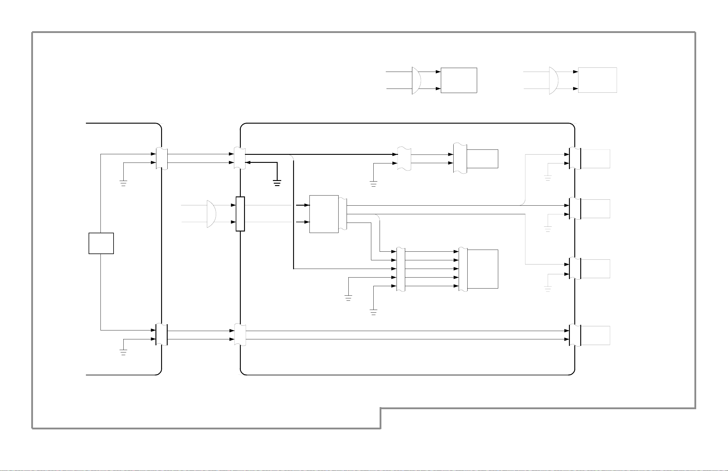
Section 1C Cabling
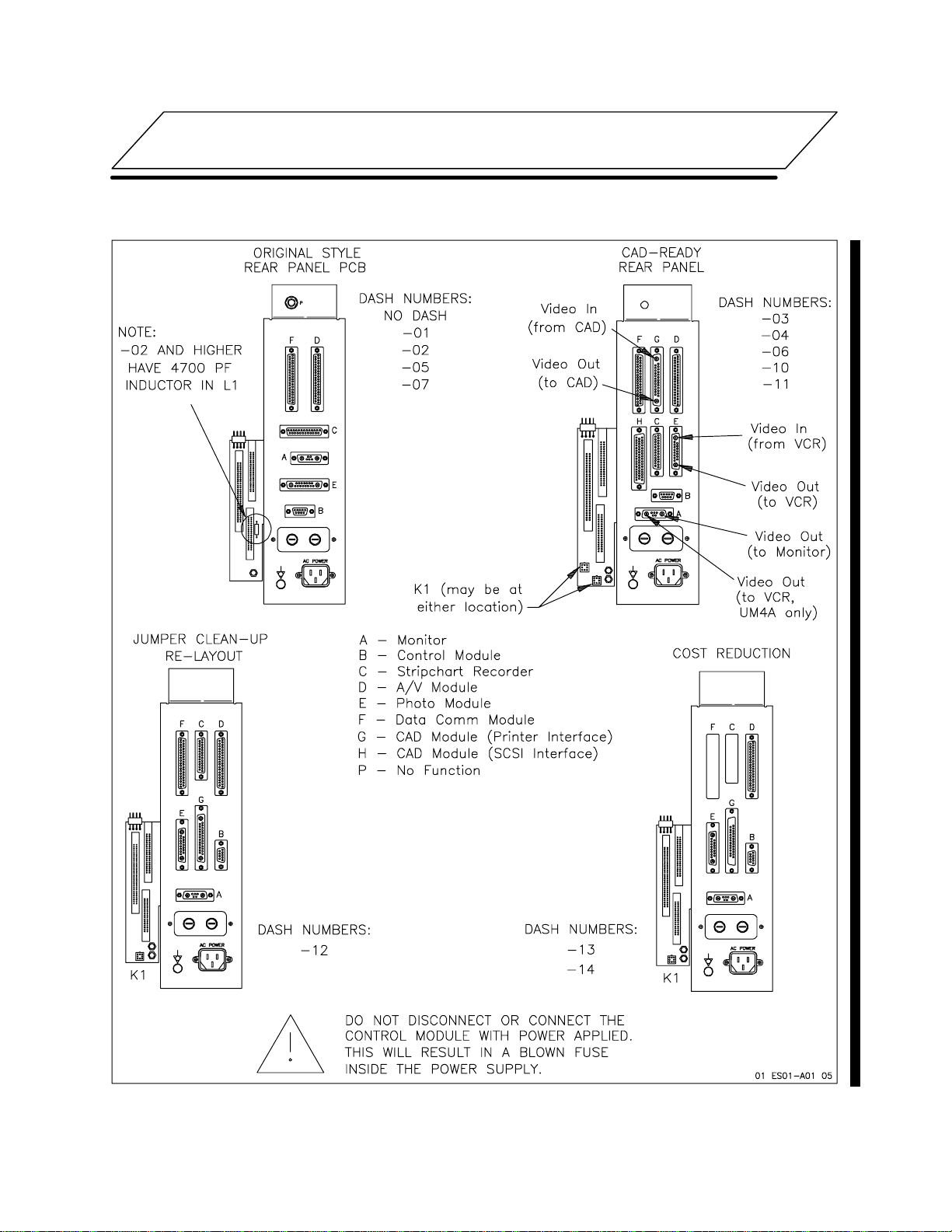
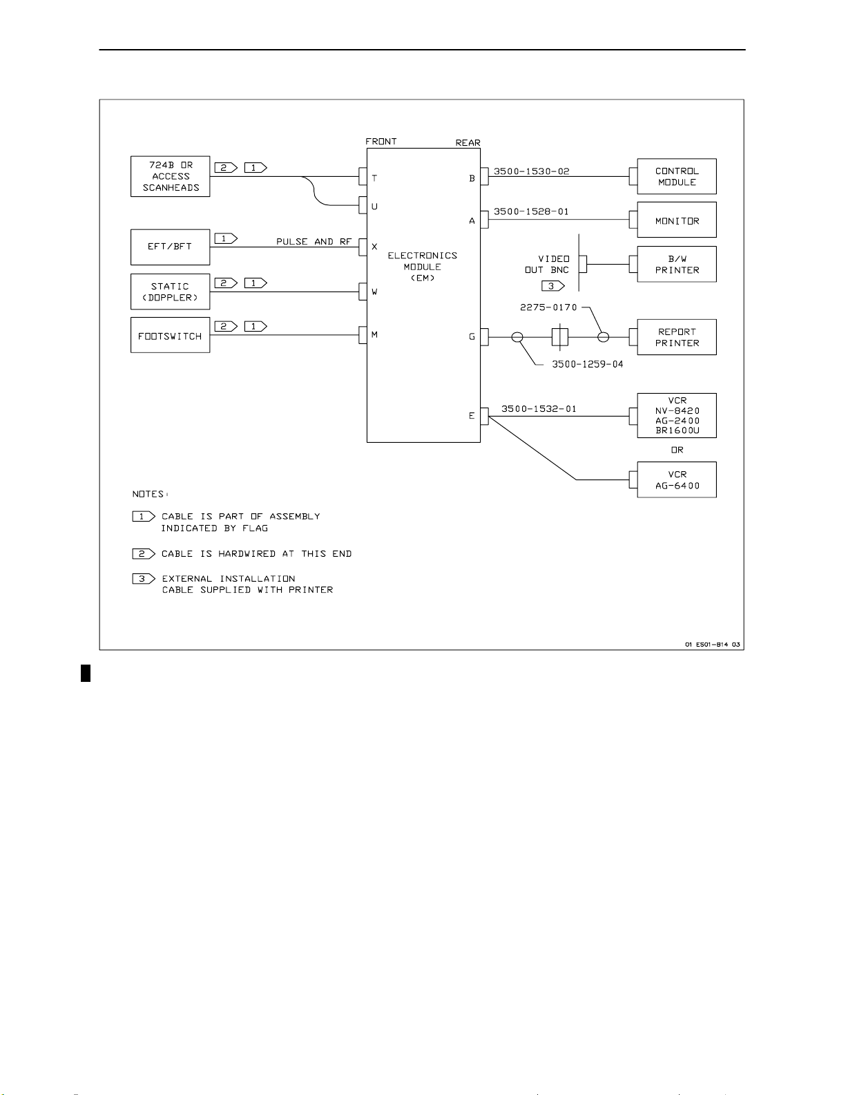
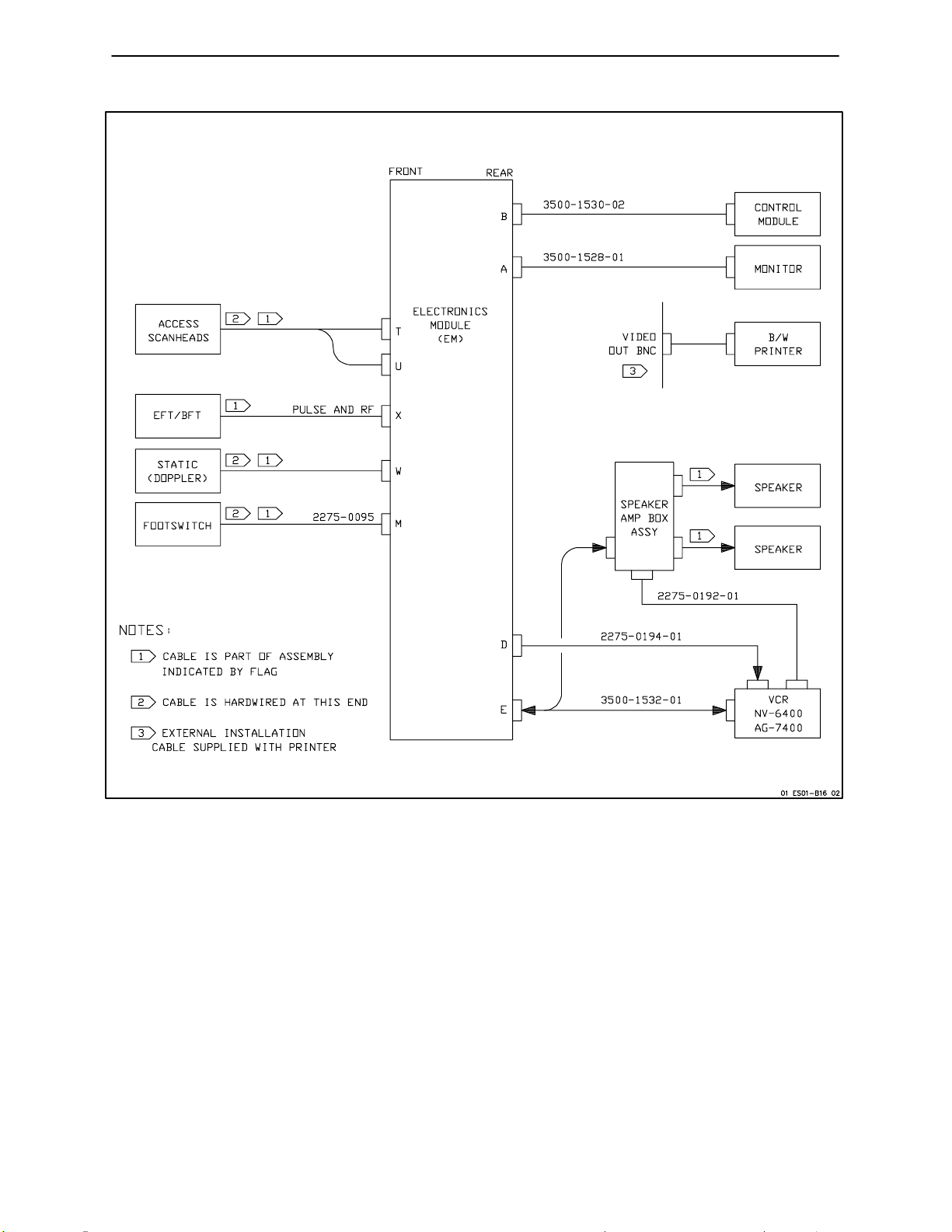
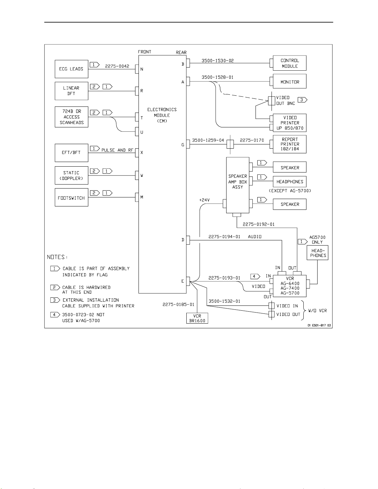
Figure 1C--1. EM Rear Panel Connections
Ultramark 4 Field Service Manual
UM4--01C--1
1C Cabling
UM4--01C--2
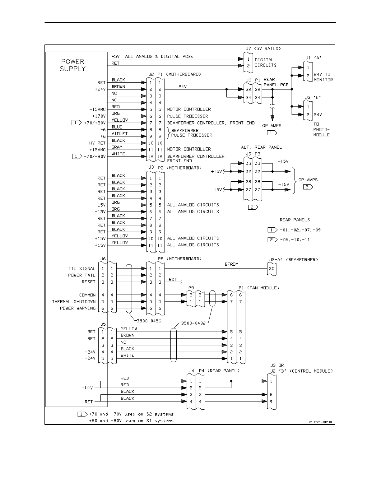
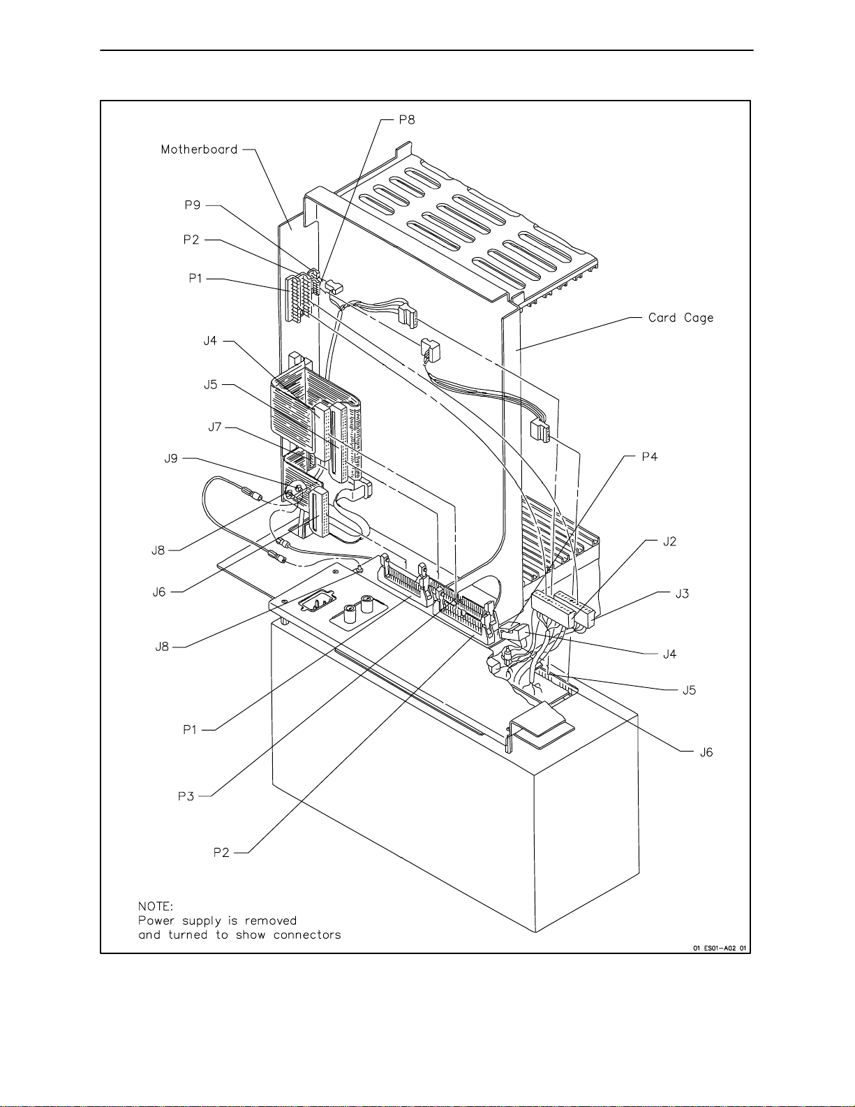
Figure 1C--2. Power Module Connections
Ultramark 4 Field Service Manual
ECG LEADS
LINEAR
DFT
ANNULAR
ARRAY
FRONT
1
2
1
2
1
N
R
S
REAR
A
B
C
2275-0064
2251-0004
2275-0057
8
3
4
4
2275-0102-00
BULKHEAD
1
2275-0101
2251-0003
2275-0057
2275-0122
2
MONITOR
CONTROL
MODULE
LS-8
LINESCAN
RECORDER
724B OR
ACCESS
SCANHEADS
EFT/BFT
STATIC
(DOPPLER)
FOOTSWITCH
NOTES:
1
2
3
4
5
6
7
8
9
2
1
1
2
1
12
CABLE IS PART OF ASSEMBLY
INDICATED BY FLAG
CABLE IS HARDWIRED AT THIS FLAG
ONLY ONE OF THE CABLES
SHOWN MAY BE CONNECTED
TO THIS CONNECTOR
TWO CABLES ARE CONNECTED IN
OEM TO ALLOW SEPARATION OF
NEWER HUMAN FACTORS
MODULE FROM EM
ATTENUATOR CABLE REQUIRED
WITH -04 AND -05 A/V MODULE
PART NUMBER SPECIFIES PANEL
AND CABLE
EITHER DATA COMM OR CAD;
EITHER PHOTO MODULE OR CAD
CABLE SELECTION DEPENDS ON
HF MODULE DASH LEVEL
SEE PARTS, TABLE 8-11
PULSE AND RF
T
U
X
W
M
ELECTRONICS
MODULE
(EM)
D
E
F
G
3500-1259-04
2275-0103
3
2275-0106
2275-0090
3500-0465-01
3500-0915-01
PRINTER
INTERFACE
2275-0092
3
RS232
3500-4036-01
BULKHEAD
AUX VIDEO
PRINTER
2275-0126
D
AUDIO
EO1
EO2
E
F
7
VIDEO
(A/V)
MODULE
VIDEO COPY
INTERFACE
3500-0944-01
PHOTO
MODULE
DATA
COMM
MODULE
CAD
MODULE
G
I
J
2275-0228-01
2275-0088
3
H
22
K
L
3
AUX VIDEO
9
2275-0173
3500-0515
3500-0610
3500-0700-02
3
6
3500-0700-02
3500-4037-01
2275-0176
2275-0129
2275-0170
(ALT 3500-059 2)
2275-0222-02
2275-0109
2275-0121
3500-0623-01
3500-0613
2275-0125
3500-0491
2250-0223
5
2250-0222
5
2250-0223
5
3500-0723-02
VGR 4000
PAGE
PRINTER
MATRIX
1010
LENZAR 2100
MULTI-IMAGE
CAMERA
VIDEO
OUTPUT
DOPPLER
SPEAKERS AND
AMPS
GENERIC
VCR PANEL
MONO DOM
VCR
NV-8420
STEREO DOM
VCR
VR 40A
MONO INTL
VCR
(NV-180 EG)
STEREO VCR,DOM
AG6400,
AG-7400
SMALL
PRINTER
(TP-10)
LARGE
PRINTER
(182 or 320)
PAR. PRINTER
(182 or 320)
HAND
CONTROLLER
VCR
AG 2400
STEREO VCR
(INT)
AG 6200 (INT)
AG 6300 (DOM)
VIDEO GRAPHICS
PRINTER
YP-1810/UP- 850
UP860/UP870
VIDEO COPY
PROCESSOR
P60U
01 ES01-B13 04
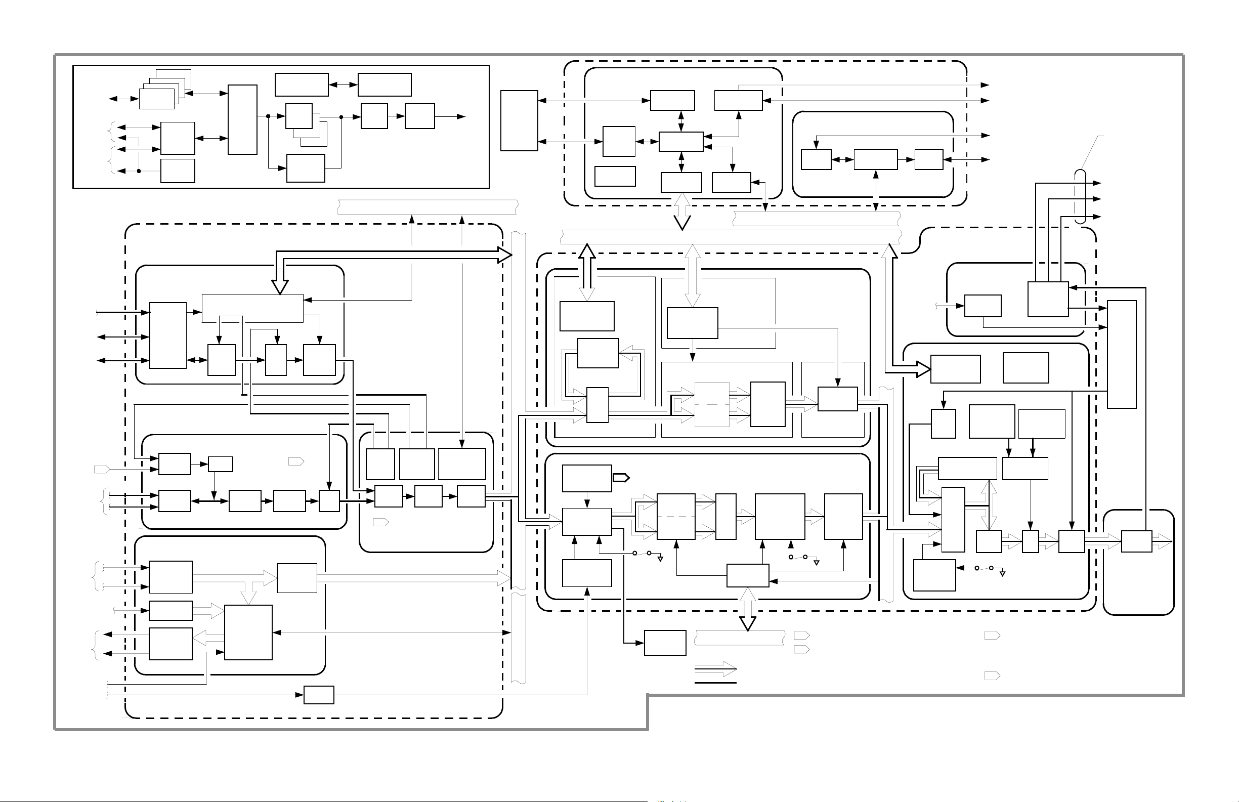
Figure 1C-3. UM-4 Human Factors Cart (HFC) Cabling Diagram
Ultramark 4 Field Service Manual UM4-01C-3Ultramark 4 Field Service Manual
1C Cabling
UM4--01C--4
Figure 1C--4. UM-4A (OB) Cabling Diagram
Ultramark 4 Field Service Manual

1CCabling
Ultramark 4 Field Service Manual
Figure 1C--5. UM-4CV Cabling Diagram
UM4--01C--5
1C Cabling
UM4--01C--6
Figure 1C--6. UM-4PV Cabling Diagram
Ultramark 4 Field Service Manual
1CCabling
Figure 1C--7. UM-4A (Full Feature) and 4A
Ultramark 4 Field Service Manual
PLUS
Cabling Diagram
UM4--01C--7

Section 2A Pre-Installation Requirements
2A--1 Introduction
The purpose of this evaluation is to ensure
a trouble-free installation and to assist the
customer in providing an environment that
supports the reliable performance o f an
ATL ultrasound system. This document is
intended to guide you through a comprehensive inspection that ensures all physical, electrical and environmental
conditions are appropriate for optimum
system operation.
NOTE:
Some parts of this section include
policies, equipment requirements, and
procedures that may apply only to U.S.
field use. For dealers, affiliates, or other
authorized service personnel who do not
use the domesticU.S. servicedocuments,
use your equivalent document, where
applicable.
NOTE:
CID should be presented to, and
reviewed with, the primary service contact and made accessible to both the
equipment user and the CSR.
In addition, system specifications
(
Ta b l e 2 A -- 1
) are included at the end of
this section to assist in evaluating the site.
2A--2 Required Materials
Tool Kit
x
DVM
x
Oscilloscope
x
ONEAC Line Viewer
x
Three-pronged Outlet Tester
x
Measuring Tape
x
ATL General Service Manual
x
(4720-0219-01)
ATL Power Primer (4760-0215-XX)
x
Power Line Data Sticker (4765-0247-XX)
x
Site Evaluation FSR (4765-0298-XX)
x
x
Installation Planning Manual
(4765-0001-XX)
Two documents are used exclusively with
the site evaluation program.
x
A comprehensive Site Evaluation FSR is
used to accurately record and document
all pertinent customer information as
well as the actual site findings. It accommodates evaluating two sites.
x
The Customer Information Directory
(CID) is a resource document that
enables the customer to more easily
communicate with ATL. It also serves as
a convenient file for keeping FSRs, MAs
and other pertinent documentation. The
Ultramark 4 Field Service Manual
2A--3 Initial Customer Contact
In notifying you of a pending new system
delivery, the Customer Support Center
(CSC) will give you as much lead-time as
possible. Although it is our goal to perform
an on-site inspection thirty days or more
prior to system installation, it is not always
possible. For those accounts in which
travel is excessive or costly, or in the event
that you are given less than three weeks
notice before system delivery, exercise
good judgement in determining if you will
do a site evaluation prior to installation. In
either case, conduct some of the site eval-
UM4--02A--1
 Loading...