

Page 1

OM25
USER GUIDE
Page 2

ATL Part No 1/356/001/610
Issue: 03 Nov 2004
Disclaimer
The information contained in this document is confidential to ATL Telecom Ltd. and may not be
disclosed or reproduced in whole or in part without their written consent.
© ATL Telecom Ltd 2004.
Note: The information contained in this document is supplied without liability for errors or
omissions.
ATL Telecom Limited reserves the right to make changes to this document at any time without
notice.
Page 3

3
ATL User Guide
OM25 OOptical MModem
COMPLIANCE NOTES & SAFETY INSTRUCTIONS
Caution: - Hazardous voltages inside the equipment
Safety Instructions:
This apparatus must be installed and maintained by SERVICE PERSONNEL only
There are NO user serviceable parts inside the modem.
The mains plug on the equipment serves as the disconnect device, therefore a socket outlet shall
be installed near the equipment and shall be easily accessible
Caution: - Electrostatic sensitive devices inside the equipment
Electrostatic discharge (ESD) Warning:
Antistatic precautions should be observed at all times.
Power Rating Information - AC unit:
Voltage Range 85V-250V
Current Range 50mA
Frequency Range 50/60Hz
Power Rating Information - DC Unit:
Voltage Range -18V to -72V
Current Range 200mA
Safety Statements classification - NON traffic ports
The AC Mains input has a safety status of PRIMARY CIRCUIT
The OM25 AC unit is defined as a class 1 equipment and must be connected to a reliable earth
connection.
If the mains earth cannot be guaranteed to be PROTECTIVE EARTH, then a PROTECTIVE EARTH
conductor must be connected to the M3 stud on the rear panel of the unit.
The DC input has a safety status of TNV-2
Page 4
ATL User Guide
OM25 OOptical MModem
4
The OM25 DC unit is defined as class II equipment, an EARTH conductor must be connected to
the M3 stud on the rear panel of the unit when using the G.703 interface in accordance with ITUT G.703 requirements.
Statement Safety Statements traffic ports:
The Optical Interface has a safety status of CLASS 1 LASER PRODUCT
The Terminal Port has a safety status of EARTHED SELV.
The G.703 Port Connection Port has a safety status of SELV when connected to Unexposed
Environments:
The G.703 Port Connection Port has a safety status of TNV-1 when connected to Exposed
Environments:
Definitions:
Exposed Environment
A TELECOMMUNICATIONS NETWORK is considered to be an exposed environment if one or more
conditions for an unexposed environment are not fulfilled.
Unexposed Environment
A TELECOMMUNICATIONS NETWORK is considered to be an unexposed environment if the
following conditions apply to all parts of the network.
a) The possible effect of indirect lightning has been reduced by measures described in IEC 61312-
1.
b) The possibility of having different earth potentials has been reduced by connecting all
equipment within the network to the same equipotential bonding system (see HD 384).
c) The possibility of power cross/contact has been reduced (see HD 384).
d) The possibility of induced transients and voltages has been reduced.
Manufacturers Declaration*
ATL Telecom Limited declares that this product is in conformity
with the essential requirements of the 'R&TTE directive 1999/5/EC'.
*A copy of the Declaration of Conformity is available upon request from ATL Telecom Ltd.
Page 5

5
ATL User Guide
OM25 OOptical MModem
1 INTRODUCTION 9
2 EXAMPLE APPLICATIONS 10
3 CONSTRUCTION 11
3.1 FRONT PANEL 11
3.1.1 LEDS 11
3.1.1.1 STATUS 11
3.1.1.2 OPTICAL 11
3.1.1.3 INTERFACE 11
3.1.1.4 MASTER (GREEN) 12
3.1.1.5 TEST (RED) 12
3.1.1.6 LOOPS (AMBER) 12
3.1.2 BUTTONS 12
3.1.3 TERMINAL PORT 12
3.2 REAR PANELS 12
3.2.1 DC VARIANT 12
3.2.2 AC VARIANTS 13
3.2.3 REAR CONNECTORS COMMON TO AC & DC VARIANTS 13
4. INSTALLATION 14
4.1 PROTECTIVE EARTH 14
4.2 POWER ON SEQUENCE 14
4.3 DEFAULT SETTINGS 15
5. INTERFACES & TIMING OPTIONS 16
5.1 V.35 INTERFACE 16
5.1.1 USER RATE 16
5.1.2 END TO END SIGNALLING 16
5.1.3 SIGNALLING CIRCUIT OPTIONS 16
5.1.4 EXTERNAL TIMING 16
5.1.5 ENABLE LOOPS 17
5.1.6 FUNCTIONAL OPERATION 17
5.2 G.703 INTERFACE 18
5.2.1 TIMING MODES 18
Page 6

ATL User Guide
OM25 OOptical MModem
6
5.2.1.1 THROUGH TIMING 18
5.2.1.2 LOCAL TIMING 18
5.2.1.3 LOOP TIMING 19
5.2.2 FRAMING MODES 19
5.2.2.1 UNSTRUCTURED MODE 19
5.2.2.2 STRUCTURED MODE 19
5.2.3 PERFORMANCE 20
6. CONFIGURATION VIA THE TERMINAL PORT 21
6.1 LOGIN 21
6.2 LOGOUT 24
6.3 MENU SCREENS 25
6.3.1 NAVIGATION SCREENS 25
6.3.2 INFORMATION SCREEN 26
6.3.3 CONFIGURATION SCREENS 27
6.3.3.1 ENTERING INFORMATION 27
6.3.3.2 MOVING BETWEEN CHECK BOXES 27
6.3.3.3 TURNING FUNCTIONS ON AND OFF 27
6.3.3.4 HOW RADIO BUTTONS WORK 28
6.4 MENU STRUCTURE 29
6.5 ALARMS 30
6.5.1 ALARM STATUS SCREEN 30
6.5.2 ALARM HISTORY SCREEN 32
6.6 CONFIGURATION 34
6.6.1 MASTER/SLAVE CONFIGURATION 34
6.6.2 USER PORT CONFIGURATION 36
6.6.2.1 V35 USER PORT 36
6.6.2.2 G703 USER PORT 37
6.6.3 REBOOT 38
6.6.4 SYSTEM 39
6.6.5 SUBSYSTEM NAMES 40
6.6.6 MONITORING 41
Page 7

7
ATL User Guide
OM25 OOptical MModem
6.6.7 SERIAL COMMUNICATIONS 43
6.6.7.1 PROCEDURE TO FOLLOW WHEN CHANGING SETTINGS 44
6.6.8 FRONT PANEL 45
6.7 INFORMATION 46
6.8 PERFORMANCE 47
6.8.1 PERFORMANCE OPTICAL LINES 47
6.8.2 PERFORMANCE USER PORT 48
6.9 SECURITY 49
6.10 TEST 50
7. CONFIGURATION VIA THE FRONT PANEL BUTTONS 51
7.1 INTRODUCTION 51
7.2 OPERATION 51
7.2.1 GENERAL 52
7.2.2 G.703 OPTIONS 53
7.2.3 V.35 OPTIONS 54
7.3 KEYPAD LOCK 54
7.4 AUXILIARY PORT OPERATION 54
8. SPECIFICATIONS 55
8.1 DIMENSIONS 55
8.2 TRANSMISSION PERFORMANCE 55
8.2.1 JITTER 55
8.2.2 TRANSMISSION RANGE 55
8.3 AC POWER INLET 55
8.4 DC POWER INLET 56
8.5 DC MAINS CABLE 56
8.6 OPTICAL CONNECTIONS 57
8.6.1 SAFETY WARNING 57
8.6.2 OPTICAL CONNECTOR CLEANING 57
8.6.3 FC.PC CONNECTOR 57
8.6.4 SC CONNECTOR 58
Page 8

ATL User Guide
OM25 OOptical MModem
8
8.7 INTERFACE CONNECTIONS 58
8.7.1 G.703 120 OHM INTERFACE 58
8.7.2 G.703 75 OHM INTERFACE 58
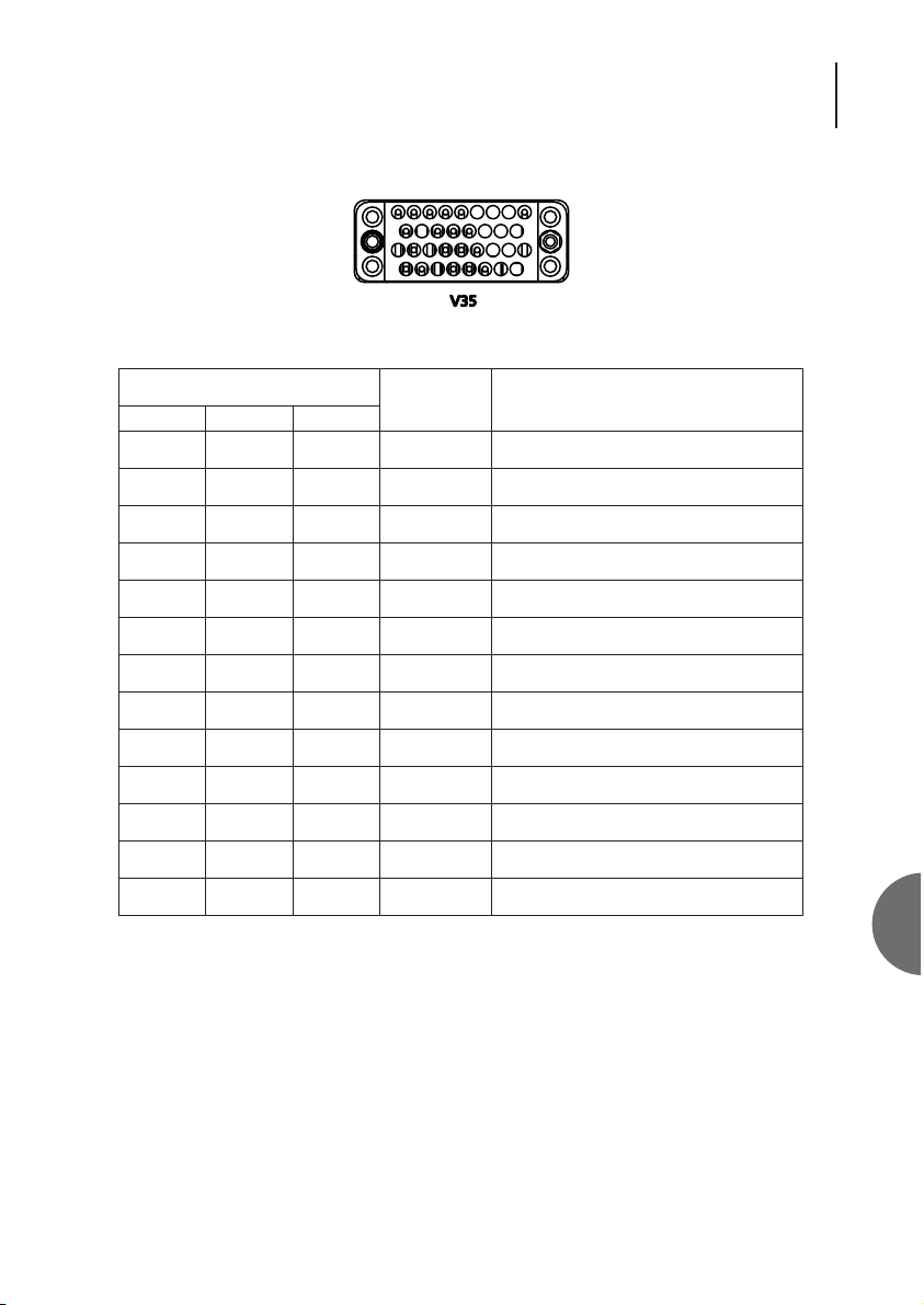
8.7.3 V.35 INTERFACE 59
8.7.4 V.35 EXTERNAL TIMING ADAPTOR CABLE PINOUT 60
8.8 TERMINAL CONNECTION 61
8.9 ENVIRONMENTAL 62
8.9.1 TRANSPORTATION 62
8.9.2 STORAGE 62
8.9.3 OPERATIONAL 62
9. ORDERING INFORMATION 63
9.1 OM25 AC POWERED 63
9.2 OM25 DC POWERED 63
9.3 ACCESSORIES 63
Page 9
9
ATL User Guide
OM25 OOptical MModem
1
1 INTRODUCTION
This User Guide applies to the OM25 optical modem designed and manufactured by ATL Telecom
Limited in the U.K. It provides guidance for installation, commissioning and operation of the
modem as well as reference information covering maintenance, specification and compliance.
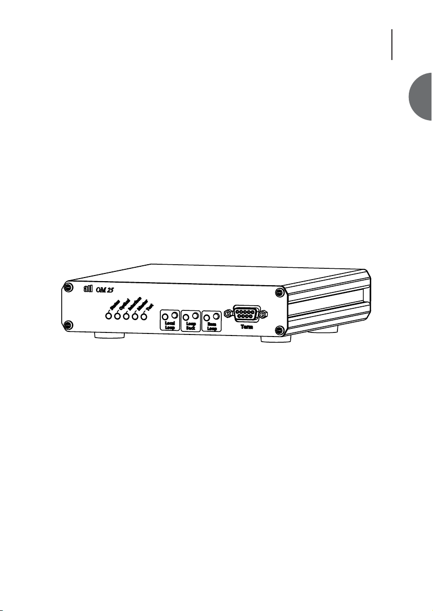
OM25 is an optical standalone modem providing a single V35 or G703 interface to the user. It
delivers framed & unframed E1, fractional E1 and N*64kbps services. Protocol conversion (e.g.
G.703 at the CO and V.35 at the CPE) is handled automatically.
The OM 25 Long Haul version can transmit data typically up to 75km. The OM25 Short Haul version
can transmit data typically up to 15km.
Management control is provided locally via the RS232 connector. Alternatively the OM25 can be
set-up locally using the loop buttons on the front of the unit.
Power is via a universal 85 to 250V ac connector or a -48V dc connector.
Figure 1 OM25
Page 10
ATL User Guide
OM25 OOptical MModem
10
2 EXAMPLE APPLICATIONS
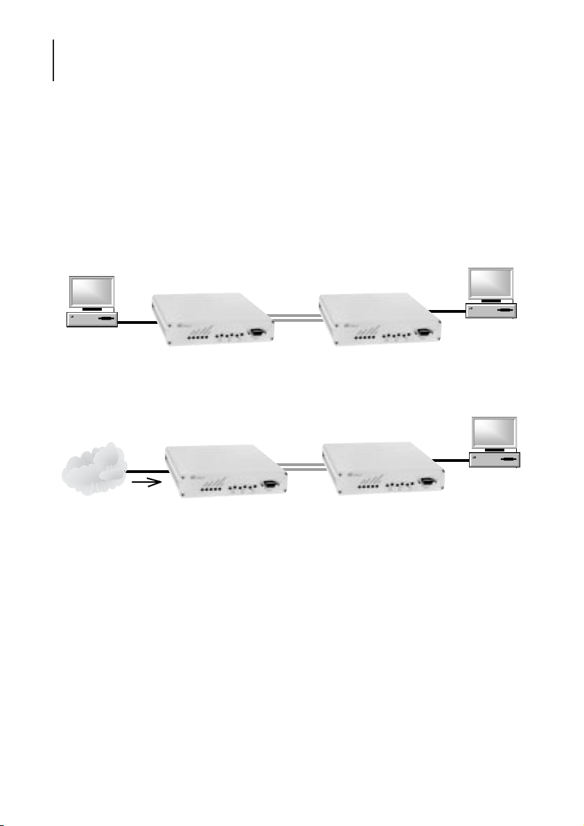
Two OM25s may be linked via a dual fibre single mode optical link to provide end-to-end electrical
interfaces, either of like type (ie G703 to G703) or of different type (G703 to V35). One of the units
is configured as timing source (CO) , the other as timing sink (CPE).
Additionally, one of the units is configured as ‘master’, the other as ‘slave’. The ‘master’ unit is the
source of link management and is able to configure and monitor the slave settings but not vice
versa.
Either master or slave can be set to be CO.
A simple point-to-point network between two terminals is shown in Fig 2.
Figure 2
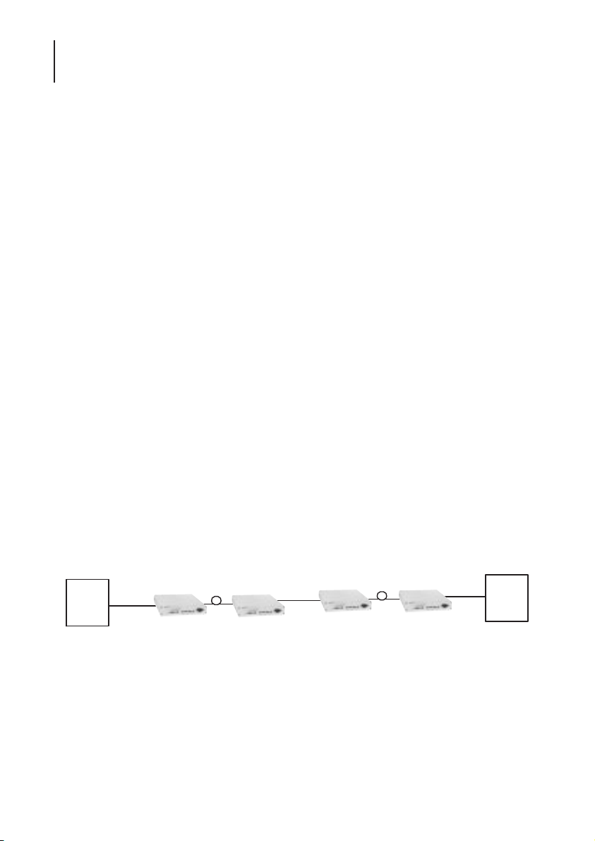
A tandem section, where the modems are connected in series with another transmission system or
equipment that is the source of timing, is shown in Fig 3.
Figure 3
OM25 - CO OM25 - CPE
G.703
or V.35
Optical Fibre
Cables
G.703
or V.35
Network
OM25 - CO OM25 - CPE
G.703
or V.35
Timing
Optical Fibre
Cables
G.703
or V.35
Page 11
11
ATL User Guide
OM25 OOptical MModem
3
3 CONSTRUCTION
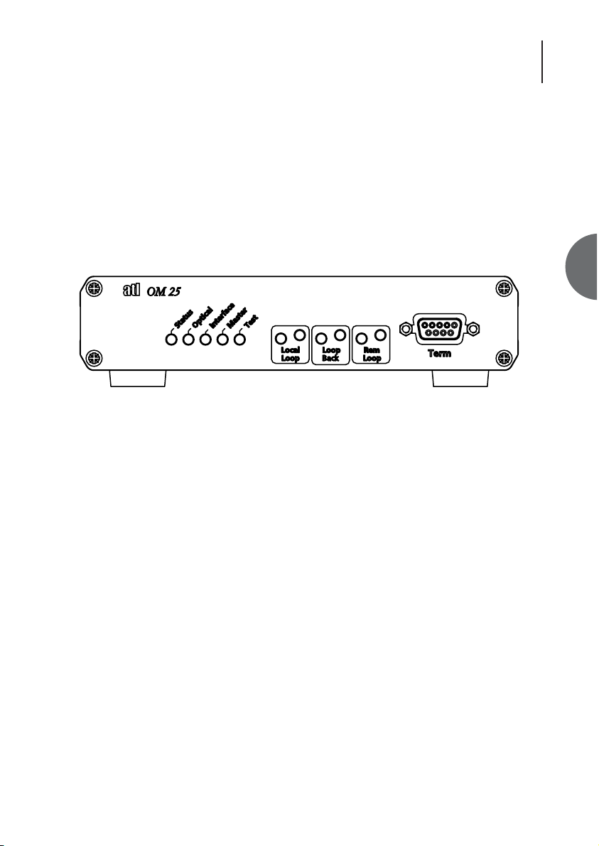
The front panel controls have a dual purpose. For normal operation, the LED indicators display
status information and the push buttons are used for applying test loops. These controls can
however, also be used to configure the modems without the need to plug in a VT100 terminal or
PC. To do this, the front panel controls must be enabled for "Full Control" (default setting) and
the unit set to Programming Mode, section 7.
3.1 FRONT PANEL
The front panel of the OM25 contains a RS232 9 way D-Type terminal connection, eight status
LEDs and three front panel buttons
Figure 4 Front Panel
3.1.1 LEDS
3.1.1.1 STATUS
Red - An urgent alarm is present in the system.
Amber - A non-urgent alarm is present in the system.
Green - No alarms are present in the system.
3.1.1.2 OPTICAL
Red - An urgent alarm is present on the Optical Port.
Amber - A non-urgent alarm is present on the Optical Port.
Green - No alarms are present on the Optical Port.
3.1.1.3 INTERFACE
Red - An urgent alarm is present on the User Interface.
Amber - A non-urgent alarm is present on the User Interface.
Green - No alarms are present on the User Interface.
In the ‘green’ state the state of the received data (data output from the modem on the user
interface) is indicated. The LED is green for 1’s and off for 0’s.
11
Page 12
ATL User Guide
OM25 OOptical MModem
12
3.1.1.4 MASTER (GREEN)
When lit, this LED indicates that the unit has been configured to operate as a management
'master'. The default setting is for the unit to be a 'slave', in which case the LED will be turned off.
3.1.1.5 TEST (RED)
This will be illuminated whenever a loop test is active on the unit.
3.1.1.6 LOOPS (AMBER)
These will be illuminated whenever a test loop has been selected.
3.1.2 BUTTONS
There are three buttons on the front of the OM25, Local Loop, Loop Back and Remote Loop. In
Normal mode the buttons can be used to setup various test loops. In Programming mode the
buttons are used to configure the OM25, refer to section 7.
3.1.3 TERMINAL PORT
The terminal port allows the OM25 to be configured via a VT100 terminal or PC running a VT100
emulation program.
Alternatively, the port may be used as an auxilary RS-232 link carried transparently across the fibre.
See section 7.4.
3.2 REAR PANELS
The OM25 is supplied with either a -48V d.c. or a 110/230V a.c. power supply connector.
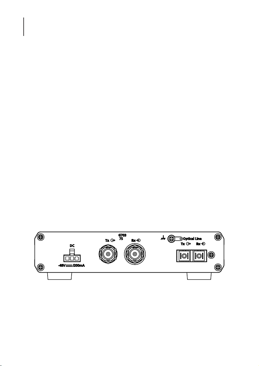
3.2.1 DC VARIANT
The DC unit
Figure 5 OM25 DC G.703 75ΩΩwith SC Optical Connectors
Ω
Page 13
13
ATL User Guide
OM25 OOptical MModem
3
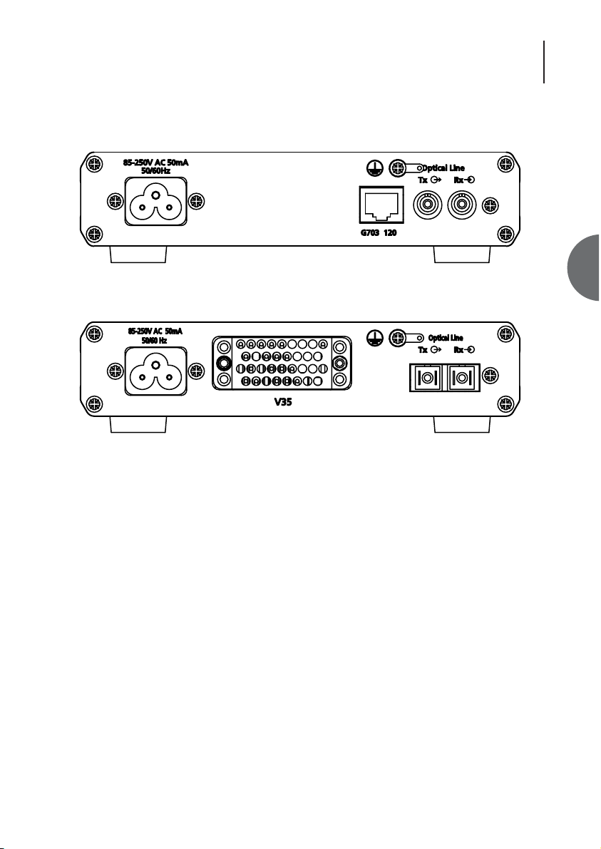
3.2.2 AC VARIANTS
Figure 6 OM25 AC G.703 120ΩΩwith FCPC Optical Connectors
Figure 7 OM25 AC V.35 with SC Optical Connectors
3.2.3 REAR CONNECTORS COMMON TO AC & DC VARIANTS
Optical Connector (depending on variant)
User Data Ports (depending on variant)
OM25 Long Haul G.703 75 ohms FC/PC & 2*BNC
OM25 Long Haul G.703 120 ohms FC/PC & RJ45
OM25 Long Haul V.35 FC/PC & 34 way MRAC
OM25 Short Haul G.703 75 ohms SC & 2*BNC
OM25 short Haul G.703 120 ohms SC & RJ45
OM25 Short Haul V.35 SC & 34 way MRAC
Ω
Page 14

ATL User Guide
OM25 OOptical MModem
14
4. INSTALLATION
This chapter describes the basic steps that are required to set up a system using the OM25 Optical
modem.
It is recommended that if two desktop units are to be connected they should be tested back to
back to check for operation before deployment.
Choose a cool, dry location away from direct sunlight. A cold, air conditioned room will give
maximum service life.
4.1 PROTECTIVE EARTH
If a G.703 port needs to be connected to a circuit that is defined as TNV, then a protective earth
must be connected to the earth bond stud on the rear panel. See the Safety Statements at the
front of this User Guide.
4.2 POWER ON SEQUENCE
The power up sequence will begin after power is applied.
Desktop units require a -48V dc or 110/230V ac input (depending on the variant).
The unit must be connected to a protective earth using a suitable bonding conductor.
On the desktop unit, there are eight LED’s: Status, Optical, Interface, Master, Test, Local loop, Loop
back and Remote loop. When power is applied to the unit, the front panel LED’s are illuminated
as follows;
1. Test LED will illuminate for around 5 seconds.
2. Test LED extinguished, Status and Optical LED’s should then be illuminated. The Master LED may
be illuminated if the unit is set to master. Plus the Interface LED may be illuminated if 1’s are
present.
The unit will then be in a ready state for customer configuration.
Page 15

15
ATL User Guide
OM25 OOptical MModem
4
4.3 DEFAULT SETTINGS
The OM25 is supplied set with the following default settings.
General
Mode Slave CPE
User Port Rate n = 32, 2048kbps
V.35 Interface
Enable Loops Enabled
End to End Signalling Off
Circuits 106, 107 & 109 On
Timing Loop
G.703 Interface
Timing Through
Frame Unframed
TS0 Regenerated
Channelisation Disabled
Page 16
ATL User Guide
OM25 OOptical MModem
16
5. INTERFACES & TIMING OPTIONS
5.1 V.35 INTERFACE
5.1.1 USER RATE
User rates from 64K to 2304K (n = 1 to 36) can be configured; however, if the remote end is using
G703, the maximum data rate at the V35 end is 2048K (n = 32).
5.1.2 END TO END SIGNALLING
When On
Circuits 105 and 109 are transmitted end-to-end across the link, ie the state of 105 at one end is
mirrored by the state of 109 at the other.
When Off
Circuits 105 and 109 are not transmitted across the link. Their states are only relevant to the local
unit.
5.1.3 SIGNALLING CIRCUIT OPTIONS
106 Normal / Set On
107 Normal / Set On
109 Normal / Set On
Circuits 106, 107 and 109 can act according to X21bis V35, or can be set permanently ON.
5.1.4 EXTERNAL TIMING
Tandem sections require an adaptor cable (not supplied, wiring information shown in section 8.7.4)
so that two OM25s can be plugged together back to back via their user interfaces. Selecting
External Timing ON on one of the units will then allow the two CO’s to lock timing.
Fig 8 - External Timing
OM25
16
Terminal
G703 / V35
OM25
CPE
Fibre
CO
Ext timing
Adapter
cable
OM25
CO
Fibre
OM25
CPE
G703 / V35
Terminal
Page 17
17
ATL User Guide
OM25 OOptical MModem
5
5.1.5 ENABLE LOOPS
When OFF, loop activation via control lines 140 and 141 is disabled. Also incoming V54 patterns
from the fibre are ignored. This allows end to end loop activation in tandem sections. For example,
the two modems connected by an adaptor cable in Fig 8 would have this option set to OFF, so that
the far left-hand modem could set a remote loop on the far right-hand unit via V54.
Loop activation is still possible via front panel / VT100.
5.1.6 FUNCTIONAL OPERATION
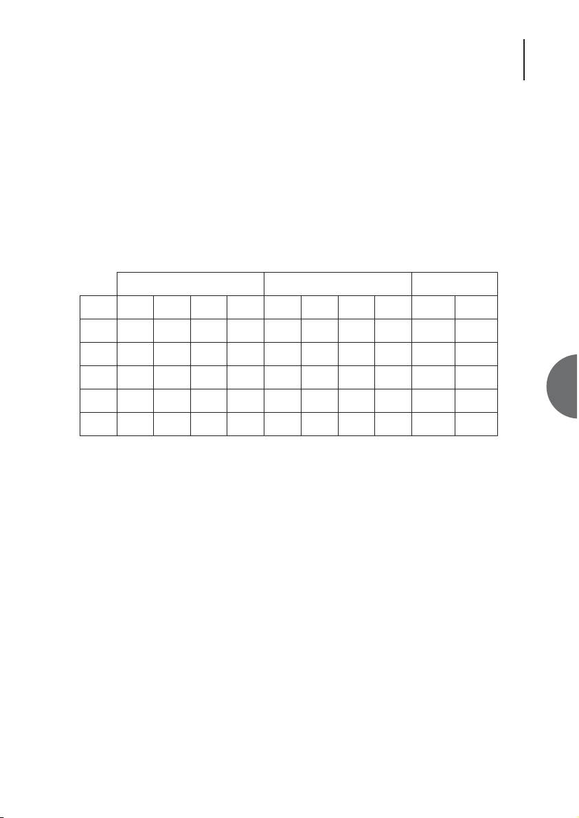
When circuits 105 and 109 are being transferred across the link (End to End signalling ON), the
behaviour is as follows:
Table 1 - V35 operation
'Tx sig' refers to the state of the signalling bit sent on the fibre to the remote end. Similarly, 'Tx
data' refers to the state of the data sent on the fibre to the remote end.
'Rem' is used to denote the state of the appropriate signal at the remote end.
For '106 Set On', 106 is ON in all cases. This is the factory default. When 106 is following 105,
there is a delay of 16ms in the OFF-to-ON transition.
For '107 Set On', 107 is ON in all cases. This is the factory default.
For '109 Set On', 109 is ON in all cases. This is the factory default.
When circuits 105 and 109 are not transferred across the link (End to End signalling OFF), 109 and
Tx sig are ON in line 5. This is the factory default.
Switching circuit 140 ON triggers a V54 sequence to activate a remote loop. Circuit 141 activates
a local loop.
Circuit 142 is active when local loop or loopback is active and also at both ends when remote loop
is active.
Conditions V.35 Outputs Line Outputs
Loop
Loc
In
105
Case 106 104109107 Tx Sig Tx Data
Sync
X OffOnX1 105 103105On Off 1
X OnOnYes2 105 103105On Rem 105 Rem 103
X OnOffYes3 Off 1OffOff Rem 105 Rem 103
X OffOffNo4 Off 1OffOff X X
X OffOffYes5 105
Back
Loop
On 105 103
105
103
Rem
Rem
Page 18
ATL User Guide
OM25 OOptical MModem
18
5.2 G.703 INTERFACE
5.2.1 TIMING MODES
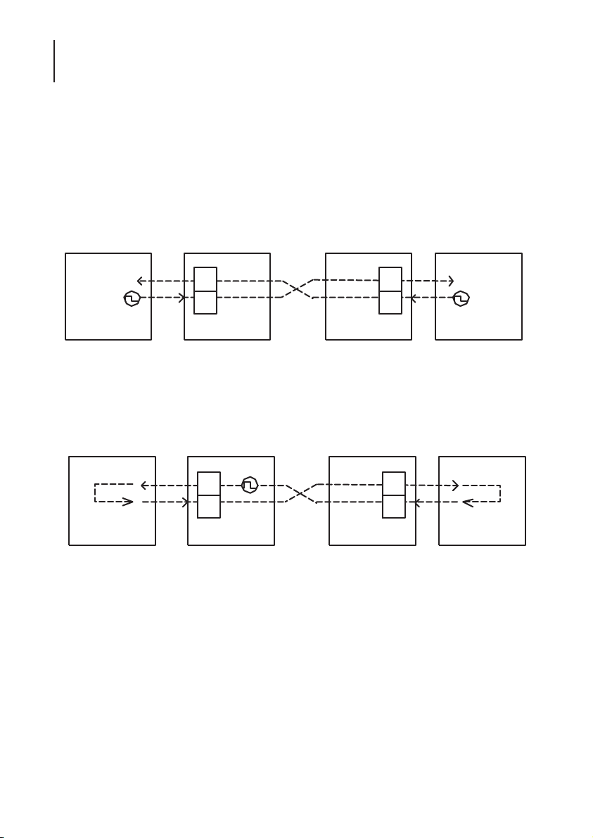
There are three timing modes - Through, Local and Loop.
5.2.1.1 THROUGH TIMING
Through mode is plesiochronous - the two directions have independent timing and can transfer at
differing rates. The connected terminals are the source of timing. Each modem receives timing
from its terminal and passes it to the far end.
Fig 9 - Through timing
5.2.1.2 LOCAL TIMING
In Local timing mode, the clock source inside the CO is the reference clock for the system.
Transmission on the fibre is locked to this clock. Both terminals lock to this clock and return the
clock to the OM25s.
Fig 10 - Local timing
Timing source
Terminal
G703
Tx
Rx
CO
CPE
G703
Tx
Rx
Timing source
Terminal
Timing looped
Terminal
G703
Tx
Rx
Timing source
CO
CPE
G703
Tx
Rx
Timing looped
Terminal
Page 19
19
ATL User Guide
OM25 OOptical MModem
5
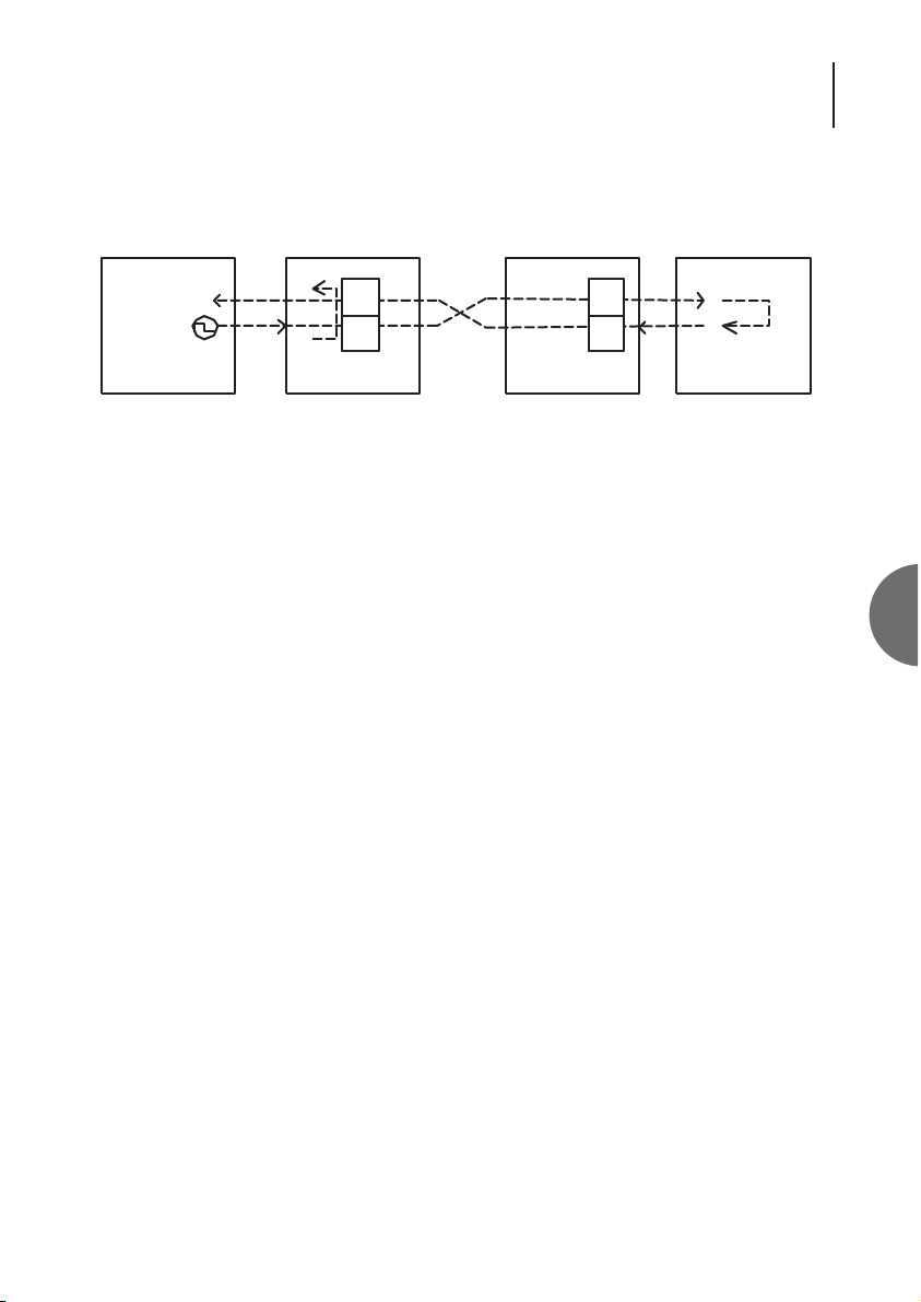
5.2.1.3 LOOP TIMING
In Loop timing mode, the reference clock for the system is provided by the terminal (or network)
connected to the CO.
Fig 11 - Loop timing
The timing mode in the CPE depends on that selected in the CO:
CO Through CPE Through
CO Local CPE Local
CO Loop CPE Local
5.2.2 FRAMING MODES
There are two framing modes - unstructured and structured.
5.2.2.1 UNSTRUCTURED MODE
In unstructured mode, the user data passes transparently through the system. There are no Loss of
Frame Alignment (LOFA), Alarm Indication Remote (AIR) or Alarm Indication Signal (AIS) alarms.
The only alarm relevant to this mode is the Loss of Signal (LOS).
5.2.2.2 STRUCTURED MODE
In structured mode, the modem aligns to the incoming G703 frame from the terminal and extracts
the data from the selected timeslots. It also generates a G703 frame towards the terminal and
inserts the data payload into the selected timeslots.
LOFA is raised if the modem cannot achieve frame lock. Recognition of this alarm complies with
G706.
AIS is raised if there are less than 3 zeros in 512 bits on the G703 interface.
AIR is raised if bit 3 in the Not Frame Alignment Word (NFAW) is set to 1 for 3 consecutive
occurrences.
CRCs may be enabled or disabled. When enabled, errored blocks are indicated back to the terminal
by use of the E bits in timeslot 0. The CRC Fail alarm is active if CRC multiframe alignment cannot
be attained.
Timing
G703
looped
Timing source
Terminal
Tx
Rx
CO
CPE
G703
Tx
Rx
Timing looped
Terminal
Page 20

ATL User Guide
OM25 OOptical MModem
20
The CAS multiframe may be enabled or disabled. When enabled, validation of the incoming CAS
multiframe signal in TS16 is performed. The outgoing TS16 contains a generated multiframe
incorporating idle signal codes. There is no processing of signalling data.
Individual timeslots may be selected for transmission using the DS0 selection page on the VT100
screen, however this function cannot be accessed using the front panel.
TS0 is always selected; it is either regenerated by the OM25 or passed transparently (inverted) in
both directions. It is possible to have different timeslots configured at the two ends for mixed
timeslot mapping.
5.2.3 PERFORMANCE
The following performance attributes may be viewed on the VT100 User Performance screen:
Errored Seconds
Severely Errored Seconds
Unavailable Seconds
Severely Errored Frame Seconds
Line Errored Seconds
These are derived from RFC2495, the E1 MIB definition document.
Page 21

21
ATL User Guide
OM25 OOptical MModem
6
6. CONFIGURATION VIA THE TERMINAL PORT
6.1 LOGIN
The OM25 can be configured via the terminal port on the front of the unit. Connect a VT100
terminal (or a PC running a Tera Term emulation program) to the 9-way Terminal port. Configure
the serial port settings of the VT100 terminal or Tera Term to 19,200 baud, 8 bits, no parity, 1 stop
bit and Xon/Xoff.
The following screen will be displayed once the the OM25 has completed its power-on sequence.
Press the spacebar to display the Login screen.
OOOOOOO MM MM 22222 5555555555
OOOOOOOOOOO MMM MMM 22 22 55
OOO OOO MMMM MMMM 22 22 55
OO OO MM MM MM MM 22 55
OO OO MM MMMM MM 22 55555555
OO OO MM MM MM 22 55
OO OO MM MM 22 55
OO OO MM MM 22 55 55
OOO OOO MM MM 22 55 55
OOOOOOOOOOO MM MM 22 55 55
OOOOOOO MM MM 2222222222 555555
Press space-bar to continue
Page 22

ATL User Guide
OM25 OOptical MModem
22
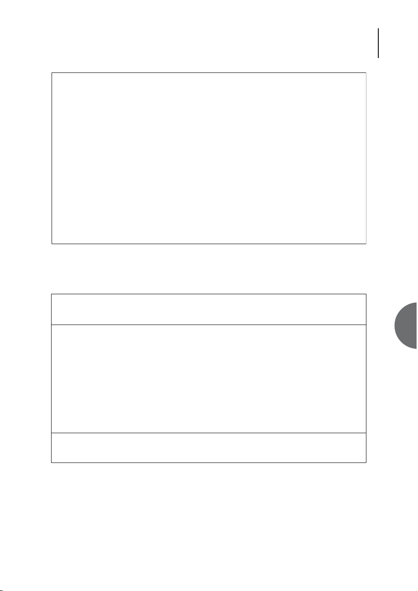
You can now login using one of three modes
Configuration Mode - Allows the user full access to configure the OM25. To access this mode press
‘C’ then <return> to enter this mode
Test Mode - This is a limited access mode that only allows the user to setup test loops. To access
this mode press ‘T’ then <return> to enter this mode
Read-Only Mode - This is a limited access mode that only allows the user to view the current status
of the unit. To access this mode press ‘R’ then <return> to enter this mode
The Screen will now prompt you to enter a password. There is no default password. Press the
<return> key.
OOOOOOO MM MM 22222 5555555555
OOOOOOOOOOO MMM MMM 22 22 55
OOO OOO MMMM MMMM 22 22 55
OO OO MM MM MM MM 22 55
OO OO MM MMMM MM 22 55555555
OO OO MM MM MM 22 55
OO OO MM MM 22 55
OO OO MM MM 22 55 55
OOO OOO MM MM 22 55 55
OOOOOOOOOOO MM MM 22 55 55
OOOOOOO MM MM 2222222222 555555
Login (Configuration, Test, Read-Only) :
Page 23
23
ATL User Guide
OM25 OOptical MModem
6
A help screen is now displayed explaining the operation required to set the various management
fields. Press <y> to skip this screen the next time you login, otherwise press <n>.
The Main Menu screen will now be displayed.
OOOOOOO MM MM 22222 5555555555
OOOOOOOOOOO MMM MMM 22 22 55
OOO OOO MMMM MMMM 22 22 55
OO OO MM MM MM MM 22 55
OO OO MM MMMM MM 22 55555555
OO OO MM MM MM 22 55
OO OO MM MM 22 55
OO OO MM MM 22 55 55
OOO OOO MM MM 22 55 55
OOOOOOOOOOO MM MM 22 55 55
OOOOOOO MM MM 2222222222 555555
Login (Configuration, Test, Read-Only) : *
Password :
OM25 Thur 01 Apr 2004 00:25:18
Main Menu
Urgent Alarm:On Non-Urgent Alarm:Off
A Alarms
C Configuration
I Information
L Logout
P Performance
S Security
T Test
Type selection:
F1 Help
Page 24

ATL User Guide
OM25 OOptical MModem
24
6.2 LOGOUT
You can only logout when the main menu is displayed. Press the F4 function key to close the
existing menu or option screen and open the main menu screen
Press <L> to initiate the logout process.
The screen will the prompt you to to select ‘y’ on ‘n’. Press <y> to logout or press ‘n’ to return to
the main menu.
If the monitoring mode has been set to off (default setting) then the following message will be
displayed for around 5 seconds before the screen reverts to the initial OM25 screen.
If the monitoring mode has been set to ON then the screen will display any alarms as they are
generated
OM25 Thur 01 Apr 2004 00:51:16
Main Menu
Urgent Alarm:Off Non-Urgent Alarm:On
A Alarms
C Configuration
I Information
L Logout
P Performance
S Security
T Test
Type selection:L
Are you sure ? (y/N)
Monitoring Mode is off.
Page 25
25
ATL User Guide
OM25 OOptical MModem
6
6.3 MENU SCREENS
There are 3 types of menu screens; navigation screens that guide the user down through the menu
topology, configuration screens that allow the user to turn functions ON and OFF, and information
screens that provide information on the status of the unit.
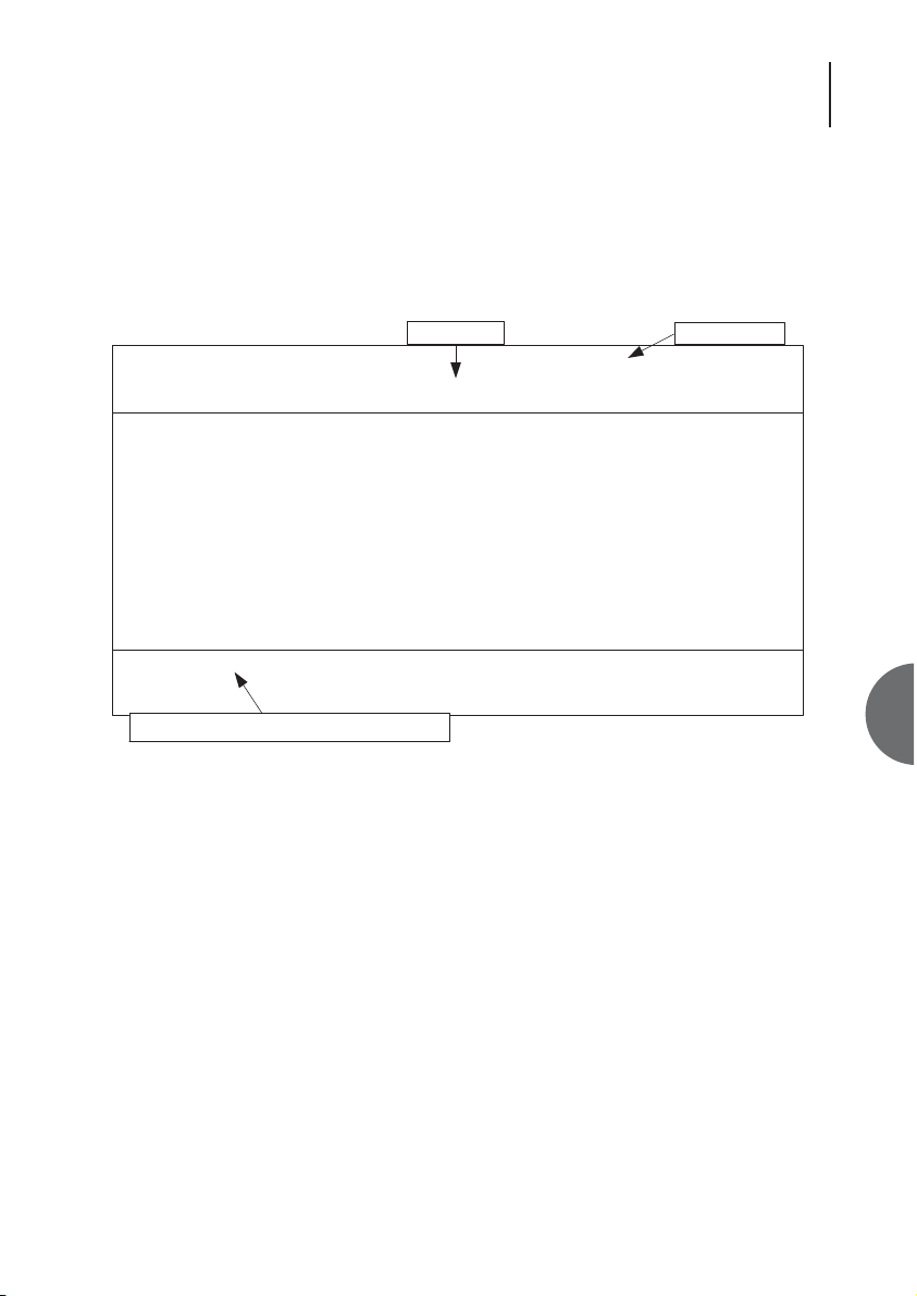
6.3.1 NAVIGATION SCREENS
Pressing the appropriate key activates its associated menu. There is no need to press <return> (In
fact pressing <return> will, in most cases, have the undesired effect of exiting the selected screen).
Screen name Time and date
OM25 Thur 01 Apr 2004 00:38:20
Configuration Menu
Urgent Alarm:On Non-Urgent Alarm:Off
M Master/Slave
U User Port
R Reboot
S System
N Subsystem Names
O Monitoring
C Serial Communications
F Front Panel
Type selection:
F1 Help F3 Previous Menu F4 Main Menu
Functions keys change as you change screens
Page 26

ATL User Guide
OM25 OOptical MModem
26
6.3.2 INFORMATION SCREEN
This screen provides version, alarm and performance information about the system. It is particularly
useful in helping locate problems.
A master unit can view information about itself and about the remotely connected slave unit. A
slave unit can only view its local information.
OM25 Thu 01 Jan 1970 00:03:33x
Performance > Optical
Urgent Alarm:On Non-Urgent Alarm:On
Subsystem: Slave View: Local Statistics
Table | ES | SES | UAS | BBE | Time Elapsed
Current | 0 | 0 | 212 | 0 | 212
Total | 0 | 0 | 0 | 0 |
Interval | ES | SES | UAS | BBE | Valid
1 | 0 | 0 | 0 | 0 | No
2 | 0 | 0 | 0 | 0 | No
3 | 0 | 0 | 0 | 0 | No
4 | 0 | 0 | 0 | 0 | No
5 | 0 | 0 | 0 | 0 | No
6 | 0 | 0 | 0 | 0 | No
Press Escape to Exit
F1 Help F2 View F3 Previous Menu F4 Main Menu F5 Next Interface
F6 Previous Interface F9 Next Intervals F10 Previous Intervals
Page 27

27
ATL User Guide
OM25 OOptical MModem
6
6.3.3 CONFIGURATION SCREENS
6.3.3.1 ENTERING INFORMATION
6.3.3.2 MOVING BETWEEN CHECK BOXES
Select check boxes and radio buttons in the same way.
Pressing either the right cursor key, or the <TAB> key cycles through the check boxes. Use the left
cursor, or <BACK TAB> key to cycle backwards.
6.3.3.3 TURNING FUNCTIONS ON AND OFF
Find the appropriate check box associated with the function you want to change. Move the cursor
to that check box. Then press the space bar to change the box. Repeat for all other required
changes. Press the <return> key to accept the configuration.
Note: The configuration is not accepted until the <return> key is pressed. In this way mistakes can
be corrected before the data is entered. Beware though, if you exit the screen before pressing
<return> the changes will be cancelled. Pressing the <return> key makes the changes and exits the
screen, so you may want to make more than one change to the screen before pressing the
<return> key.
OM25 Fri 02 Jan 1970 17:47:10
Configuration > User Port
Urgent Alarm:On Non-Urgent Alarm:Off
Subsystem: Slave
Port Type: OM25-V35
Rate (nx64): <32> Enable Loops: [X]
Timing Control Lines:
Internal: ( ) 106 Clamp On: [X]
External: ( ) 107 Clamp On: [ ]
Loop: (*) 109 Clamp On: [X]
End-to-end Signalling: [ ]
Press Return to Accept or Escape to Cancel
F1 Help F3 Previous Menu F4 Main Menu
Page 28
ATL User Guide
OM25 OOptical MModem
28
For example: To disable a port – move the cursor to the check box, press the space bar and then
press <return>.
6.3.3.4 HOW RADIO BUTTONS WORK
These are multiple choice check boxes. Only one can be active (mutually exclusive).
In this example the“Front Panel Buttons” operation can be set to one of three possible options;
Full Control, Loops Only, or Disabled. It would not make sense to set it to be both Full Control and
Disabled at the same time, so we only allow one of the three options to be set.
To change the Front Panel Controls from Full Control to Disabled – move the cursor to the Disabled
box, and press the space bar. Remembering to press <return>, once any other changes have been
made.
Enable Loops: [X] Enable Loops: [ ]
Front Panel Buttons:
Full Control (*)
Loops Only ( )
Disabled ( )
Front Panel Buttons:
Full Control ( )
Loops Only (*)
Disabled ( )
Page 29
29
ATL User Guide
OM25 OOptical MModem
6
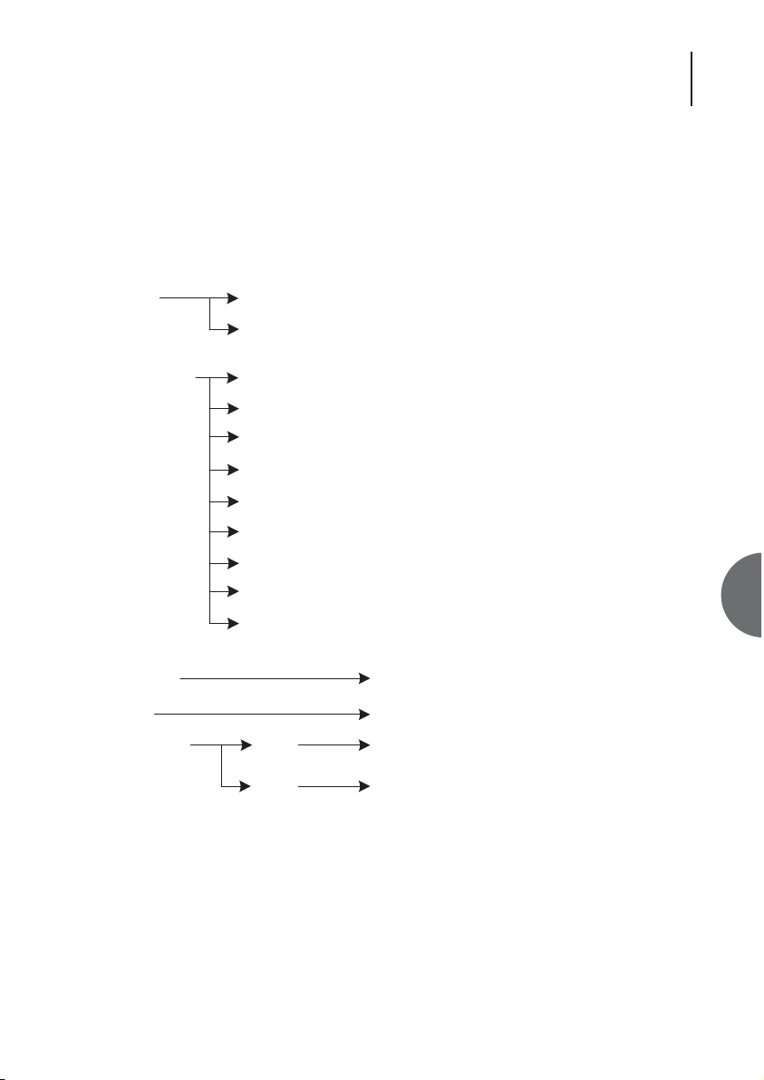
6.4 MENU STRUCTURE
The following table shows the top level and sub level menu structures. The proceeding pages will
explain the operation of each option.
s.
.
ke
Top Level
Alarms Status
Configuration Master/Slave
Logout
Sub level Description
History
User Port
DS0 Selection
Reboot
System
Subsystem Names
Monitoring
Serial Communications
Front Panel
Displays the current alarm status.
Review the fault log. View recorded alarm event
Master / slave configuration
Configure User Port
Timeslot selection for G703
Allows you to reboot the system
Set date, time and menu timeout
Enter name, description and location of this unit
Configures monitoring mode
Terminal set-up - baud rate, parity and handsha
Allows configuration of Front Panel controls
Displays the designation of the unit.Information
Logout of the menus and enter the monitoring
mode
Performance & Status of the optical lines.Performance Optical
Userport Performance & Status of the user interface
Page 30

ATL User Guide
OM25 OOptical MModem
30
6.5 ALARMS
6.5.1 ALARM STATUS SCREEN
F5 Clear
To remove an alarm from the list. Use the cursors to highlight it. Then press F5 to clear the line.
Only inactive alarms (marked ‘OFF’) can be removed from the list.
F6 Acknowledge
To acknowledge an alarm. Use the cursors to highlight it. Press F6 to acknowledge the alarm. To
clear the acknowledgement, fix the fault then clear (F5) the alarm.
Alarms Status
History
OM25 Fri 02 Jan 1970 01:24:51
Alarm > Status
Urgent Alarm:On Non-Urgent Alarm:Off
Display Filters: Level 1 [ ] 2 [X] 3 [X] 4 [X] 5 [X] Status=Off/Update [X]
No.| Subsystem | Alarm Description | Level | Status |A
001|Slave |Optical Port 0 - LOS | 1 | On |
002|Slave |Optical Port 0 - Loss Of Synch | 1 | On |
| | | | |
| | | | |
| | | | |
| | | | |
| | | | |
| | | | |
| | | | |
| | | | |
Press Escape to Exit
F1 Help F2 History F3 Previous Menu F4 Main Menu F5 Clear
F6 Acknowledge F7 Previous Page F8 Next Page F10 Update
Displays the current alarm status.
Review the fault log. View recorded alarm events.
Page 31
31
ATL User Guide
OM25 OOptical MModem
6
F10 Update
This screen is set to automatically update by default. However if the Status = Off/Update field has
been set to off, it may be necessary to update this screen manually by pressing F10.
Display Filters: Level 1 [ ] 2 [ ] 3 [ ] 4 [X] 5 [X]
If many alarms are active the user may wish to concentrate on investigating the higher priority
alarms first. To show alarms, select the appropriate display filter boxes with ‘X’, however, hidden
alarms will still generate Urgent and Non-urgent alarms.
Status = Off/Update [X]
To turn off automatic updates of this screen. Use the cursors to select the Status = Off/Update [X]
field. Pressing the space bar toggles the setting. The screen will not update until manually
refreshed – press F10 to manually update.
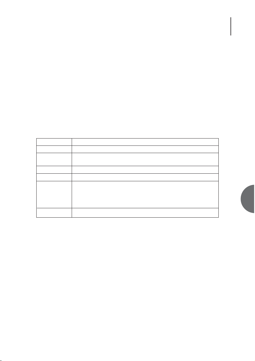
Field
No.
Subsystem
Alarm description
Level
Status
A
Description
Each entry is given a number.
Identifies which unit the alarm occurred on. The name is configured in the
Configuration->Subsystem name screen.
A description of the alarm
Shows the alarm severity.
ON = alarm currently active.
OFF = Transient alarm. Alarm is currently inactive, but has previously
been active.
Press F5 to clear.
Indicates that the alarm has been acknowledged, this mutes the alarm source.
Page 32

ATL User Guide
OM25 OOptical MModem
32
6.5.2 ALARM HISTORY SCREEN
This screen is used to view the last 15 alarms recorded by the system. If there is more than one
screen's worth of information, the up and down arrow keys may be used to scroll through the list.
The Master will report all of its alarms and those of its connected Slave unit.
To scroll between check boxes, use the left and right cursor keys.
To scroll between the alarm entries, use the up and down cursor keys.
F2 Show Id/Name
Toggles the ‘subsystem’ display field between name and ID.
F5 Clear History
Removes ALL entries from the fault log.
Alarms Status
History
OM25 Thu 01 Jan 1970 00:02:45
Alarm > History
Urgent Alarm:On Non-Urgent Alarm:Off
Display Acknowledged Faults [X] Subsystem [ ]
No.| Subsystem | Fault Description | Time | Date |A
001|Master |Cold Boot |00:00:01|01/01/1970|
002|Master |Optical Port 0 - LOS ON|00:00:03|01/01/1970|
003|Master |Optical Port 0 - Loss Of Synch ON|00:00:03|01/01/1970|
| | | | |
| | | | |
| | | | |
| | | | |
| | | | |
| | | | |
| | | | |
Press Escape to Exit
F1 Help F2 Show Id/Name F3 Previous Menu F4 Main Menu F5 Clear History
F7 Previous Page F8 Next Page F9 Dump F10 Update
Displays the current alarm status.
Review the fault log. View recorded alarm events.
Page 33
33
ATL User Guide
OM25 OOptical MModem
6
F9 Dump
Produces a continual listing of the fault log. Useful when capturing to a file.
F10 Update
The screen is not updated in real time. Events that occur after first entering the screen are not
displayed. To manually update the screen with recent events, press F10.
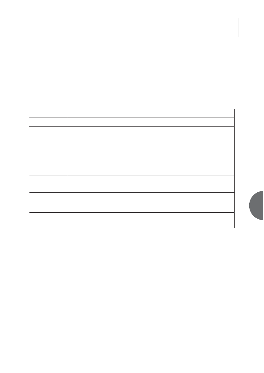
Field
No.
Subsystem
Fault description
Time
Date
A
Display Ack'd.
Faults [X]
Subsystem [ ]
Description
Each entry is given a number.
Identifies which unit the alarm occurred on. The name is configured in the
Configuration->Subsystem name screen.
A description of the alarm.
The 'ON' suffix indicates the recorded time and date the alarm went active.
OFF indicates when the alarm became inactive.
Records the exact time the event occurred.
Records the date the event occurred.
Indicated that the alarm has been acknowledged, this mutes the alarm source.
This checkbox controls the display of alarms that have been acknowledged in
the Alarm Screen. An 'A' in the 'A' (acknowledge) column indicates
acknowledged alarms.
This checkbox enables the display of only those events on the same subsystem
as the currently highlighted alarm entry.
Page 34

ATL User Guide
OM25 OOptical MModem
34
6.6 CONFIGURATION
6.6.1 MASTER/SLAVE CONFIGURATION
The OM25 unit default setting is as a slave.
In order for a pair of units to operate correctly, one end must be set as a master, the other end as
a slave. Normally the unit connected to the customer will be configured as a slave.
l
ke
Configuration Master/Slave
User Port
Reboot
System
Subsystem Names
Monitoring
Serial Communications
Front Panel
OM25 Thu 01 Jan 1970 00:00:43
Urgent Alarm:On Non-Urgent Alarm:On
Configuration > System Operation
Management Mode
Master ( )
Slave (* )
Independant ( )
DSL Gender
Co (*)
Cpe ( )
Master / slave configuration
Configure User Port
Allows you to reboot the system
Set date, time and menu timeout
Enter name, description and location of this unit.
Configures monitoring mode
Terminal set-up - baud rate, parity and handsha
Allows configuration of Front Panel controls
Manangement Mode changes will cause unit to reboot
F1 Help F3 Previous Menu F4 Main Menu
Page 35

35
ATL User Guide
OM25 OOptical MModem
6
The master unit is in charge of managing the optical link, it is also the 'master' from a network
management point of view. It contains the database of configuration information for itself and the
slave unit. The alarm and performance monitoring history is saved at the master.
When the management terminal is connected to the master it can read all of the information from
the local and remote units, whereas when the management terminal is connected to the slave,
only the local information is obtainable.
CO & CPE are also set on this screen.
Independent Mode - Requires both ends to be set up independently with compatible settings for
the desired data rate. Neither end configures the other in this mode.
Page 36
ATL User Guide
OM25 OOptical MModem
36
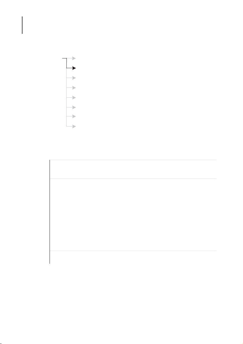
6.6.2 USER PORT CONFIGURATION
6.6.2.1 V35 USER PORT
Data Rate: The data rate can only be set by the ‘master’ unit and is set in increments of 64kbps.
The data rate is set by entering the desired value of N from 1 (64kbps) to 36 (2304kbps). The
default value of N is 32.
Timing Options: The timing options can only be set by the ‘master’ unit.
ke
Configuration Master/Slave
OM25 Thu 01 Jan 1970
Configuration > User Port
Urgent Alarm:On Non-Urgent Alarm:Off
Subsystem: Master
Port Type: OM25-V35
Rate (nx64): <32> Enable Loops:
Timing Control Lines:
Internal: (*) 106 Clamp On:
External: ( ) 107 Clamp On:
Loop: ( ) 109 Clamp On:
End-to-end Signalling
Press Return to Accept or Escape to Cancel
F1 Help F3 Previous Menu F4 Main Menu F7 Previous Subsystem
F8 Next Subsystem
User Port
Reboot
System
Subsystem Names
Monitoring
Serial Communications
Front Panel
Master / slave configuration
Configure User Port
Allows you to reboot the system
Set date, time and menu timeout
Enter name, description and location of this unit.
Configures monitoring mode
Terminal set-up - baud rate, parity and handsha
Allows configuration of Front Panel controls
Page 37

37
ATL User Guide
OM25 OOptical MModem
6
6.6.2.2 G703 USER PORT
All options can only be set by the ‘master’ unit.
OM25 Thu 01 Jan 1970 00:01:15
Configuration > User Port
Urgent Alarm:On Non-Urgent Alarm:On
Subsystem: Master
Unit Type: OM25-G703 75 Ohm
Timing Framing: TS0 Control
Through: (*) E1Unframed: (*) Regenerated: (*)
Local: ( ) E1: ( ) Inverted: ( )
Loop: ( ) E1Crc: ( )
E1Mf: ( ) Channelisation
E1CrcMf: ( ) Disabled: ( )
Enable DS0: (*)
Press Return to Accept or Escape to Cancel
F1 Help F2 Change Port Type F3 Previous Menu F4 Main Menu
F7 Previous Subsystem F8 Next Subsystem
Page 38

ATL User Guide
OM25 OOptical MModem
38
6.6.3 REBOOT
To reboot the unit press the space bar to select the local option and the the return key to activate
the reboot.
ke
Configuration Master/Slave
User Port
Reboot
System
Subsystem Names
Monitoring
Serial Communications
Front Panel
OM25 Thu 01 Jan 1970 00:02:30
Config > Reboot
Urgent Alarm:On Non-Urgent Alarm:Off
Local: [ ]
Press Return to Accept or Escape to Cancel
F1 Help F3 Previous Menu F4 Main Menu Use TAB to select fields
Master / slave configuration
Configure User Port
Allows you to reboot the system
Set date, time and menu timeout
Enter name, description and location of this unit.
Configures monitoring mode
Terminal set-up - baud rate, parity and handsha
Allows configuration of Front Panel controls
Page 39
39
ATL User Guide
OM25 OOptical MModem
6
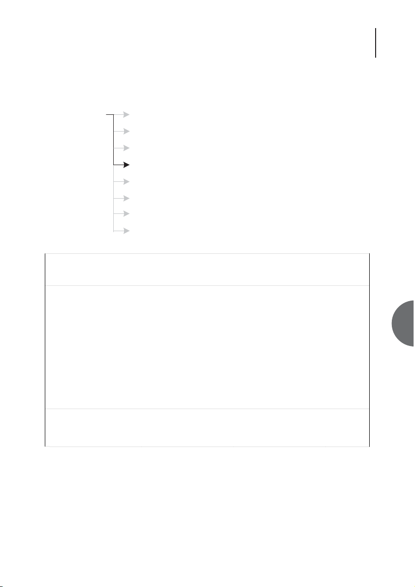
6.6.4 SYSTEM
This section allows the user to set the current date and time. The inactive time out setting can also
be set. Use the arrow keys or the tab key to navigate to required option. Once you have made the
required changes use the return key to accept the changes or use the escape key to cancel any
changes
ke
Configuration Master/Slave
User Port
Reboot
System
Subsystem Names
Monitoring
Serial Communications
Front Panel
Master / slave configuration
Configure User Port
Allows you to reboot the system
Set date, time and menu timeout
Enter name, description and location of this unit.
Configures monitoring mode
Terminal set-up - baud rate, parity and handsha
Allows configuration of Front Panel controls
OM25 Thu 01 Jan 1970 00:28:19
Configuration > System
Urgent Alarm:On Non-Urgent Alarm:Off
Date <01/01/1970>
Time (24Hr) <00:28>
Inactive Time-Out (min) <30>
Press Return to Accept or Escape to Cancel
F1 Help F3 Previous Menu F4 Main Menu
Page 40

ATL User Guide
OM25 OOptical MModem
40
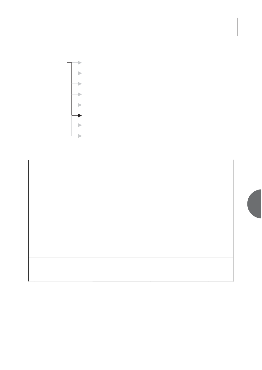
6.6.5 SUBSYSTEM NAMES
This section allows the user to set the name, description and location of the unit. Use the arrow
keys or the tab key to navigate to required option. Once you have made the required changes use
the return key to accept the changes or use the escape key to cancel any changes
ke
Configuration Master/Slave
User Port
Reboot
System
Subsystem Names
Monitoring
Serial Communications
Front Panel
OM25 Thu 01 Jan 1970 00:32:16
Configuration > Subsystem Names
Urgent Alarm:On Non-Urgent Alarm:Off
Subsystem No: 1
Name <Slave >
Description <Unknown >
Location <Unknown >
Press Return to Accept or Escape to Cancel
F1 Help F3 Previous Menu F4 Main Menu
Master / slave configuration
Configure User Port
Allows you to reboot the system
Set date, time and menu timeout
Enter name, description and location of this unit.
Configures monitoring mode
Terminal set-up - baud rate, parity and handsha
Allows configuration of Front Panel controls
Page 41
41
ATL User Guide
OM25 OOptical MModem
6
6.6.6 MONITORING
This screen is concerned with the monitoring mode of the master or slave units. This facility causes
system faults to be reported to a dumb terminal or printer whilst the operator is logged out.
Monitoring mode is a special mode that can operate when the user has logged off. It is designed
to connect to a printer or an unattended terminal. As alarms and faults are detected they are
printed on the screen (one line per fault). Over time a complete list of faults will be seen.
ke
Configuration Master/Slave
User Port
Reboot
System
Subsystem Names
Monitoring
Serial Communications
Front Panel
Master / slave configuration
Configure User Port
Allows you to reboot the system
Set date, time and menu timeout
Enter name, description and location of this unit.
Configures monitoring mode
Terminal set-up - baud rate, parity and handsha
Allows configuration of Front Panel controls
OM25 Thu 01 Jan 1970 00:52:52
Configuration > Monitoring
Urgent Alarm:On Non-Urgent Alarm:Off
Monitoring Mode
Report Faults [ ]
With Warning Bell [ ]
Press Return to Accept or Escape to Cancel
F1 Help F3 Previous Menu F4 Main Menu
Page 42

ATL User Guide
OM25 OOptical MModem
42
Should the VT100 terminal remain connected whilst logged out, and provided that certain options
(in the Configuration > Monitoring Screen) have been set, warning messages indicating alarm
conditions will be displayed. These warning messages may be accompanied by an audible beep.
The VT100 terminal may at this point be replaced by a printer with a serial interface, allowing hard
copy of all alarms to be obtained.
It is envisaged that a dumb terminal may be left continuously connected to the master or slave
after the operator has logged out. This mode may then be used to register the indication of alarms
externally. The dumb terminal may be used to report alarm situations. These external indications
would consist of warning messages and/or alarm bells.
Format of warnings displayed in Monitor Mode is as follows:
Master:F4:Line - Loss of Recovered Clock ON:Thu 01 Jan 2002 00:27:57
Slave:F5:User Port - Input Signal Loss OFF:Thud 01 Jan 2002 00:27:59
The format should match that used to display the fault in the VTMS Menu System status line.
Note: The fault log can also be viewed and printed from the Alarms->History menu - as shown in
section 6.5.2.
Page 43
43
ATL User Guide
OM25 OOptical MModem
6
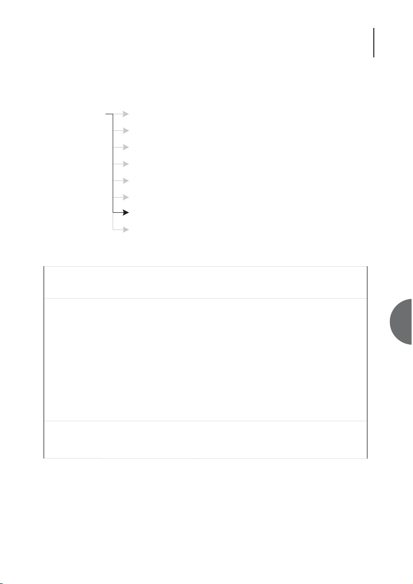
6.6.7 SERIAL COMMUNICATIONS
ke
Configuration Master/Slave
User Port
Reboot
System
Subsystem Names
Monitoring
Serial Communications
Front Panel
OM25 Thu 01 Jan 1970 02:10:15
Configuration > Serial Communications
Urgent Alarm:On Non-Urgent Alarm:Off
Baud Rate Data Bits Parity Stop Bits Handshake
2400 ( ) 7 ( ) None (*) 1 None ( )
4800 ( ) 8 (*) Odd ( ) Xon/Xoff (*)
9600 ( ) Even ( )
19200 (*)
Press Return to Accept or Escape to Cancel
F1 Help F3 Previous Menu F4 Main Menu F5 Default
Master / slave configuration
Configure User Port
Allows you to reboot the system
Set date, time and menu timeout
Enter name, description and location of this unit.
Configures monitoring mode
Terminal set-up - baud rate, parity and handsha
Allows configuration of Front Panel controls
Page 44

ATL User Guide
OM25 OOptical MModem
44
6.6.7.1 PROCEDURE TO FOLLOW WHEN CHANGING SETTINGS
1.Make all the desired changes to this menu by using the cursor to move to the appropriate check
box, then press the space bar to change the selected field.
2.Once all the desired changes have been made, press the <return> key to accept the changes.
The unit will now implement these changes.
3.A message will appear: “Change your terminal to new settings.... Press Escape to continue”.
4.Referring to the user manual for your terminal – change its communications set-up in the same
way you changed this menu.
5.Press the <Escape> key.
Notes:
a) The OM25 tries to change baud rates smoothly. However if the new screen is not displayed
correctly you may have to reset your local terminal.
b) If the characters still appear corrupt then choose a lower baud rate.
Field
Baud rate
Data bits
Parity
Stop bits
Handshake
Description
Speed at which characters are sent and received from the local terminal.
Higher numbers mean faster speed. If characters are being corrupted try a
lower speed.
Some terminals require 7 bit data if parity is turned on. Most prefer 8 bit data.
Provides a means of checking characters for errors (but does not correct them).
1 stop bit is standard.
Turning this on allows your local terminal to control the rate at which
characters are being sent.
This is useful if your terminal cannot keep up with the rate at which characters
are produced.
Note: if characters are being corrupted, turning on handshaking will not help –
choose a slower baud rate instead.
Page 45
45
ATL User Guide
OM25 OOptical MModem
6
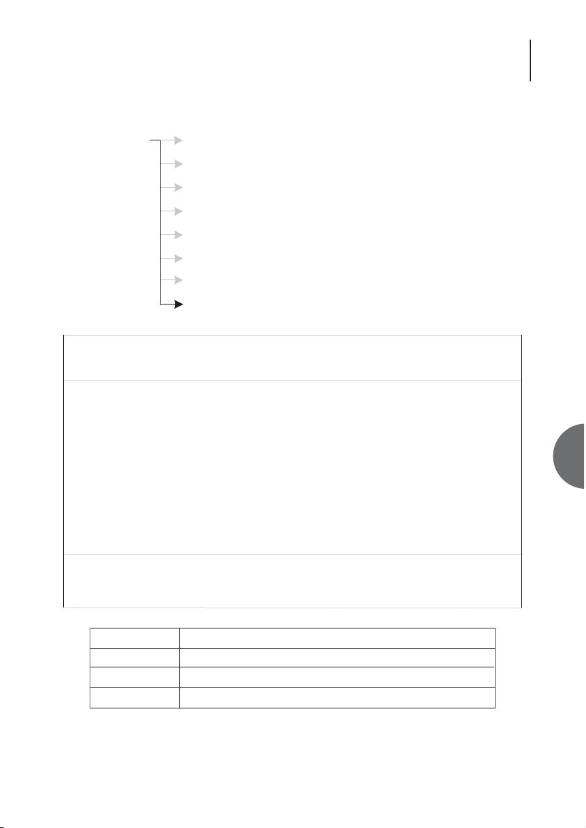
6.6.8 FRONT PANEL
ke
Configuration Master/Slave
User Port
Reboot
System
Subsystem Names
Monitoring
Serial Communications
Front Panel
OM25 Thu 01 Jan 1970 02:13:22
Configuration > Front Panel
Urgent Alarm:On Non-Urgent Alarm:Off
Subsystem: Slave
Front Panel Buttons:
Full Control (*)
Loops Only ( )
Disabled ( )
Press Return to Accept or Escape to Cancel
F1 Help F3 Previous Menu F4 Main Menu
Master / slave configuration
Configure User Port
Allows you to reboot the system
Set date, time and menu timeout
Enter name, description and location of this unit.
Configures monitoring mode
Terminal set-up - baud rate, parity and handsha
Allows configuration of Front Panel controls
Field Description
Full Control Front panel buttons may be used for testing loops, and unit configuration
Loops Only Buttons can be used for testing loops, but not for unit configuration
Disabled Buttons are disabled
Page 46
ATL User Guide
OM25 OOptical MModem
46
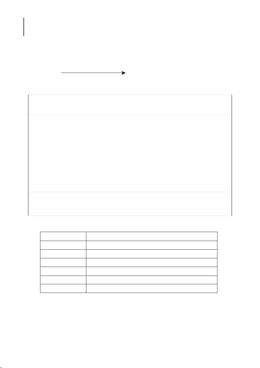
6.7 INFORMATION
Please quote these figures when contacting our technical support department.
Displays the designation of the unit.Information
OM25 Thu 01 Jan 1970 02:42:19
Information
Urgent Alarm:On Non-Urgent Alarm:Off
Subsystem: Slave
Unit Type: OM25-V35
Hardware Id: Issue A
Mod Status: Mod 4
Booter Version: 0.0a 2004 04 05 AM29LV800T Boot
Software Version: 0.0h%2004 04 08 OM25
Firmware Version: 1.00 2004 04 07 Iss 128
Press Escape to Exit
F1 Help F3 Previous Menu F4 Main Menu
Field Description
Unit type Displays the unit's product name and type.
Hardware Id Indicates the build number for the hardware platform
Mod Status Relates to the modification status of the unit
Software version Displays the version number for the software being run
Booter version Displays the version number for the boot-strap loader
Firmware version Displays the version number for the firmware
Page 47
47
ATL User Guide
OM25 OOptical MModem
6
6.8 PERFORMANCE
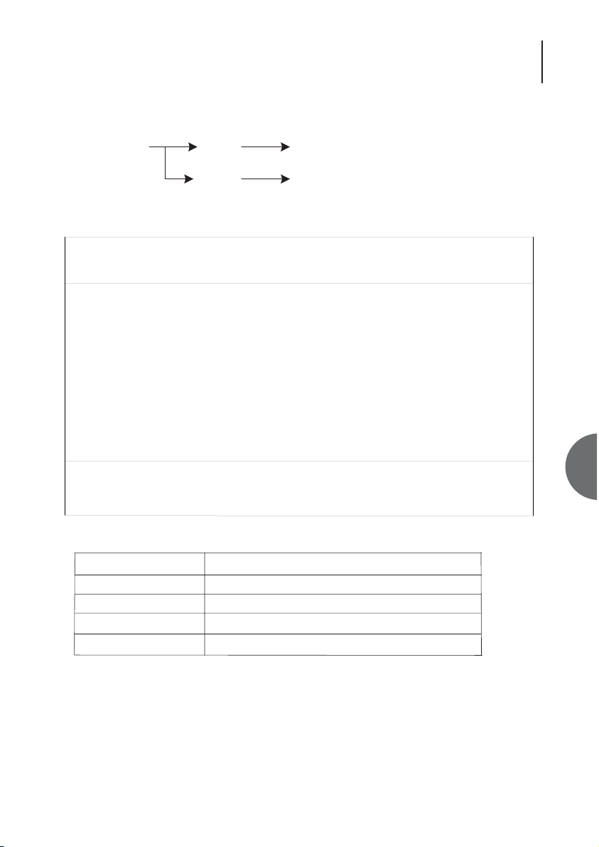
6.8.1 PERFORMANCE OPTICAL LINES
Performance & Status of the optical lines.Performance Optical
UserPort
Performance & Status of the user port.
OM25 Thu 01 Jan 1970 00:03:33x
Performance > Optical
Urgent Alarm:On Non-Urgent Alarm:On
Subsystem: Slave View: Local Statistics
Table | ES | SES | UAS | BBE | Time Elapsed
Current | 0 | 0 | 212 | 0 | 212
Total | 0 | 0 | 0 | 0 |
Interval | ES | SES | UAS | BBE | Valid
1 | 0 | 0 | 0 | 0 | No
2 | 0 | 0 | 0 | 0 | No
3 | 0 | 0 | 0 | 0 | No
4 | 0 | 0 | 0 | 0 | No
5 | 0 | 0 | 0 | 0 | No
6 | 0 | 0 | 0 | 0 | No
Press Escape to Exit
F1 Help F2 View F3 Previous Menu F4 Main Menu F5 Next Interface
F6 Previous Interface F9 Next Intervals F10 Previous Intervals
Field Description
UAS Unavailable seconds Total time this optical link has been out of service
SES Severely errored seconds Total time this optical link has suffered heavy errors
ES Errored seconds Total time this optical link has suffered light errors
BBE Background Block Errors CRC errors when no SES have occured
Page 48

ATL User Guide
OM25 OOptical MModem
48
6.8.2 PERFORMANCE USER PORT
OM25 Thu 01 Jan 1970 00:26:33
Performance > USER
Urgent Alarm:On Non-Urgent Alarm:On
Subsystem: Slave View: Local Statistics
Table | ES | SES | UAS | SEFS | LES | Time Elapsed
Current | 0 | 0 | 1592 | 0 | 0 | 1592
Total | 0 | 0 | 0 | 0 | 0 |
Interval | ES | SES | UAS | SEFS | LES | Valid
1 | 0 | 0 | 0 | 0 | 0 | No
2 | 0 | 0 | 0 | 0 | 0 | No
3 | 0 | 0 | 0 | 0 | 0 | No
4 | 0 | 0 | 0 | 0 | 0 | No
5 | 0 | 0 | 0 | 0 | 0 | No
6 | 0 | 0 | 0 | 0 | 0 | No
Press Escape to Exit
F1 Help F2 View F3 Previous Menu F4 Main Menu F5 Next Interface
F6 Previous Interface F9 Next Intervals F10 Previous Intervals
Field Description
UAS Unavailable seconds Total time this optical link has been out of service
SES Severely errored seconds Total time this optical link has suffered heavy errors
ES Errored seconds Total time this optical link has suffered light errors
SEFS Severely errored framing seconds Total time this optical link has suffered from framing errors
LES Line errored seconds Total line errored seconds
Page 49
49
ATL User Guide
OM25 OOptical MModem
6
6.9 SECURITY
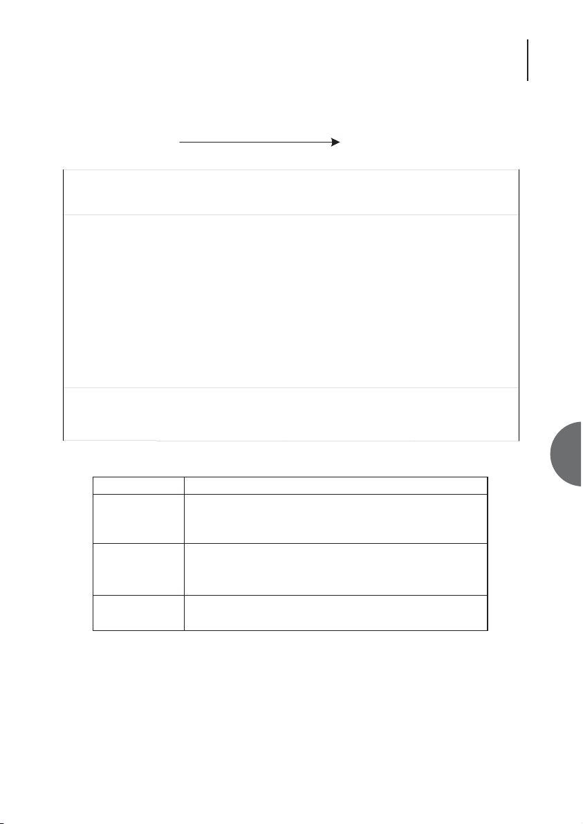
This section deals with the security of the system. Access to the OM25 is password protected. All
password characters are displayed as asterisks (*), with <RETURN> as the default password.
FORGOTTEN YOUR PASSWORD
Fax Atl Telecom technical support on: ++44 2920 500 850
or send an e-mail to: [email protected]
Change passwordsSecurity
OM25 Thu 01 Jan 1970 05:00:56
Security > System
Urgent Alarm:On Non-Urgent Alarm:Off
Old Password [ ]
New Password [ ]
Confirm Password [ ]
Press Return to Accept or Escape to Cancell
F1 Help F3 Previous Menu F4 Main Menu
Field
Old Password
Function
This field accepts the password currently attributed to the
system. When the password is recognised (on entry of the
final password character) the password field is enabled.
New Password
This field always displays its contents as asterisks, and has a
maximum length of 10 characters.
This field defaults to null after initial power on
Confirm Password
This field is enabled when the operator enters text into the
password field
Page 50

ATL User Guide
OM25 OOptical MModem
50
6.10 TEST
Test Options
Local Loop - Loops the traffic back to the user interface
Loopback - Loops the traffic back to the optical line
V.54 Remote Loop - Sets a loopback on the remote unit.
Enables various loopsTest
OM25 Thu 01 Jan 1970 05:22:45
Test > Loopbacks
Urgent Alarm:On Non-Urgent Alarm:Off
Subsystem: Slave
Local Loop : [ ]
Loopback : [ ]
V54 Remote Loop: [ ]
Press Return to Accept or Escape to Cancel
F1 Help F3 Previous Menu F4 Main Menu
Page 51
51
ATL User Guide
OM25 OOptical MModem
7
7. CONFIGURATION VIA THE FRONT PANEL BUTTONS
7.1 INTRODUCTION
For users that prefer to configure the OM25 without the need of a PC, the operating parameters
can be configured using the front panel controls.
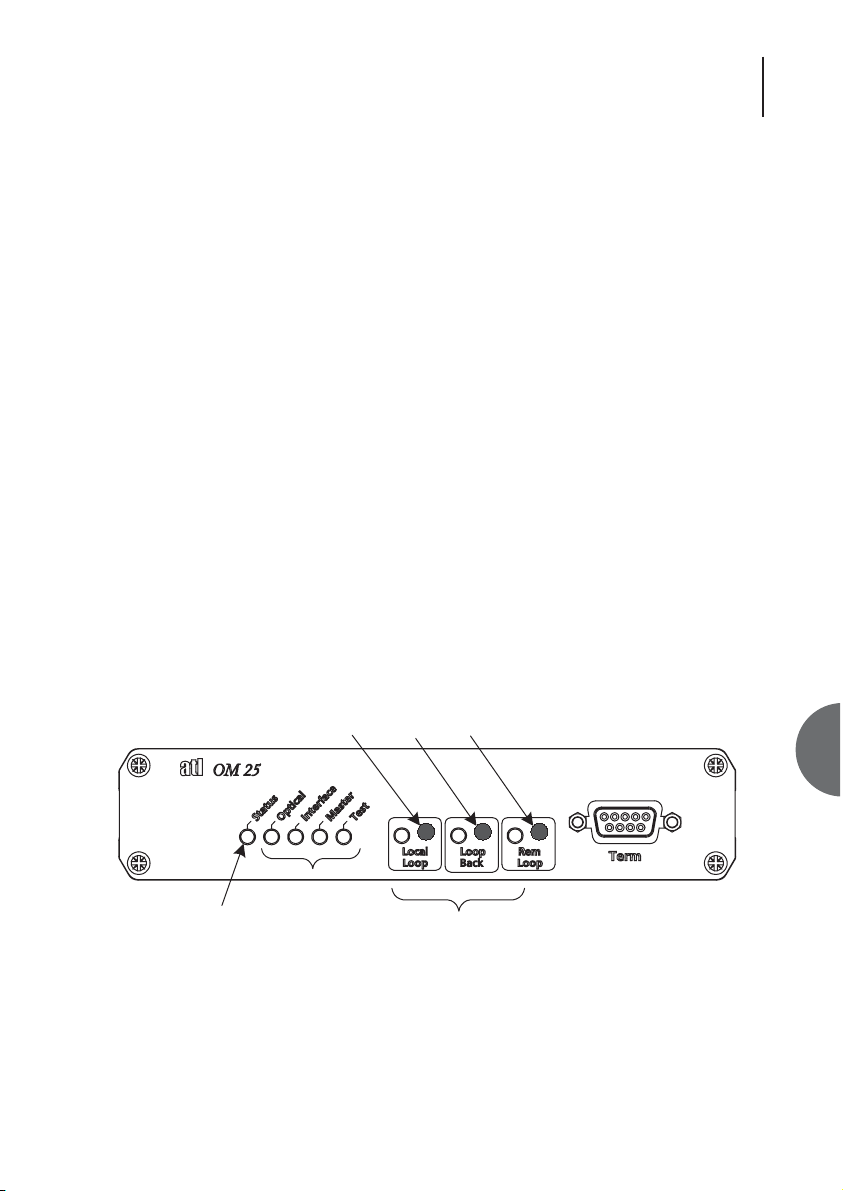
Front panel programming is carried out by placing the unit into Programming Mode by pressing
the "Local Loop" and Loop Back" buttons simultaneously and then releasing them. Programming
mode will be indicated by the Status LED flashing Amber. The Local Loop, Loop Back and Remote
LED indicators will display the parameter being configured.The Optical, Interface, Master and Test
LED indicators will display the parameter value. Sections 7.2.1 to 7.2.3 show the full lists of
parameters and their corresponding values that can be programmed.
Note: If the front panel controls have been previously set to "Loops only" or "Input disabled" from
the VT100 Front Panel configuration screen, it will not be possible to enter Programming Mode.
7.2 OPERATION
The "Local Loop" button is used to change the “Parameter Number”. The “Loop Back” button is
used to change the “Parameter Value”. Once programming is completed, the "Remote Loop"
button is pressed to store the new parameter value (this must be done within 30 seconds of the
last programming action or the modem will automatically leave programming mode and discard
the new values). When "Remote Loop" is pressed, the modem reboots into its new configuration.
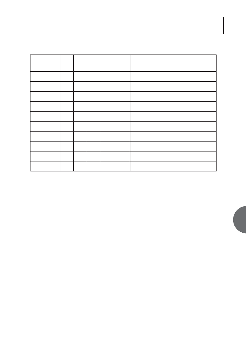
All of the configurable parameters have a "Parameter Number" displayed as a 3-bit binary number
on the loop active indicators (Local Loop = MSB). The “Parameter Values” that can be selected are
displayed as a 4 bit binary number on the Optical, Interface, Master and Test indicators (Optical =
MSB).
51
Flashing = Programming
Next
Parameter
Value
Parameter
Next
Value
Save
Changes
Number
Parameter
Page 52

ATL User Guide
OM25 OOptical MModem
52
7.2.1 GENERAL
Parameter
Number
1
2
7 Normal Operation
LL
0
0
LB
0
1
RL
1
0
111
Parameter
Value
0000
0001
0010 Master CPE
0000
0001
0010
0011
0100
0101
0110
0111
1000
1111
0000
0001
Slave (Default)
Master CO
User Port Rate 1 (n=1, 64kbps)
User Port Rate 2 (n=2, 128kbps)
User Port Rate 3 (n=4, 256kbps)
User Port Rate 4 (n=8, 512kbps)
User Port Rate 5 (n=10, 640kbps)
User Port Rate 6 (n=12, 768kbps)
User Port Rate 7 (n=16, 1024kbps)
User Port Rate 8 (n=32, 2048kbps)
User Port Rate 9 (n=36, 2304kbps)
Rate not selectable via Front Panel
Set Default Operation (value
returns to 0000 after saving)
Meaning
Page 53
53
ATL User Guide
OM25 OOptical MModem
7
7.2.2 G.703 OPTIONS
Parameter
Number
3
4
5 Regenerate TS0
LL
LB
1
0
0
1
RL
1
0
101
Parameter
Value
0000
0001
0010
0000
0001
0010
0011
0100
0000
0001
Timing Through
Timing Local
Timing Loop
Unframed
E1, CRC disabled
E1, CRC enabled
E1 CAS, CRC disabled
E1 CAS, CRC enabled
Invert TS0
Meaning
Page 54

ATL User Guide
OM25 OOptical MModem
54
7.2.3 V.35 OPTIONS
7.3 KEYPAD LOCK
Pressing the Local Loop, Loop Back and the Remote Loop buttons simultaneously for a minimum
of 5 seconds will lock the front panel buttons. The Loop LEDs will flash amber during this period.
Repeating this action will unlock the buttons again.
7.4 AUXILIARY PORT OPERATION
Pressing the Local Loop and Remote Loop buttons simultaneously for a minimum of 5 seconds (the
left most 3 LEDs flash amber) converts the Terminal Port into an Auxiliary Port which can be used
to transport an RS-232 link transparently across the fibre path, independently from the main data
payload. Repeating this action converts the port back to its management function (the 3 left most
LEDs flash red).
Parameter
Number
3
4
5
6
LL
LB
1
0
0
1
0
1
1
1
RL
1
0
1
0
Parameter
Value
0000
0001
0000
0001
0000
0001
0010
0011
0100
0101
0110
0111
0000
0001
0010
Meaning
Enable Loops (Default)
Disable Loops
End to End Signalling Off (Default)
End to End Signalling On
Clamp 106 Off, 107 Off, 109 Off
Clamp 106 Off, 107 Off, 109 On
Clamp 106 Off, 107 On, 109 Off
Clamp 106 Off, 107 On, 109 On
Clamp 106 On, 107 Off, 109 Off
Clamp 106 On, 107 Off, 109 On
Clamp 106 On, 107 On, 109 Off
Clamp 106 On, 107 On, 109 On (Def)
Timing Internal (default CO)
Timing External
Timing Loop (CPE)
Page 55

55
ATL User Guide
OM25 OOptical MModem
8
8. SPECIFICATIONS
8.1 DIMENSIONS
The overall dimensions of the unit are:
Height = 45mm
Width = 165mm
Depth = 185mm
8.2 TRANSMISSION PERFORMANCE
8.2.1 JITTER
To G.823
8.2.2 TRANSMISSION RANGE
The range achieved will depend upon to optical fibre used. The better the quality of fibre the
further the range achieved. Typical figures given below.
Loss budget - Long Haul = 31dB
Short Haul = 16dB
8.3 AC POWER INLET
AC power is fed via a standard 3-pin 250V 2.5A IEC/EN 60320-1/C6 socket. A power cord fitted
with a country specific mains plug is supplied with the unit. This should be plugged into a suitable
power supply with earth protection to provide ESD protection for the unit.
Page 56
ATL User Guide
OM25 OOptical MModem
56
8.4 DC POWER INLET
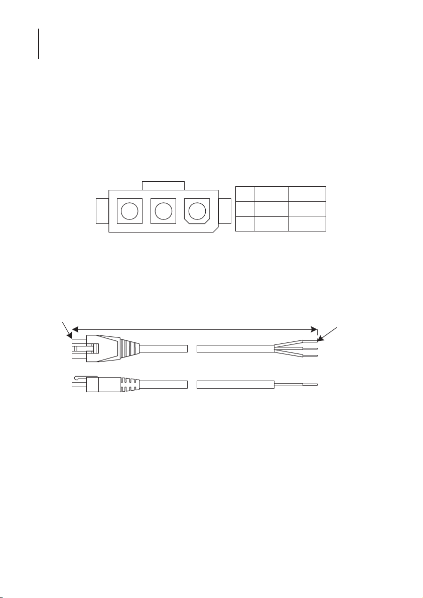
DC power is fed in via the three-pin socket on the rear panel. The cable assembly is shown in
section 8.5. A connection from CGND to earth is required for ESD protection of the unit.
Mating connector
Molex Minifit Junior Receptacle Molex Part Number: 39-01-4031
Molex female contact Molex Part Number: 39-00-0039
8.5 DC MAINS CABLE
The DC Power Cable can be ordered from ATL, ATL Part Number 6/910/000/423 (See
ACCESSORIES).
12-48V
2 13
3 CGND
0V
WHITE
RED
BLACK
Pin
1
3,000mm
Stripped &
Tinned
White
Red
Black
Page 57

57
ATL User Guide
OM25 OOptical MModem
8
8.6 OPTICAL CONNECTIONS
8.6.1 SAFETY WARNING
Class 1 laser product.
Exposure to the optical beam will not result in eye damage, however it is never advisable to look
into the optical port or fibre. The laser light is invisible and prolonged exposure should be avoided
as the human eye cannot respond to its presence.
8.6.2 OPTICAL CONNECTOR CLEANING
The vast majority of problems are caused by dust contamination of the optical window. Before
installing the optical plug, its end must be cleaned with an approved disposable optical wipe. The
optical connector on the unit must be cleaned by blowing clean (oil and dust free) compressed air
down the centre of the optical connector.
8.6.3 FC.PC CONNECTOR
This connector is more commonly used on single-mode cable. To connect – align the centre of the
fibre plug with the centre of the optical connector (on the rear panel). Push the plug in gently.
Rotate to align the keyway. The plug should now go in a little more. Make sure the keyway is
correctly located by rotating the plug to the left and to the right. Only a little movement should be
allowed. Once in place secure the plug by turning the locking ring clockwise. Taking care not to
over-tighten the locking ring – excessive pressure will cause misalignment, finger tight is more than
ample.
FC/PC Connector
Page 58
ATL User Guide
OM25 OOptical MModem
58
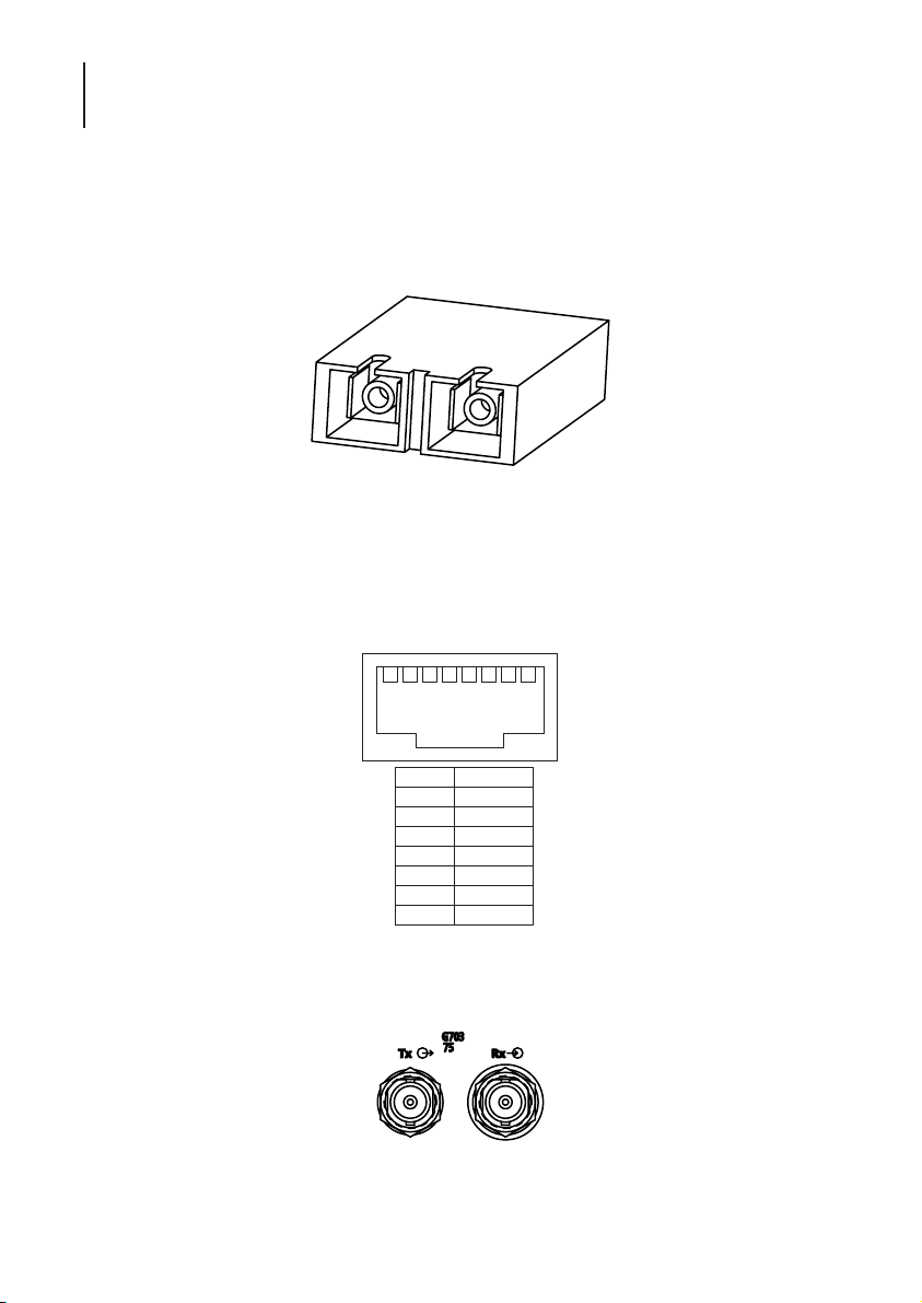
8.6.4 SC CONNECTOR
Align the key on the connector plug with the keyway in the top of the optical connector (on the
rear panel). Gently push the plug into the connector until an audible ‘click’ is heard.This type if
plug is fitted with an anti pull out feature, this prevents the accidental removal of the plug from
the connector.
SC Connector
8.7 INTERFACE CONNECTIONS
8.7.1 G.703 120 OHM INTERFACE
The G703 120 Ohm connector on the OM25 is an 8-way RJ45 socket
8.7.2 G.703 75 OHM INTERFACE
Two BNC connectors are used on the back of the unit to give the 75-ohm connection
21 3 4 5 6 7 8
1 TxA
2 TxB
3 screen
4 RxA
5 RxB
6 screen
7 n.c.
8 n.c.
Ω
Page 59
59
ATL User Guide
OM25 OOptical MModem
8
8.7.3 V.35 INTERFACE
A-wire
P
R
U
Y
V
Pin
B-wire
S
T
W
AA
X
Unbal
B
C
D
E
F
N
L
NN
Circuit
102
103
104
105
106
107
109
113
114
115
140
141
142
Description
Common Return
Transmit Data
Receive Data
Request To Send
Ready For Sending
Data Set Ready
Received Signal Detector
Terminal Signal Element Timing
Transmitter Signal Element Timing
Receiver Signal Selement Timing
Remote Loopback
Local Loopback
Test Indicator
Page 60

ATL User Guide
OM25 OOptical MModem
60
8.7.4 V.35 EXTERNAL TIMING ADAPTOR CABLE PINOUT
CCITT circuit Timing Source (DCE) Timing Sink (DTE) CCITT circuit
103-A P R 104-A
103-B S T 104-B
104-A R P 103-A
104-B T S 103-B
105 C F 109
109 F C 105
115-A V U 113-A
115-B X W 113-B
GND B B GND
Page 61
61
ATL User Guide
OM25 OOptical MModem
8
8.8 TERMINAL CONNECTION
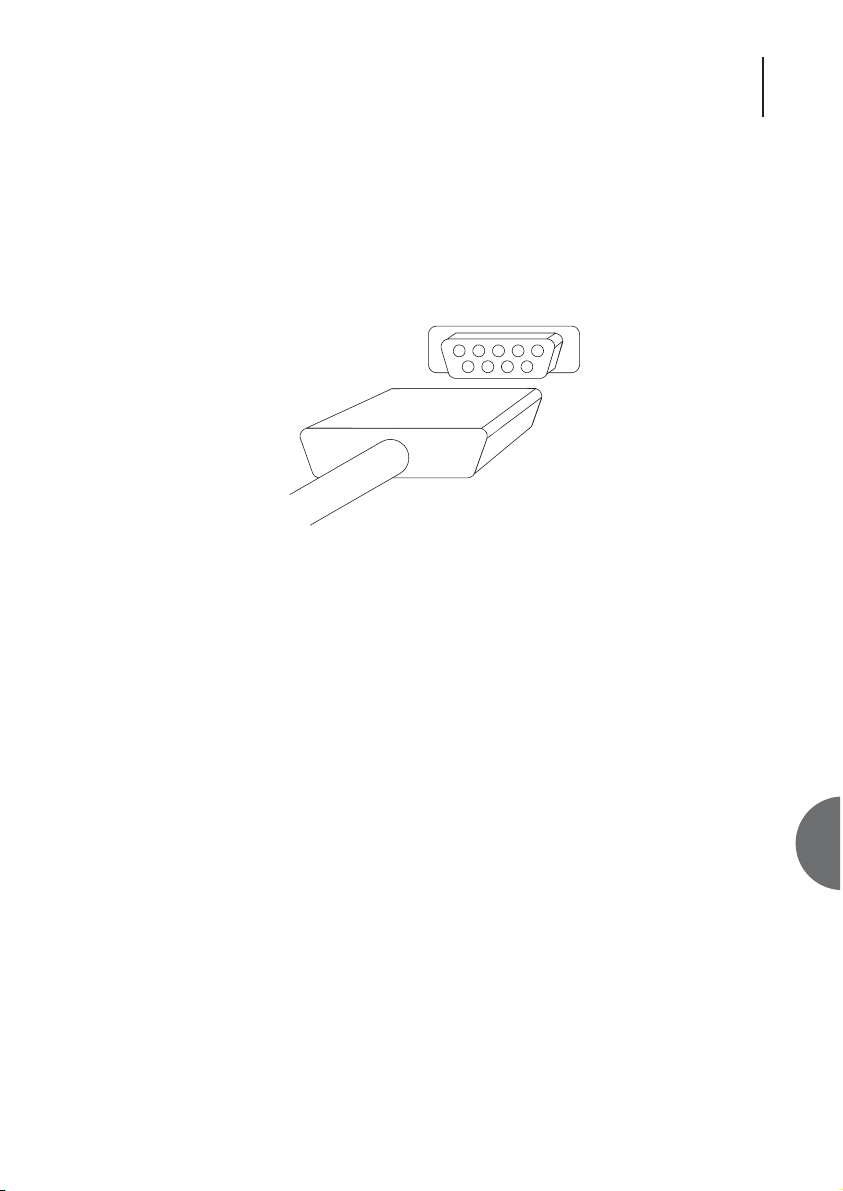
A VT100 compatible terminal can be plugged into the 9-way D-type connector on the front panel.
The socket is wired to allow a straight connection to a PC serial port.
The serial port setting is 19200 baud, 8 bits, no parity, 1 stop bit and Xon/Xoff flow control.
The RS232C interface complies with the CCITT V24/V28 standards. The maximum length of cable
between communicating devices is limited to 15.2 metres (50 feet).
Page 62

ATL User Guide
OM25 OOptical MModem
62
8.9 ENVIRONMENTAL
8.9.1 TRANSPORTATION
ETS 300 019-1-2 Class 2.3
Transportation using normal public transport when stored in its normal transport packaging.
Temp range -40 to +70°C
Humidity +5 to +95% (non condensing)
8.9.2 STORAGE
ETS 300 019-1-1 Class 1.1
Storage in a totally weatherproof and partially temperature controlled environment in its standard
packaging.
Temp range -5 to +45 OC
Humidity 95% @ 45 OC (non condensing)
8.9.3 OPERATIONAL
ETS 300 019-1-3 Class 3.2
Operation in a totally weatherproof and partially temperature controlled environment.
Temp range -0 to +45 OC
Humidity +5 to +90% (non condensing)
Page 63

63
ATL User Guide
OM25 OOptical MModem
9
9. ORDERING INFORMATION
9.1 OM25 AC POWERED
Description Order Number
OM25 Long Haul V.35 1/356/111
OM25 Long Haul G.703 75 ohms 1/356/112
OM25 Long Haul G.703 120 ohms 1/356/113
OM25 Short Haul V.35 1/356/211
OM25 Short Haul G.703 75 ohms 1/356/212
OM25 short Haul G.703 120 ohms 1/356/213
9.2 OM25 DC POWERED
Description Order Number
OM25 Long Haul V.35 1/356/121
OM25 Long Haul G.703 75 ohms 1/356/122
OM25 Long Haul G.703 120 ohms 1/356/123
OM25 Short Haul V.35 1/356/221
OM25 Short Haul G.703 75 ohms 1/356/222
OM25 short Haul G.703 120 ohms 1/356/223
9.3 ACCESSORIES
Description Order Number
OM25 DC Power Cable 6/910/000/423
OM25 AC UK Power Cable 6/910/000/531
OM25 AC Euro Power Cable 6/910/000/532
OM25 RS232 Cable 6/910/000/429
 Loading...