

Page 1

AM 100
USER GUIDE
24
ATL User Guide
AM100 MModem
9. ORDERING INFORMATION
9.1 AM100 DC POWERED
AM100 X21 1/372/X21
AM100 V35 1/372/X22
AM100 G703 1/372/X23
9.2 AM100 AC POWERED
AM100 X21 1/372/X11
AM100 V35 1/372/X12
AM100 G703 1/372/X13
9.3 MOUNTING BRACKET
The AM100 can be supplied either with or without a wall mounting brackets. This is a factory fitted
option.
Supplied with a wall brackets X = 1
supplied without a wall brackets X = 0
9.3 ACCESSORIES
X21 DCE STUB CABLE 6/910/000/534
V35 DCE STUB CABLE 6/691/000/533
G703 RJ45 STUB CABLE 6/910/000/544
Page 2
23
ATL User Guide
AM100 MModem
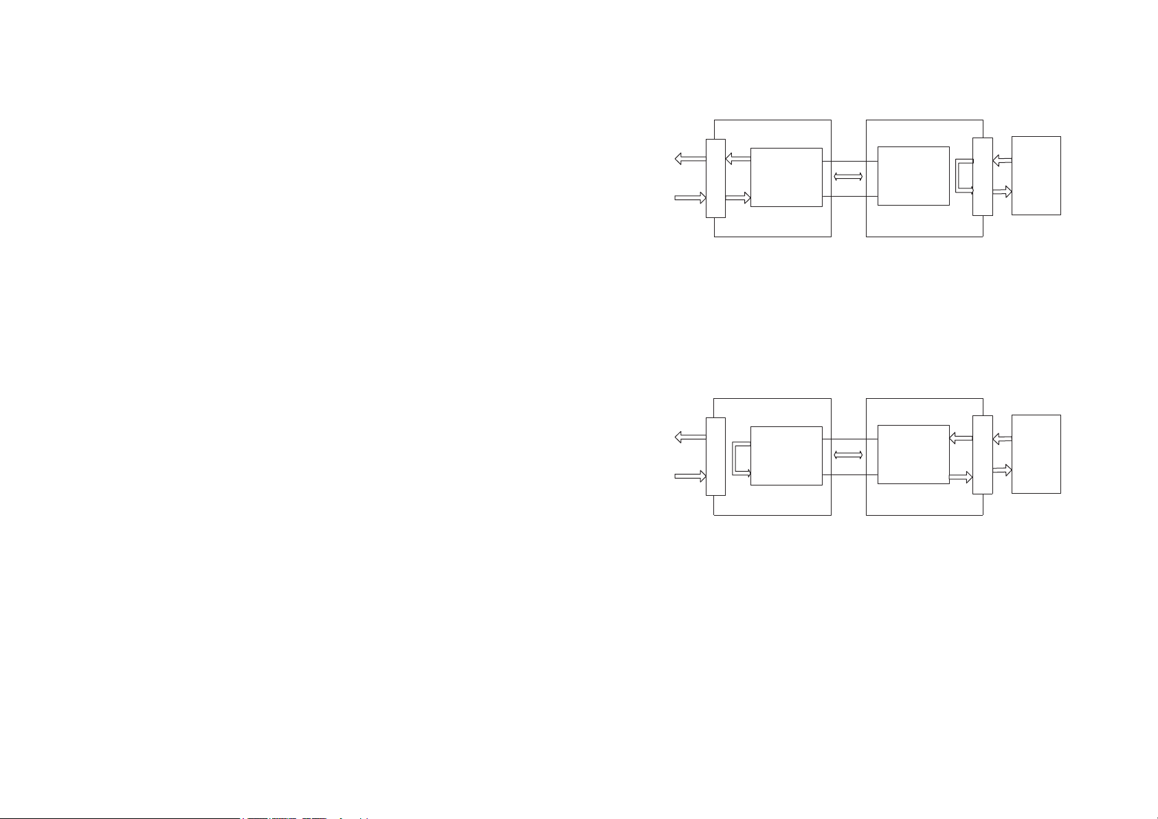
8.2.2 REMOTE LOOP
With a BERT still connected as above, turn off the local loop and apply the remote loop. The
remote loop loops data back to the user interface from the far end modem as shown below, thus
this test can be used to check the integrity of the line.
There should be no errors or a very low error rate. If the error rate received is too high for your
application, try a lower data rate. When you have completed this test, turn off remote loop.
8.2.3 FAR END LOCAL LOOP
If the two tests above have been performed then also perform test 8.2.1 (local loop) on the far end
modem.
8.2.4 LOOPBACK
Applying a Loopback on the local modem causes the received line data to be returned to the far
end modem.
Remote Modem Local Modem
Remote Modem Local Modem
ATL Part No 1/372/001/610
Issue: 01
Disclaimer
The information contained in this document is confidential to ATL Telecom Ltd. and may not be
disclosed or reproduced in whole or in part without their written consent.
© ATL Telecom Ltd 2004.
Note: The information contained in this document is supplied without liability for errors or
omissions.
ATL Telecom Limited reserves the right to make changes to this document at any time without
notice.
Transmission
System
Interface
Transmission
System
Interface
Transmission
System
Interface
local loop applied in this modem
Transmission
System
Interface
remote loop selected from this modemloop applied here
BERT
BERT
Page 3
3
ATL User Guide
AM100 MModem
COMPLIANCE NOTES & SAFETY INSTRUCTIONS
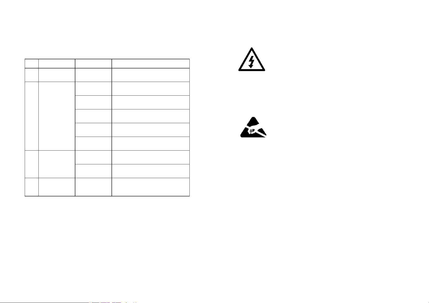
Caution: - Hazardous voltages inside the equipment
Safety Instructions:
This apparatus must be installed and maintained by SERVICE PERSONNEL only
There are NO user serviceable parts inside the modem.
The mains plug on the equipment serves as the disconnect device, therefore a socket outlet shall
be installed near the equipment and shall be easily accessible
Caution: - Electrostatic sensitive devices inside the equipment
Electrostatic discharge (ESD) Warning:
Antistatic precautions should be observed at all times.
Power Rating Information - AC unit:
Voltage Range 85V-250V
Current Range 50mA-15mA
Frequency Range 50/60Hz
Power Rating Information - DC Unit:
Voltage Range -18V to -72V
Current Range 170mA-25mA
Safety Statements classification - NON traffic ports
The AC Mains input has a safety status of PRIMARY CIRCUIT
The AM100 AC unit is defined as a class 1 equipment and must be connected to a reliable earth
connection.
If the mains earth cannot be guaranteed to be PROTECTIVE EARTH, then a PROTECTIVE EARTH
conductor must be connected to the M3 stud on the rear panel of the unit.
The DC input has a safety status of TNV-2
22
ATL User Guide
AM100 MModem
8. TROUBLE SHOOTING
8.1 QUICK GUIDE TO BASIC FAULT FINDING
8.2 LINK PERFORMANCE
The AM100 modem has a number of features to aid in the testing of the data link. To check a data
link the following tests can be performed. The tests outlined will require the use of a Bit Error Rate
Tester (BERT).
8.2.1 LOCAL LOOP
With a BERT connected to the user interface a local loop will loop data back to the user interface
as shown below. If everything is ok, no errors should be detected i.e. the user interface is correctly
transporting data.
No Symptom Possible Fault Corrective Action
Replace fuse in mains lead.LEDs do not light Blown fuse1
Configuration of
modems incorrect
Lines not correctly
connected.
Modems do not
2
synchronise with
3
high error rate
synchronise with
4
no data transfer
synchronise
Modems
Modems
Line attenuation
or noise too high
External timing
signal incorrect
Internal fault Return unit for repair
Line attenuation
or noise too high
External timing
signal incorrect
Test loop active
Check configuration
Check that line pair are correctly
connected together.
Select a lower data rate
Check external timing signal quality and
cable assembly. Check Configuration.
Select a lower data rate
Check external timing signal frequency
and quality.
Ensure that no tests have been activated
on either modem
Page 4

ATL User Guide
AM100 MModem
7. COMPLIANCE NOTES
The TTE network statements and the declaration of conformity statement to EC directive
1999/5/EC are provided inside the front cover of the AM100 User Guide together with safety
information.
7.1 TELECOMMUNICATION STANDARDS
The equipment is in conformity with the following International/National Standards.
ETSI EN300386 V1.2.1 EMC Requirements for Telecommunication Network Equipment
EN60950-1: 2002 Information Technology Equipment - Safety
G.703 Physical/Electrical Characteristics of Hierarchical Digital Interfaces.
V.11 Electrical characteristics for balanced double-current interchange
circuits operating at data signalling rates up to 10 Mbit/s.
V.35 Data transmission at 48 kbit/s using 60-108 kHz group band
circuits
ATL User Guide
AM100 MModem
4
ATL User Guide
AM100 MModem
The AM100 DC unit is defined as class II equipment, an EARTH conductor must be connected to
the M3 stud on the rear panel of the unit when using the G.703 interface in accordance with ITUT G.703 requirements.
Statement Safety Statements traffic ports:
The Line Port has a safety status of TNV-1
The Interface Port has a safety status of EARTHED SELV.
The G.703 Port Connection Port has a safety status of SELV when connected to Unexposed
Environments:
The G.703 Port Connection Port has a safety status of TNV-1 when connected to Exposed
Environments:
Definitions:
Exposed Environment
A TELECOMMUNICATIONS NETWORK is considered to be an exposed environment if one or more
conditions for an unexposed environment are not fulfilled.
Unexposed Environment
A TELECOMMUNICATIONS NETWORK is considered to be an unexposed environment if the
following conditions apply to all parts of the network.
a) The possible effect of indirect lightning has been reduced by measures described in IEC 61312-
1.
b) The possibility of having different earth potentials has been reduced by connecting all
equipment within the network to the same equipotential bonding system (see HD 384).
c) The possibility of power cross/contact has been reduced (see HD 384).
d) The possibility of induced transients and voltages has been reduced.
Manufacturers Declaration*
ATL Telecom Limited declares that this product is in conformity
with the essential requirements of the 'R&TTE directive 1999/5/EC'.
*A copy of the Declaration of Conformity is available upon request from ATL Telecom Ltd.
21
Page 5

5
ATL User Guide
AM100 MModem
1 SCOPE 7
2 INTRODUCTION 8
3 EXAMPLE APPLICATIONS 9
3.1 DATA LINK WITH NO EXTERNAL TIMING 9
3.2 DATA LINK WITH EXTERNAL TIMING 9
4. CONSTRUCTION 10
4.1 FRONT PANEL 10
4.1.1 AM100 G.703 VARIANT 10
4.1.1.1 LEDS 10
4.1.1.2 BUTTONS 10
4.1.2 AM100 V.35 & X.21 VARIANTS 11
4.1.2.1 LEDS 11
4.1.2.2 BUTTONS 11
4.2 REAR PANEL 12
4.2.1 AC VARIANTS 12
4.2.2 DC VARIANTS 12
4.2,3 CONNECTORS 12
4.2.4 CABLES 12
5. CONFIGURATION 13
5.1 CONNECTING THE AM100 13
5.1.1 LED POWER ON SEQUENCE - V.35 & X.21 VARIANTS 13
5.1.2 LED POWER ON SEQUENCE - G703 VARIANT 13
3.2 CONFIGURING THE AM100 13
3.2.1 DATA LINK WITH NO EXTERNAL TIMING (V.35 & X.21 VARIANTS) 13
3.2.1.1 CONFIGURING THE SLAVE UNIT 13
3.2.1.2 CONFIGURING THE MASTER UNIT 13
3.2.1.3 SYNCHRONISATION 13
3.2.2 DATA LINK WITH EXTERNAL TIMING (G.703, V.35 & X.21 VARIANTS) 14
3.2.2.1 CONFIGURING THE SLAVE UNIT 14
3.2.2.2 CONFIGURING THE MASTER UNIT (V.35 & X.21 VARIANTS) 14
3.2.2.2 CONFIGURING THE MASTER UNIT (G.703 VARIANT) 14
20
ATL User Guide
AM100 MModem
6.5 ENVIRONMENTAL
6.5.1 TRANSPORTATION
ETS 300 019-1-2 Class 2.3
Transportation using normal public transport when stored in it's normal transport packaging.
Temp range -40 to +70°C
Humidity +5 to +95% (non condensing)
6.5.2 STORAGE
ETS 300 019-1-1 Class 1.1
Storage in a totally weatherproof and partially temperature controlled environment in its standard
packaging.
Temp range -5 to +45°C
Humidity 95% @ 45°C (non condensing)
6.5.3 OPERATIONAL
ETS 300 019-1-3 Class 3.2
Operation in a totally weatherproof and partially temperature controlled environment.
Temp range -0 to +45°C
Humidity 0 to +95% (non condensing)
Page 6
19
ATL User Guide
AM100 MModem
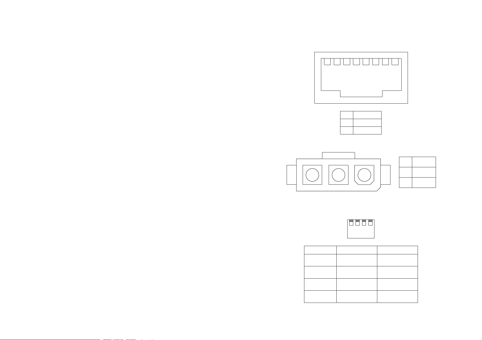
6.3.4 TRANSMISSION LINE PIN OUT
6.3.5 DC CONNECTOR PIN OUT
6.4 SWITCH SETTINGS
The switch is located under a removable panel on the rear of the unit.
6
ATL User Guide
AM100 MModem
3.2.2.3 SYNCHRONISATION 14
6. SPECIFICATION 15
6.2 AM100 DIMENSIONS 15
6.2 TRANSMISSION PERFORMANCE 15
6.3 CONNECTION PIN OUT 16
6.3.1 X21 USER INTERFACE PIN OUT 16
6.3.2 V35 USER INTERFACE PIN OUT 17
6.3.3 G703 USER INTERFACE PIN OUT 18
6.3.4 TRANSMISSION LINE PIN OUT 19
6.3.5 DC CONNECTOR PIN OUT 19
6.4 SWITCH SETTINGS 19
6.5 ENVIRONMENTAL 20
6.5.1 TRANSPORTATION 20
6.5.2 STORAGE 20
6.5.3 OPERATIONAL 20
7. COMPLIANCE NOTES 21
7.1 TELECOMMUNICATION STANDARDS 21
8. TROUBLE SHOOTING 22
8.1 QUICK GUIDE TO BASIC FAULT FINDING 22
8.2 LINK PERFORMANCE 22
8.2.1 LOCAL LOOP 22
8.2.2 REMOTE LOOP 23
8.2.3 FAR END LOCAL LOOP 23
8.2.4 LOOP BACK 23
9. ORDERING INFORMATION 24
9.1 AM100 DC POWERED 24
9.2 AM100 AC POWERED 24
9.3 MOUNTING BRACKET 24
9.3 ACCESSORIES 24
1 2 3 4 5 6 7 8
1
Line A
2
Line B
3-8
Unused
2 13
1234
Switch DownUp (default)
1
2
3
4
V54 loops
Enabled
RXD flashing
Enabled
Rate & Mode
buttons Enabled
Loop buttons
Enabled
V54 loops
Disabled
RXD flashing
Disabled
Rate & Mode
buttons Disabled
Loop buttons
Disabled
12-48V
0V
3 CGND
Page 7
7
ATL User Guide
AM100 MModem
1 SCOPE
This User Guide applies to the AM100 modem designed and manufactured by ATL Telecom Limited
in the U.K. It provides guidance for installation, commissioning and operation of the modem as well
as reference information covering maintenance, specification and compliance.
18
ATL User Guide
AM100 MModem
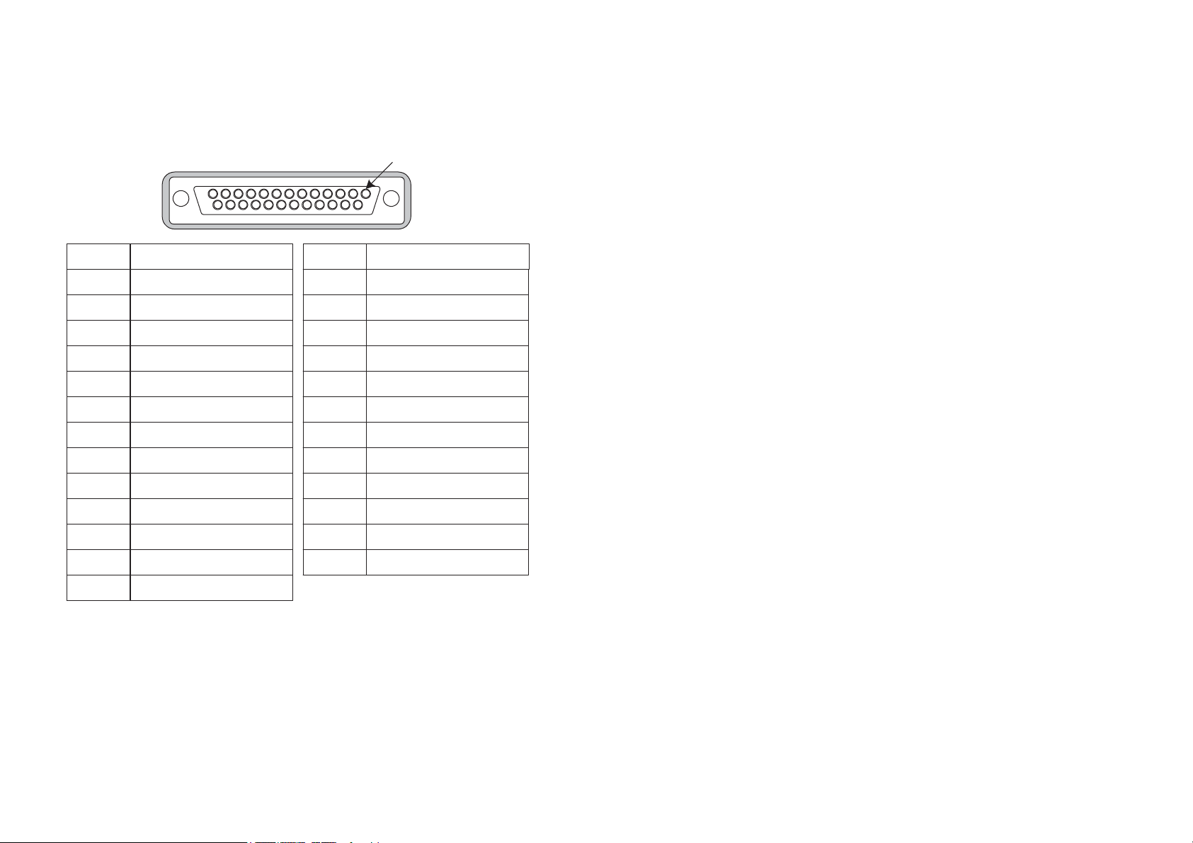
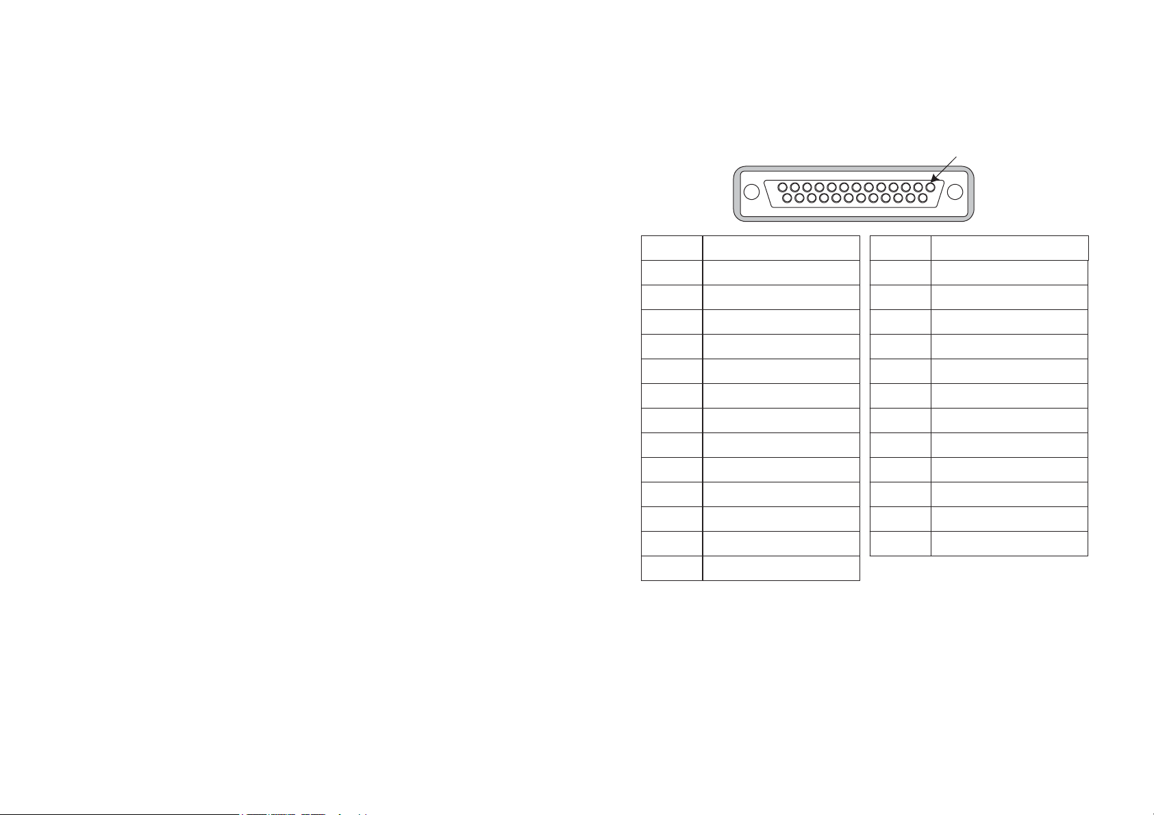
6.3.3 G703 USER INTERFACE PIN OUT
Pin Out
1
2
3
4
5
6
7
8
9
10
Name
TA-A
TX-B
Pin Out
14
15
16
17
18
19
20
21
22
23
Pin 1
Name
RX-A
RX-B
11
12
13
24
25
Page 8
17
ATL User Guide
AM100 MModem
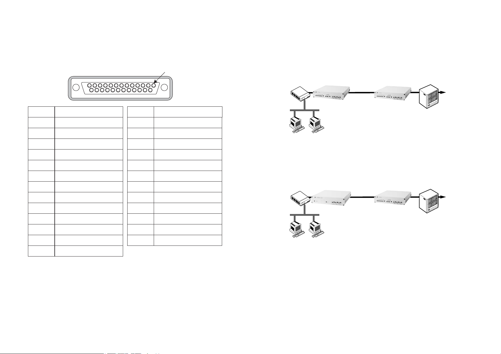
6.3.2 V35 USER INTERFACE PIN OUT
8
ATL User Guide
AM100 MModem
2 INTRODUCTION
The AM100 is a DSL modem that is capable of transmitting up to 4.9 Km at 640kbps over 0.5mm
2
cable (9.8Km at 64kbps).
The AM100 supports transmission rates from 64kbps to 640kbps over a single pair copper line.
The AM100 provides either X.21, V.35 or G.703 interface options. All of the interfaces require the
use of a special converter cable that attaches to the 25 way D-type connector on the back of the
AM100.
The X.21 & V.35 variants can be set to operate in either ‘master’ or ‘slave’ mode. The G.703 is only
available in ‘master’ mode.
Pin 1
Pin Out
1
2
3
4
5
6
7
8
9
10
Name
CGND
103_A
104_A
105_A
106_A
107_A
GND
109_A
115_B
Pin Out
14
15
16
17
18
19
20
21
22
23
Name
103_B
114_A
104_B
115_A
141_A
105_B
108_A
140_A
CGND
CGND
11
12
13
113_B
114_B
CGND
24
25
113_A
142_A
Page 9
ATL User Guide
AM100 MModem
3 EXAMPLE APPLICATIONS
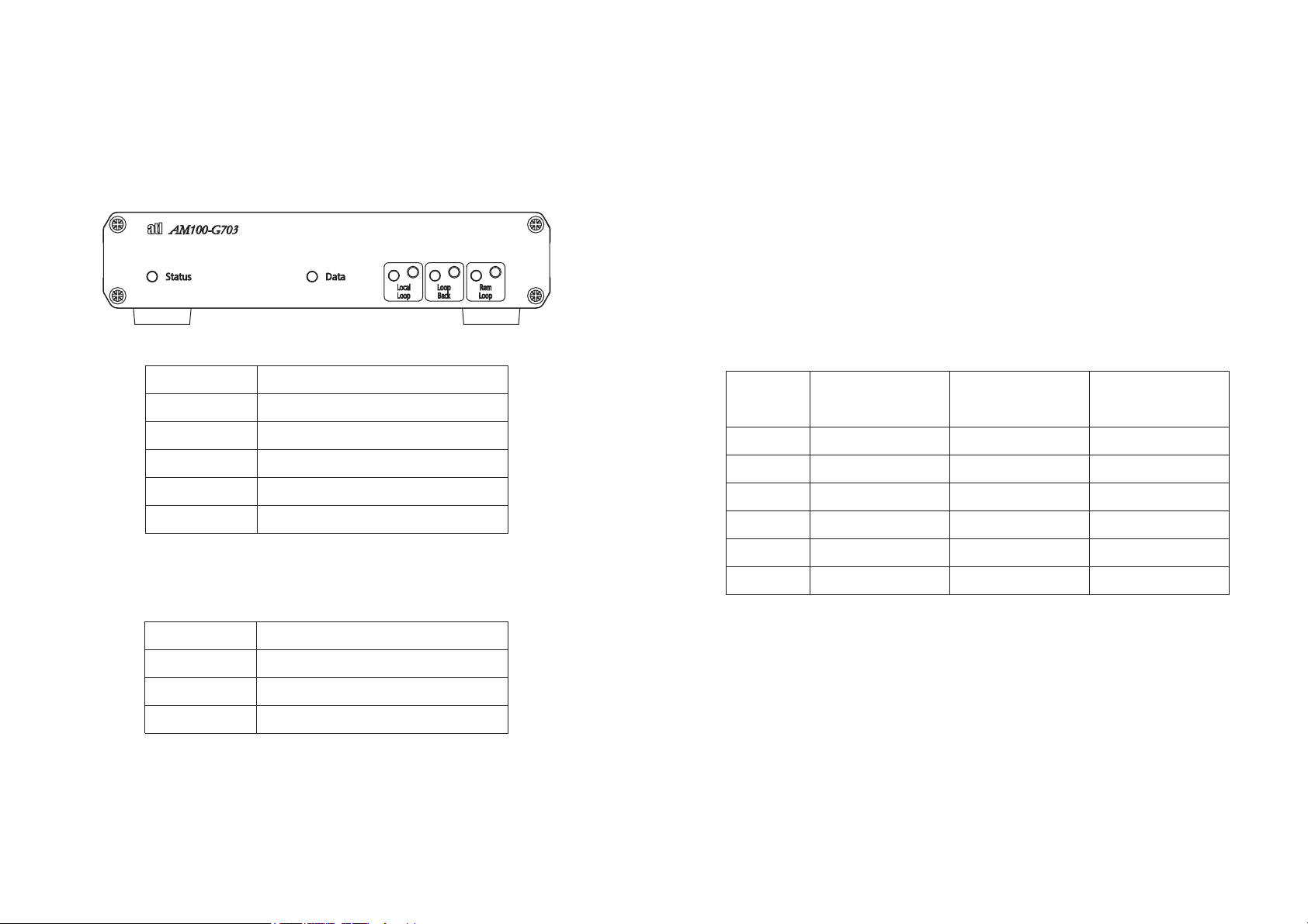
The diagrams below illustrate some basic applications.
3.1 DATA LINK WITH NO EXTERNAL TIMING
Figure 1
Either end of the link may be set to ‘master’, with the opposite end set to ‘slave’. The timing
originates from the internal clock of the master and is sent out to the customer’s unit.
3.2 DATA LINK WITH EXTERNAL TIMING
Fugure 2
In this example the master modem accepts timing from the G.703, X.21 or V.35 interface and uses
this to time the link.
16
ATL User Guide
AM100 MModem
6.3 CONNECTION PIN OUT
6.3.1 X21 USER INTERFACE PIN OUT
9
Pin Out
1
2
3
4
5
6
7
8
9
10
Name
T-A
R-A
C-A
GND
I-A
S-B
I-B
Pin Out
14
15
16
17
18
19
20
21
22
23
Pin 1
Name
T-B
R-B
S-A
C-B
Router Switch
LAN
AM100 V35 or X21
Master
Twisted Copper
pair
AM100 G703, X21 or V35
Router Switch
Twisted Copper
pair
LAN
Master
AM100 V35 or X21
Slave
AM100 V35 or X21
Slave
DATA
NETWORK
DATA
NETWORK
11
12
13
External Time-A
24
25
External Time-B
Page 10
15
ATL User Guide
AM100 MModem
6. SPECIFICATION
6.2 AM100 DIMENSIONS
The overall dimensions of the unit are:
Height = 170mm
Width = 220mm
Depth = 50mm
6.2 TRANSMISSION PERFORMANCE
The transmission performance figures for 0.4mm, 0.5mm & 0.6mm wire gauges are shown below.
The 0.4mm figures are actual typical values. The 0.5mm & 0.6mm are calculated values.
10
ATL User Guide
AM100 MModem
4. CONSTRUCTION
4.1 FRONT PANEL
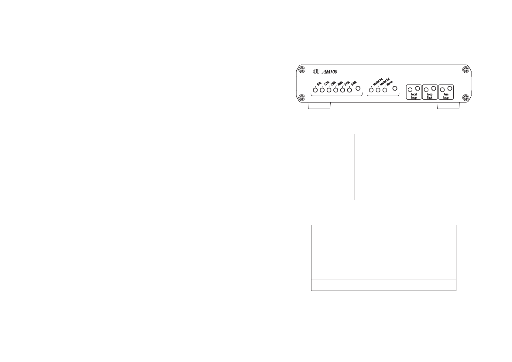
4.1.1 AM100 G.703 VARIANT
4.1.1.1 LEDS
4.1.1.2 BUTTONS
c
D
LED Function
Status Red when not in sync, green when in syn
Data
Local Loop Green when local loop is on
Loop Back Green when loop back is on
Rem Loop Green when remote loop is on
Red when RXD data is 1, green when RX
data is 0
LINE SPEED
64kbps
128kbps
256kbps
384kbps
512kbps
640kbps
0.4mm WIRE GAUGE
NOISE FREE RANGE
Km
7.4km
5.8km
4.6km 6.1km
0.5mm WIRE GAUGE
NOISE FREE RANGE
Km
9.8km
7.8km
7.6km5.6km
5.3km4.2km
4.9km3.7km
0.6mm WIRE GAUGE
NOISE FREE RANGE
Km
12.5km
9.9km
9.5km
7.8km
7.1km
6.2km
Button Function
Local Loop Turns Local Loop on and off
Loop Back Turns Loop Back on and off
Rem Loop Turns Remote Loop on and off
Page 11
11
ATL User Guide
AM100 MModem
4.1.2 AM100 V.35 & X.21 VARIANTS
4.1.2.1 LEDS
4.1.2.2 BUTTONS
in
D
14
ATL User Guide
AM100 MModem
3.2.2 DATA LINK WITH EXTERNAL TIMING (G.703, V.35 & X.21 VARIANTS)
This type of circuit is illustrated in Figure 2. This configuration is similar to the previous
configuration. The Master modem however can be set to receive an external timing source.
3.2.2.1 CONFIGURING THE SLAVE UNIT
Press the Mode button until the Slave LED is lit.
3.2.2.2 CONFIGURING THE MASTER UNIT (V.35 & X.21 VARIANTS)
Press the Mode button until the Master ext Led is lit.
Press the Rate Button until the desired rate is lit red.
3.2.2.2 CONFIGURING THE MASTER UNIT (G.703 VARIANT)
No configuration is required.
3.2.2.3 SYNCHRONISATION
If the units are correctly connected then, after a couple of minutes the Rate LED will turn Green.
The units are now synchronized and transmitting data to one another and timing is being
transferred from the customer equipment to the slave user interface.
LED Function
Rate Indication /
Status
Mode Indication/
Data
Local Loop Green when local loop is on
Loop Back Green when loop back is on
Rem Loop Green when remote loop is on
Shows the transmission rate. Red when not
Indicates the selected mode. Red when RX
sync, green when in sync
data is 1, green when RXD data is 0
Button Function
Rate Selection
Mode Selection Used to select the required mode
Local Loop Turns Local Loop on and off
Loop Back Turns Loop Back on and off
Rem Loop Turns Remote Loop on and off
Used to select the required rate (master
mode)
Page 12
13
ATL User Guide
AM100 MModem
5. CONFIGURATION
5.1 CONNECTING THE AM100
The AM100 comes packaged complete with a suitable power lead and an RJ45 to RJ11 line cord.
Connect the power lead to the rear of the unit.
Plug one end of the line cord into the RJ45 line connector on the rear of the unit. The other end
connects to your copper line pair.
A suitable Stub lead is required to connect the modem user interface on the rear of the unit to
your DTE equipment. Details of the interface pin out can be found in section 6.3.
5.1.1 LED POWER ON SEQUENCE - V.35 & X.21 VARIANTS
During the power on sequence the LED's will flash back and forth and when finished one Rate and
one Mode LED will be lit.
5.1.2 LED POWER ON SEQUENCE - G703 VARIANT
During the power on sequence the LED's will flash and when finished the status and data LED’s
will be lit.
3.2 CONFIGURING THE AM100
3.2.1 DATA LINK WITH NO EXTERNAL TIMING (V.35 & X.21 VARIANTS)
This type of circuit is illustrated in Figure 1. One end of the link is configured as a MASTER and the
other end is configured as a SLAVE. The rate setting set at the MASTER unit will be downloaded
to the SLAVE automatically.
3.2.1.1 CONFIGURING THE SLAVE UNIT
Press the Mode button until the Slave LED is lit.
3.2.1.2 CONFIGURING THE MASTER UNIT
Press the Mode button until the Master Int Led is lit.
Press the Rate Button until the desired rate is lit red.
3.2.1.3 SYNCHRONISATION
If the units are correctly connected then, after a couple of minutes the Rate LED will turn Green.
The units are now synchronized and transmitting data to one another
12
ATL User Guide
AM100 MModem
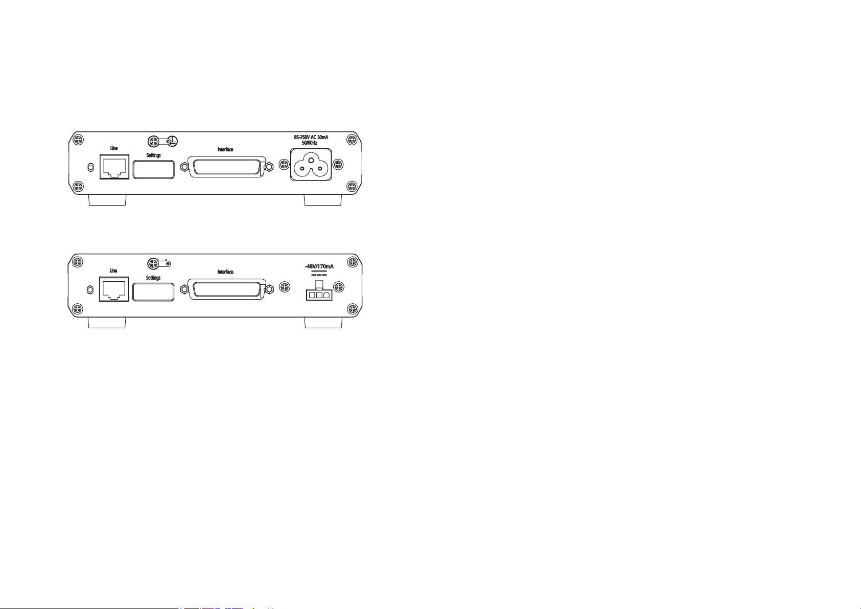
4.2 REAR PANEL
4.2.1 AC VARIANTS
4.2.2 DC VARIANTS
4.2,3 CONNECTORS
RJ45 Line connector
25 way D-type Interface connector
3 pin Mini Molex connector (DC variant)
3 pin IEC mains connector (AC variant)
4.2.4 CABLES
The AM100 is supplied with either an AC mains or DC cable ( ref Ordering Information). Plus a
Category 5 RJ45 to RJ11 line cord.
 Loading...