

Page 1

AM2 USER GUIDE
Page 2

ATL User Guide
AM2 G.SHDSL Modem
2
ATL Part No 1/359/001/610
Issue 02 June 2005
Disclaimer
The information contained in this document is confidential to ATL Telecom Ltd. and may not be disclosed or
reproduced in whole or in part without their written consent.
© ATL Telecom Ltd 2005.
Note: The information contained in this document is supplied without liability for errors or omissions.
ATL Telecom Limited reserves the right to make changes to this document at any time without notice.
Page 3

ATL User Guide
AM2 G.SHDSL Modem
3
COMPLIANCE NOTES & SAFETY INSTRUCTIONS
Caution: - Hazardous voltages inside the equipment
Safety Instructions:
This apparatus must be installed and maintained by SERVICE PERSONNEL only
There are NO user serviceable parts inside the modem.
Caution: - Electrostatic sensitive devices inside the equipment
Electrostatic discharge (ESD) Warning:
Antistatic precautions should be observed at all times.
Power Rating Information - DC Version:
Voltage Rating 9V
Maximum Current 1000mA
Disconnect Device Statement:
For the AM2 the DC input socket serves as the disconnect device.
Safety Classification of traffic Ports
The DSL line connection has a safety status of TNV-3
10/100BaseT - 8 WAY RJ45 connections have a safety status of UNEARTHED SELV.
Safety Status Classification of non-traffic PORTS
DC Input - TNV-2
Management Port Interface - 9 WAY FEMALE D-Type connection has a safety status of EARTHED SELV.
Definitions
Exposed Environment
A TELECOMMUNICATIONS NETWORK is considered to be an exposed environment if one or more conditions
for an unexposed environment are not fulfilled.
Page 4

ATL User Guide
AM2 G.SHDSL Modem
4
Unexposed Environment
A TELECOMMUNICATIONS NETWORK is considered to be an unexposed environment if the following
conditions apply to all parts of the network
a) The possible effect of indirect lightening has been reduced by measures described in IEC 61312-1.
b) The possibility of having different earth potentials has been reduced by connecting all equipment
within the network to the same equipotential bonding system.
c) The possibility of power cross/contact has been reduced.
d) The possibility of induced transients and voltages has been reduced.
Manufactur
ers Declaration*
ATL Telecom Limited declares that this product is in conformity
with the essential requirements of the 'R&TTE directive 1999/5/EC'.
*A copy of the Declaration of Conformity is available upon request from ATL Telecom Ltd.
Page 5

ATL User Guide
AM2 G.SHDSL Modem
5
1 SCOPE 9
2 INTRODUCTION 10
3 EXAMPLE APPLICATIONS 11
3.1 AM2 BACK TO BACK SET-UP 11
3.2 AM2 TO INTERNET VIA A DSLAM 11
E 4 CONSTRUCTION 12
4.1 AM2 FRONT PANEL 12
4.3 AM2 REAR PANEL 13
4.3.1 REAR CONNECTIONS 13
4.3.2 CABLES 13
4.3.3 POWER SUPPLY 13
5 INSTALLATION 14
5.1 LED POWER ON SEQUENCE 14
5.2 DEFAULT SETTINGS 14
6 SETTING UP USING THE WEB BROWSER 15
6.1 INTERNET/EXPLORER SET-UP 15
6.2 BASIC SETUP 18
6.3 BRIDGE 18
6.3.1 BRIDGE EXAMPLE - LAN TO LAN CONNECTION 18
6.3.1.1 AT THE CO UNIT 19
6.3.1.1.1 STEP 1 19
6.3.1.1.2 STEP 2 19
6.3.1.1.3 STEP 3 20
6.3.1.2 AT THE CPE UNIT 20
6.3.1.2.1 STEP 1 20
6.3.1.2.2 STEP 2 21
6.3.1.2.3 STEP 3 21
6.3.2 BRIDGE EXAMPLE - LAN TO DSLAM CONNECTION 22
6.4 ROUTING 24
6.4.1 DHCP SERVER 24
6.4.2 DHCP CLIENT 24
6.4.3 DCHCP RELAY 24
6.4.4 PPPOA & PPPOE 24
6.4.5 ROUTER EXAMPLE - LAN TO LAN CONNECTION 25
6.4.5.1 AT THE CO UNIT 25
6.4.5.1.1 STEP 1 25
6.4.5.1.2 STEP 2 26
6.4.5.1.3 STEP 3 26
6.4.5.1.4 STEP 4 27
Page 6

ATL User Guide
AM2 G.SHDSL Modem
6
6.4.5.1.5 STEP 5 27
6.4.5.2 AT THE CPE UNIT 28
6.4.5.2.1 STEP 1 28
6.4.5.2.2 STEP 2 28
6.4.5.2.3 STEP 3 29
6.4.5.2.4 STEP 4 29
6.4.5.2.5 STEP 5 30
6.5 ADVANCED SETUP 31
6.5.1 SHDSL 31
6.52 WAN 33
6.5.3 BRIDGE 35
6.5.4 VLAN 36
6.5.4.1 802.1Q VLAN 37
6.5.4.1 PORT-BASED VLAN 38
6.5.5 ROUTE 39
6.5.6 NAT/DMZ 42
6.5.6 VIRTUAL SERVER 44
6.5.7 FIREWALL 46
6.5.7.1 BASIC FIREWALL SECURITY 47
6.5.7.2 AUTOMATIC FIREWALL SECURITY 48
6.5.7.3 ADVANCED FIREWALL SECURITY 49
6.5.7.4FILTERING RULE FOR SMTP CONNECTION 52
6.6 STATUS 55
6.6.1 SHDSL 55
6.6.2 LAN 56
6.6.3 WAN 56
6.6.4 ROUTE 57
6.6.5 INTERFACE 57
6.7 ADMINISTRATION 58
6.7.1 SECURITY 58
6.7.2 SNMP 60
6.7.3 TIME SYNC 62
6.8 UTILITY 63
6.8.1 SYSTEM INFO 63
6.8.2 CONFIG TOOL 64
6.8.3 UPGRADE 65
6.7.4 LOGOUT 65
6.7.5 RESTART 65
7 CONFIGURATION VIA THE CONSOLE PORT 66
7.1 CONNECTION VIA THE CONSOLE PORT 66
Page 7

ATL User Guide
AM2 G.SHDSL Modem
7
7.2 CONNECTION VIA TELNET 66
7.3 MENU DRIVEN INTERFACE 67
7.3.1 MENU STRUCTURE 68
7.3.2 ENABLE 69
7.3.2.1 SETUP 70
7.3.2.1.1 MODE 71
7.3.2.1.2 SHDSL 71
7.3.2.1.3 WAN 72
7.3.2.1.4 BRIDGE 74
7.3.2.1.5 VLAN 75
7.3.2.1.6 ROUTE 77
7.3.2.1.7 LAN 78
7.3.2.1.8 IP SHARE 78
7.3.2.1.9 FIREWALL 83
7.3.2.110 DHCP 85
7.3.2.1.11 DNS PROXY 86
7.3.2.1.12 HOSTNAME 86
7.3.2.1.13 DEFAULT 86
7.3.2.2 STATUS 86
7.3.2.3 SHOW 87
7.3.2.4 WRITE 88
7.3.2.5 REBOOT 88
7.3.2.6 PING 88
7.3.2.7 ADMIN 89
7.3.2.8 UTILITY 93
7.4 COMMAND LINE INTERFACE 93
7.4.1 SETTING UP THE CLI INTERFACE 94
7.4.2 SETTING UP THE MENU DRIVEN INTERFACE 94
8 COMMISSIONING 95
9 SPECIFICATION 96
9.1 AM2 DIMENSIONS 96
9.2 TRANSMISSION PERFORMANCE 97
9.2.1 2-WIRE NOISE FREE RANGE 97
9.2.2 4-WIRE NOISE FREE RANGE 98
9.3 ENVIRONMENTAL 99
9.3.1 TRANSPORTATION 99
9.3.2 STORAGE 99
9.3.3 OPERATIONAL 99
9.4 LAN CONNECTION CABLE 100
9.5 CONSOLE CONNECTION CABLE 100
Page 8

ATL User Guide
AM2 G.SHDSL Modem
8
10 COMPLIANCE NOTES 101
10.1 TELECOMMUNICATION STANDARDS 101
11 ORDERING INFORMATION 102
12 APPENDIX 1 GLOSSARY 103
Page 9

ATL User Guide
AM2 G.SHDSL Modem
9
1
1 SCOPE
This User Guide applies to the AM2 G.SHDSL Modem supplied by ATL Telecom Limited in the U.K. It provides
guidance for installation, commissioning and operation of the AM2 as well as reference information covering
maintenance, specification and compliance.
Page 10
ATL User Guide
AM2 G.SHDSL Modem
10
2 INTRODUCTION
The AM2 SHDSL (Single-Paired High Speed Digital Subscriber Loop) modem complies with the G.991.2
standard with 10/100 Base-T auto-negotiation. It provides business-class, multi-range from 64kbps to
2.304Mbps. The AM2 is designed not only to optimize the service bit rate from central office to customer
premises, it also integrates high-end Bridging/Routing capabilities with advanced Multi-DMZ, virtual server
mapping and VPN pass-through functions.
Because of the rapid growth of networks, virtual LAN has become one of the major new areas in the
internetworking industry. The AM2 supports port-based and IEEE 802.1q VLAN over ATM network.
The AM2 provides not only advanced functions, Multi-DMZ, virtual server mapping and VPN pass-through but
advanced firewall, SPI, NAT, DoS protection serving as a powerful firewall to protect the secure connection
from outside intruders. (Note: Firewall available only on AM2F variant - see Ordering Information for details.)
The AM2 supports 10Base-T /100Base-T auto-negotiation on the LAN port to meet the enterprise needs of
modern networks.
The AM2 allows customers to leverage the latest in broadband technologies to meet their growing data
communication needs. Through the power of SHDSL products, you can access superior manageability and
reliability.
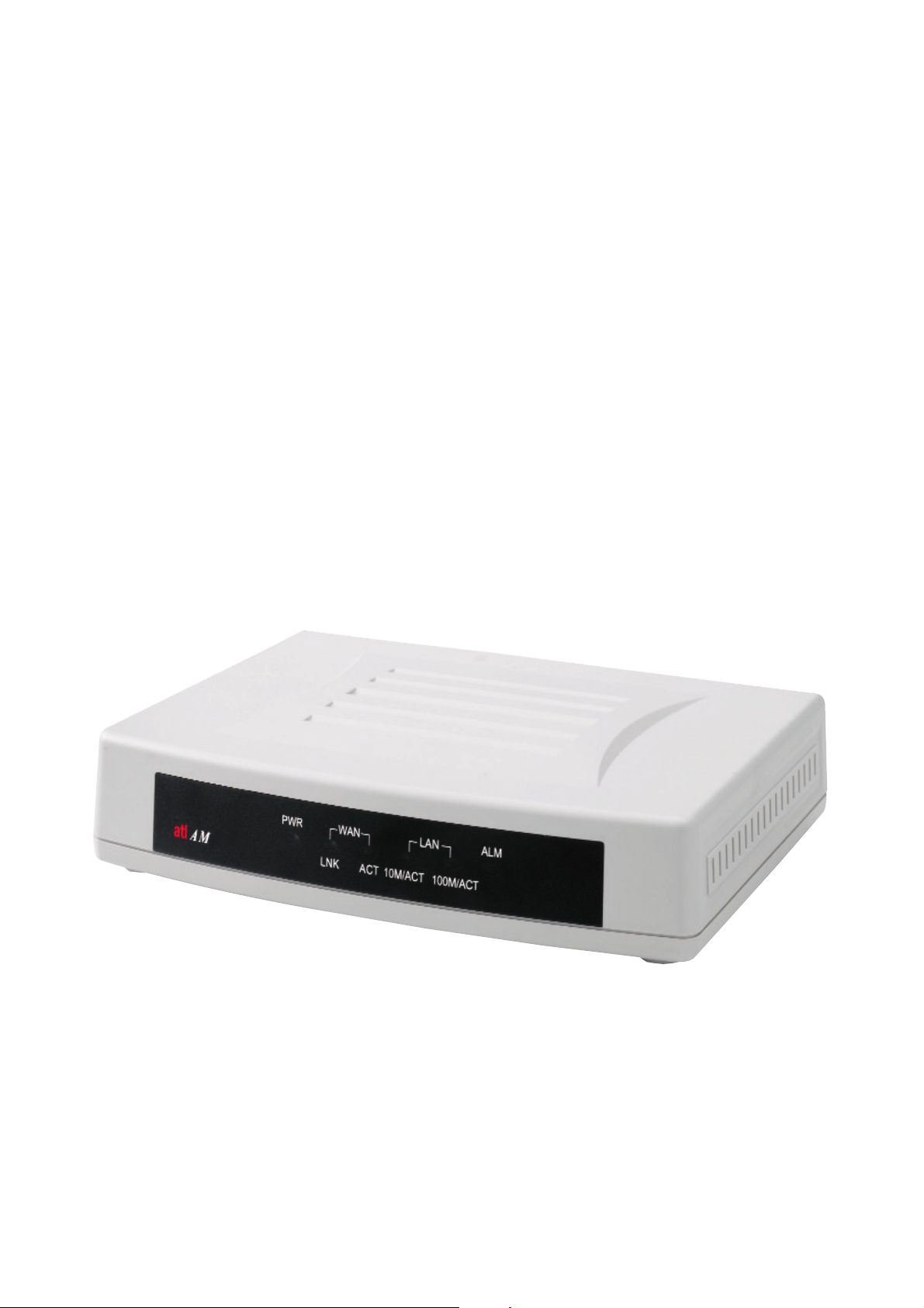
Figure 1 : AM2
Page 11
ATL User Guide
AM2 G.SHDSL Modem
11
3
3 EXAMPLE APPLICATIONS
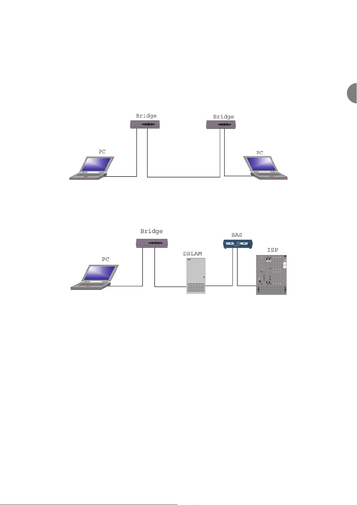
The following examples illustrate some of the applications.
3.1 AM2 BACK TO BACK SET-UP
Due to the flexibility of the AM2 unit, it can be connected back-to-back to give high-speed data transmission
between two sites.
Figure 2 Example showing connection between two sites
3.2 AM2 TO INTERNET VIA A DSLAM
Figure 3 AM2 Connected to a DSLAM
Page 12

ATL User Guide
AM2 G.SHDSL Modem
12
e 4 CONSTRUCTION
The AM2 is a desktop unit housed in a non-flammable plastic case (UL94 rating V0).
4.1 AM2 FRONT PANEL
The front panel of the AM2 is shown below. The LEDs show the current state of the AM2
LEDS
LEDs Active Description
WAN
LNK
PWR
On
Flashing
On
On
ACT
Power On
LAN
1
Flashing
On
2
Flashing
On
3
Flashing
On
4
Flashing
On
ALM
Flashing
On
SHDSL Line connection is established
SHDSL handshake
Transmit or received data over SHDLS link
Ethernet cable is connected to LAN 1
Transmit or received data over LAN 1
Ethernet cable is connected to LAN 2
Transmit or received data over LAN 2
Ethernet cable is connected to LAN 3
Transmit or received data over LAN 3
Self Test
SHDSL line connection is dropped
Transmit or received data over LAN 4
Ethernet cable is connected to LAN 4
PWR LNK ACT
1 2 3 4
ALM
WAN
LAN
Front Panel of AM2 Modem
atl
AM2
Page 13
ATL User Guide
AM2 G.SHDSL Modem
13
4
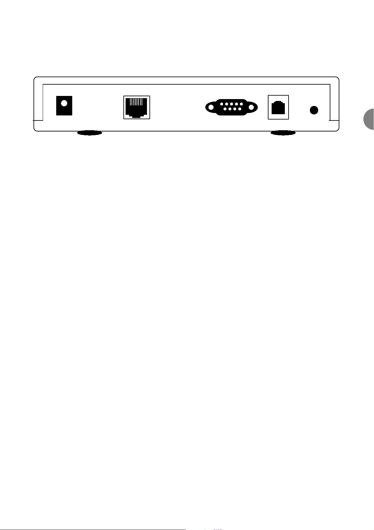
4.3 AM2 REAR PANEL
4.3.1 REAR CONNECTIONS
DC-IN 9V DC Power Inlet
LAN 10/100 BaseT RJ45 LAN Port
CONSOLE RS-232C 9-way D type System Configuration Port
LINE Line Connection RJ11 Port
RST Reset/Reboot Button
Warning - Pressing the RST button for one second will result in a system reboot.
Pressing the RST button for four sends will result in the unit reloading the factory default
settings. All of the configurations you have carried out will be lost.
4.3.2 CABLES
The AM2 is supplied with a 2 metre line cord terminated with RJ11 plugs at both ends. Plus a RS232 cable
for connection to the console port.
4.3.3 POWER SUPPLY
The AM2 is supplied either with an UK PSU (1/359/001,1/359/011) or an EU PSU (1/359/002,1/359/012)
Rear Panel of AM2 Modem
DC-IN
LAN
CONSOLE
LINE
RST
Page 14

ATL User Guide
AM2 G.SHDSL Modem
14
5 INSTALLATION
This chapter describes the basic steps that are required to set up a system using the AM2. It is recommended
that if two desktop units are to be connected they should be tested back to back to check for correct
operation before deployment.
5.1 LED POWER ON SEQUENCE
During the power up/self test sequence the WAN LNK and ACT LEDs are both on continuously and the ALM
led flashes for around 14 seconds. The WAN LNK and ACT LEDs will then go out and the four LAN LEDs will
flash once.
5.2 DEFAULT SETTINGS
IP Address 10.254.254.253
Mask 255.255.0.0
Interface Link IPoA
Data Rate 0 (rate adaptive)
Annex Type Annex_B
Host Name SOHO
Network Type Global
VPI 0
VCI 32
ENCAP LLC
QoS UBR
PCR 4800
Rip Mode Disabled
VLAN Disabled
Gateway IP Address 192.168.0.254
Page 15
ATL User Guide
AM2 G.SHDSL Modem
15
6
6 SETTING UP USING THE WEB BROWSER
The easiest way to configure the AM2 is via the web browser.
The default IP address for the AM2 unit is 192.168.0.1.
The default configuration user name and password is root.
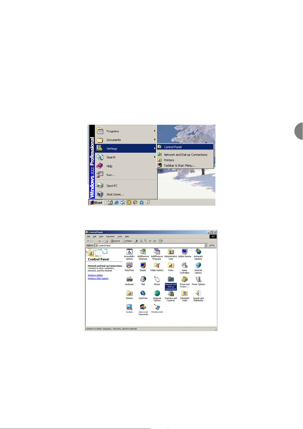
6.1 INTERNET/EXPLORER SET-UP
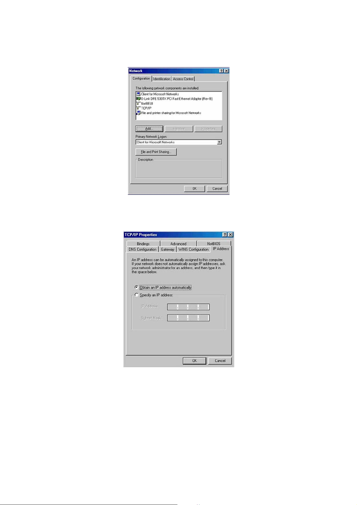
For Win85, 98 and Me, click on the Start button. Select the Setting option and then the Control Panel
option.
The Control Panel screen is then displayed. Double click on the Network icon
I
Page 16
ATL User Guide
AM2 G.SHDSL Modem
16
Select the Configuration tab. In the Configuration window, select the TCP/IP protocol line that has been
associated with your network card and then click on the Property icon
Select the IP Address tab. Select the Obtain IP address automatically option and then click on the OK
button.
Windows will now ask you to restart the PC. Click on the Yes button.
Page 17
ATL User Guide
AM2 G.SHDSL Modem
17
6
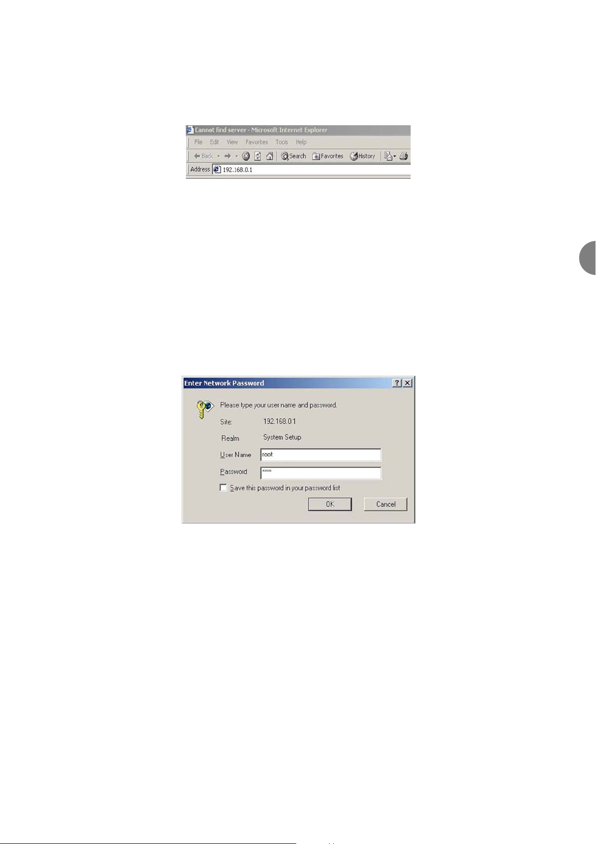
After restarting your PC, open the Inernet Explorer or Netscape Browser to connect to the AM2. Type in the
default IP address for the AM2 into the Address/URL Line of the browser and press the Return key., e.g.
http://192.168.0.1
The default IP address and sub net-mask of the AM2 is 192.168.0.1 and 255.255.255.0. Because the AM2
acts as a DHCP server in your network, the AM2 will automatically assign an IP address for your PC in the
network.
Note:- If you have two or more AM2 units connected to the same network then you must change the IP
address of the AM2.
You will now be prompted to type in the default User Name and Password and click on the OK button.
The default User Name is root.
The default password is root.
For security reasons we suggest you change both the user name and password. Ref to section 6.7
Page 18
ATL User Guide
AM2 G.SHDSL Modem
18
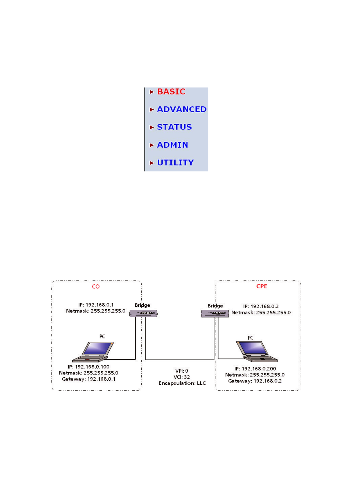
6.2 BASIC SETUP
The Basic Setup contains LAN, WAN, Bridge and Route operation modes. Thus offering all of the features
required to setup the AM2. This is the easiest way to setup the AM2. From the main menu select the Basic
option.
Note: The advanced functions are only for advanced users with experience of setting up modems and routers.
Incorrect setting of any of the advanced functions will affect the performance of the AM2 or will result in
system errors.
6.3 BRIDGE
6.3.1 BRIDGE EXAMPLE - LAN TO LAN CONNECTION
In the following example two AM2 units will be configured to connect two LANs.The section will cover the
configuration of both the CO (Central Office) unit and the CPE (Customers Premises Equipment) unit .Before
you configure the AM2 it is advisable to check with your ISP that the gateway, and WAN details you are going
to use are correct.
Page 19
ATL User Guide
AM2 G.SHDSL Modem
19
6
6.3.1.1 AT THE CO UNIT
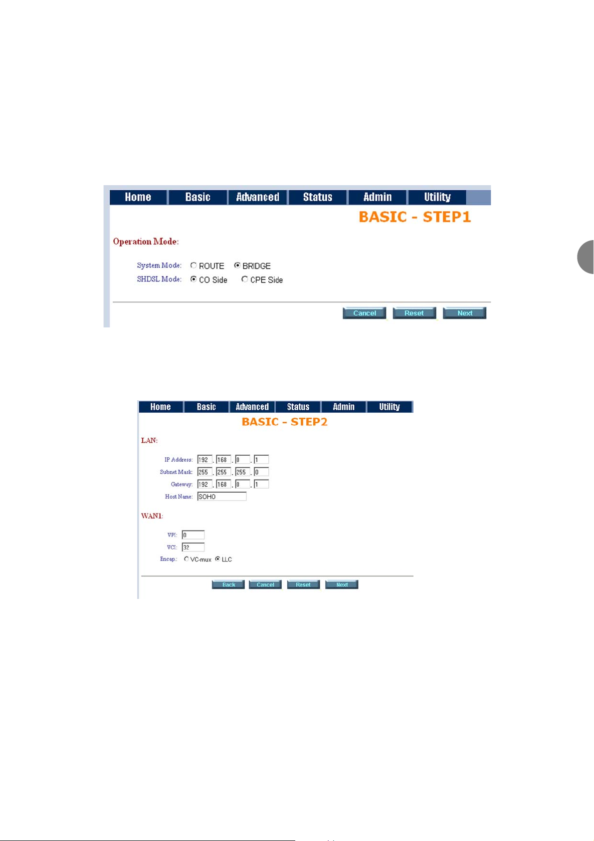
The following outlines the steps that need to be followed to setup the unit as a CO Bridge unit.
6.3.1.1.1 STEP 1
From the options displayed, select the Bridge and CO Side options. Then click on the Next button
6.3.1.1.2 STEP 2
On the next screen, type in the IP Address, Subnet Mask, Gateway Address Host Name and WAN details. For
the example shown the following details would be entered.
Note:- Some ISP require the host name to be entered, although in most cases this field can be left blank.
Once you have entered the required details, click on the Next button.
Note at any point during the configuration section you can either, cancel the configuration, reset the
configuration or return to the previous screen by using the appropriate button located at the bottom of the
screen.
Page 20
ATL User Guide
AM2 G.SHDSL Modem
20
6.3.1.1.3 STEP 3
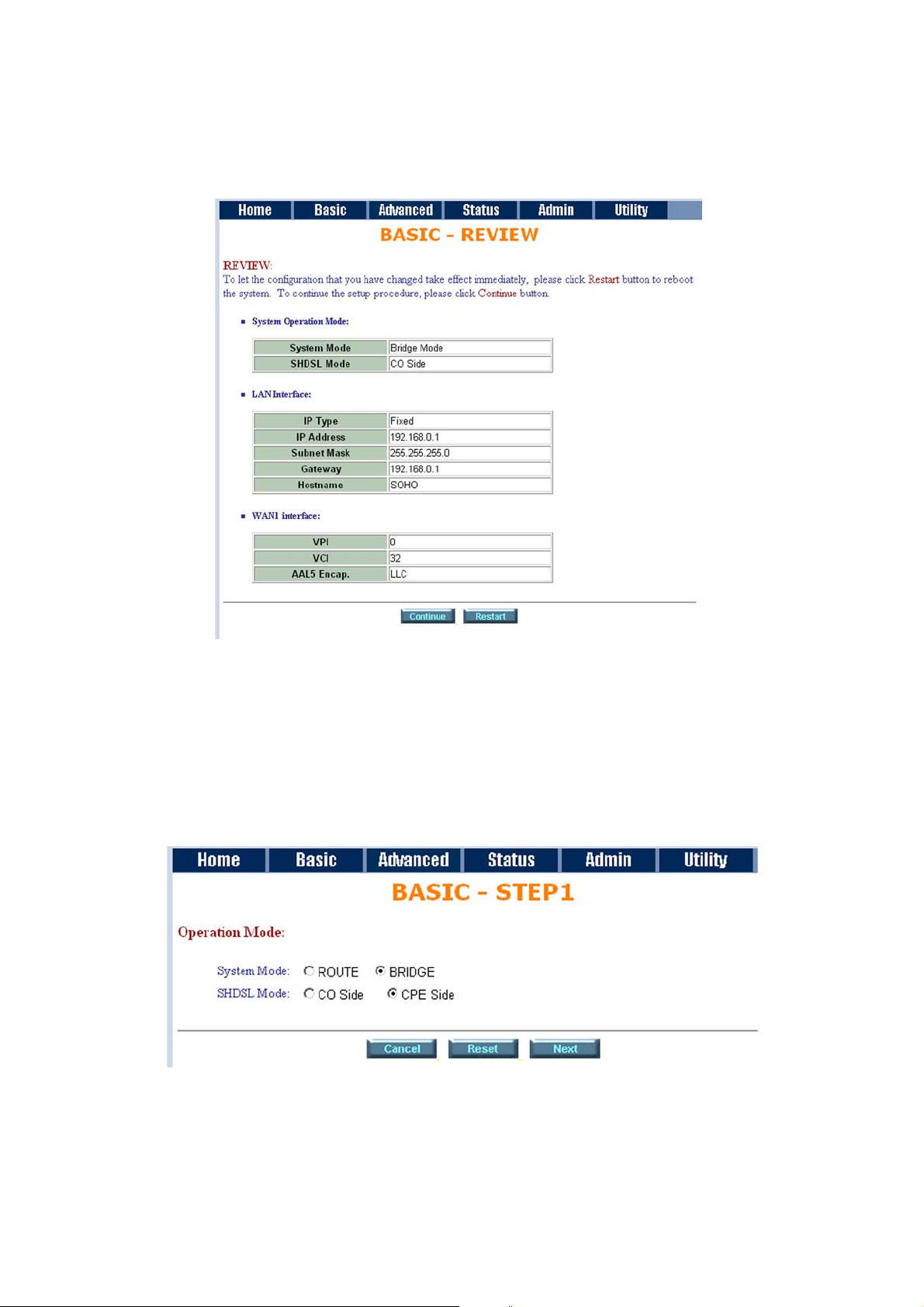
The next screen will now prompt you to verify that the details you have entered are correct. If everything is
correct, click on the Restart button. The unit will now be rebooted with the new settings.
6.3.1.2 AT THE CPE UNIT
The following outlines the steps that need to be followed to setup the unit as a CPE and Bridge.
6.3.1.2.1 STEP 1
From the options displayed, select the Bridge and CPE Side options. Then click on the Next button
Page 21

ATL User Guide
AM2 G.SHDSL Modem
21
6
6.3.1.2.2 STEP 2
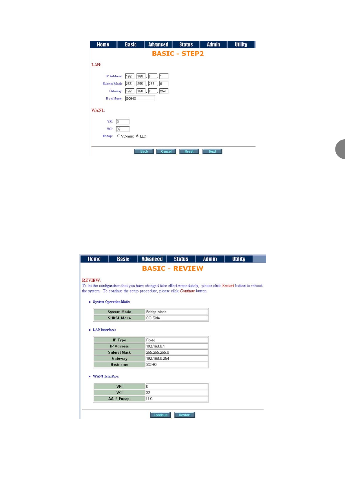
On the next screen, type in the IP Address, Subnet Mask, Gateway Address Host Name and WAN details. For
the example shown the following details would be entered.
Once you have entered the required details, click on the Next button.
6.3.1.2.3 STEP 3
The next screen will now prompt you to verify the details that you have entered are correct. If everything is
correct, click on the Restart button. The unit will now be rebooted with the new settings.
Page 22
ATL User Guide
AM2 G.SHDSL Modem
22
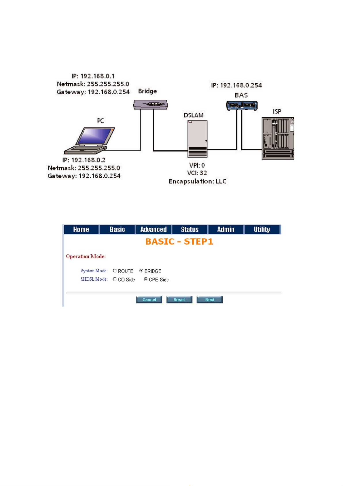
6.3.2 BRIDGE EXAMPLE - LAN TO DSLAM CONNECTION
The following outlines the steps that need to be followed to setup the unit as a CPE and Bridge.
From the main menu select the Basic option. From the options displayed, select the Bridge and CPE Side
options. Then click on the Next button
On the next screen, type in the IP Address, Subnet Mask, Gateway Address Host Name and WAN details. For
the example shown the following details would be entered.
Page 23
ATL User Guide
AM2 G.SHDSL Modem
23
6
Note:- Some ISP require the host name to be entered, although in most cases this field can be left blank.
Once you have entered the required details, click on the Next button.
Note at any point during the configuration section you can either, cancel the configuration, reset the
configuration or return to the previous screen by using the apropriate button located at the bottom of the
screen.
The next screen will now prompt you to verify the details that you have entered are correct. If everything is
correct, click on the Restart button. The unit will now be rebooted with the new settings.
Page 24

ATL User Guide
AM2 G.SHDSL Modem
24
6.4 ROUTING
Various Internet protocols are available i.e. DHCP server, DHCP client, DHCP relay, point-to-point over ATM,
Ethernet and IP over ATM and Ethernet over ATM. Prior to setting up the AM2 as a router you must ensure
which protocol is provided by the ISP.
6.4.1 DHCP SERVER
Dynamic Host Configuration Protocol (DHCP) is a communication protocol that lets network administrators to
manage centrally and automate the assignment of Internet Protocol (IP) addresses in an organization's
network. Using the Internet Protocol, each machine that can connect to the Internet needs a unique IP
address. When an organization sets up its computer users with a connection to the Internet, an IP address
must be assigned to each machine.
Without DHCP, the IP address must be entered manually at each computer. If computers move to another
location in another part of the network, a new IP address must be entered. DHCP lets a network administrator
supervise and distribute IP addresses from a central point and automatically sends a new IP address when a
computer is plugged into a different place in the network. If the DHCP server is Enabled, you have to setup
the following parameters for processing it as DHCP server.
The embedded DHCP server assigns network configuration information to most of the 253 users accessing
the Internet in the same time.
6.4.2 DHCP CLIENT
Some ISPs provide a DHCP server service by which the LAN can access IP information automatically. To setup
the DHCP client mode, follow the procedure.
6.4.3 DCHCP RELAY
If you have a DHCP server in your LAN and you want to use it for DHCP services, the product provides DHCP
relay function to meet your needs.
6.4.4 PPPoA & PPPoE
PPPoA (point-to-point protocol over ATM) and PPPoE (point-to-point protocol over Ethernet) are
authentication and connection protocols used by many service providers for broadband Internet access. These
are specifications for connecting multiple computer users on an Ethernet local area network to a remote site
through common customer premises equipment, which is the telephone company's term for a modem and
similar devices. PPPoE and PPPoA can be used to office or building. Users share a common Digital Subscriber
Line (DSL), cable modem, or wireless connection to the Internet. PPPoE and PPPoA combine the Point-to-Point
Protocol (PPP), commonly used in dialup connections, with the Ethernet protocol or ATM protocol, which
supports multiple users in a local area network. The PPP protocol information is encapsulated within an
Ethernet frame or ATM frame.
Page 25
ATL User Guide
AM2 G.SHDSL Modem
25
6
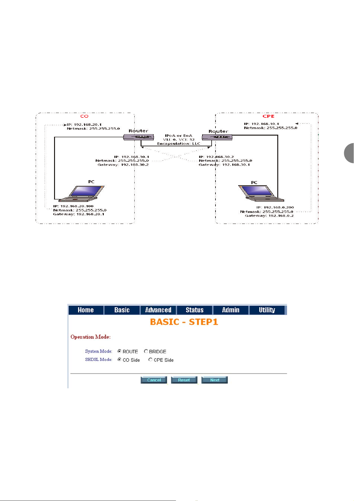
6.4.5 ROUTER EXAMPLE - LAN TO LAN CONNECTION
In the following example two AM2 units will be configured to connect two LANs.The section will cover the
configuration of both the CO (Central Office) unit and the CPE (Customers Premises Equipment) unit .Before
you configure the AM2 it is advisable to check with your ISP that the gateway, and WAN details you are going
to use are correct.
6.4.5.1 AT THE CO UNIT
The following outlines the steps that need to be followed to setup the unit as a CO Route unit.
6.4.5.1.1 STEP 1
From the options displayed, select the Route and CO Side options. Then click on the Next button
Page 26
ATL User Guide
AM2 G.SHDSL Modem
26
6.4.5.1.2 STEP 2
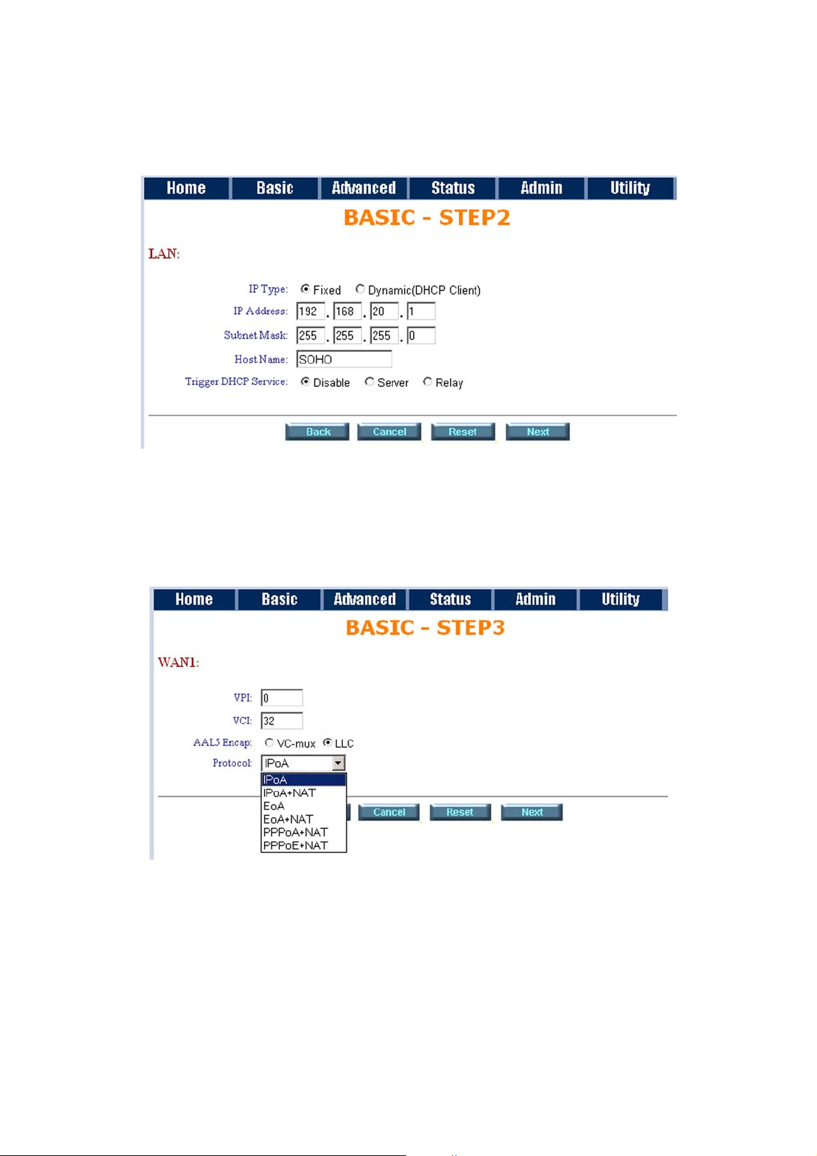
On the next screen, type in the IP Address, Subnet Mask and Host Name. You also need to decide if the DHCP
Service needs to be set to enable or disable. For the example shown the following details should be entered.
6.4.5.1.3 STEP 3
Enter the WAN Parameters and choose the required Protocol from the drop-down menu. Note, the protocol
used in the CO and the CPE must be the same.
Page 27
ATL User Guide
AM2 G.SHDSL Modem
27
6
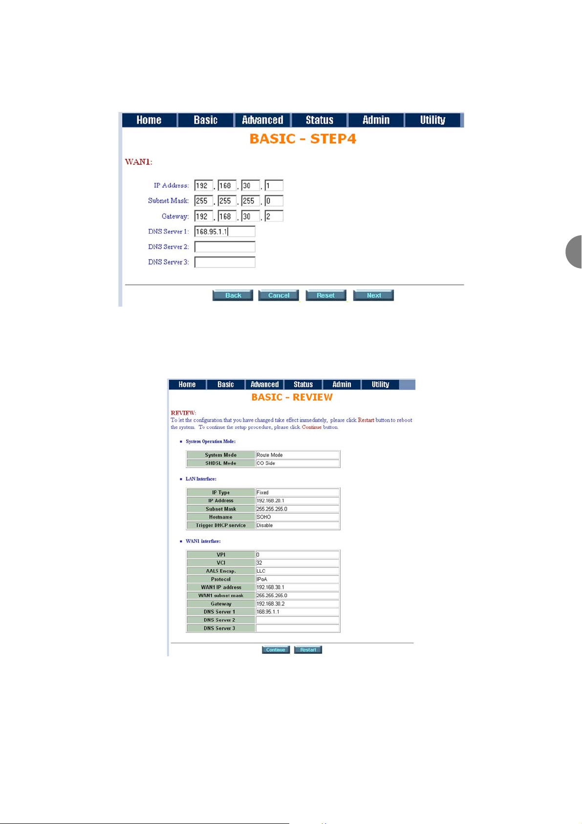
6.4.5.1.4 STEP 4
Enter the WAN IP Address, subnet mask and the gateway address
6.4.5.1.5 STEP 5
The next screen will now prompt you to verify the details that you have entered are correct. If everything is
correct, click on the Restart button. The unit will now be rebooted with the new settings.
Page 28
ATL User Guide
AM2 G.SHDSL Modem
28
6.4.5.2 AT THE CPE UNIT
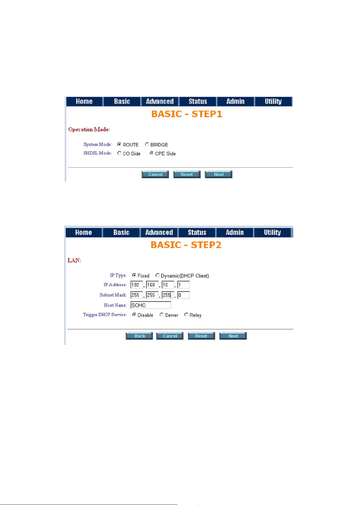
The following outlines the steps that need to be followed to setup the unit as a CPE Route unit.
6.4.5.2.1 STEP 1
From the options displayed, select the Route and CPE Side options. Then click on the Next button
6.4.5.2.2 STEP 2
On the next screen, type in the IP Address, Subnet Mask and Host Name. You also need to decide if the DHCP
Service needs to be set to enable or disable. For the example shown the following details should be entered.
Page 29
ATL User Guide
AM2 G.SHDSL Modem
29
6
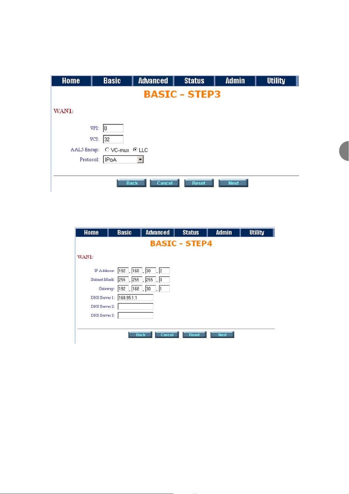
6.4.5.2.3 STEP 3
Enter the WAN Parameters and choose the required Protocol from the drop-down menu. Note, the protocol
used in the CO and the CPE must be the same.
6.4.5.2.4 STEP 4
Enter the WAN IP Address, subnet mask and the gateway address
Page 30
ATL User Guide
AM2 G.SHDSL Modem
30
6.4.5.2.5 STEP 5
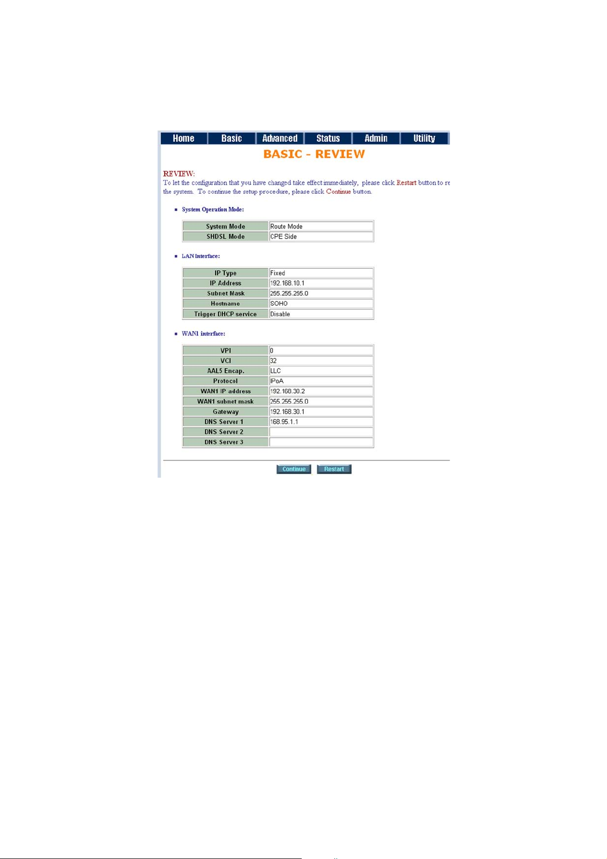
The next screen will now prompt you to verify the details that you have entered are correct. If everything is
correct, click on the Restart button. The unit will now be rebooted with the new settings.
Page 31
ATL User Guide
AM2 G.SHDSL Modem
31
6
6.5 ADVANCED SETUP
The following section covers the configuration of the AM2 using the Advanced menu.
6.5.1 SHDSL
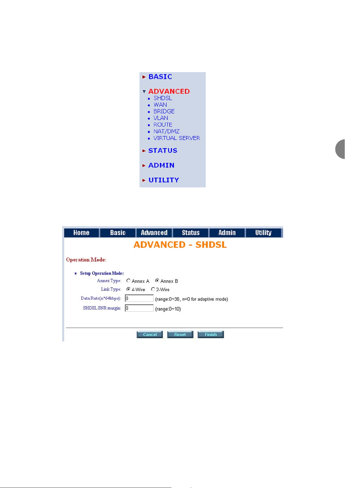
Using the SHDSL option,you can setup the Annex type, link type, data rate and SNR margin for the AM2.
Annex Type:
There are two Annex rtpes, Annex A (ANSI) and Annex B (ETSI).
Link Type:
The DSL Line is fixed at 2 wire operation for the AM2. The maximum data rate is 2.304Mbps.
Data Rate:
The data rate is set using multiples of 64kbps from 0 to 36
Example 1:In 2-wire operation, for a data rate of 1024kbps you would enter 16 (16 * 64Kbps = 1024Kbps)
Page 32
ATL User Guide
AM2 G.SHDSL Modem
32
SNR Margin
The SNR margin allows you to set the SNR limit (from 0 to 10) for the DSL line. The connection will be
disconnected and then reconnected (probably at a lower line rate) if the actual SNR exceeds the limit you have
entered.
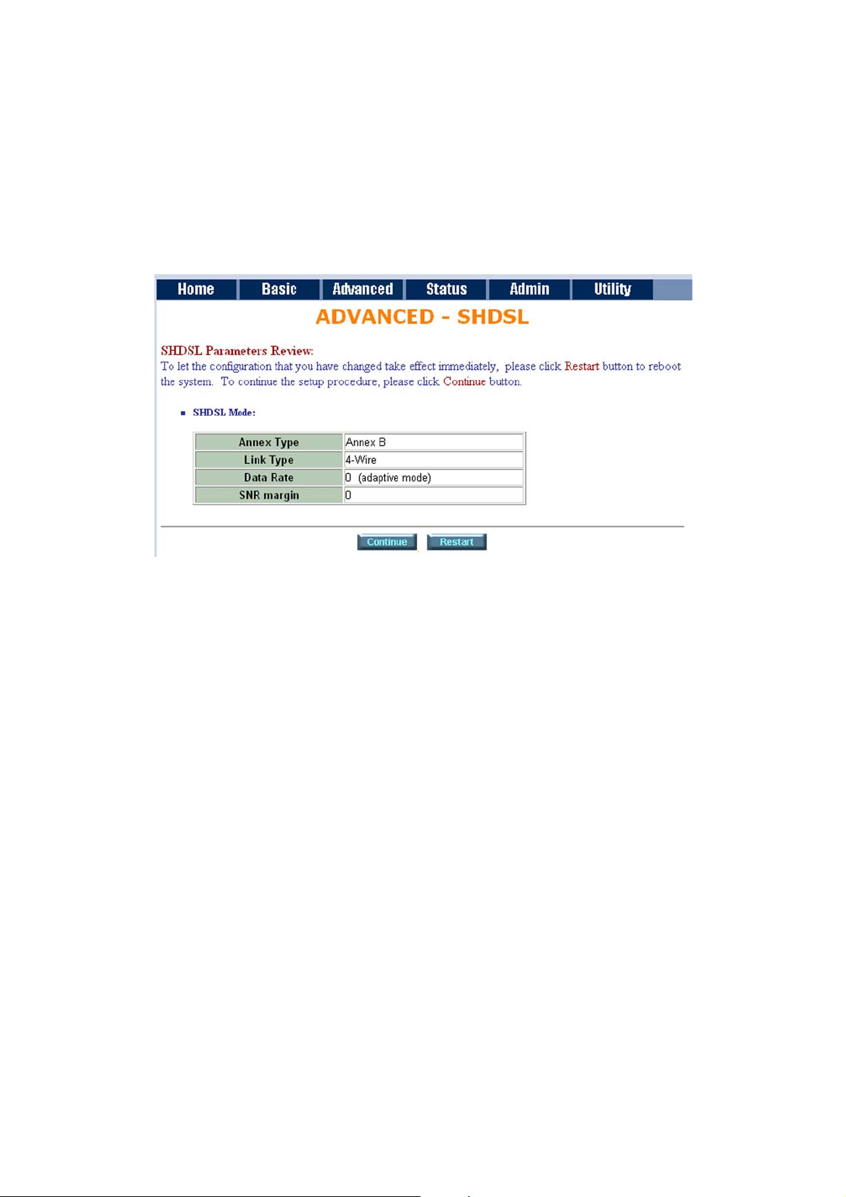
The screen will prompt the parameters that will be written in EPROM. Check the parameters before writing
in EPROM.
Press Restart to restart the modem working with new parameters or press continue to setup another
parameter.
6.52 WAN
Page 33
ATL User Guide
AM2 G.SHDSL Modem
33
6
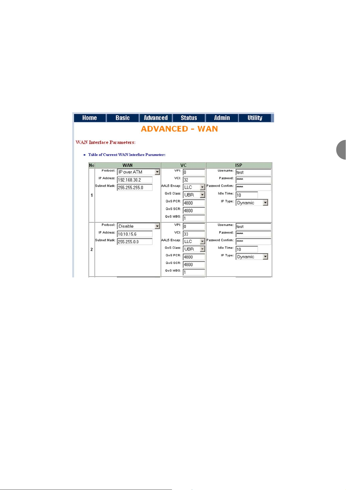
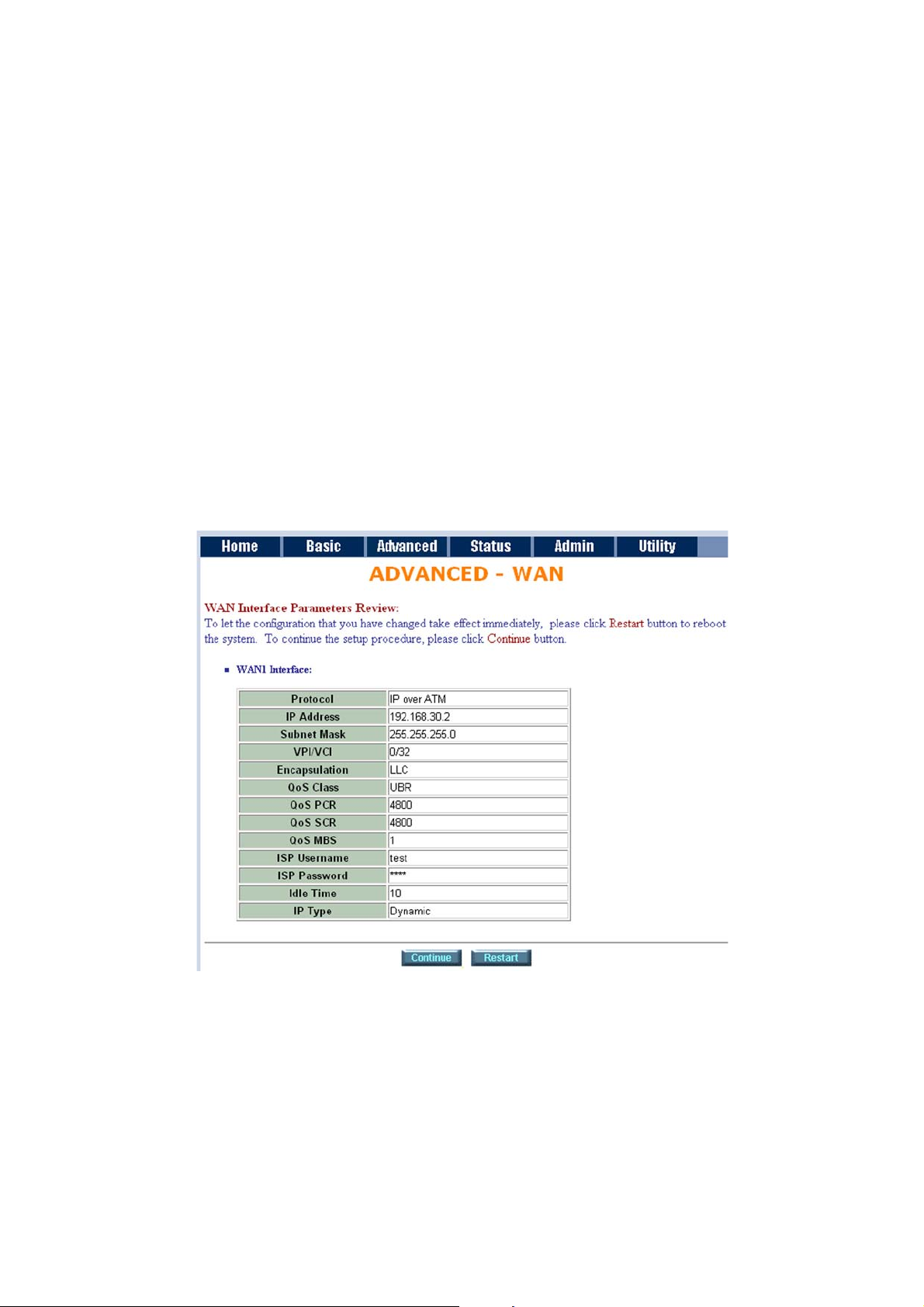
The SHDSL modem supports up to 8 PVCs. WAN 1 was configured via BASIC except for QoS. If you want to
setup PVCs, 2 to 7, the parameters are setup in WAN. On the other hand, unless two or more Internet Services
with ISPs are required you do not need to setup WAN.
The WAN Number 1 will have parameters setup in Basic Setup. If you want to setup another PVC, you can
configure them in WAN 2 to WAN 8.
Enter the parameters.
If the WAN protocol is PPPoA or PPPoE with dynamic IP, leave the default WAN IP address and Subnet Mask
as default setting. The system will ingore the IP address and Subnet mask information but deleting or leaving
blank the items will cause a system error.
If the WAN protocol is IPoA or EoA, leave the ISP parameters as default setting. The system will ignore the
information but deleting or leaving blank the items will cause system error.
QoS (Quality of Service): The Traffic Management Specification V4.0 defines ATM service catalogues that
describe both the traffic transmitted by users onto a network as well as the Quality of Service that the network
needs to provide for that traffic.
UBR (Unspecified Bit Rate) is the simplest service provided by ATM networks. There is no guarantee of
anything. It is a primary service used for transferring Internet traffic over the ATM network.
CBR (Constant Bit Rate) is used by connections that require a static amount of bandwidth that is available
during the connection life time. This bandwidth is characterized by Peak Cell Rate. Based on the PCR of the
CBR traffic, specific cell slots are assigned for the VC in the schedule table. The ATM always sends a signal
cell during the CBR connection's assigned cell slot.
VBR-rt (Varible Bit Rate real-time) is intended for real-time applications, such as compressed voice over IP and
video conferencing, that require tightly constrained delays and delay variation. VBR-rt is characterized by a
Page 34
ATL User Guide
AM2 G.SHDSL Modem
34
peak cell rate (PCR), substained cell rate (SCR), and maximum burst rate (MBR).
VBR-nrt (Varible Bit Rate non-real-time)
PCR (Peak Cell Rate) in kbps: The maximum rate at which you expect to transmit data, voice and video.
Consider PCR and MBS as a means of reducing latency, not increasing bandwidth. The range of PCR is 64kbps
to 2400kbps
SCR (Sustained Cell Rate): The sustained rate at which you expect to transmit data, voice and video. Consider
SCR to be the true bandwidth of a VC and not the lone-term average traffic rate. The range of SCR is 64kbps
to 2400kbps.
MBS (Maximum Burst Size): The amount of time or the duration at which the modem sends at PCR. The range
of MBS is 1 cell to 255 cells.
Press Finish to finish setting.
The screen will prompt the parameters that will be written in EPROM. Check the parameters before writing
in EPROM.
Press Restart to restart the modem working with new parameters or press continue to setup another
parameter
.
6.5.3 BRIDGE
Page 35
ATL User Guide
AM2 G.SHDSL Modem
35
6
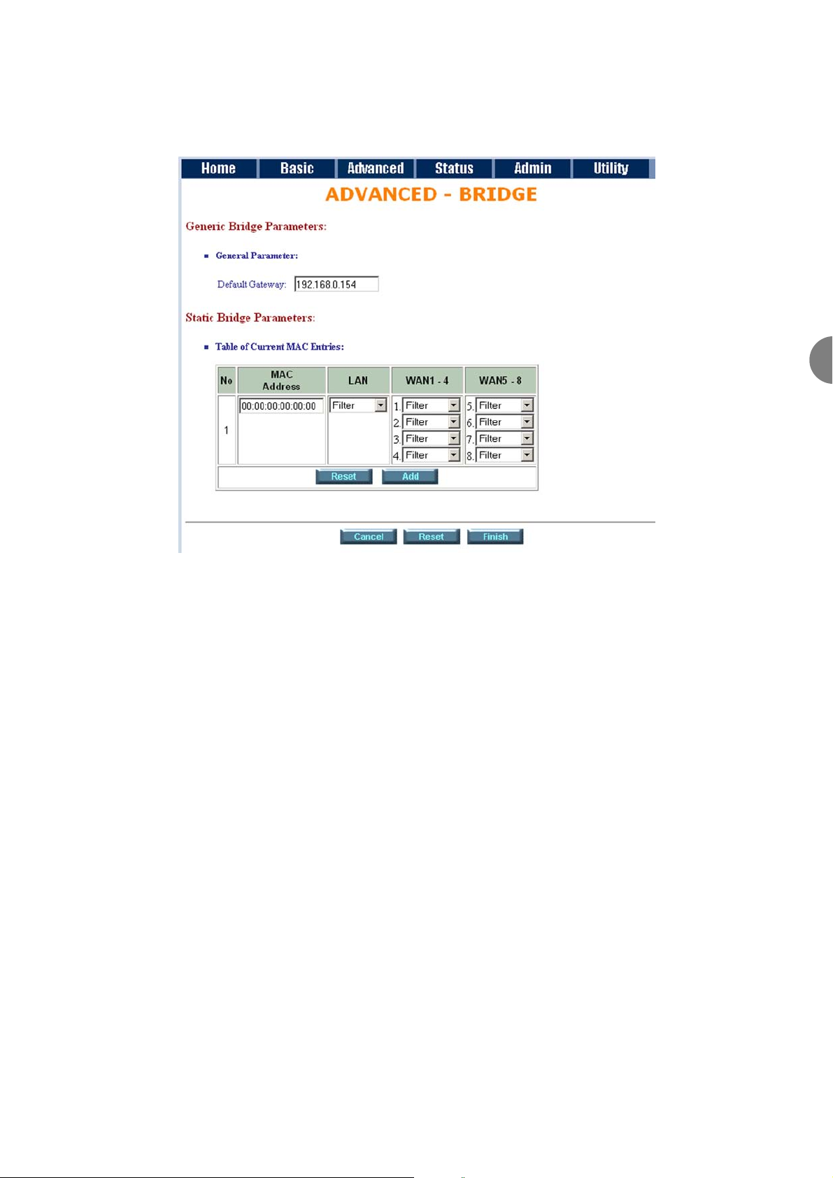
If your modem is setup in bridge mode and you want to setup advanced filter function, you can use BRIDGE
menu to setup the filter function, blocking function.
Click Bridge to setup.
Press Add to add the static bridge information.
If you want to filter the definite MAC address of LAN PC to access the Internet, press Add to establish the
filtering table. Key the MAC address in MAC address field and select Filter in LAN field.
If you want to filter the definite MAC address of WAN PC to access the LAN, press Add to establish the
filtering table. Key the MAC address in MAC address field and select Filter in WAN field. For example: if your
VC is setup at WAN 1, select WAN 1 Filter.
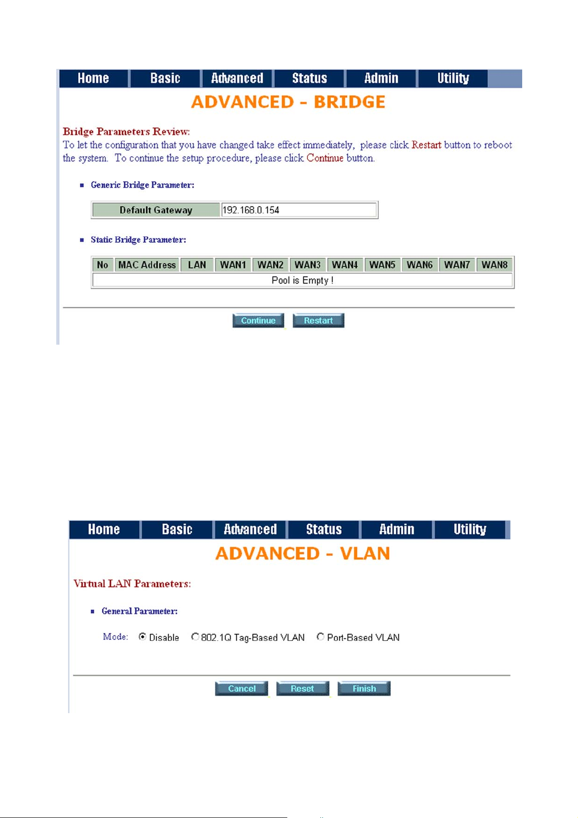
The screen will prompt the parameters that will be written in EPROM. Check the parameters before writing
in EPROM.
Page 36
ATL User Guide
AM2 G.SHDSL Modem
36
Press Restart to restart the modem working with new parameters or press continue to setup another
parameter.
6.5.4 VLAN
Virtual LAN (VLAN) is defined as a group of devices on one or more LANs that are configured so that they can
communicate as if they were attached to the same wire, when in fact they are located on a number of
different LAN segments. Because VLAN is based on logical instead of physical connections, it is extremely
flexible.
Click VLAN to configure VLAN.
The product supports two types of VLAN, 802.1Q and Port-Based. The user can configure one of them on the
modem.
Page 37
ATL User Guide
AM2 G.SHDSL Modem
37
6
6.5.4.1 802.1Q VLAN
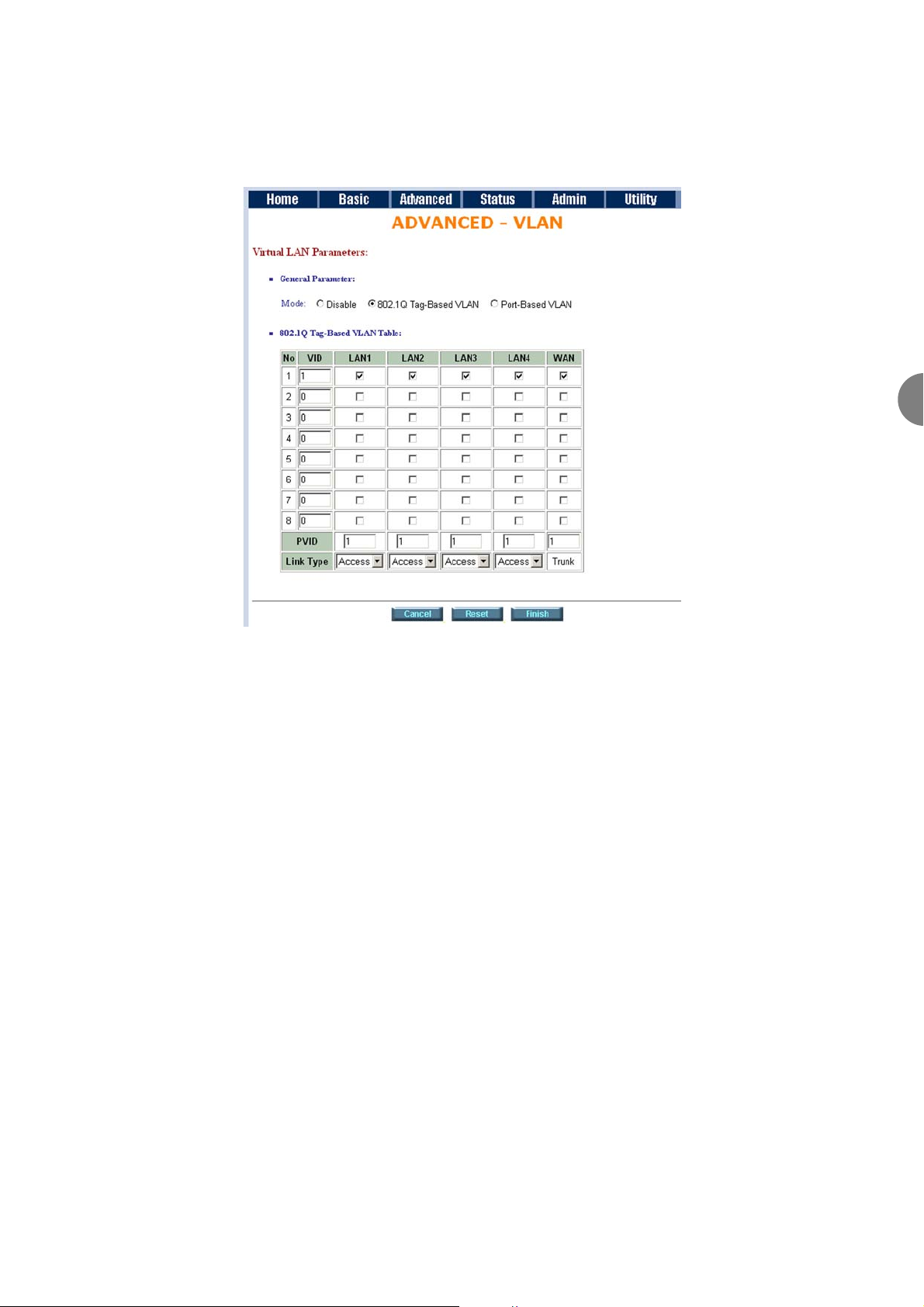
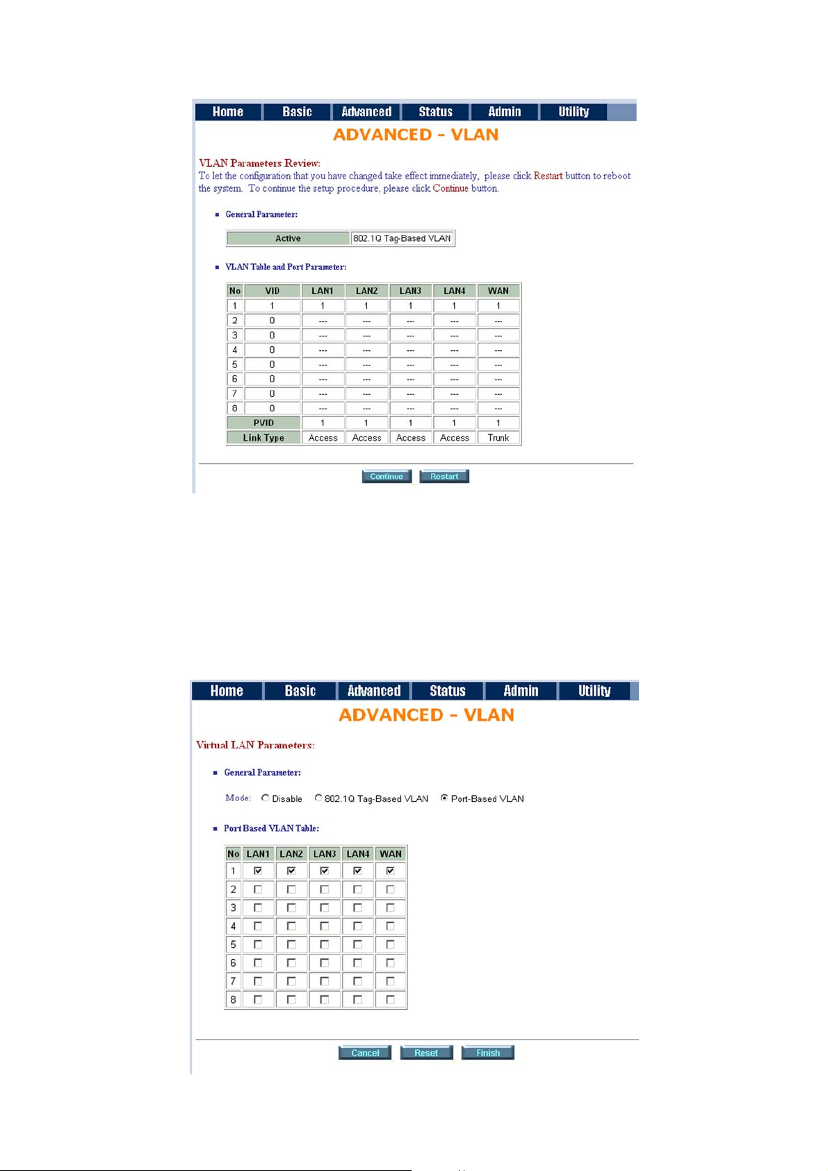
For setting 802.1Q VLAN click the 802.1Q Tag-Based VLAN. The screen will prompt as follow.
VID: Virtual LAN ID. It is a definite number of ID from 1 to 4094.
PVID: Port VID which is an untagged member of default VLAN.
Link Type: Access means the port can receive or send untagged packets.
Link Type: Trunk means that the port can receive or send tagged packets.
Page 38
ATL User Guide
AM2 G.SHDSL Modem
38
6.5.4.1 PORT-BASED VLAN
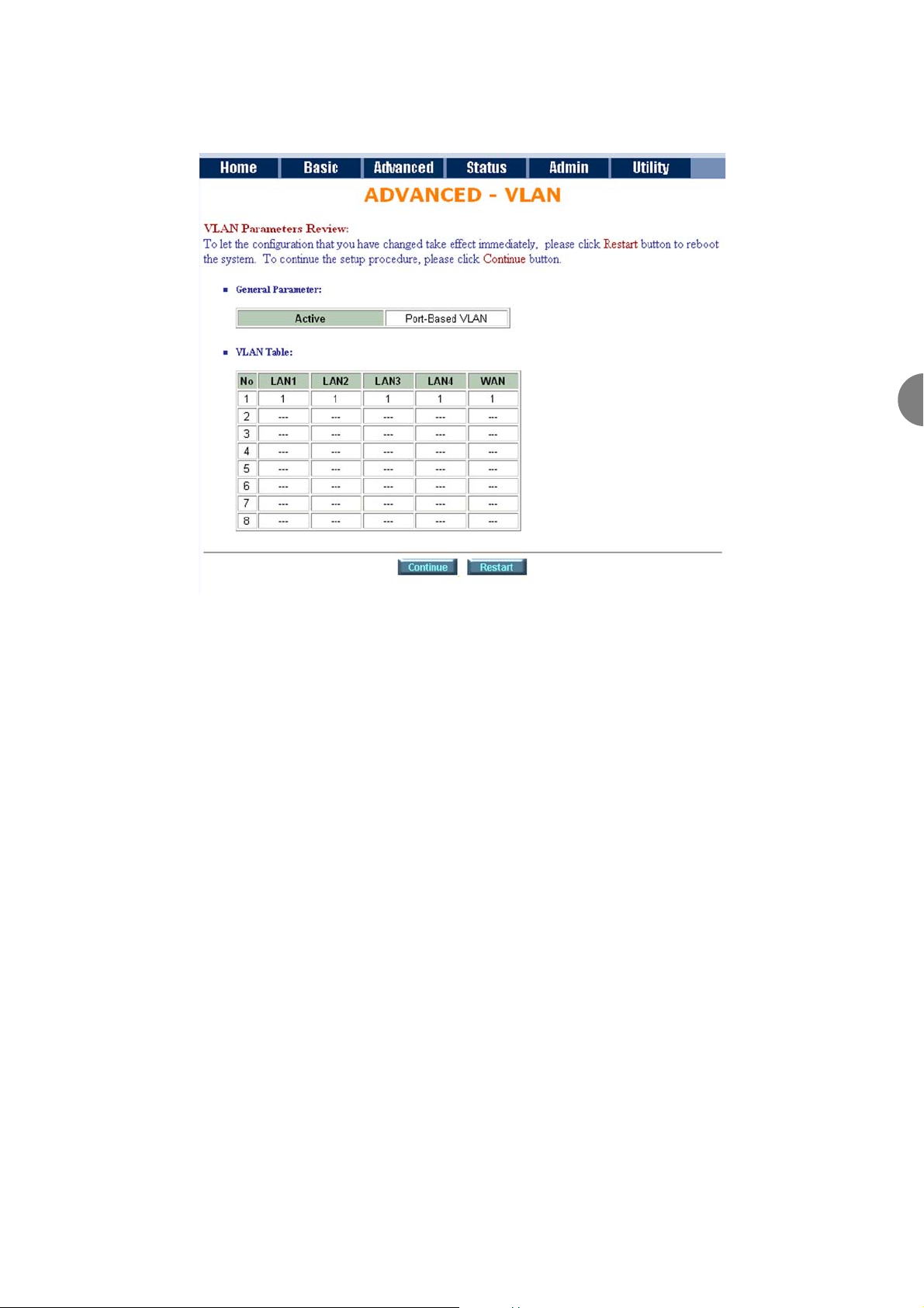
Port-Based VLANs are VLANs where the packet forwarding decision is based on the destination MAC address
and its associated port.
Click Port-Based VLAN to configure the modem.
Page 39
ATL User Guide
AM2 G.SHDSL Modem
39
6
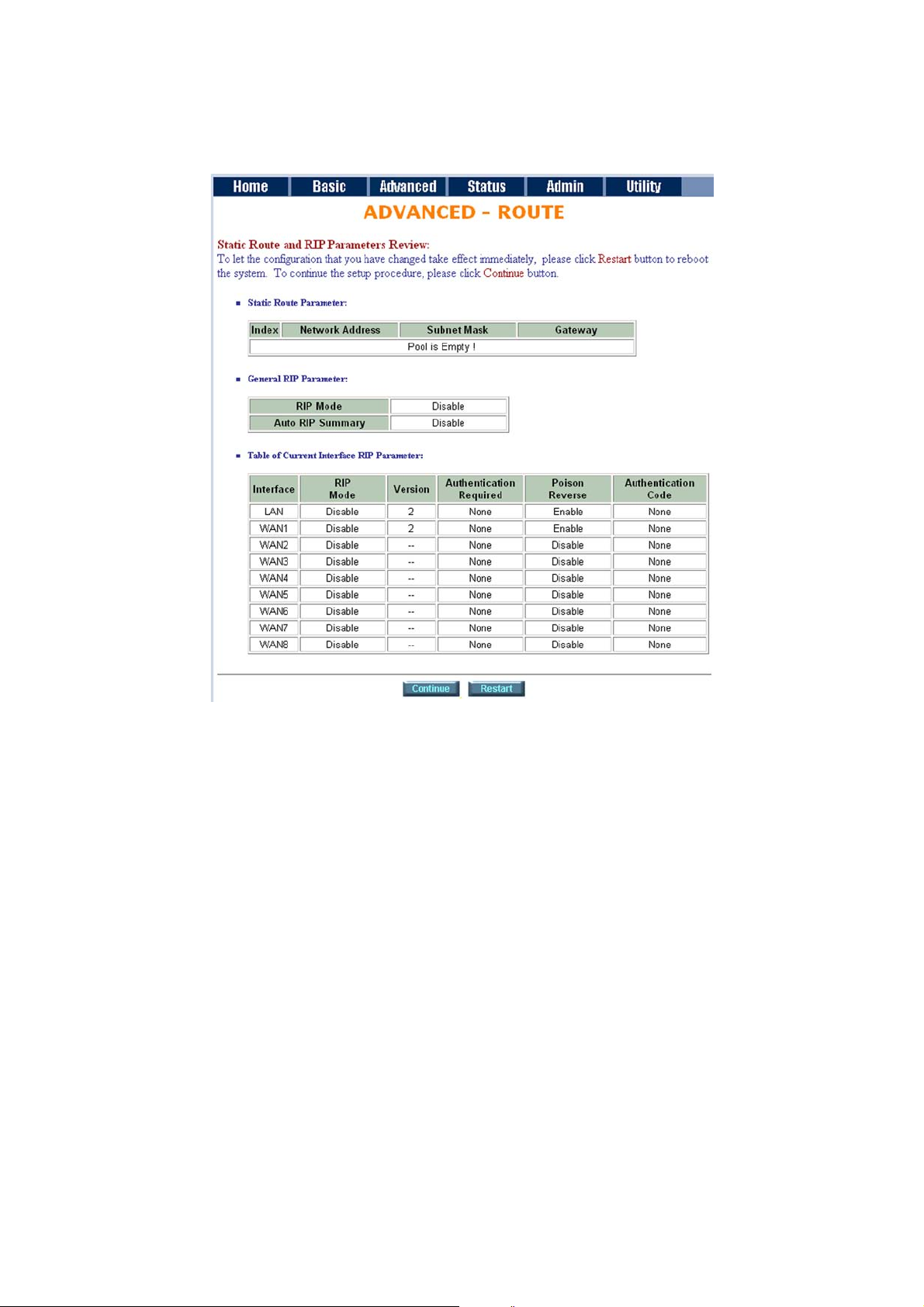
6.5.5 ROUTE
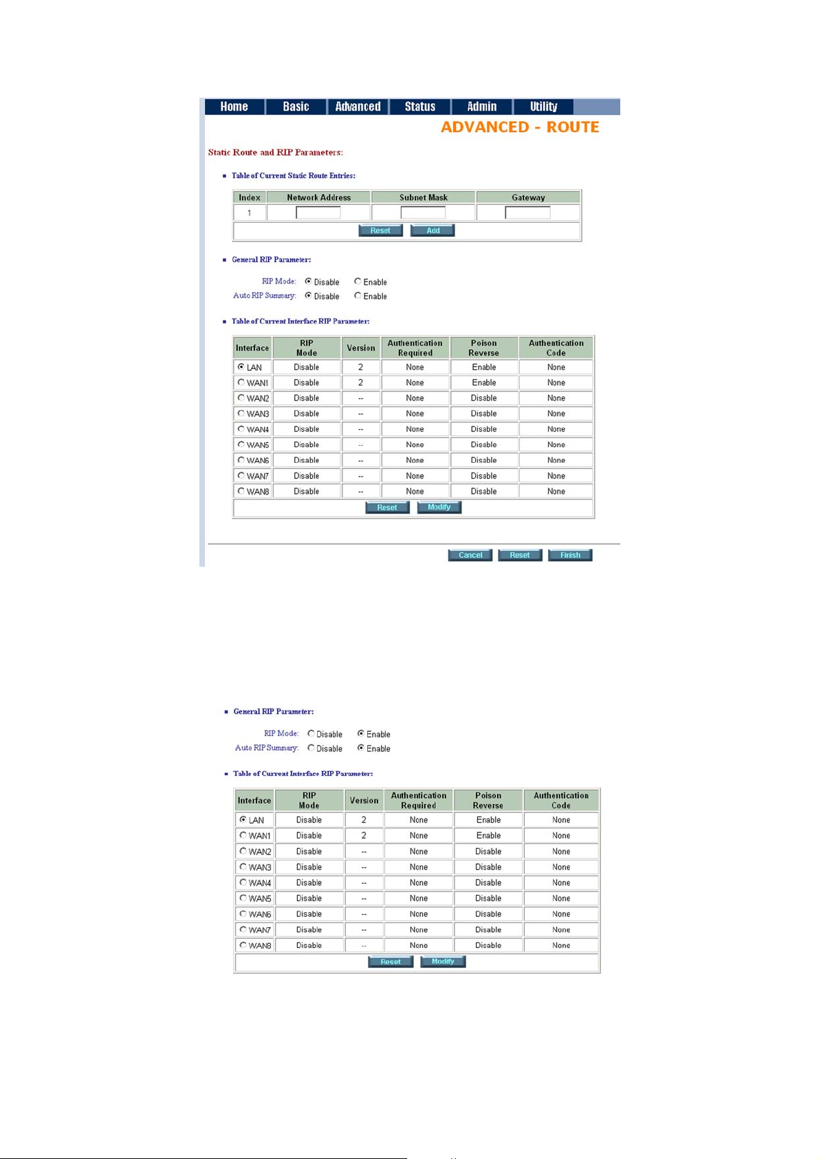
If the modem is connected to more than one network, it may be necessary to set up a static route between
them. A static route is a pre-determined pathway that network information must travel to reach a specific
host or network.
With Dynamic Routing, you can enable the router function in the modem to automatically adjust to physical
changes in the network's layout. The router function, using the RIP protocol, determines the network packets'
route based on the fewest number of hops between the source and the destination. The RIP protocol regularly
broadcasts routing information to other routers on the network.
Click Route to modify the routing information.
Page 40
ATL User Guide
AM2 G.SHDSL Modem
40
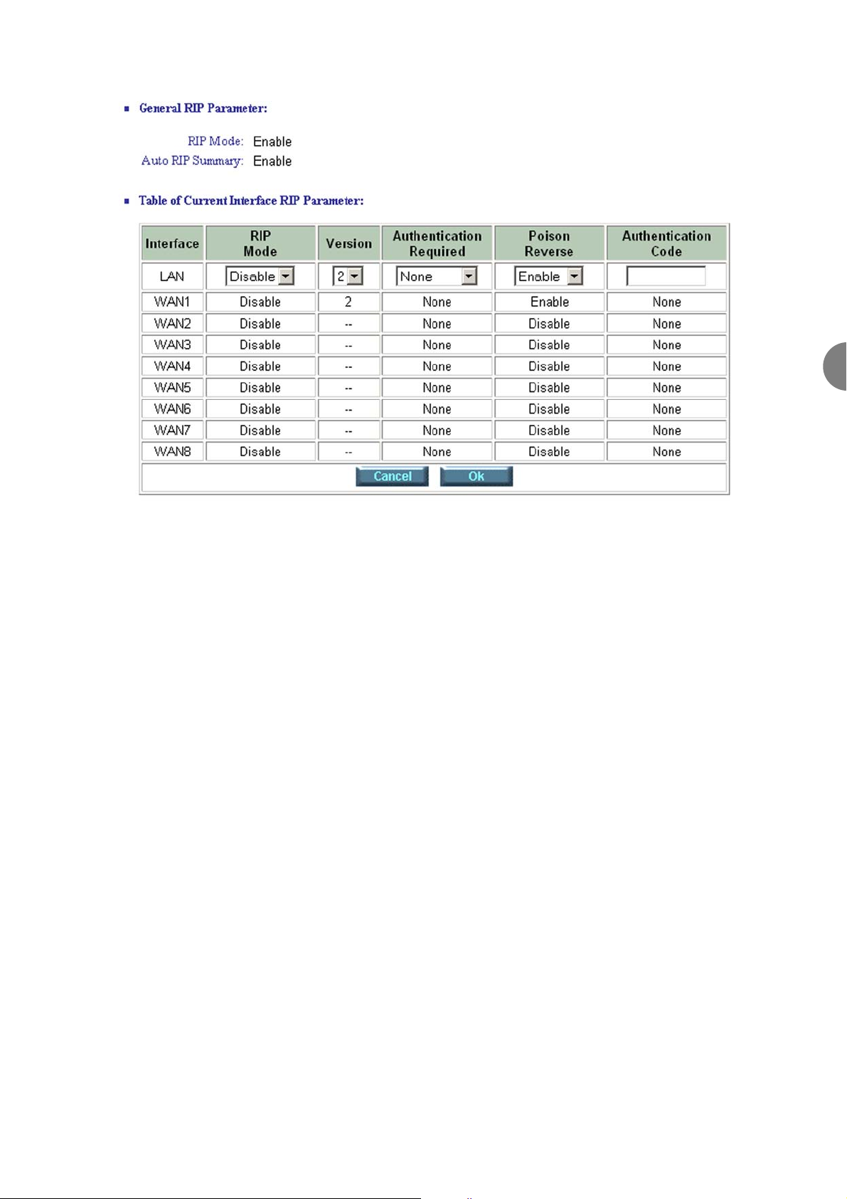
To modify the RIP (Routing information protocol) Parameters:
RIP Mode: Enable
Auto RIP Summary: Enable
Press Modify
Page 41
ATL User Guide
AM2 G.SHDSL Modem
41
6
RIP Mode: this parameter determines how the product handles RIP (Routing information protocol). RIP allows
it to exchange routing information with other routers. If set to Disable, the modem does not participate in
any RIP exchange with other routers. If set to Enable, the router function in the modem broadcasts its routing
table on the LAN and incorporates RIP broadcasts by other routers into it's routing table. If set to Silent, the
modem does not broadcast the routing table, but it accepts RIP broadcast packets that it receives.
RIP Version: It determines the format and broadcasting method of any RIP transmissions by the gateway.
RIP v1: it only sends RIP v1 messages only.
RIP v2: it send RIP v2 messages in multicast and broadcast format.
Authentication required.
None: for RIP, there is no need of authentication code.
Password: the RIP is protected by password, authentication code.
MD5: The RIP will be decoded by MD5 then protected by password, authentication code.
Poison Reserve is for the purpose of promptly broadcast or multicast the RIP while the route is changed. (ex
shutting down one of the routers in routing table)
Enable: the gateway will actively broadcast or multicast the information.
Disable: the gateway will not broadcast or multicast the information.
After modifying the RIP parameters, press OK.
Page 42
ATL User Guide
AM2 G.SHDSL Modem
42
The screen will prompt the modified parameter. Check the parameters and press Restart to restart the modem
or press Continue to setup another parameter.
6.5.6 NAT/DMZ
NAT (Network Address Translation) is the translation of an Internet Protocol address (IP address) used within
one network to a different IP address known within another network. One network is designated the inside
network and the other is the outside. Typically, a company maps its local inside network addresses to one or
more global outside IP addresses and reverses the global IP addresses of incoming packets back into local IP
addresses. This ensures security since each outgoing or incoming request must go through a translation
process, that also offers the opportunity to qualify or authenticate the request or match it to a previous
request. NAT also conserves the number of global IP addresses that a company needs and lets the company
use a single IP address for communication in the Internet world.
DMZ (demilitarized zone) is a computer host or small network inserted as a "neutral zone" between a
company private network and the outside public network. It prevents outside users from getting direct access
to a server that has company private data.
In a typical DMZ configuration for an enterprise, a separate computer or host receives requests from users
within the private network to access via Web sites or other companies accessible on the public network. The
DMZ host then initiates sessions for these requests to the public network. However, the DMZ host is not able
to initiate a session back into the private network. It can only forward packets that have already been
requested.
Page 43
ATL User Guide
AM2 G.SHDSL Modem
43
6
Users of the public network outside the company can only access the DMZ host. The DMZ may typically also
have the company's Web pages so these could serve the outside world. However, the DMZ provides access
to no other company data. In the event that an outside user penetrated the DMZ host's security, the Web
pages might be corrupted, but no other company information would be exposed.
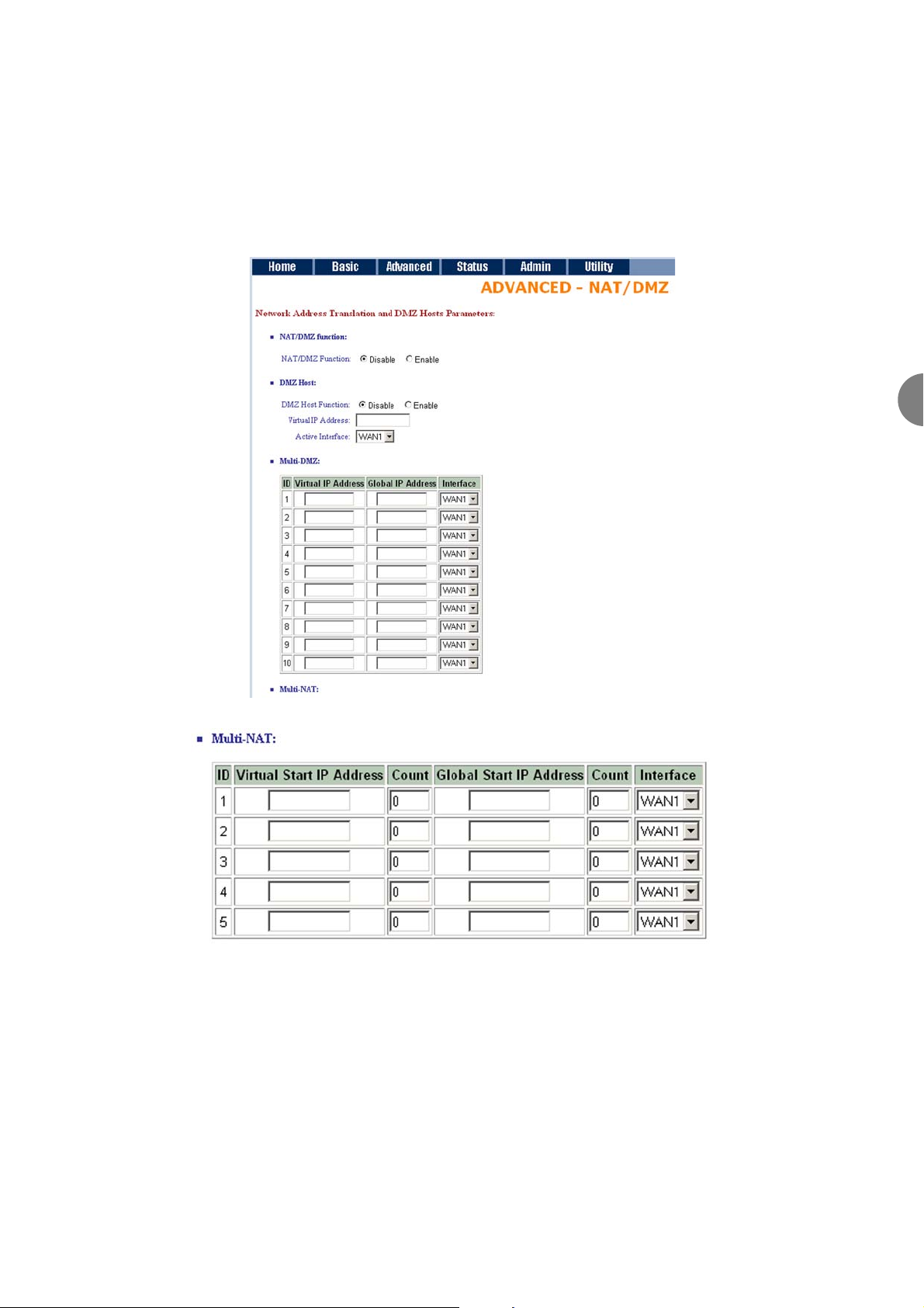
Press NAT/DMZ to setup the parameters.
If you want to enable the NAT/DMZ functions, click Enable. Enable the DMZ host Function uses the IP address
assigned to the WAN for enabling DMZ function for the virtual IP address.
Multi-DMZ: Some users who have two or more global IP addresses assigned by ISPs can use the multi DMZ.
The table is for the mapping of global IP address and virtual IP address.
Multi-NAT: Some of the virtual IP addresses (eg: 192.168.0.10 ~ 192.168.0.50) collectively use two of the
global IP addresses (eg: 69.210.1.9 and 69.210.1.10). The Multi-NAT table will be setup as;
Virtual Start IP Address: 192.168.0.10
Page 44
ATL User Guide
AM2 G.SHDSL Modem
44
Count: 40
Global Start IP Address: 69.210.1.9
Count: 2
Press Finish to continue.
The screen will prompt for parameters that will be written in EPROM. Check the parameters before writing in
EPROM. Press Restart to restart the modem working with new parameters or Continue to configure another
parameter.
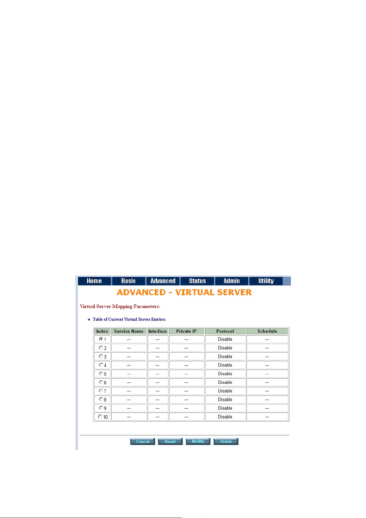
6.5.6 VIRTUAL SERVER
For example: Specific ports on the WAN interface are re-mapped to services inside the LAN. As only
69.210.1.8 (e.g., assigned to WAN from ISP) is visible to the Internet, but does not actually have any services
(other than NAT of course) running on the gateway, it is said to be a virtual server. Request with TCP made
to 69.210.1.8:80 are remapped to the server 1 on 192.168.0.2:80 for working days from Monday to Friday
8 AM to 6PM, other requests with UDP made to 69.210.1.8:25 are remapped to server 2 on 192.168.0.3:25
and always on.
You can setup the modem as Index 1, protocol TCP, interface WAN1, service name test1, private IP
192.168.0.2, private port 80, public port 80, schedule from Day Monday to Friday and time 8:0 to 16:0 and
index 2, protocol UDP, interface WAN1, service name test2, private IP 192.168.0.3, private port 25, public port
25, schedule always.
Click Virtual Server to configure the parameters.
Page 45

ATL User Guide
AM2 G.SHDSL Modem
45
6
Press Modify for modify 1.
Type the necessary parameters then click Finish.
Press Restart to restart the modem or press continue to setup another function.
Page 46

ATL User Guide
AM2 G.SHDSL Modem
46
6.5.7 FIREWALL
A firewall protects networked computers from intentional hostile intrusion that could compromise
confidentiality or result in data corruption or denial of service. It must have at least two network interfaces,
one for the network it is intended to protect, and one for the network it is exposed to. A firewall sits at the
junction point or gateway between the two networks, usually a private network and a public network such
as the Internet.
A firewall examines all traffic routed between the two networks to see if it meets certain criteria. If it does, it
is routed between the networks, otherwise it is stopped. A firewall filters both inbound and outbound traffic.
It can also manage public access to private networked resources such as host applications. It can be used to
log all attempts to enter the private network and trigger alarms when hostile or unauthorized entry is
attempted. Firewalls can filter packets based on their source and destination addresses and port numbers. This
is known as address filtering. Firewalls can also filter specific types of network traffic. This is also known as
protocol filtering because the decision to forward or reject traffic is dependant upon the protocol used, for
example HTTP, ftp or telnet. Firewalls can also filter traffic by packet attribute or state.
An Internet firewall cannot prevent individual users with modems from dialling into or out of the network. By
doing so they bypass the firewall altogether. Employee misconduct or carelessness cannot be controlled by
firewalls. Policies involving the use and misuse of passwords and user accounts must be strictly enforced.
These are management issues that should be raised during the planning of any security policy, but that cannot
be solved with Internet firewalls alone.
A firewall is a set of related programs that protects the resources of a private network from other networks.
It is helpful to users preventing hackers from accessing its own private data resource accidentally.
Page 47
ATL User Guide
AM2 G.SHDSL Modem
47
6
6.5.7.1 BASIC FIREWALL SECURITY
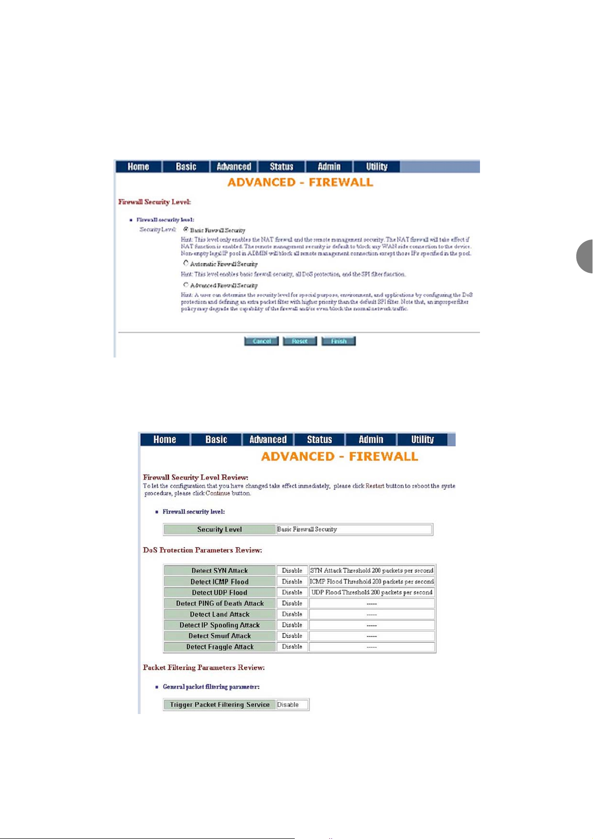
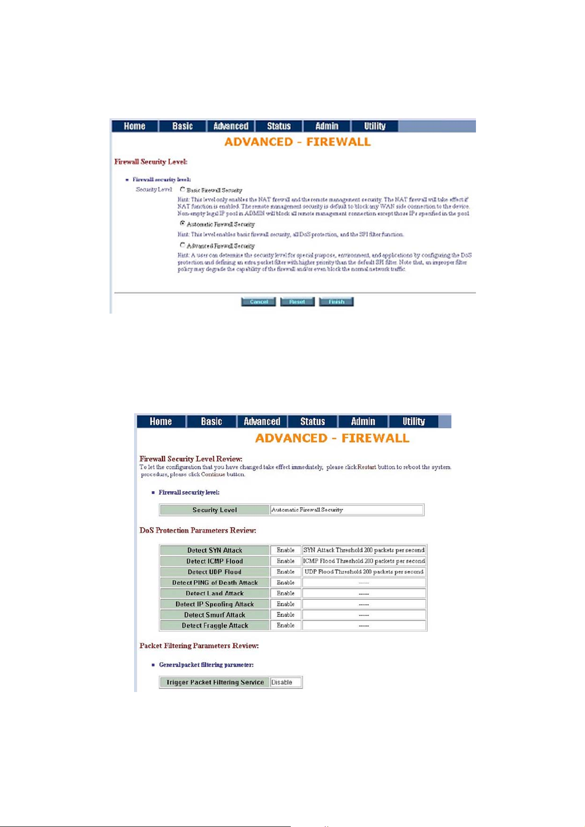
This level only enables the NAT firewall and the remote management security. The NAT firewall will take effect
if NAT function is enabled. The remote management security is default to block any WAN side connection to
the device. Non-empty legal IP pool in ADMIN will block all remote management connections except those
IPs specified in the pool.
Press Finish to finish setting of the firewall
The screen will prompt for parameters, which will be written in EPROM. Check the parameters.
Press restart to restart the modem or press continue to setup another function.
Page 48
ATL User Guide
AM2 G.SHDSL Modem
48
6.5.7.2 AUTOMATIC FIREWALL SECURITY
This level enables basic firewall security, all DoS protection, and the SPI filter function.
Press Finsih to finish setting firewall.
The screen will prompt the parameters, which will be written in EPROM. Check the parameters.
Press restart to restart the modem or press Continue to setup another function.
Page 49
ATL User Guide
AM2 G.SHDSL Modem
49
6
6.5.7.3 ADVANCED FIREWALL SECURITY
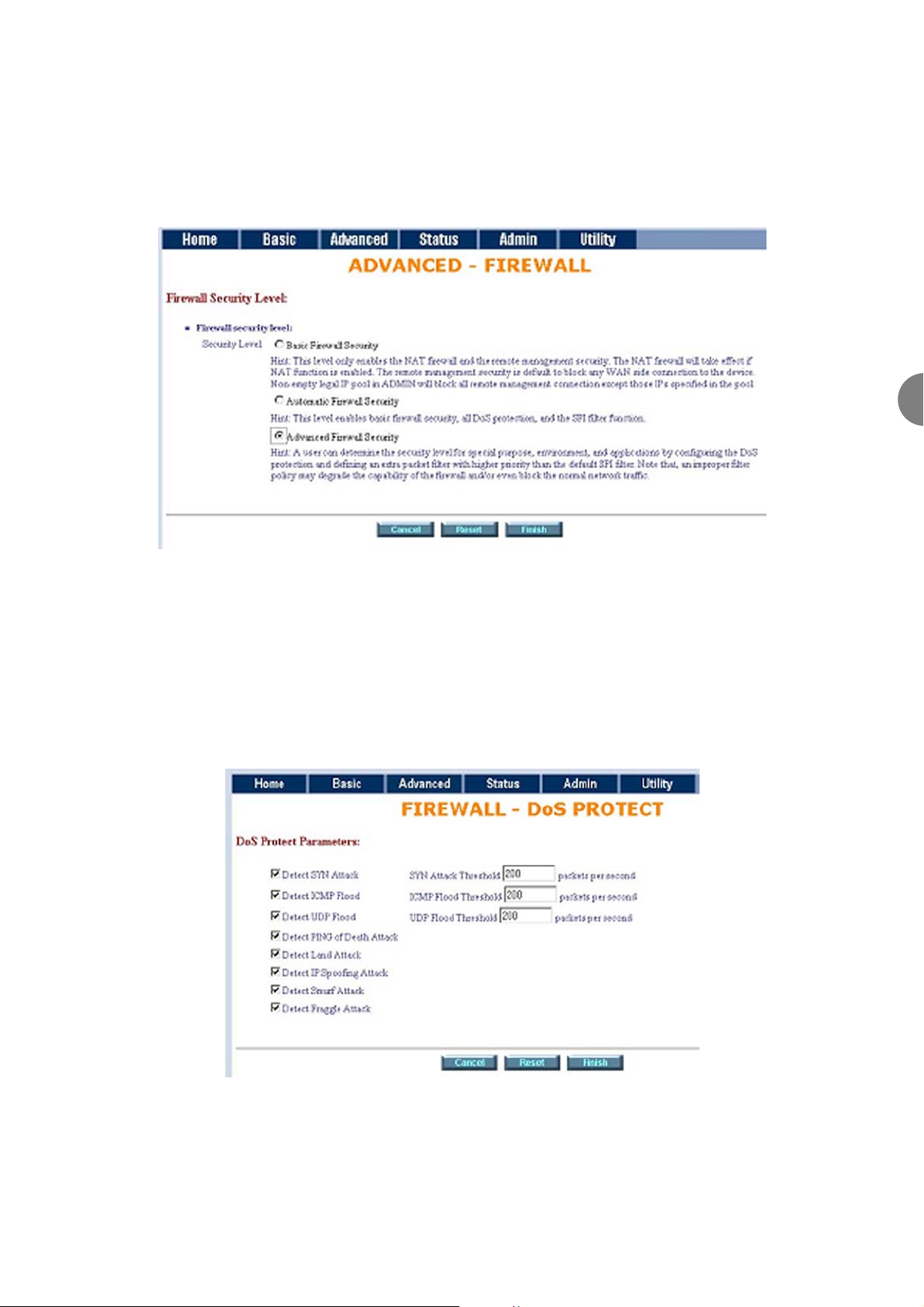
The user can determine the security level for special purposes, environments, and applications by configuring
the DoS protection and defining an extra packet filter with higher priority than the default SPI filter. Note that
an improper filter policy may degrade the capability of the firewall and/or even block normal network traffic.
Click Advanced Firewall Security and then press Finish.
A SYN flood attack attempts to slow your network by requesting new connections but not completing the
process to open the connection. Once the buffer for these pending connections is full a server will not accept
any more connections and will be unresponsive.
ICMP Flood: A sender transmits a volume of ICMP request packets to cause all CPU resources to be consumed
serving the phony requests.
UDP Flood: A sender transmits a volume of requests for UDP diagnostic services which cause all CPU resources
to be consumed serving the phony requests.
Page 50
ATL User Guide
AM2 G.SHDSL Modem
50
A ping of death attack attempts to crash your system by sending a fragmented packet, which when
reconstructed is larger than the maximum allowable size. Other known variants of the ping of death include
teardrop, bonk and nestea.
A land attack is an attempt to slow your network down by sending a packet with identical source and
destination addresses originating from your network.
IP Spoofing is a method of masking the identity of an intrusion by making it appeared that the traffic came
from a different computer. This is used by intruders to keep their anonymity and can be used in a Denial of
Service attack.
A smurf attack involves two systems. The attacker sends a packet containing a ICMP echo request (ping) to
the network address of one system. This system is known as the amplifier. The return address of the ping has
been faked (spoofed) to appear to come from a machine on another network (the victim). The victim is then
flooded with responses to the ping. As many responses are generated for only one attack, the attacker is able
use many amplifiers on the same victim.
IP Spoofing: Falsify the IP header information to deceive the destination host.
Traditional firewalls are stateless meaning they have no memory of the connections of data or packets that
pass through them. Such IP filtering firewalls simply examine header information in each packet and attempt
to match it to a set of defined rules. If the firewall finds a match, the prescribed action is taken. If no match
is found, the packet is accepted into the network, or dropped, depending on the firewall configuration.
A stateful firewall maintains a memory of each connection and data passing through it. Stateful firewalls
record the context of connections during each session, continuously updating state information in dynamic
tables. With this information, stateful firewalls inspect each connection traversing each interface of the
firewall, testing the validity of data packets throughout each session. As data arrives, it is checked against the
state tables and if the data is part of the session, it is accepted. Stateful firewalls enable a more intelligent,
flexible and robust approach to network security, while defeating most intrusion methods that exploit stateless IP filtering firewalls.
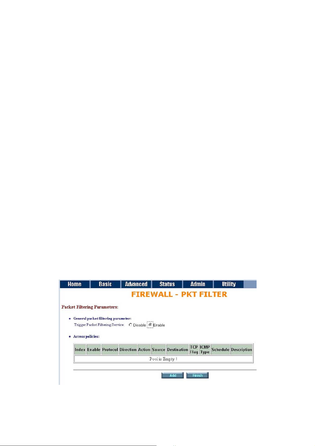
If you want to configure the Packet Filtering Parameters, choose Enable and press Add.
Select the protocol and configure the parameter.
Page 51
ATL User Guide
AM2 G.SHDSL Modem
51
6
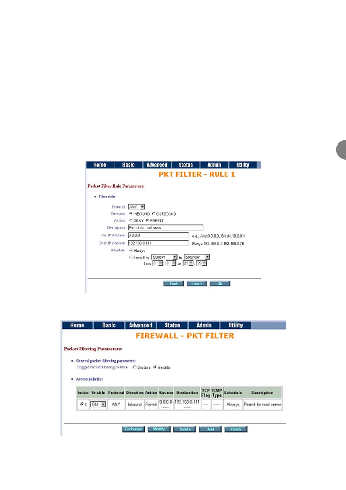
If you want to ban all the protocols from the an IP address (e.g.: 200.1.1.1) form accessing all the PCs (e.g.:
192.168.0.2 ~ 192.168.0.50) in the LAN, key in the parameter as;
Protocol: ANY
Direction: INBOUND (INBOUND is from WAN to LAN, and OUTBOUND is LAN to WAN.)
Description: Hacker
Src. IP Address: 200.1.1.1
Dest. IP Address: 192.168.0.2-192.168.0.50
Press OK to finish.
The screen will prompt the configured parameters. Check the parameters.
Click Restart to restart the gateway or Continue to configure another parameters.
Page 52
ATL User Guide
AM2 G.SHDSL Modem
52
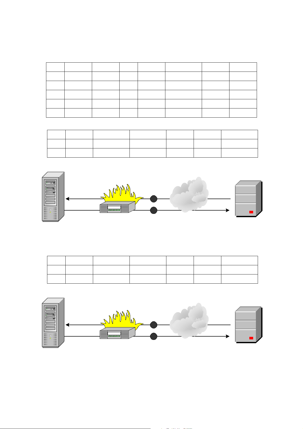
6.5.7.4FILTERING RULE FOR SMTP CONNECTION
Filtering rules are configured as follows:
Internet
Packet Source Action (Rule)Direction Protocol Dest. PortDestination
25192.168.3.4172.16.1.1 Permit (C)Outbound TCP3
1357172.16.1.1192.168.3.4 Permit (D)Inbound TCP4
SMTP Client
SMTP Server
3
4
Firewall
172.16.1.1:1357
192.168.3.4:25
Internet
Packet Source Action (Rule)Direction Protocol Dest. PortDestination
25172.16.1.1192.168.3.4 Permit (A)Inbound TCP1
1234192.168.3.4172.16.1.1 Permit (B)Outbound TCP2
SMTP Server
SMTP Client
1
2
Firewall
172.16.1.1:25
192.168.3.4:1234
Index SourceActionDirectionProtocol ScheduleDest. PortDestination
25InternalExternalPermitInboundTCP1 Always
>1023ExternalInternalPermitOutboundTCP2 Always
25ExternalInternalPermitOutboundTCP3 Always
>1023InternalExternalPermitInboundTCP4 Always
25AnyAnyDenyEitherAny5 Always
Page 53
ATL User Guide
AM2 G.SHDSL Modem
53
6
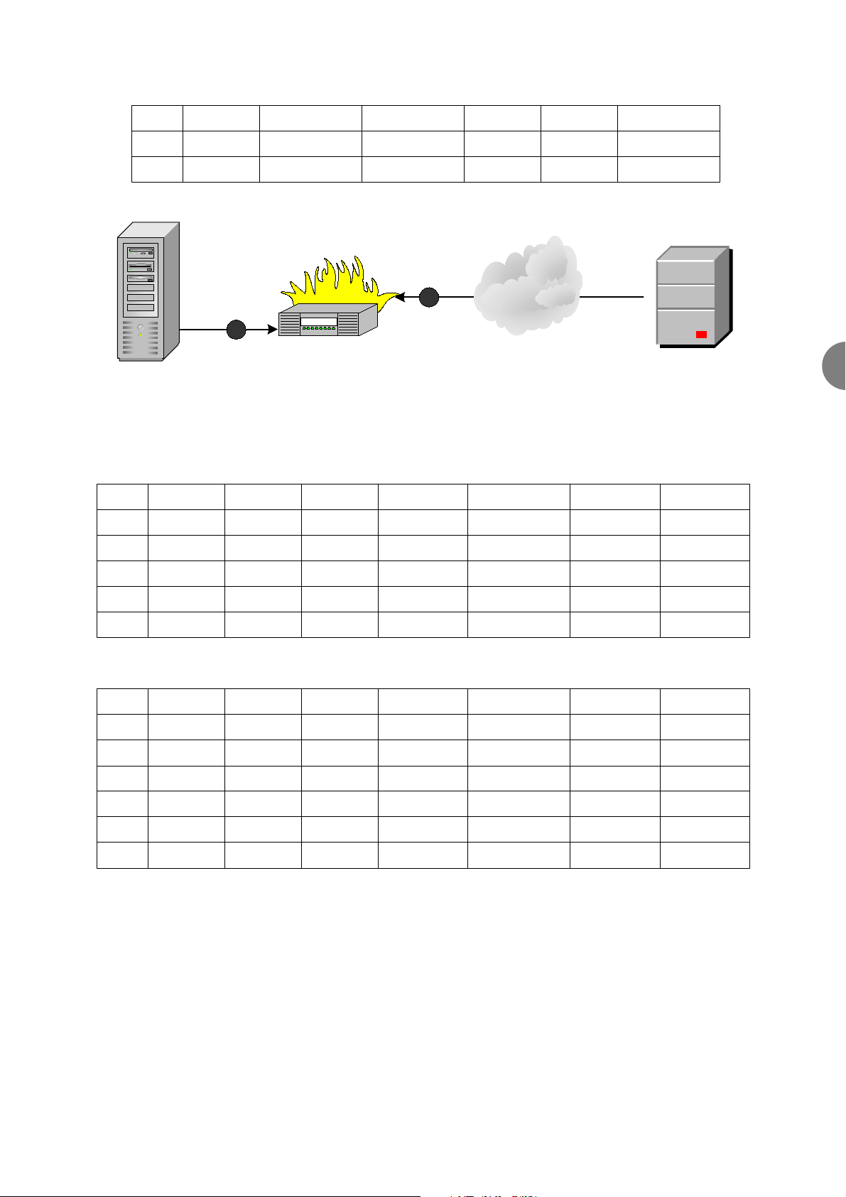
Index SourceActionDirectionProtocol Source. PortDestination
1234171.16.1.1192.168.3.4Permit (A)InboundTCP1
25192.168.3.4171.16.1.1Permit (B)OutboundTCP2
1357192.168.3.4171.16.1.1Permit (C)OutboundTCP3
25171.16.1.1192.168.3.4Permit (D)InboundTCP4
5150171.16.3.410.1.2.3Permit (E)InboundTCP5
600010.1.2.3171.16.3.4Permit (E)OutboundTCP6
Dest. Port
25
1234
25
1357
6000
5150
Index SourceActionDirectionProtocol Source. PortDestination
>1023InternalExternalPermitInboundTCP1
25ExternalInternalPermitOutboundTCP2
>1023ExternalInternalPermitOutboundTCP3
25InternalExternalPermitInboundTCP4
AnyAnyAnyDenyEitherAny5
Dest. Port
25
>1023
25
>1023
25
Update Filtering Rule
Filtering Result
Internet
Packet Source Action (Rule)Direction Protocol Dest. PortDestination
6000171.16.3.410.1.2.3 Deny (E)Inbound TCP5
515010.1.2.3171.16.3.4 Deny (E)Outbound TCP6
X11 Server
Attacker
5
6
Firewall
172.16.3.4:6000
10.1.2.3:5150
Page 54

ATL User Guide
AM2 G.SHDSL Modem
54
Rule Order
The rules order affects the filtering result. The filtering process proceeds from top to bottom, changing the
order based on the results of filtering.
Where "0" at the last eight bits indicates "from 1 to 254", "0" at any eight bits preceding "0", "0.0" or
"0.0.0" indicates "from 1 to 254". On the other hand, "0" and all "0" successive with "0" represents any.
When the rule is ordered as ABC.
The rule order will permit 10.1.99.1 to access 172.16.6.1.
When the rule is ordered as BAC.
The rule order will deny 10.1.99.1 to access 172.6.6.1.
Rule Source Address Action
Deny (B)10.1.99.11
Deny (B)10.1.99.12
Permit (A)10.1.1.13
Destination Address
172.16.1.1
172.16.6.1
172.16.6.1
Deny (C)10.1.99.14
Deny (C)192.168.3.45
172.16.1.1
172.16.6.1
Rule Source Address Action
Deny (B)10.1.99.11
Permit (A)10.1.99.12
Permit (A)10.1.1.13
Destination Address
172.16.1.1
172.16.6.1
172.16.6.1
Deny (C)10.1.99.14
Deny (C)192.168.3.45
172.16.1.1
172.16.6.1
Rule Source Address Action
Permit10.0.0.0A
Deny10.1.99.0B
DenyAnyC
Destination Address
172.16.6.0
172.16.0.0
Any
Page 55
ATL User Guide
AM2 G.SHDSL Modem
55
6
6.6 STATUS
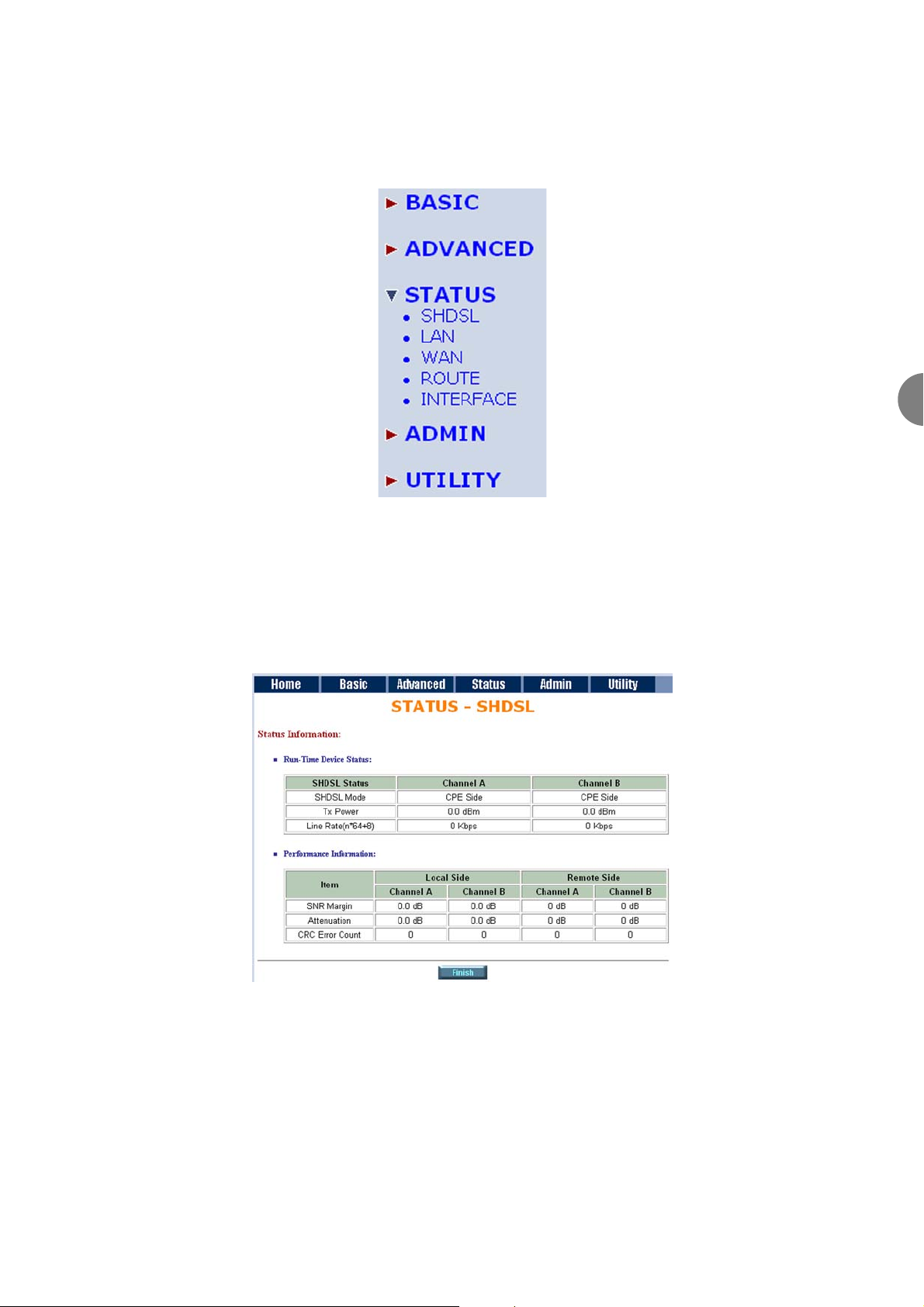
The Status menu allows you to view the current status and setup of the AM2.
6.6.1 SHDSL
You can monitor the SHDSL status including mode, Tx power, Bitrate and Performance information including
SNR margin, attenuation and CRC error count.
Page 56
ATL User Guide
AM2 G.SHDSL Modem
56
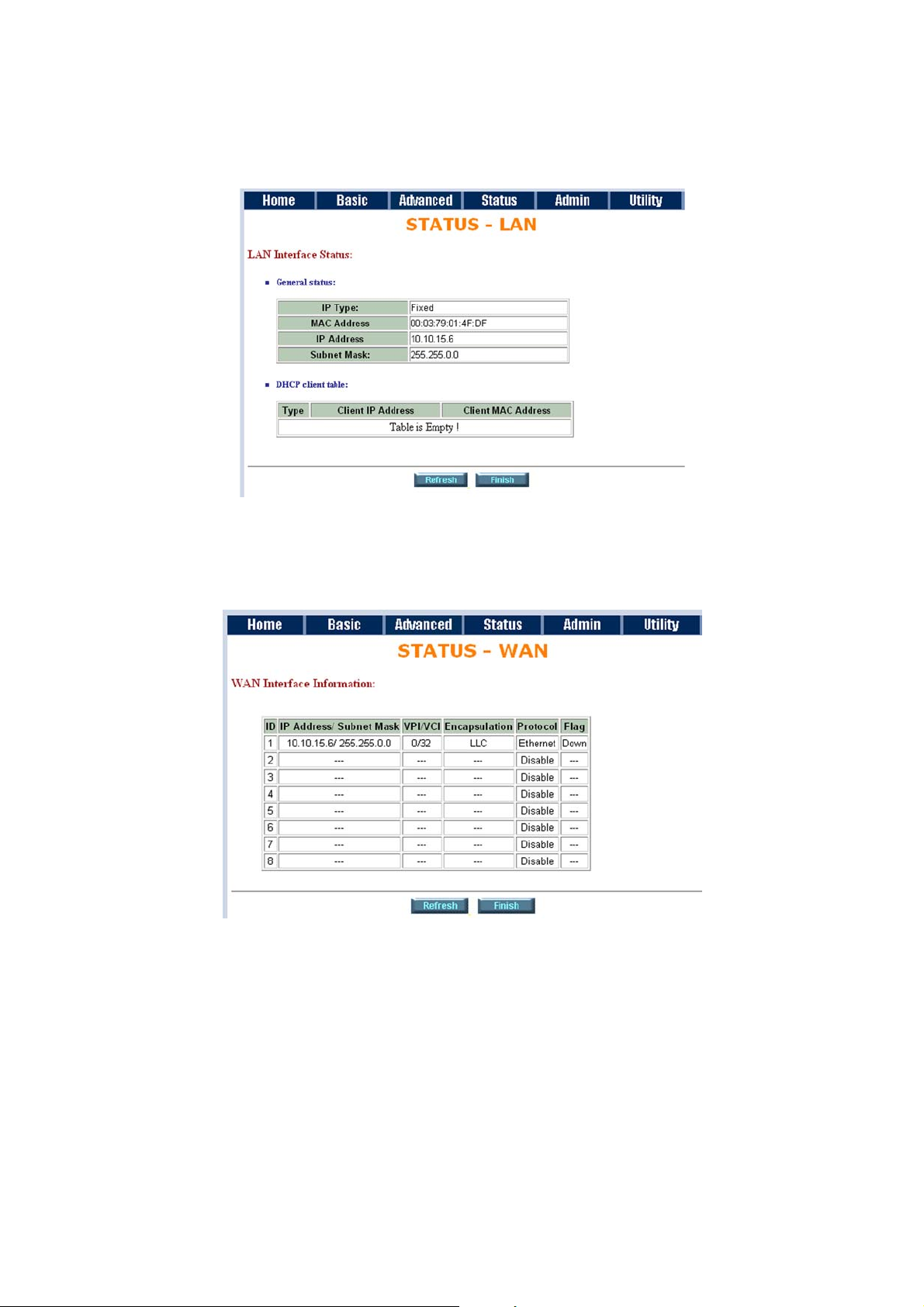
6.6.2 LAN
LAN status will prompt the MAC address, IP address, Subnet mask and DHCP client table.
6.6.3 WAN
WAN status will display the WAN interface information.
Page 57
ATL User Guide
AM2 G.SHDSL Modem
57
6
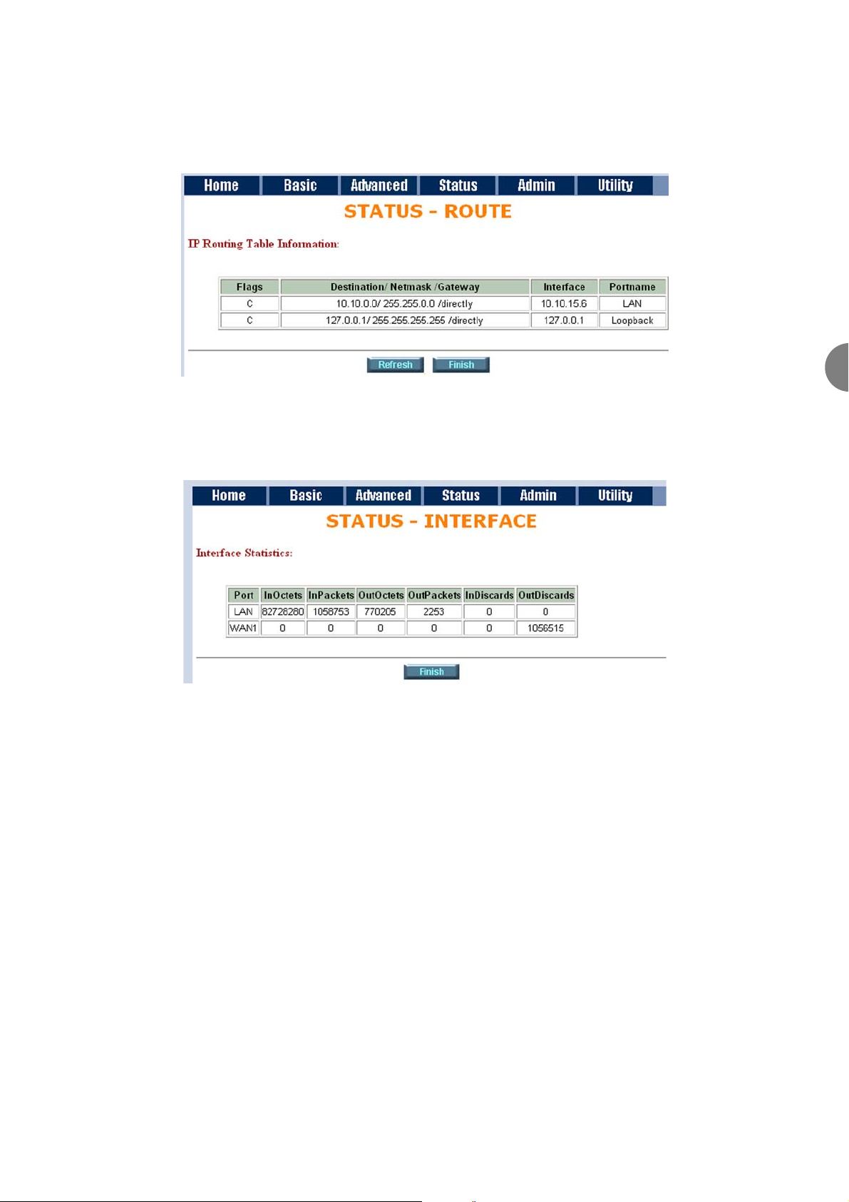
6.6.4 ROUTE
You can view the routing table in Status of Route.
6.6.5 INTERFACE
Interface status includes LAN and WAN statistics.
Firewall status displays DoS protection status and dropped packets statistics.
Page 58
ATL User Guide
AM2 G.SHDSL Modem
58
6.7 ADMINISTRATION
This session introduces security and simple network management protocol (SNMP) and time synch.
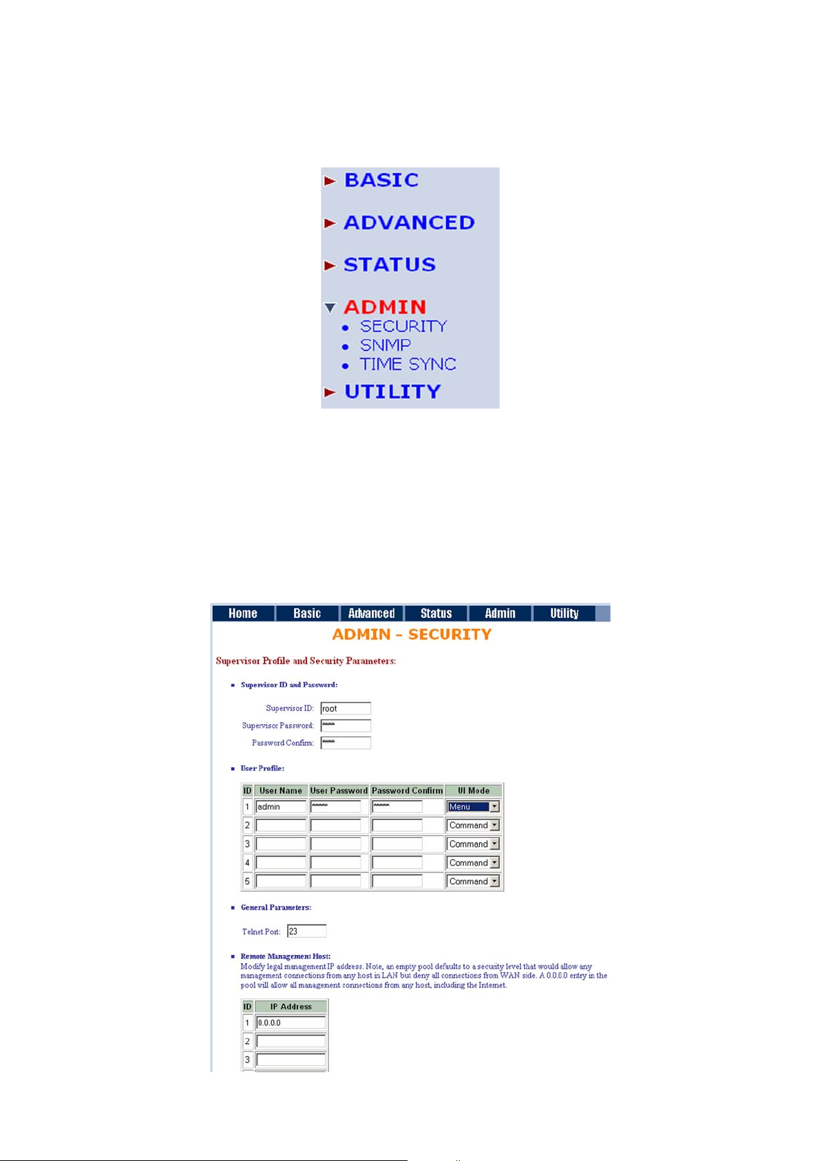
6.7.1 SECURITY
For system security, we suggest you change the default user name and password in the first setup otherwise
unauthorized persons can access the modem and change parameters.
There are three ways to configure the modem, Web browser, telnet and serial console.
Press Security to setup the parameters.
Page 59
ATL User Guide
AM2 G.SHDSL Modem
59
6
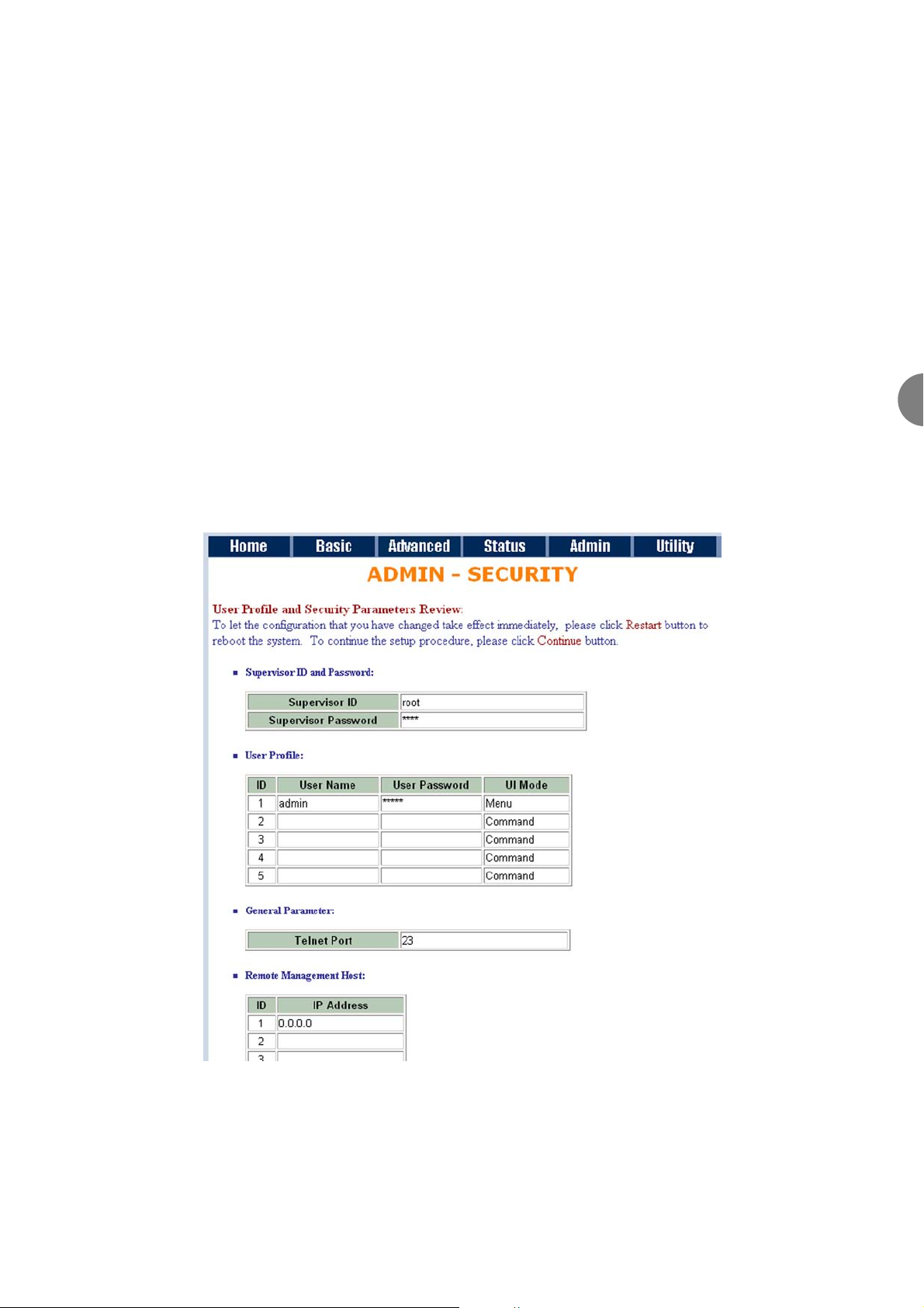
For greater security, change the Supervisor ID and password for the gateway. If you don't set them, any users
on your network will be able to access the gateway using the default IP and Password root.
You can authorize five legal users to access the modem via telnet or console. There are two UI modes, menu
driven mode and command mode to configure the modem.
Legal address pool will setup the legal IP addresses from which authorized persons can configure the
gateway. This is the best security setting for network administrators to setup legal address of configurations.
Configure 0.0.0.0 will allow all hosts on the Internet or LAN to access the modem.
Leaving the action trust host list blank will cause all PCs from WAN to be blocked from accessing the modem.
On the other hand, only PCs in the LAN can access the modem.
If you type the complete IP address in the file, only the host can access the modem.
Click Finish to complete the setting.
The browser will prompt for the configured parameters and check it before writing into EPROM.
Press Restart to restart the gateway with the new parameters and press Continue to setup other parameters.
Page 60
ATL User Guide
AM2 G.SHDSL Modem
60
6.7.2 SNMP
Simple Network Management Protocol (SNMP) provides for the exchange of messages between a network
management client and a network management agent for remote management of network nodes. These
messages contain requests to get and set variables that exist in network nodes in order to obtain statistics,
set configuration parameters, and monitor network events. SNMP communications can occur over the LAN
or WAN connection.
The modem can generate SNMP traps to indicate alarm conditions, and it relies on SNMP community strings
to implement SNMP security. This modem supports MIB I and MIB II.
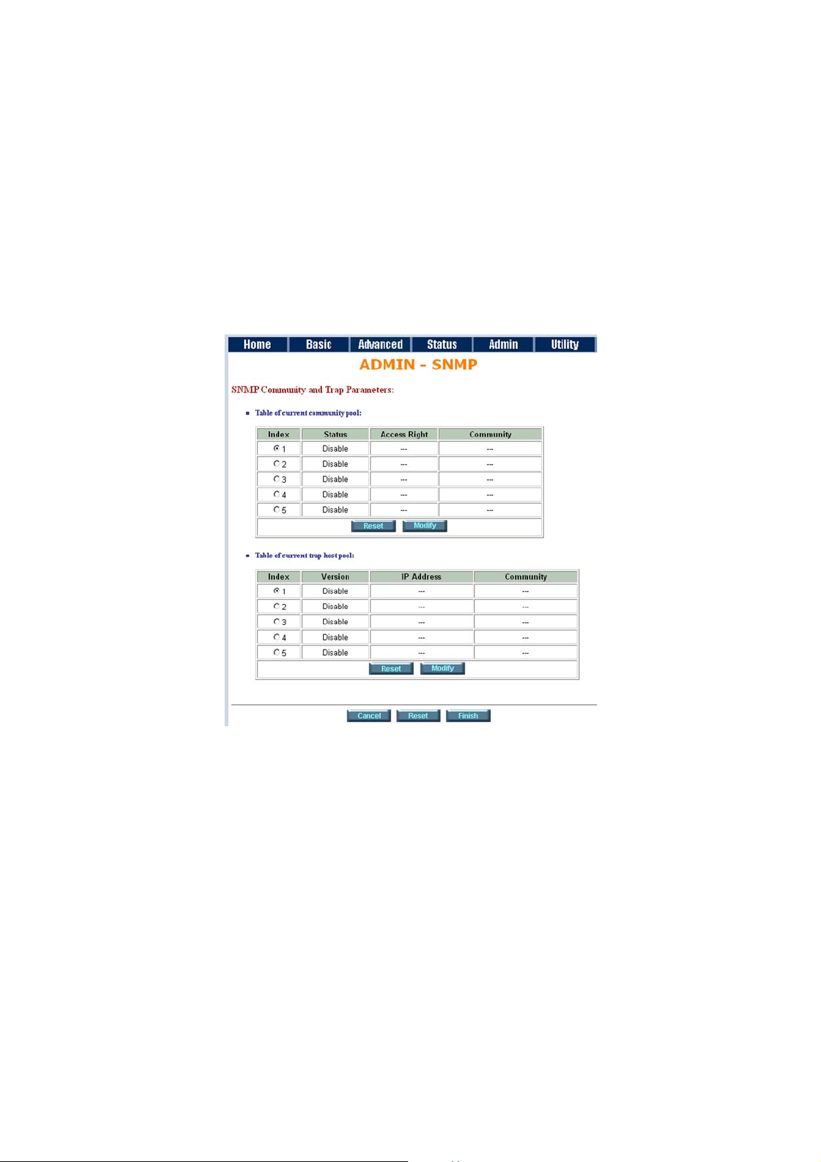
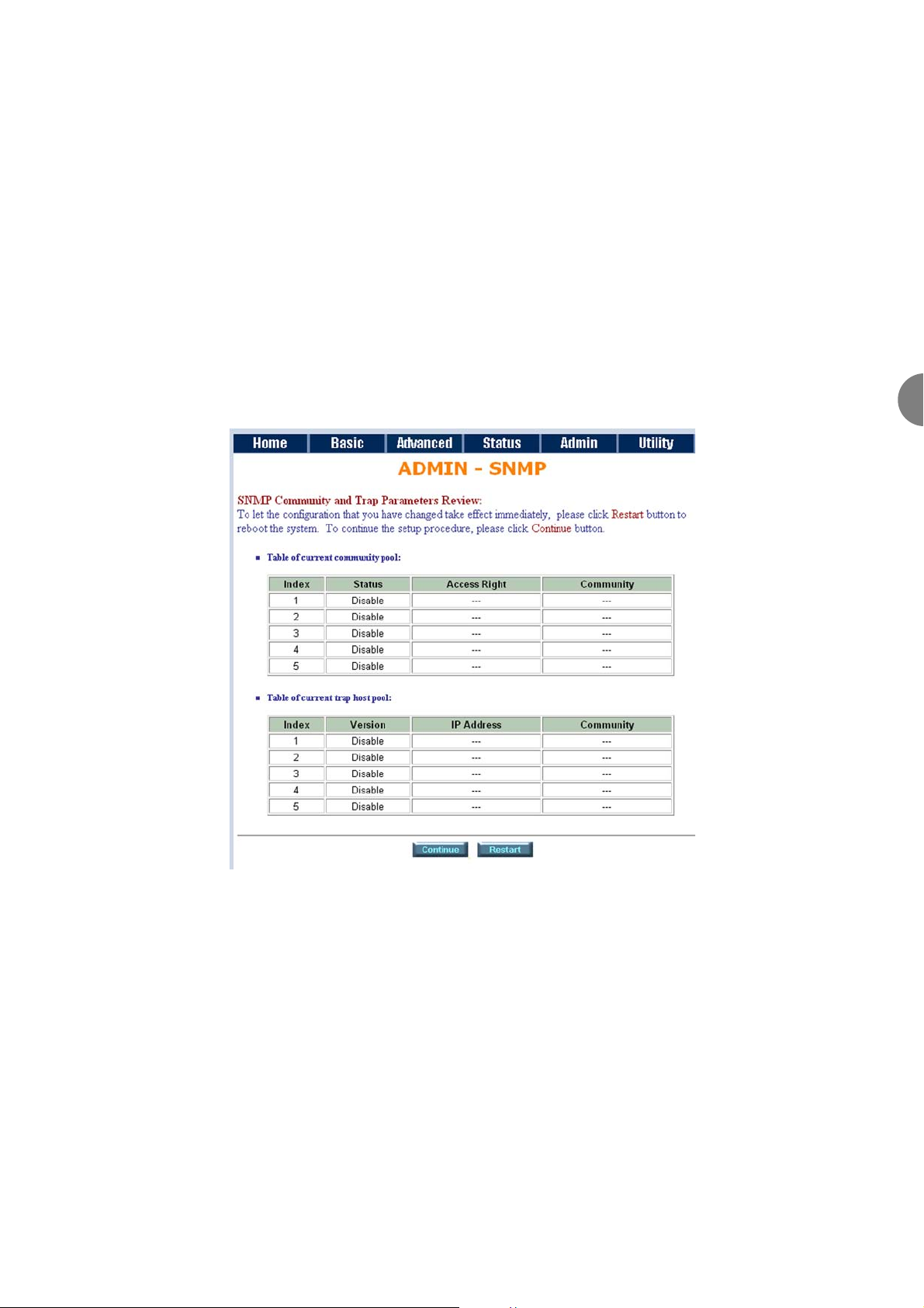
Click SNMP to configure the parameters.
In the current community pool table, you can setup the access authority.
In the current trap host pool table, you can setup the trap host.
Press Modify to modify the community pool.
SNMP status: Enable
Access Right: Deny to deny all access
Access Right: Read for access read only
Access Right: Write for access read and write.
Community: serves as password for access right.
After configuring the community pool, press OK.
Page 61
ATL User Guide
AM2 G.SHDSL Modem
61
6
SNMP trap is an information message sent from an SNMP agent to a manager. Click Modify to modify the
trap host pool.
Version: select version for trap host (SNMP v1 or SNMP v2).
IP: type the trap host IP
Community: type the community password. The community is setup in community pool.
Press OK to finish the setup.
The browser will prompt for the configured parameters and check it before writing into EPROM.
Press Restart to restart the gateway with the new parameters and press Continue to setup other parameters.
Page 62
ATL User Guide
AM2 G.SHDSL Modem
62
6.7.3 TIME SYNC
Time synchronization is an essential element for any business that relies on an IT system. The reason for this
is that these systems all have clocks that are the source of time for files or operations they handle. Without
time synchronization, time on these systems varies between each other or with the correct time and this can
cause-, firewall packet filtering schedule processes to fail, security to be compromised, or the virtual server to
works in the wrong schedule.
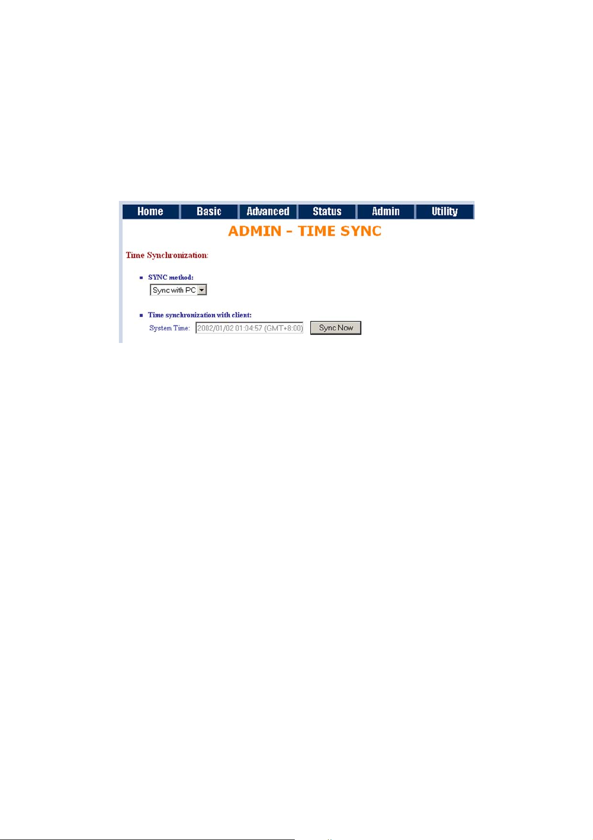
Click TIME SYNC.
There are two synchronization modes: Sample Network Time Protocol (SNTP) and synchronization with PC.
For synchronization with PC, select Sync with PC. The gateway will synchronize the time with the connecting
PC.
SNTP is the acronym for Simple Network Time Protocol, which is an adaptation of the Network Time Protocol
(NTP) used to synchronize computer clocks in the Internet. SNTP can be used when the ultimate performance
of the full NTP implementation.
For SNTP, select SNTP v4.0.
SNTP service: Enable
Time Server: All of the time server around the world can be used but suggest to use the timeserver nearby.
Time Zone: you have to choose the right time zone.
Press Finish to finish the setup. The browser will prompt the configured parameters and check it before writing
into EPROM.
Page 63
ATL User Guide
AM2 G.SHDSL Modem
63
6
6.8 UTILITY
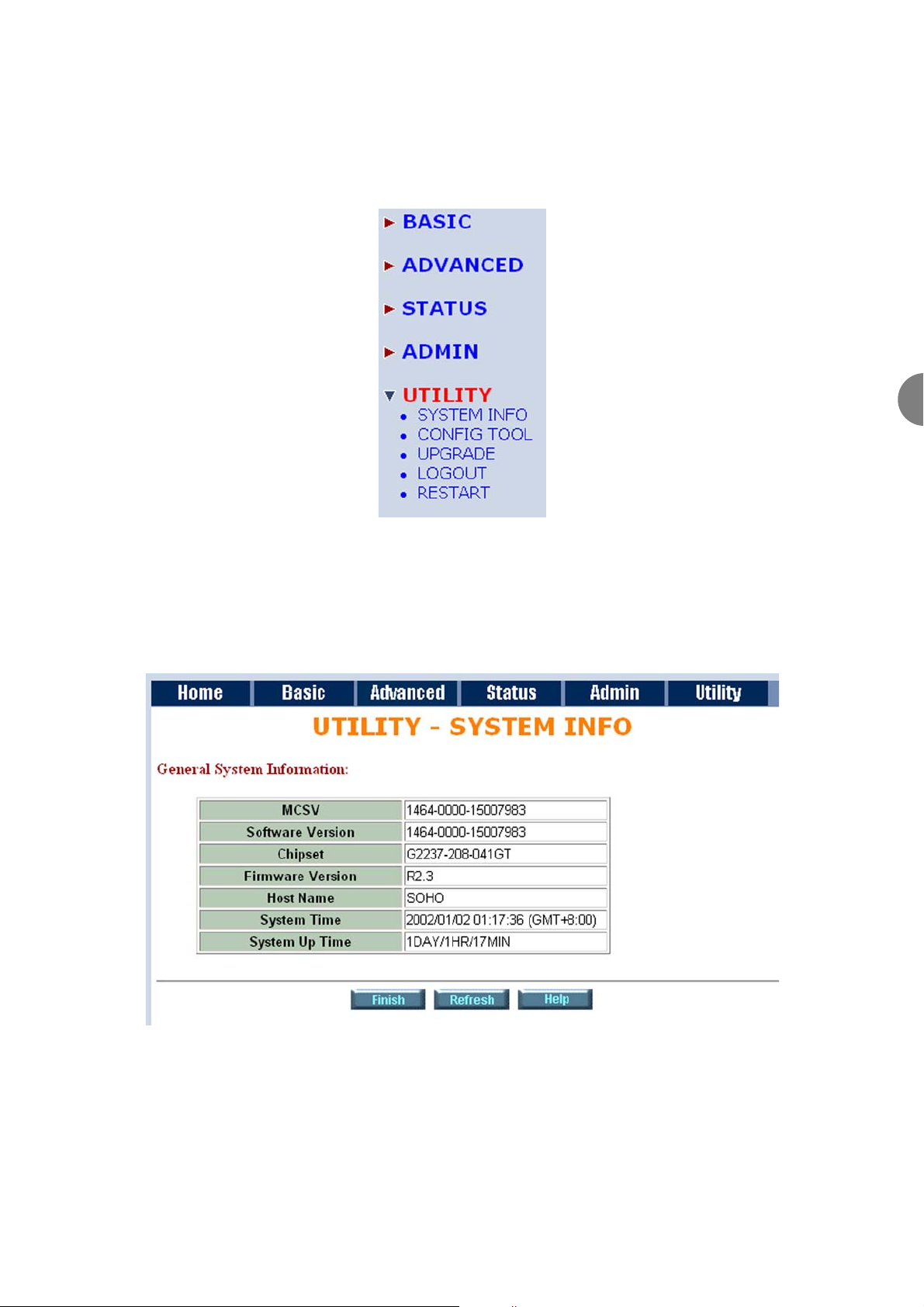
This section will describe the utility settings, including system information, loading the factory default
configuration, upgrading the firmware logout and restarting the gateway.
6.8.1 SYSTEM INFO
Click System Info to review the information.
The browser will prompt the system information.
Page 64
ATL User Guide
AM2 G.SHDSL Modem
64
6.8.2 CONFIG TOOL
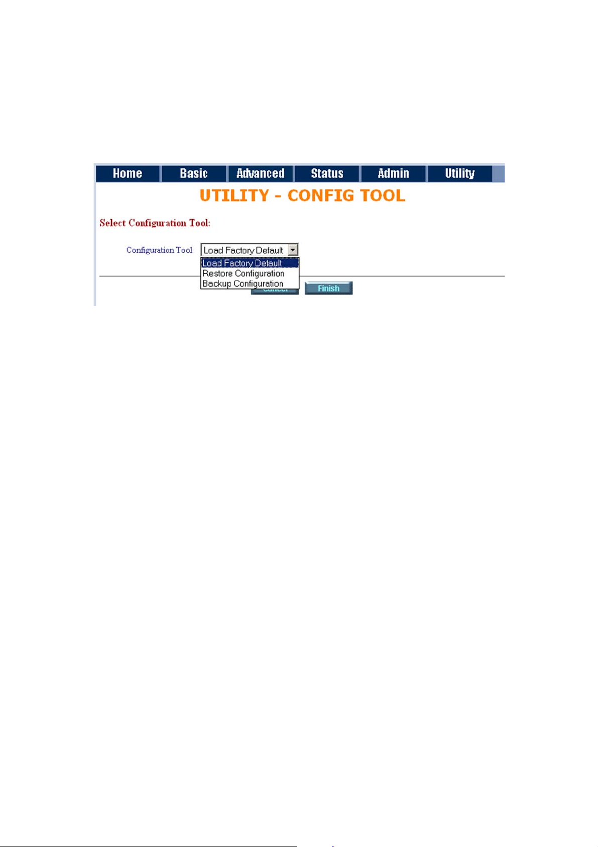
This configuration tool has three functions: load Factory Default, Restore Configuration and Backup
Configuration.
Press Config Tool.
Choose the function and then press finish.
Load Factory Default function: will load the factory default parameters to the gateway.
Note: All of the settings will be changed to factory default. You will lose all configured parameters.
Restore Configuration: Sometimes the configuration will be lost unintentionally. Restore configuration will
recover the backup configuration easily.
Click Finish after selecting Restore Configuration.
Browse the route of backup file then press finish. The modem will automatically restore the saved
configuration.
Backup Configuration: After configuration, we suggest using this function to backup your modem
parameters in the PC.
Select the Backup Configuration and then press Finish.
Browse to the backup file named backup. Press Finish. The modem will automatically backup the
configuration.
Page 65
ATL User Guide
AM2 G.SHDSL Modem
65
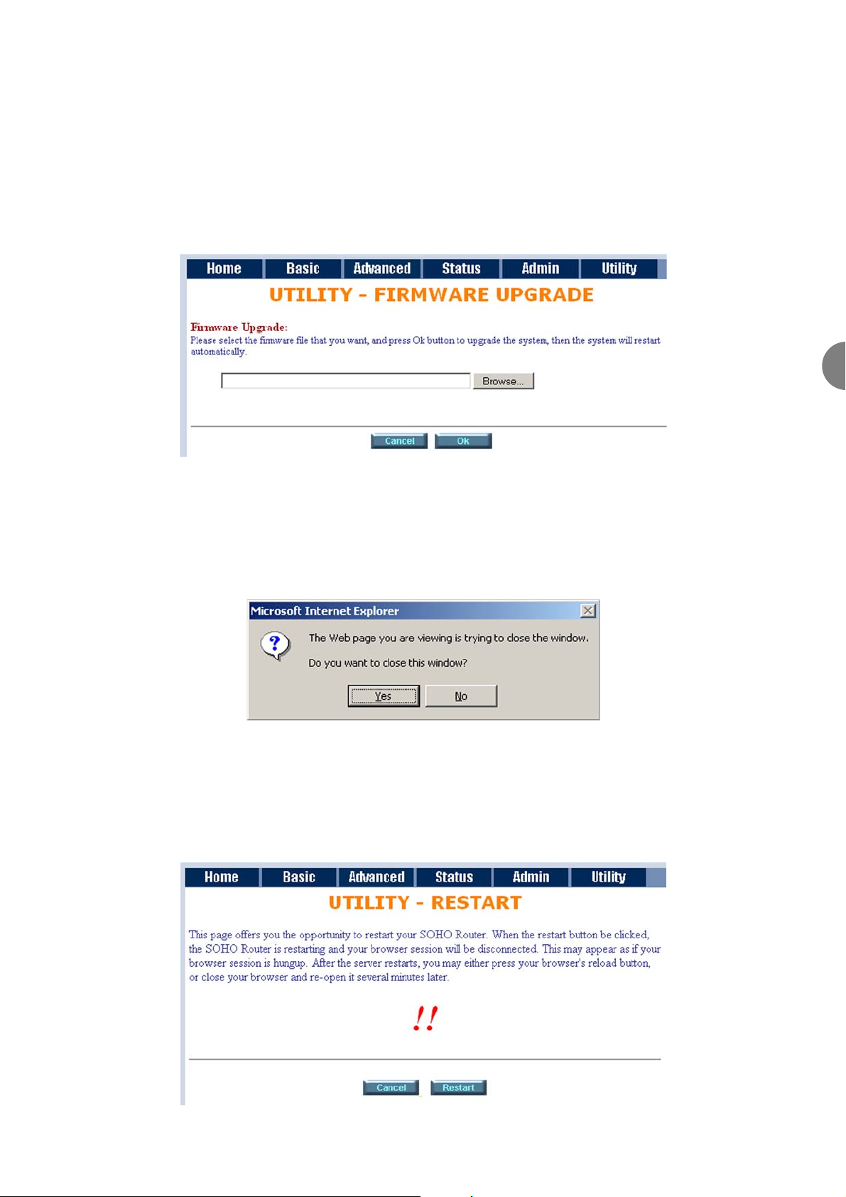
6.8.3 UPGRADE
You can upgrade the gateway using the upgrade function.
Press Upgrade.
Browse the file and press OK button to upgrade. The system will reboot automatically after finishing.
6.7.4 LOGOUT
To logout the modem, press logout.
6.7.5 RESTART
To restart the modem, click the Restart in UTILITY.
6
Page 66
ATL User Guide
AM2 G.SHDSL Modem
66
7 CONFIGURATION VIA THE CONSOLE PORT
The AM2 can be set-up and controlled via the Command Line Interface (CLI) or via the Menu Driven Interface.
Both interfaces can be accessed via a VT100 Terminal or PC connected to the console port, or via a PC
connected to the LAN port.
The Menu Driven Interface is a user friendly interface that does not require the user to remember the exact
CLI syntax code for each command. The CLI mode requires the user to type in the commands. The Menu
Driven interface is the default interface
The PC needs to be running the TeraTerm VT100 emulation program. This program can be down loaded from
the ATL website http://www.atltelecom.com/support/.
7.1 CONNECTION VIA THE CONSOLE PORT
Connect a VT100 terminal (or PC running TeraTerm VT100 emulation program) to the 9-way Console serial
port on the back of the unit. Configure the serial port settings of the VT100 terminal to 9,600 baud, 8 bits,
no parity, 1 stop bit and Xon/Xoff.
Press the Space Bar key until the logon prompt appears. Type in the default login user name admin. The
password prompt will then appear on the screen. Type in the default password admin.The Menu Drive
Interface menu will then appear on the screen
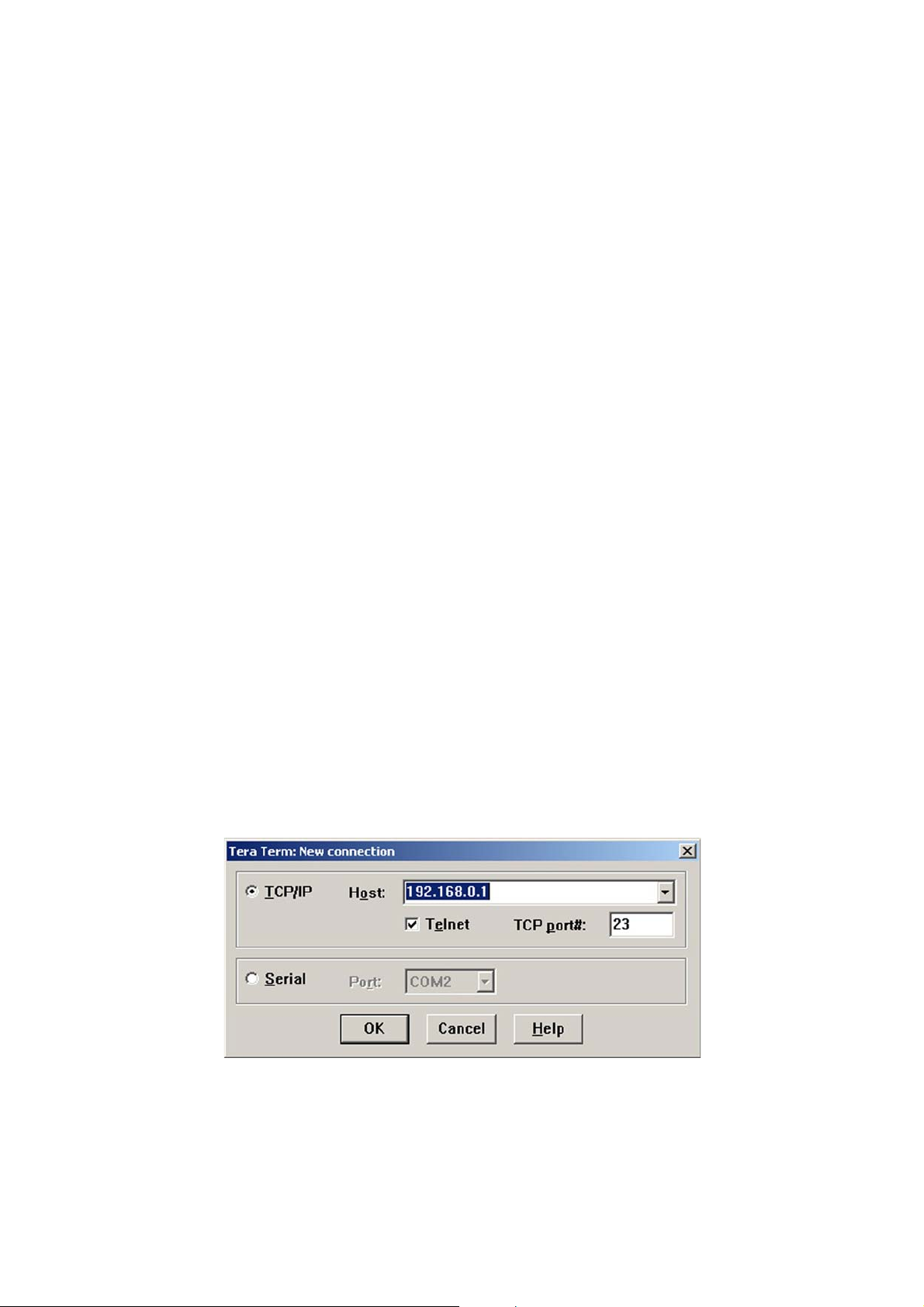
7.2 CONNECTION VIA TELNET
Connect an Ethernet cable from the Ethernet network to the LAN port on the rear of the unit. Start the
TeraTerm software package. From the Menu bar select File, select New Connection from the drop-down
menu.
Select the TCP/IP option and type in the default IP address for the AM2. The default IP address is
192.168.0.1
Click on the OK button to save the connection.
Press the Space Bar key until the logon prompt appears. Type in the default login user name admin. The
password prompt will then appear on the screen. Type in the default password admin.
The Menu Drive Interface menu will then appear on the screen.
Page 67
ATL User Guide
AM2 G.SHDSL Modem
67
7
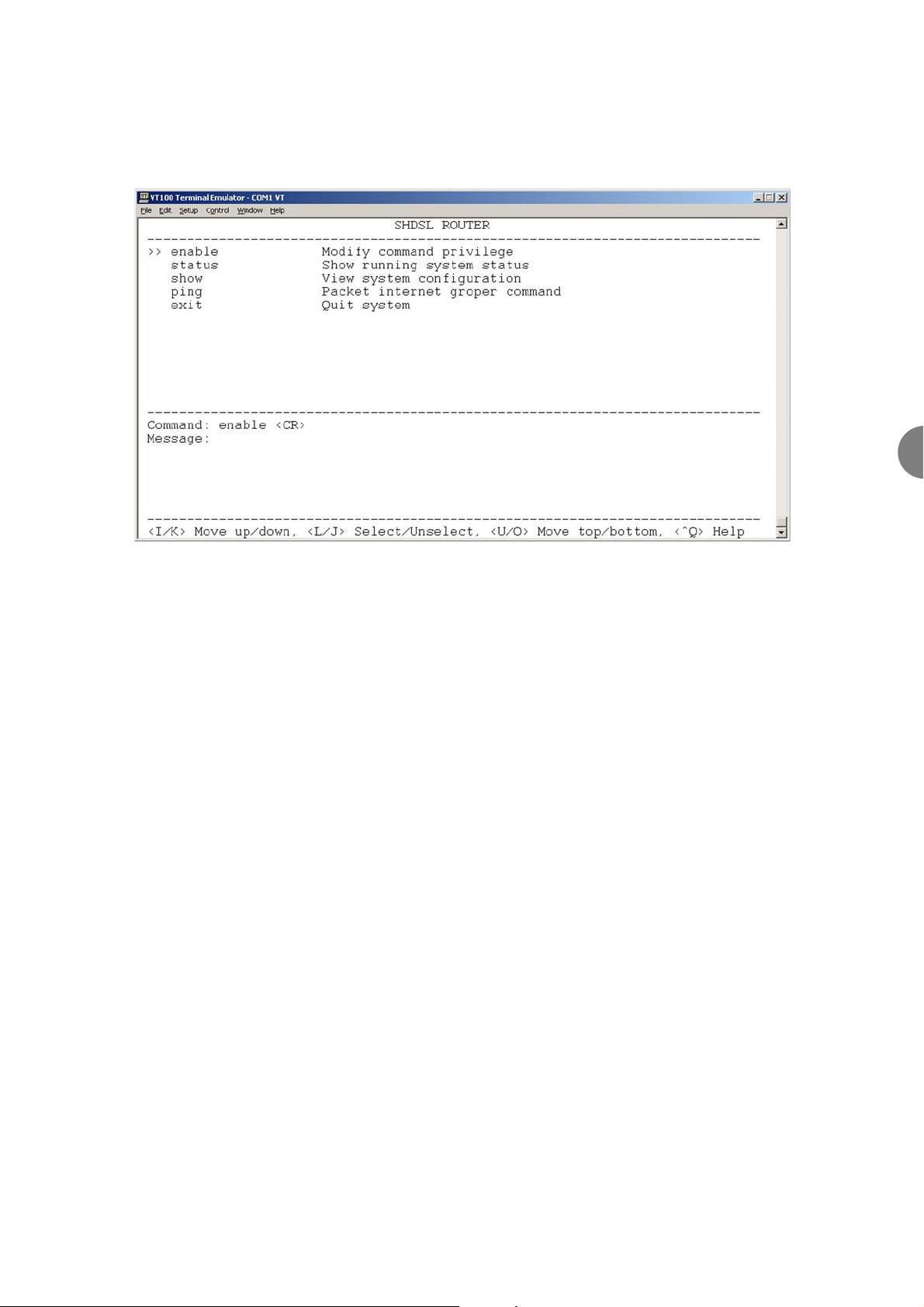
7.3 MENU DRIVEN INTERFACE
After logging into the AM2 the following menu will be displayed on the screen.
Specific keys are used to move around and access the various menu functions.The key commands are shown
below. They are also displayed at the bottom of the interface screen.
Command Key
Scroll up I or [Up arrow]
Scroll down K or [Down arrow]
Select a command L or [Enter]
Back to the previous menu J or [Left arrow]
To quit the action Ctl + C
Help Ctl + Q
Scroll between option [TAB]
Page 68
ATL User Guide
AM2 G.SHDSL Modem
68
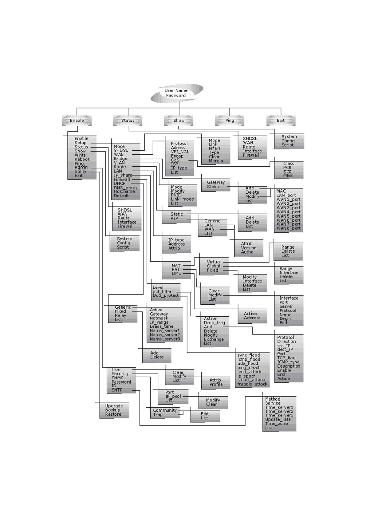
7.3.1 MENU STRUCTURE
The menu structure is shown below. All of the configuration sub-menus are accessed via the Enable menu.
Access to this menu is also password protected to eliminate any un-authorised changes.
Page 69

ATL User Guide
AM2 G.SHDSL Modem
69
7.3.2 ENABLE
To Configure the modem, move the cursor " >>" to the enable option and press the enter key. You will now
be prompted to type in the Supervisor Password. The default supervisor password is root. The password will
be prompted as " * " symbol for system security.
Command: enable <CR>
Message: Please input the following information.
Supervisor password: ****
The screen will now display the following sub-menu.
>> enable Modify command privilege
setup Configure system
status Show running system status
show View system configuration
write Update flash configuration
reboot Reset and boot system
ping Packet internet groper command
admin Setup management features
utility TFTP upgrade utility
exit Quit system
In the displayed sub menu, you can setup management features, upgrade software, backup the system
configuration and restore the system configuration.
IMPORTANT NOTE: - For any configuration changes, you have to write the new configuration to the FLASH,
save the configuration and reboot the AM2 to work with the new configuration.
Each of the sub-menu options are described below.
7
Page 70

ATL User Guide
AM2 G.SHDSL Modem
70
7.3.2.1 SETUP
All of the configuration parameters for the AM2 are located in this menu. From the enable menu, move
cursor " >> " to the setup command and press the enter key .
The screen will now display the following sub-menu.
>> mode Switch system operation mode
shdsl Configure SHDSL parameters
wan Configure WAN interface profile
bridge Configure transparent bridging
vlan Configure virtual LAN paramters
route Configure routing parameters
lan Configure LAN interface profile
ip_share Configure NAT/PAT parameters
firewall Configure Firewall parameters
dhcp Configure DHCP parameters
dns_proxy Configure DNS proxy parameters
hostname Configure local host name
default Restore factory default setting
enable
The enable option allows the user to modify the current user privilege
setup
The setup option allows the user to congure the modem
status
The status opyion displays the current status of the modem
show
The show option displays the current hardware and software conguration
s
write
The write option allows the user to write the new conguration to the FLASH
COMMAND
DESCRIPTION
reboot
ping
admin
utility
exit
The reboot option allows the user to reboot the modem using the last saved
conguration
The ping option allows the user to test the LAN connection by using the Packet
InterNet Groper (PING) command
The admin option allows the user to setup the user and supervisor security and
password
The utility option allows the user to update the software
The exit option allows the user to exit the modem command line interface
Page 71

ATL User Guide
AM2 G.SHDSL Modem
71
7.3.2.1.1 MODE
The modem can act as a router or as a bridge. The default setting is routing mode. You can change the system
operation mode by using mode command. Move the cursor " >> " to mode command and press the enter
key.
The following message is displayed.
Command: setup mode <Route|Bridge>
Message: Please input the following information.
System operation mode (TAB select) <Route>: Route
Use the TAB key to switch between the two options. Once the required option is displayed press the enter
key.
7.3.2.1.2 SHDSL
The SHDSL parameters can be setup by using the shdsl command. Move the cursor " >> " to shdsl command
and press the enter key.
The following sub-menu will be displayed
>> mode Configure SHDSL mode
Link Configure SHDSL link
n*64 Configure SHDSL data rate
type Configure SHDSL annex type
clear Clear current CRC error count
margin Configure SHDSL SNR margin
Mode
There are two types of SHDSL mode, STU-R and STU-C. STU-R denotes CO (Central Office) unit. STU-C
denotes CPE (Customer Premises Equipment) unit.
Link
The link type will always be 2-wire mode on AM2.
N*64
You can setup the data rate by a multiple of 64kbps where n is from 0 to 32. If you configure n i= 0, the
product will perform in adaptive mode.
Type
There are two types of SHDSL Annex type, Annex-A and Annex-B.
7
Page 72

ATL User Guide
AM2 G.SHDSL Modem
72
Clear
The Clear command will clear the current CRC error count to zero.
Margin
Generally, you will not need to change SNR margin, whose range is from 0 to 10. SNR margin is an index of
the line connection. You can see the actual SNR margin in STATUS SHDSL menu. The larger the SNR margin,
the better the line connection. If you set the SNR margin to 2, the SHDSL connection will drop and reconnect
when the SNR margin is lower than 2. Or, the device will reduce the line rate and then reconnect for better
line connection.
7.3.2.1.3 WAN
The modem supports 8 PVC (Private Virtual Circuit), and so you can set up to eight WAN circuits,from WAN1
to WAN8. Move the cursor " >> " to the wan command and press the enter key. To setup WAN1 type 1, to
setup WAN2 type in 2 etc..
Command: setup wan <1~8>
Message: Please input the following information.
Interface number <1~8>:
Enter the required wan number and press the enter key. The following sub-menu will now be displayed.
>> protocol Link type protocol
address IP address and subnet mask
vpi_vci Configure VPI/VCI value
encap Configure encapsulation type
qos Configure VC QoS
isp Configure account name, password and idle time
ip_type Configure IP type in PPPoA and PPPoE
list WAN interface configuration
Protocol
There are four types of protocols that can be selected , IPoA, EoA, PPPoA and PPPoE, which you can setup.
IP Address
Allows the user to set the IP Address. Note, for dynamic IP of PPPoA and PPPoE, you do not need to enter the
IP address and subnet mask.
Page 73

ATL User Guide
AM2 G.SHDSL Modem
73
VPI VCI
There is an unique VPI and VCI value for Internet connection supported by ISP. The range is from 0 to 255
and VCI from 0 to 65535..
ENCAP
There are two types of encapsulation, VC-Mux and LLC.
QoS
You can setup the PVC quality of service, VC QoS, using qos command. The product supports UBR, CBR, VBRrt and VBR-nrt. The peak cell rate can be configured from 64kbps to 2400kbps. Move the cursor to the qos
command and press the enter key. The following sub-menu will be displayed.
>> class Configure QoS class
pcr Configure peak cell rate (kbps)
scr Configure sustainable cell rate (kbps)
mbs Configure max. burst size (cell)
ISP
The ISP command is used to configure the account name, password and idle time.The Idle time can be set
from 0 to 300 minutes.
IP-Type
Allows the user to select either Dynamic IP or Static IP.
List
You can review the WAN interface configurations using the list command.
7
Page 74

ATL User Guide
AM2 G.SHDSL Modem
74
7.3.2.1.4 BRIDGE
If the AM2 has been configured as a bridge, you can use the bridge command to setup the bridge parameters.
Move the cursor " >> " to the bridge command and press the enter key. The following sub menu will be
displayed.
>> gateway Default gateway
static Static bridging table
You can setup the default gateway IP via gateway command.
You can set up to 20 sets of static bridge using the static command. From the bridge menu, move the cursor
" >> " to the static command and press the enter key .
The screen will now display the following sub-menu.
>> add Add static MAC entry
delete Delete static MAC entry
modify Modify static MAC entry
list Show static bridging table
From the static menu, move the cursor " >> " to the add command and press the enter key .The screen will
now display the following sub-menu.
>> mac Configure MAC address
lan_port Configure LAN interface bridging type
wan1_port Configure WAN1 interface bridging type
wan2_port Configure WAN2 interface bridging type
wan3_port Configure WAN3 interface bridging type
wan4_port Configure WAN4 interface bridging type
wan5_port Configure WAN5 interface bridging type
wan6_port Configure WAN6 interface bridging type
wan7_port Configure WAN7 interface bridging type
wan8_port Configure WAN8 interface bridging type
list Show static bridging table
Page 75

ATL User Guide
AM2 G.SHDSL Modem
75
7.3.2.1.5 VLAN
Virtual LAN (VLAN) is defined as a group of devices on one or more LANs that are configured so that they can
communicate as if they were attached to the same wire, when in fact they are located on a number of
different LAN segments. Because VLAN is based on logical instead of physical connections, it is extremely
flexible.
You can setup the Virtual LAN (VLAN) parameters using the vlan command. The AM2 supports the
implementation of VLAN-to-PVC only in bridge mode operation, i.e., the VLAN spreads over both the COE
and CPE sides, where there is no layer 3 routing involved. The unit supports up to 8 active VLANs with shared
VLAN learning (SVL) bridge out of 4096 possible VLANs specified in IEEE 802.1Q.
From the setup menu, move the cursor " >> " to the vlan command and press the enter key .The screen
will now display the following sub-menu.
>> mode Trigger virtual LAN function
modify Modify virtual LAN rule
pvid Modify port default ID
link_mode Modify port link type
list Show VLAN configuration
Mode
To activate the VLAN function, move the cursor " >> " to mode command and press the enter key. The
products support two types of VLAN, 802.1q and Port-Based. IEEE 802.1q defines the operation of VLAN
bridges that permits the definition, operation, and administration of VLAN topologies within a bridged LAN
infrastructure. Port-Based VLANs are VLANs where the packet forwarding decision is based on the destination
MAC address and its associated port. On selecting the mode command the following message is displayed.
Use the TAB key to switch betwen the two options, Port or 802.1q.
Command: setup vlan active <Disable|8021Q|Port>
Message: Please input the following information.
Tigger VLAN function (Tab select) <Disable>:
Modify
To modify the VLAN rule, move the cursor " >> " to the modify command and press the enter key.
Command: setup vlan modify <1~8> <1~4094> <string>
Message: Please input the following information.
Rule entry index <1~8>:
VLAN ID (Enter for default) <1>:
VLAN port status (Enter for default):
7
Page 76

ATL User Guide
AM2 G.SHDSL Modem
76
The VLAN ID is a unique number ranging from 1~4095.
The VLAN port status is a 12-digit binary number whose bit-1 location indicates the VLAN port membership
in which 4MSBs and 8LSBs represent the LAN port and WAN port, respectively. For example, setting the Port
Status to 10001, means that the VID 20 member port includes LAN and WAN. The member ports are tagged
members. Use the PVID command to change the member port to untagged members
PVID
To assign PVID (Port VID), move the cursor ">>" to PVID command and press the enter key. The port index
1 represents LAN1 and port index 5 to 12 represents WAN1 to WAN8. On selecting the PVID command the
following message is displayed
Command: setup vlan pvid <1~12> <1~4094>
Message: Please input the following information.
Port index <1~12>:
VID Value (Enter for default) <10>:
Link_Mode
To modify the link type of the port, move the cursor to link_mode command and press the enter key. There
are two types of link: access and trunk. A Trunk link will send the tagged packet from the port and an Access
link will send an un-tagged packet from the port. Port index 1 represents LAN1. According to the operation
mode of the device, the link type of the WAN port is automatically configured. If the product operates in
bridge mode, the WAN link type will be Trunk, and in routing mode it will be Access. On selecting the
Link_mode command the following message is displayed
Command: setup vlan link_mode <1~12> <Access|Trunk>
Message: Please input the following information.
Port index <1~12>:
Port link type (Tab select) <Trunk>:
List
To view the VLAN table, move the cursor to the list command and press the enter key.
Page 77

ATL User Guide
AM2 G.SHDSL Modem
77
7.3.2.1.6 ROUTE
You can setup the routing parameters using the route command. If the modem is configured as a router,.
move the cursor " >> " to the route command and press the enter key. The following sub menu will be
displayed.
>> static Configure static routing table
rip Configure RIP tool
If the modem is connected to more than one network, it may be necessary to set up a static route between
them. A static route is a pre-determined pathway that the network information must travel to reach a specific
host or network.
With Dynamic Routing, you can enable the router function in the modem to automatically adjust to physical
changes in the network's layout. Using the RIP protocol, it determines the network packets' route based on
the fewest number of hops between the source and the destination. The RIP protocol regularly broadcasts
routing information to other routers on the network.
Static
You can set up to 20 sets of static route in static command. After entering the static menu, the screen will
display the follwing sub menu
>> add Add static route entry
delete Delete static route entry
list Show static routing table
You can add up to 20 sets of static route by using the add command. Type in the IP information of the static
route including IP address, subnet mask and gateway.
You can delete the static route information via the delete command.
You can review the static routes by using the list command.
Rip
To configure Routing Information Protocol (RIP), you can use the rip command to setup the parameters. Move
the cursor ">>" to rip command and press the enter key. After entering the rip menu, the screen will display
the following sub menu
>> generic Configure operation and auto summary mode
lan Configure LAN interface RIP parameters
wan Configure WAN interface RIP parameters
list Show RIP configuration
7
Page 78

ATL User Guide
AM2 G.SHDSL Modem
78
The Generic command is used to setup the RIP mode and auto summary mode.
If there are any routers in your LAN, you can configure the LAN interface RIP parameters via the lan command.
The product supports 8 PVCs and you can configure the RIP parameters of each WAN via the wan command.
Move the cursor ">>" to wan command and press the enter key. The screen will now display the following
sub-menu.
Command: setup route rip wan <1~8> <more...>
Message: Please input the following information.
Active interface number <1~8>:
The screen will prompt as follow:
>> attrib Operation, authentication and Poison reverse mode
version RIP protocol version
authe Authentication code
Attrib command can configure RIP mode, authentication type and Poison reverse mode.
Version command can configure RIP protocol version.
Authe command can configure authentication code.
You can review the list of RIP parameters via the list command.
7.3.2.1.7 LAN
The LAN command allows the user to configure the LAN IP address, subnet mask and NAT network type. To
enter the LAN menu, move the cursor to the LAN command and press the enter key. The screen will now
display the following sub-menu.
>> address LAN IP address and subnet mask
attrib NAT network type
7.3.2.1.8 IP SHARE
You can configure Network Address Translation (NAT), Port Address Translation (PAT) and Demilitarized Zone
parameters in the ip_share menu. Move the cursor ">>" to the ip_share command and then press the enter
key. The screen will now display the following sub-menu.
>> nat Configure network address translation
pat Configure port address translation
dmz Configure DMZ host function
Page 79

ATL User Guide
AM2 G.SHDSL Modem
79
Nat
You can configure NAT parameters in the nat menu.
>> virtual Virtual IP address pool
global Global IP address pool
fixed Fixed IP address mapping
Virtual
The virtual menu contains a range of virtual IP addresses, delete virtual IP addresses and show virtual IP
addresses.
>> range Edit virtual IP address pool
delete Delete virtual IP address pool
list Show virtual IP address pool
Range
You can create five virtual IP address pool ranges by using the range command.
Command: setup ip_share nat virtual range <1~5> <ip> <1~253>
Message: Please input the following information.
NAT local address range entry number <1~5>: 1
Base address: 192.168.0.2
Number of address: 49
Delete
You can delete virtual IP address ranges from 1 to 5- by using the delete command.
List
You can view the virtual IP address range by using the list command.
7
Page 80

ATL User Guide
AM2 G.SHDSL Modem
80
Global
To set up the global IP address pool, move the cursor ">>" to the global command and press the enter key.
>> range Edit global IP address pool
interface Bind address pool to specific interface
delete Delete global IP address pool
list Show global IP address pool
Range
You can create five global IP address pool ranges via the range command.
Command: setup ip_share nat global range <1~5> <ip> <1~253>
Message: Please input the following information.
NAT global IP address range entry number <1~5>: 1
Base address: 122.22.22.2
Number of address: 3
Interface
After configuration of the global IP address range, You can bind an address pool to a specific interface via the
Interface command.
Command: setup ip_share nat global interface <1~5> <1~8>
Message: Please input the following information.
NAT global ddress range entry number <1~5>: 1
Active interface number <1~8>: 1
Delete
You can delete global IP address ranges from 1 to 5 by using the delete command.
List
You can view the global IP address range via the list command.
Page 81

ATL User Guide
AM2 G.SHDSL Modem
81
Fixed
To modify a fixed IP address mapping, move the cursor ">>" to the fixed command and press the enter key.
>> modify Modify fixed NAT mapping
interface Bind address pair to specific interface
delete Delete fixed NAT mapping
list Show fixed IP address mapping
Modify
You can create up to 10 fixed NAT mapping entry via the modify command.
Command: setup ip_share nat fixed modify <1~1o> <ip> <ip>
Message: Please input the following information.
Fixed NAT mapping entry number <1~10>: 1
Local address: 192.168.0.250
Global address: 122.22.22.2
Interface
After configuration of the fixed IP address entry, you can bind the entry to a specific interface via the
interface command.
Command: setup ip_share nat fixed interface <1~5> <1~8>
Message: Please input the following information.
Fixed NAT mapping entry number <1~5>: 1
Active interface number (Enter for default) <1~8>: 1
Delete
You can delete fixed NAT mapping entrys- from 1 to 5- by using the delete command.
List
You can view the fixed NAT mapping entries via the list command.
7
Page 82

ATL User Guide
AM2 G.SHDSL Modem
82
PAT
To configure Port Address Translation, move the cursor ">>" to the pat and press the enter key.
>> clear Clear virtual server mapping
modify Modify virtual server mapping
list Show virtual server mapping pool
Clear
You can delete a virtual server mapping entry- from 1 to 10- by using the clear command.
Modify
You can create up to 10 virtual server mapping entries via the modify command.
Command: setup ip_share pat modify <1~10>
Message: Please input the following information.
Virtual server entry number <1~10>: 1
After entering the information, the screen will display the following sub-menu.
>> interface Active interface
port TCP/UDP port number
server Host IP address and port number
protocol Transport protocol
name Service name
begin The schedule of beginning time
end The schedule of ending time
Set the active interface number via the interface command.
You can configure the global port number by using the port command.
The local server IP address and port number are configured via the server command.
The authorized access protocol is setup via the protocol command.
The name command can be used to configure the service name of the host server.
The begin and end commands are used to setup the local server schedule to access.
You can view the fixed NAT mapping entry via the list command.
Page 83

ATL User Guide
AM2 G.SHDSL Modem
83
DMZ
To setup the demilitarized zone, move the cursor ">>" to the dmz and press the enter key. The following
sub-menu will be displayed.
>> active Tigger DMZ host function
address Configure virtual IP address and interface
You can enable the demilitarized zone via the active command.
After enabling the DMZ, shift the cursor to the address command and press the enter key.
Command: setup ip_share dmz address <ip> <1~10>
Message: Please input the following information.
Virtual IP address: 192.168.0.251
Active interface number (Enter for default) <1>: 1
7.3.2.1.9 FIREWALL
The product supports advanced firewall. To setup the advanced firewall, you can use the firewall command.
>> Level Configure firewall security level
pkt_filter Configure packet filter
dos_protection Configure DoS protection
Level
There are three levels of firewall which you can setup in this product.
Level one, basic, only enables the NAT firewall and the remote management security. The NAT firewall will
take effect if the NAT function is enabled. The remote management security defaults to block any WAN side
connection to the device. Non-empty legal IP pool in ADMIN will block all remote management connection
except those IPs specified in the pool.
Level two, automatic, enables basic firewall security, all DoS protection, and the SPI filter function.
Level three, advanced, is an advanced level of firewall where the user can determine the security level for
special purpose, environment, and applications by configuring the DoS protection and defining an extra
packet filter with higher priority than the default SPI filter. Note that, an improper filter policy may degrade
the capability of the firewall and/or even block the normal network traffic.
The firewall security level can be configured via the The level command.
7
Page 84

ATL User Guide
AM2 G.SHDSL Modem
84
Packet Filtering
The packet filtering function can be configured by the pkt_filter command. Move the cursor to pkt_filter
command and press the enter key. The following sub-menu will be displayed
>> active Tigger packet filtering function
drop_flag Drop fragment packets
add Add packet filtering rule
delete Delete packet filtering rule
modify Modify packet filtering rule
exchange Exchange the filtering rule
list Show packet filtering table
To enable the packet filtering function use the active command.
To add the packet filtering rule use the add command. The following sub-menu will be displayed.
>> protocol Configure protocol type
direction Configure direction mode
src_ip Configure source IP parameter
dest_ip Configure destination IP parameter
port Configure port parameter (TCP and UDP only)
tcp_flag Configure TCP flag (TCP only)
icmp_type Configure ICMP flag (ICMP only)
description Packet filtering rule description
enable Enable the packet filtering rule
begin The schedule of beginning time
end The schedule of ending time
action Configure action mode
DoS Protection
The DoS protection parameters can be configured in the dos_protection menu. Move the cursor to
dos_protection command and press the enter key.
>> syn_flood Enable protection SYN flood attack
icmp_flood Enable protection ICMP flood attack
udp_flood Enable protection UDP flood attack
ping_death Enable protection ping of death attack
land_attack Enable protection land attack
ip_spoff Enable protection IP spoofing attack
smurf_attack Enable protection smurf attack
fraggle_attack Enable protection fraggle attack
Page 85

ATL User Guide
AM2 G.SHDSL Modem
85
7.3.2.110 DHCP
Dynamic Host Configuration Protocol (DHCP) is a communication protocol that lets network administrators
manage the network centrally and automate the assignment of Internet Protocol (IP) addresses in an
organization's network.When an organization sets up its computer users, a unique IP address must be
assigned to each machine.
Without DHCP, the IP address must be entered manually on each computer. If a computer is moved to another
location in another part of the network, a new IP address must be entered. DHCP allows a network
administrator to supervise and distribute IP addresses from a central point and automatically sends a new IP
address when a computer is plugged into a different place in the network.
To configure the DHCP server, move the cursor to dhcp command and press the enter key. The following
sub-menu will be displayed
>> generic Configure generic DHCP parameters
fixed Configure fixed host IP address list
list Show DHCP configuration
The generic DHCP parameters can be configured via generic command.
>> active Tigger DHCP function
gateway Default gateway for DHCP client
netmask Subnet mask for DHCP client
ip_range Dynamic assigned IP address range
lease_time Configure max lease time
name_server1 Domain name server1
name_server2 Domain name server2
name_server3 Domain name server3
The activate the DHCP function use the active command.
Set the default gateway vie the gateway command.
The subnet mask for the DHCP client is configured by using the netmask command.
Ip_range command is used to configure the dynamic assigned IP address range.
The dynamic IP maximum lease time is configured by via the lease_time command.
You can set upto 3 domain named servers via the name_server commands.
7
Page 86

ATL User Guide
AM2 G.SHDSL Modem
86
Fixed Host IP Address list are setup via the fixed command.
>> add Add a fixed host entry
delete Delete a fixed host entry
You can view the DHCP configuration via list command
7.3.2.1.11 DNS PROXY
You can set upto three DNS servers The number 2 and 3 DNS servers are optional. Move the cursor " >> "
to the dns_proxy command and press the enter key. The following sub-menu will be displayed.
Command: setup dns_proxy <IP> [IP] [IP]
Message: Please input the following information.
DNS server 1 (ENTER for default) <168.95.1.1>: 10.0.10.1
DNS server 2: 10.10.10.1
DNS server 3:
7.3.2.1.12 HOSTNAME
You enter the local host name via the hostname command. Move cursor " >> " to hostname command and
press the enter key.
Command: setup hostname <name>
Message: Please input the following information.
Local hostname (ENTER for default) <SOHO>: test
7.3.2.1.13 DEFAULT
If you want to restore the factory default settings, move the cursor " >> " to the default command and then
press the enter key.
Command: setup default <name>
Message: Please input the following information.
Are you sure? (Y/N):
Press Y to restore the factory default settings.
7.3.2.2 STATUS
The Status menu allows you to view the current status of the DSL line, firewall and the WAN and LAN
interfaces. From the enable menu, move the cursor " >> " to the status command and press the enter key
Page 87

ATL User Guide
AM2 G.SHDSL Modem
87
The screen will now display the following sub-menu.
>> shdsl Show SHDSL status
wan Show WAN interface status
route Show routing table
interface Show interface statistics status
firewall Show firewall status
Each of the sub-menu options are described below.
7.3.2.3 SHOW
The Show menu allows you to view the system and configuration information. From the enable menu, move
cursor " >> " to the show command and press the enter key .
The screen will now display the following sub-menu.
>> system Show general information
config Show all configurations
script Show all configuration in command script
Each of the sub-menu options are described below.
system
The general information regarding the modem is displayed
config
Displays all of the system configuration information
script
Displays the configuration information in CLI script format
COMMAND
DESCRIPTION
shdsl
The shdsl status option displays the status of the line rate, SNR margin, TX
power, attenuation and the CRC error of the unit. It also displays the SNR
margin, attenuation and CRC error for the remote unit (when two
modems
are configured back to back)
wan
The wan status option displays the status of the 8 PVC's
route
The route status option displays the routing table
interface
The interface status option displays the status of the WAN and LAN interfaces
firewall
The firewall status option displays the status and history of the firewall
COMMAND
DESCRIPTION
7
Page 88

ATL User Guide
AM2 G.SHDSL Modem
88
7.3.2.4 WRITE
Any changes to the configuration must be written to the FLASH and the unit rebooted. From the enable
menu, move cursor " >> " to the write command and press the enter key .
The screen will now display the following command
Command: write <CR>
Message: Please input the following information.
Are you sure? (y/n): y
Press Y to write the configuration to flash.
7.3.2.5 REBOOT
Following a write command the system must be rebooted for the new configuration to be used. From the
enable menu, move cursor " >> " to the reboot command and press the enter key.
The following message is displayed.
Command: reboot <CR>
Message: Please input the following information.
Do you want to reboot? (y/n): y
Press Y to reboot the AM2.
7.3.2.6 PING
The ping command allows the user to test the LAN connections. From the enable menu, move cursor " >>
" to the ping command and press the enter key.
The following message is displayed.
Command: ping <ip> [1~65534|-t] [1~1999]
Message: Please input the following information.
IP address <IP> : 10.0.0.1
Page 89

ATL User Guide
AM2 G.SHDSL Modem
89
Type in the IP address of the LAN connection you wish to test and press the enter key. The following message
will be displayed.
Number of ping request packets to send (TAB select):
There are three options. You can scroll through the options by pressing the TAB key,
Default - sends 4 request packets
1~65534 - Allows the user to set the number of packets. If this option is selected the display will prompt you
to enter the number of packets from 1 to 65534.
-t - Sends an unlimited number of packets. The test is terminated by pressing CTL+C
Once you have selected the required number of packets, press the enter key. The following message will be
displayed
Data size [1~1999]:
This allows the user to enter the size of the data packet (bytes). Once you have entered the data size, press
the enter key. The AM2 will now perform the required ping test and display the result
7.3.2.7 ADMIN
You can modify the user profile, telnet access, SNMP (Simple Network Management Protocol), supervisor
information and SNTP (Simple Network Time Protocol) via the admin command. To configure the parameters,
move the cursor " >> " to the admin command and press the enter key. The following sub menu will be
displayed
>> user Manage user profile
security Setup system security
snmp Configure SNMP parameter
passwd Change supervisor password
id Change supervisor ID
sntp Configure time synchronization
User
You can use the user command to clear, modify and list the user profile. You can set up to five users to access
the modem via the console port or telnet in user profile table, however users who have the supervisor
password can change the configuration of the modem. Move the cursor " >> " to the user command and
press the enter key. The following sub-menu will be displayed.
>> clear Clear user profile
modify Modify the user profile
list List the user profile
7
Page 90

ATL User Guide
AM2 G.SHDSL Modem
90
You can delete the user by number using the clear command. If you are not sure of the number of users, you
can use the list command to check it. Modify command is to modifies an old user information or adds a new
user to the user profile.
To modify or add a new user, move the cursor to the modify command and press the enter key.
Command: admin user modify <1~5> <more...>
Message: Please input the following information.
Legal access user profile number <1~5> :
The screen will prompt as follows.
>> Attrib UI mode
Profile User name and password
There are two UI modes, command and menu mode, to setup the product. We will not discuss the command
mode in this manual.
Security
The security command can be configured for sixteen legal IP addresses for telnet access and telnet port
number. Move the cursor " >> " to the security command and press the enter key. The default legal address
is 0.0.0.0. It means that there is no restriction on IP addresses to access the modem via the telnet.
>> port Configure telent TCP port
ip_pool Legal address IP address pool
list Show security profile
SNMP
Simple Network Management Protocol (SNMP) is the protocol not only governing network management, but
also monitoring network devices and their functions. The AM2 can generate SNMP traps to indicate alarm
conditions, and it relies on SNMP community strings to implement SNMP security. This unit also supports MIB
I & II. Move the cursor " >> " to the snmp command and press the enter key. The following sub-menu will
be displayed.
>> community Configure community parameter
trap Configure trap host parameter
Page 91

ATL User Guide
AM2 G.SHDSL Modem
91
Up to five SNMP community entries can be configured in this system. Move the cursor to the community
command and press the enter key.
Command: admin snmp community <1~5> <more...>
Message: Please input the following information.
Community entry number <1~5> : 2
The screen will now display the following.
>> edit Edit community entry
list Show community configuration
Up to five SNMP trap entries can be configured in this system. Move the cursor to the trap command and
press the enter key.
Command: admin snmp trap <1~5> <more...>
Message: Please input the following information.
Trap host entry number <1~5> : 2
The screen will now display the following
>> edit Edit trap host parameter
list Show trap configuration
Supervisor Password and ID
The supervisor password and ID are the last line of security defense and the most important. Users who access
the AM2 via the web browser have to use the ID and password to configure it. Users who access the AM2
via telnet or console mode have to use the password to configure it. We suggest you change the ID and
password after the first time of configuration, and save it. The next time you access the AM2, you must use
the new password.
Command: admin passwd <pass_conf>
Message: Please input the following information.
Input old Supervisor password: ****
Input new Supervisor password: ********
Re-type Supervisor password: ********
Command: admin id <pass_conf>
Message: Please input the following information.
Legal user name (Enter for default) <root> : test
7
Page 92

ATL User Guide
AM2 G.SHDSL Modem
92
SNTP
Time synchronization is an essential element for any business that relies on an IT system. The reason for this
is that these systems all have clocks that are the source of time for files or operations they handle. Without
time synchronization, virtual server scheduled processes can fail..
There are two methods of time synchronize time, synchronize with PC or SNTPv4. If you choose synchronize
with PC, the AM2 will synchronize with the PC. If you choose SNTPv4, the AM2 will use the protocol to
synchronize with the time server. Synchronization with time server, SNTP v4, needs to configure service,
time_server and time_zone. Synchronization with PC does not need to configure the above parameters.
Move the cursor " >> " to the sntp command and press the enter key The following sub menu will be
displayed.
>> method Select time synchronization method
service Tigger SNTP v4.0 service
time_server1 Configure time server 1
time_server2 Configure time server 2
time_server3 Configure time server 3
updaterate Configure update period
time_zone Configure GMT time zone offset
list Show SNTP configuration
To configure SNTP v4 time synchronization, follow the procedures below.
Move the cursor to the method command and press the enter key.
Command: admin sntp method <SNTPv4|SyncWithPC>
Message: Please input the following information.
SYNC method (Enter for default) <SyncWithPC> : SNTPv4
Move the cursor to the service command and press the enter key.
Command: admin sntp service <Disable|Enable>
Message: Please input the following information.
Active SNTP v4.0 service (Tab Select) <Enable> : Enable
Move the cursor to the time_server1 command and press the enter key.
Command: admin sntp time_server1 <string>
Message: Please input the following information.
Time server address(Enter for default) <ntp-2.vt.edu> : ntp-2.vt.edu
Page 93

ATL User Guide
AM2 G.SHDSL Modem
93
You can configure three time servers in this system. Move the cursor to the update_rate and press the enter
key.
Command: admin sntp update_rate <10~268435455>
Message: Please input the following information.
Update period (secs) (Enter for default) : 86400
Move the cursor to the time_zone and configure where your AM2 is placed. The easiest way to know the
time zone offset hour is from your PC clock. Double click the clock at the right corner of monitor and check
the time zone.
Command: admin sntp time_zone <-12~12>
Message: Please input the following information.
GTM time zone offset (hours) (Enter for default) : -
Move the cursor to list and review the setting.
7.3.2.8 UTILITY
There are three utility tools, upgrade, backup and restore, embedded into the firmware. You can update the
new firmware via TFTP upgrade tools and backup the configuration via TFTP backup tool and restore the
configuration via TFTP restore tool. For upgrades, the TFTP server with the new firmware will be supported by
your supplier but for backup and restore, you must have your own TFTP server to backup and restore the file.
Move the cursor " >> " to the utility command and press the enter key.
>> upgrade Upgrade main software
backup Backup system configuration
Restore Restore system configuration
7
Page 94

ATL User Guide
AM2 G.SHDSL Modem
94
7.4 COMMAND LINE INTERFACE
7.4.1 SETTING UP THE CLI INTERFACE
To setup the CLI as the default interface the admin user attribute must be changed from menu to command.
Log into the Menu Driven Interface and select the Enable option. The display will then prompt you to enter
the supervisor password. The default supervisor password is root.
From the resulting menu, select the admin option.
From the resulting menu select the user option.
From the resulting menu select the modify option.
The display now prompts you to enter the user profile number. Type 1 and press the enter key.
From the resulting menu, select the attrib option.
The display now shows the attribute setting for user profile 1. The default setting is menu.
Press the Tab key to change the setting to Command and press the enter key
For the change to take affect you need to write the new setting to the flash and reboot the unit. Using the J
character return to the enable menu and select the write option. The display will now ask if you are sure you
want to write to the flash. Press Y (yes). The display will now ask if you want to rebbot the unit. Press Y (yes).
The AM2 will now reboot. Once this has been completed press the spacebar and type in the default user
name and password. You can now configure the AM2 via the CLI.
7.4.2 SETTING UP THE MENU DRIVEN INTERFACE
To change from the CLI to the Menu Driven Interface, type in the following commands
admin user modify 1 attrib menu
admin write
admin reboot.
Once the reboot has been completed you can enter the default user name and password to access the Menu
Driven Interface
Page 95

ATL User Guide
AM2 G.SHDSL Modem
95
8
8 COMMISSIONING
Once the equipment is correctly installed it may be necessary to monitor the quality of service before putting
live traffic on the circuit.
The performance of the AM2 can be monitored locally via a VT100 connected to the terminal port.
Alternatively the performance of the AM2 can be monitored remotely via the Web Browser.
Page 96

ATL User Guide
AM2 G.SHDSL Modem
96
9 SPECIFICATION
9.1 AM2 DIMENSIONS
The overall dimensions of the unit are:
Height = 33 mm
Width = 187 mm
Depth = 145 mm
Page 97

ATL User Guide
AM2 G.SHDSL Modem
97
9
9.2 TRANSMISSION PERFORMANCE
9.2.1 2-WIRE NOISE FREE RANGE
Line Speed
Kbps
64
0.6mm
22 AWG
Km
0.5mm
24 AWG
Km
0.4mm
26 AWG
Km
16.012.89.7
128 13.210.68.1
192 11.49.16.9
256 11.08.76.7
320 11.08.76.7
384 10.58.56.5
448 10.58.46.4
512 10.18.16.2
576 10.08.06.1
640 9.77.85.9
704 9.67.75.8
768 7.96.34.8
832 9.07.25.5
896 8.76.95.3
960 8.16.54.9
1024 8.56.75.1
1088 8.36.65.0
1152 7.96.34.8
1216 7.96.34.8
1280 7.05.64.3
1344 6.75.44.1
1408 7.25.84.4
1472 7.25.84.4
1536 6.95.64.3
1600 7.25.84.4
1664 7.25.84.4
1728 6.85.44.2
1792 6.85.44.2
1856 6.75.44.1
1920 6.75.44.1
1984 6.55.24.0
2048 5.54.23.6
2304 4.83.93.3
Page 98

ATL User Guide
AM2 G.SHDSL Modem
98
9.2.2 4-WIRE NOISE FREE RANGE
Line Speed
Kbps
128
0.6mm
22 AWG
Km
0.5mm
24 AWG
Km
0.4mm
26 AWG
Km
16.012.89.7
256 13.210.68.1
384 11.49.16.9
512 11.08.76.7
640 11.08.76.7
768 10.58.56.5
896 10.58.46.4
1024 10.18.16.2
1152 10.08.06.1
1280 9.77.85.9
1408 9.67.75.8
1538 7.96.34.8
1664 9.07.25.5
1792 8.76.95.3
1920 8.16.54.9
2048 8.56.75.1
2176 8.36.65.0
2304 7.96.34.8
2432 7.96.34.8
2560 7.05.64.3
2688 6.75.44.1
2816 7.25.84.4
2944 7.25.84.4
3072 6.95.64.3
3200 7.25.84.4
3328 7.25.84.4
3456 6.85.44.2
3584 6.85.44.2
3712 6.75.44.1
3840 6.75.44.1
3968 6.55.24.0
4096 5.54.23.6
4608 4.83.93.3
Page 99

ATL User Guide
AM2 G.SHDSL Modem
99
9
9.3 ENVIRONMENTAL
9.3.1 Transportation
ETS 300 019-1-2 Class 2.3
Transportation using normal public transport when stored in it's normal transport packaging.
Temp range -40 to +70°C
Humidity +5 to +95% (non condensing)
9.3.2 Storage
ETS 300 019-1-1 Class 1.1
Storage in a totally weatherproof and partially temperature controlled environment in its standard packaging.
Temp range -5 to +45°C
Humidity 95% @ 45°C (non condensing)
9.3.3 Operational
ETS 300 019-1-3 Class 3.2
Operation in a totally weatherproof and partially temperature controlled environment.
Temp range -0 to +45°C
Humidity 0 to +95% (non condensing)
Page 100

ATL User Guide
AM2 G.SHDSL Modem
100
9.4 LAN CONNECTION CABLE
The pinout drawing for the DSL cable is shown below. Only loop A is used on the AM2.
9.5 CONSOLE CONNECTION CABLE
The pinout drawing for the console cable is shown below.
9 way Male D-Type
574 36281
9
Pin Number
1
2
3
4
Description
RxD (0)
No Connection
9
8
7
6
5 GND
RTS (1)
CTS (0)
TxD (1)
No Connection
No Connection
No Connection
1
4
Loop B
Loop A
Front View
 Loading...