

Page 1

User guide
AM30 Series
ATL Telecom
1/371/000/610
Issue 1
July 2003
Page 2

2
ATL Telecom User Guide
AM30 Series
The information in this document is confidential to
ATL Telecom Limited and may not be disclosed or
reproduced in whole or in part without their written
consent.
© ATL Telecom Limited 2003
Page 3

ATL Telecom User Guide
AM30
3
Note: The information contained in this document is supplied without
liability for errors or omissions.
ATL Telecom Limited reserves the right to make changes to this
document at any time without notice.
COMPLIANCE NOTES AND SAFETY INSTRUCTIONS
Power Rating Information – DC input
Voltage Range 6VDC
Current Range 1A
Power Rating Information – Via AC Adapter Type AD – 061AB
Voltage Range 230VAC
Current Range 1A Max
Frequency Range 50 – 60Hz
TTE – Network Statement
Safety Statements
The copper DSL line connection has a safety status of TNV – 3.
The DC Power connection has a safety status of TNV – 2.
The AC Power connection has a safety status of Hazardous.
The 10/100BaseT Network Interface Port has a safety status of Unearthed SELV.
The USB Port has a safety status of Unearthed SELV.
Caution – Electrostatic sensitive device
Electro – static discharge (ESD) Warning:
Antistatic precautions should be observed at all times.
Manufacturers Declaration *
ATL Telecom Limited declares that this product is in conformity with
the essential requirements of the ‘R&TTE directive 1999/5/EC’.
* A copy of the Declaration of Conformity is available upon request from ATL
Telecom Limited.
Page 4

4
ATL Telecom User Guide
AM30 Series
Table of Contents
Table of Contents...................................................................................................4
Introduction...........................................................................................................8
Features.......................................................................................................................8
System Requirements...................................................................................................8
Using this Document....................................................................................................9
Notational conventions.............................................................................................9
Typographical conventions........................................................................................9
Special messages...................................................................................................... 9
Contact information .................................................................................................... 9
Understanding the AM30.....................................................................................11
Parts Check................................................................................................................11
Front Panel ................................................................................................................12
Rear Panel..................................................................................................................13
Quick Start...........................................................................................................15
Part 1 — Connecting the Hardware...........................................................................15
Step 1. Connect the ADSL cable and optional telephone.........................................16
Step 2. Connect the Ethernet cable.........................................................................17
Step 3. Attach the power connector.......................................................................17
Step 4. Turn on the ROUTER and power up your systems.......................................17
Step 5: Install USB software and connect the USB cable..........................................17
Part 2 — Configuring Your Computers......................................................................18
Before you begin.................................................................................................... 18
Windows ® XP PCs ................................................................................................18
Windows 2000 PCs ................................................................................................20
Windows Me PCs ...................................................................................................21
Windows 95, 98 PCs ..............................................................................................22
Windows NT 4.0 workstations................................................................................23
Assigning static Internet information to your PCs....................................................24
Connecting a computer to the USB port.................................................................25
Part 3 — Configuring the ROUTER............................................................................28
Logging In to the ROUTER Quick Configuration Page..............................................28
Default Router Settings........................................................................................... 31
Testing Your Setup ....................................................................................................32
Getting Started with the Configuration Manager..................................................33
Accessing the Configuration Manager ....................................................................... 33
Functional Layout.......................................................................................................35
Commonly used buttons.........................................................................................35
The Home Page and System View Table.....................................................................36
Modifying Basic System Information...........................................................................38
Committing Changes and Rebooting.........................................................................40
Committing your changes.......................................................................................40
Rebooting the device using Configuration Manager................................................41
Configuring the LAN and USB Ports......................................................................43
Connecting via Ethernet and/or USB .......................................................................... 43
Configuring the LAN Port IP Address..........................................................................44
Page 5

ATL Telecom User Guide
AM30
5
Configuring the USB Port IP Address..........................................................................47
Viewing System IP Addresses and IP Performance Statistics...................................49
Viewing the ROUTER’s IP Addresses...........................................................................49
Viewing IP Performance Statistics...............................................................................50
Configuring Dynamic Host Configuration Protocol................................................51
Overview of DHCP.....................................................................................................51
What is DHCP?.......................................................................................................51
Why use DHCP? .....................................................................................................51
ROUTER DHCP modes.............................................................................................52
Configuring DHCP Server...........................................................................................53
Guidelines for creating DHCP server address pools..................................................53
Adding DHCP Server Address Pools.........................................................................54
Viewing, modifying, and deleting address pools......................................................57
Excluding IP addresses from a pool .........................................................................57
Viewing current DHCP address assignments............................................................58
Configuring DHCP Relay............................................................................................59
Setting the DHCP Mode.............................................................................................60
Configuring Network Address Translation.............................................................61
Overview of NAT........................................................................................................61
Viewing NAT Global Settings and Statistics ...............................................................63
Viewing NAT Rules and Rule Statistics........................................................................65
Viewing Current NAT Translations..............................................................................66
Adding NAT Rules......................................................................................................68
The
NAPT rule: Translating between private and public IP addresses.........................68
The RDR rule: Allowing external access to a LAN computer.....................................71
The Basic rule: Performing 1:1 translations..............................................................74
The Filter rule: Configuring a BASIC rule with additional criteria..............................75
The Bimap rule: Performing two-way translations ...................................................77
The Pass rule: Allowing specific addresses to pass through untranslated..................77
Configuring DNS Server Addresses .......................................................................79
About DNS ................................................................................................................ 79
Assigning DNS Addresses...........................................................................................79
Configuring DNS Relay...............................................................................................80
Configuring IP Routes...........................................................................................83
Overview of IP Routes................................................................................................83
IP routing versus telephone switching.....................................................................83
Hops and gateways ................................................................................................84
Using IP routes to define default gateways..............................................................84
Do I need to define IP routes?.................................................................................84
Viewing the IP Routing Table .....................................................................................85
Adding IP Routes .......................................................................................................87
Configuring the Routing Information Protocol......................................................89
RIP Overview..............................................................................................................89
When should you configure RIP? ............................................................................89
Configuring the ROUTER’s Interfaces with RIP............................................................90
Viewing RIP Statistics ................................................................................................. 93
Configuring the ATM Virtual Circuit .....................................................................95
Viewing Your ATM VC...............................................................................................95
Adding ATM VCs.......................................................................................................96
Page 6

6
ATL Telecom User Guide
AM30
Modifying ATM VCs...................................................................................................98
Configuring PPP Interfaces ...................................................................................99
Viewing Your Current PPP Configuration...................................................................99
Viewing PPP Interface Details...................................................................................102
Adding a PPP Interface Definition.............................................................................104
Modifying and Deleting PPP Interfaces.....................................................................105
Configuring EOA Interfaces................................................................................107
Overview of EOA ..................................................................................................... 107
Viewing Your EOA Setup.........................................................................................108
Adding EOA Interfaces.............................................................................................110
Configuring IPoA Interfaces................................................................................113
Viewing Your IPoA Interface Setup...........................................................................113
Follow these instructions to add an IPoA interface:...................................................115
Configuring Bridging..........................................................................................117
Overview of Bridges.................................................................................................117
When to Use the Bridging Feature ........................................................................... 118
Defining Bridge Interfaces........................................................................................119
Deleting a Bridge Interface.......................................................................................120
Configuring ZIPB Mode............................................................................................121
Configuring Firewall Settings..............................................................................123
Configuring Global Firewall Settings ........................................................................ 123
Managing the Black List...........................................................................................126
Configuring IP Filters and Blocking Protocols.......................................................127
Configuring IP Filters................................................................................................128
Viewing Your IP Filter Configuration..................................................................... 128
Configuring IP Filter Global Settings...................................................................... 129
Creating IP Filter Rules.......................................................................................... 131
IP filter rule examples............................................................................................137
Viewing IP Filter Statistics......................................................................................140
Blocking Protocols....................................................................................................142
Viewing DSL Line Information.............................................................................145
Administrative Tasks...........................................................................................149
Configuring User Names and Passwords ..................................................................150
Creating and Deleting Logins................................................................................ 150
Changing Login Passwords................................................................................... 151
Viewing System Alarms............................................................................................152
Viewing the Alarm Table.......................................................................................152
Upgrading the Software...........................................................................................153
Using Diagnostics.....................................................................................................154
Modifying Port Settings............................................................................................155
Overview of IP port numbers.................................................................................155
Modifying the ADSL/Ethernet router’s port numbers.............................................155
IP Addresses, Network Masks, and Subnets ........................................................157
IP Addresses.............................................................................................................157
Structure of an IP address..................................................................................... 157
Network classes....................................................................................................158
Subnet masks .......................................................................................................... 158
Binary Numbers..................................................................................................161
Binary Numbers ....................................................................................................... 161
Page 7

ATL Telecom User Guide
AM30
7
Bits and bytes....................................................................................................... 161
Troubleshooting.................................................................................................163
Diagnosing Problem using IP Utilities........................................................................165
ping .....................................................................................................................165
nslookup ..............................................................................................................166
Glossary.............................................................................................................167
Index..................................................................................................................173
Page 8

8
ATL Telecom User Guide
AM30
Introduction
Congratulation on becoming the owner of the ROUTER Your LAN (local area network) will
now be able to access the Internet using your high-speed ADSL connection.
This User Guide will show you how to set up the ADSL Bridge/Router, and how to
customize its configuration to get the most out of your new product.
Features
fInternal ADSL modem for high-speed Internet access
f10/100Base-T Ethernet router to provide Internet connectivity to all
computers on your LAN
fUSB port for connecting a USB-enabled PC
fNetwork address translation (NAT), Firewall, and IP filtering functions to
provide security for your LAN
fNetwork configuration through DHCP Server and DHCP Relay
fServices including IP route and DNS configuration, RIP, and IP and DSL
performance monitoring
fConfiguration program you access via an HTML browser
System Requirements
In order to use the ADSL Ethernet router, you must have the following:
fADSL service up and running on your telephone line, with at least one public
Internet address for your LAN
fOne or more computers each containing an Ethernet 10Base-T/100Base-T
network interface card (NIC) and/or a single computer with a USB port
fAn Ethernet hub/switch, if you are connecting the device to more than one
computer on an Ethernet network
fFor system configuration using the supplied web-based program: a web
browser such as Internet Explorer v5.0 or later, or Netscape v6.1 or later
Page 9

ATL Telecom User Guide
AM30
Using this Document
Notational conventions
fAcronyms are defined the first time they appear in
text and in the glossary (Appendix 0).
fFor brevity, the Router is referred to as “the device.”
fThe terms LAN and network are used
interchangeably to refer to a group of Ethernetconnected computers at one site.
Typographical conventions
fItalics are used to identify terms that are defined in
the glossary (Appendix 0).
fBolded text is used for items you select from menus
and drop-down lists, and text strings you type when
prompted by the program.
Special messages
This document uses the following icons to call your attention to specific instructions or
explanations.
9
Note
Definition
WARNING
Contact information
ATL Telecom Limited
Head Office:
ATL Telecom Limited
Cypress Drive
St. Mellons
Cardiff CF3 0EG
UK
Tel: +44 (0) 2920 500700
Fax: +44 (0) 2920 500850
Internet:
Email: [email protected]
www.atltelecom.com
Provides clarifying or non-essential information on the
current topic.
Explains terms or acronyms that may be unfamiliar to many
readers. These terms are also included in the Glossary.
Provides messages of high importance, including messages
relating to personal safety or system integrity.
Page 10

10
ATL Telecom User Guide
AM30
Page 11
ATL Telecom User Guide
Understanding the AM30
Parts Check
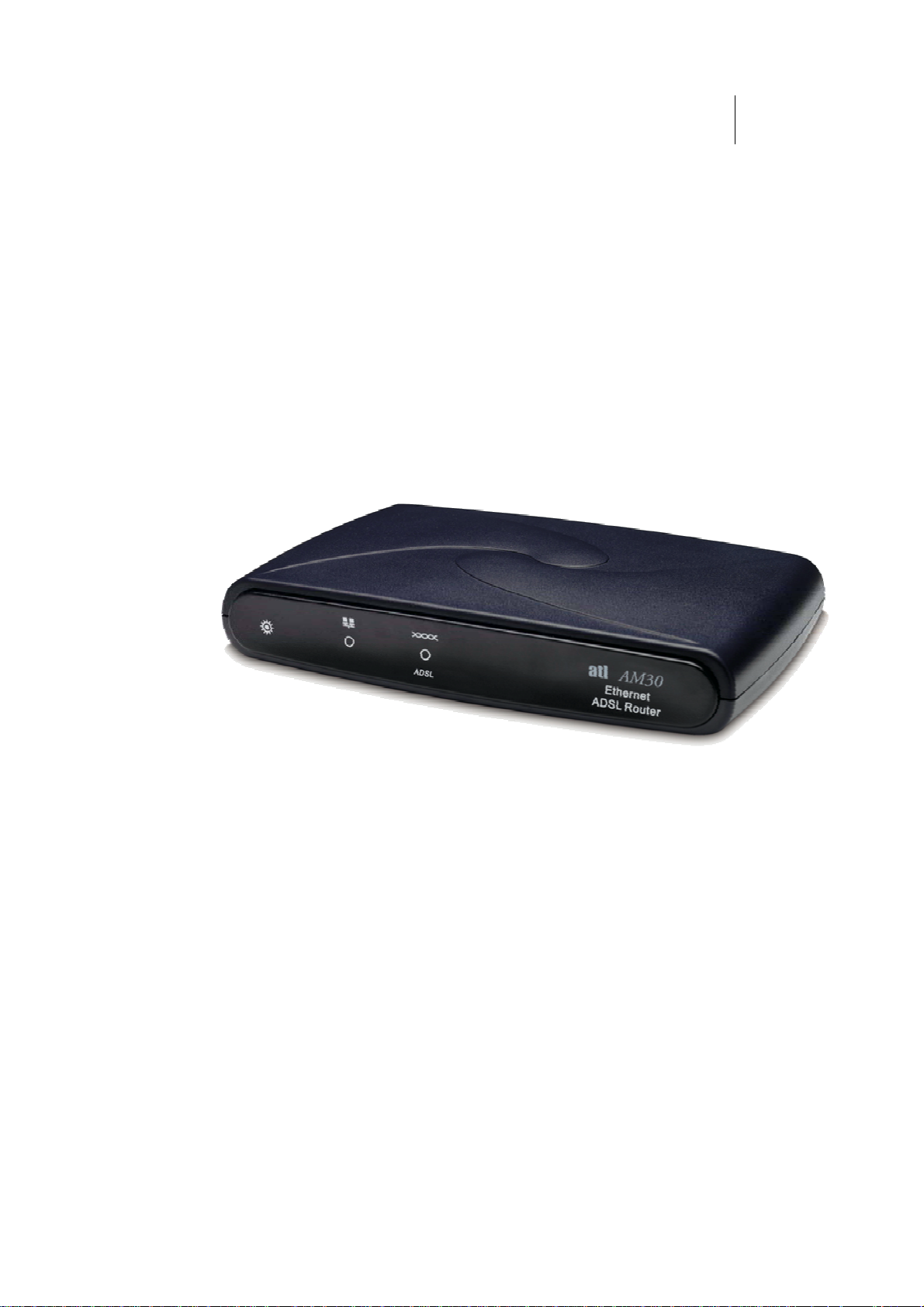
In addition to this document, your AM30 should arrive with the following:
fADSL Ethernet Bridge/Router
fPower adapter
fUSB cable (option)
fEthernet cable (cross-over type)
Standard phone/DSL line cable
AM30
1
1
Fig 1. ADSL Router
Page 12
12
ATL Telecom User Guide
AM30
Front Panel
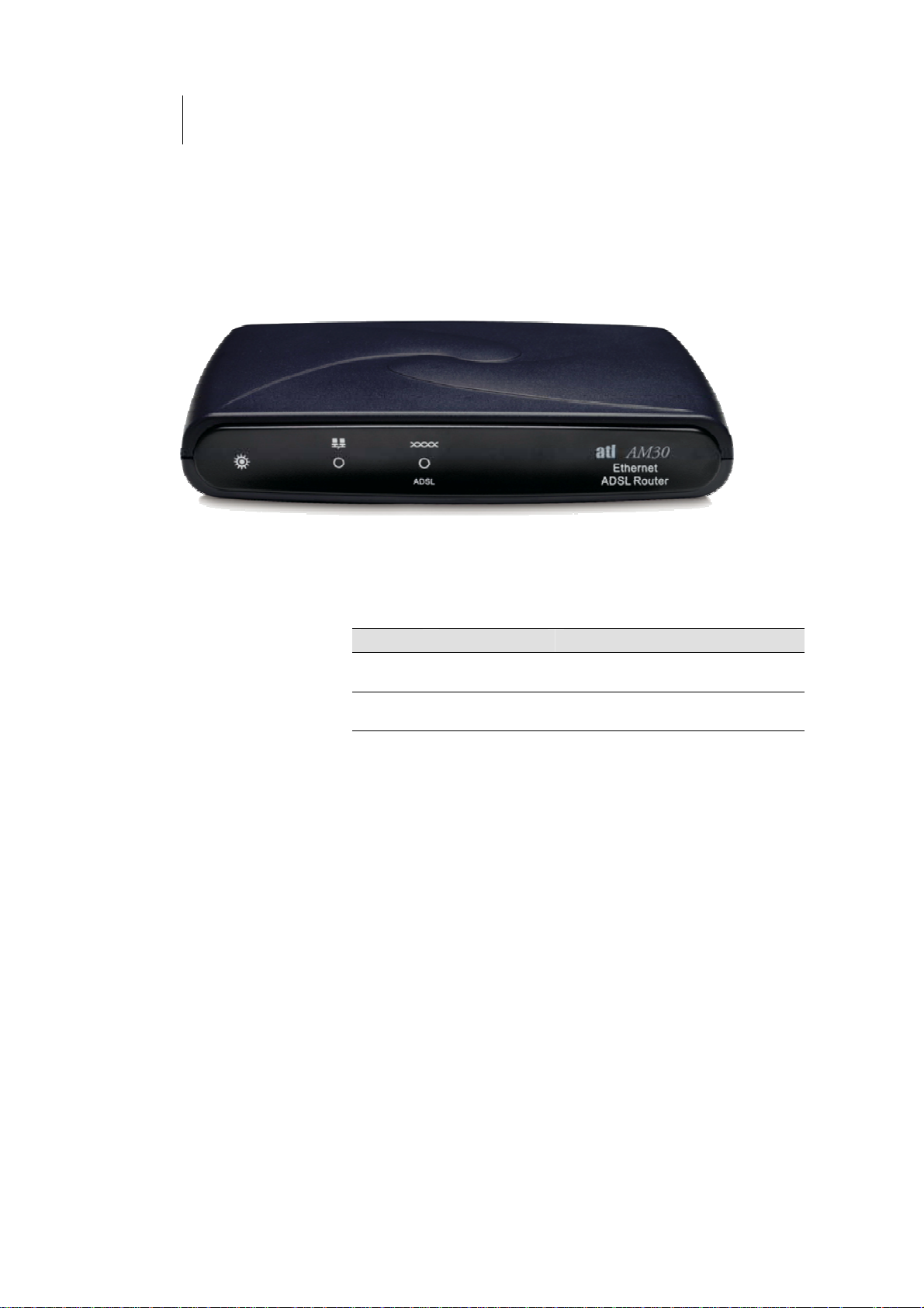
The front panel contains lights called LEDs that indicate the status of the unit.
Figure 2. Front Panel
Label Color Function
PWR green On: Unit is powered on
Off: Unit is powered off
LINK LAN green On: LAN link established and active
Off: No LAN link
ADSL green On: ADSL link establi shed
OFF: No ADSL Link
Page 13
ATL Telecom User Guide
Rear Panel
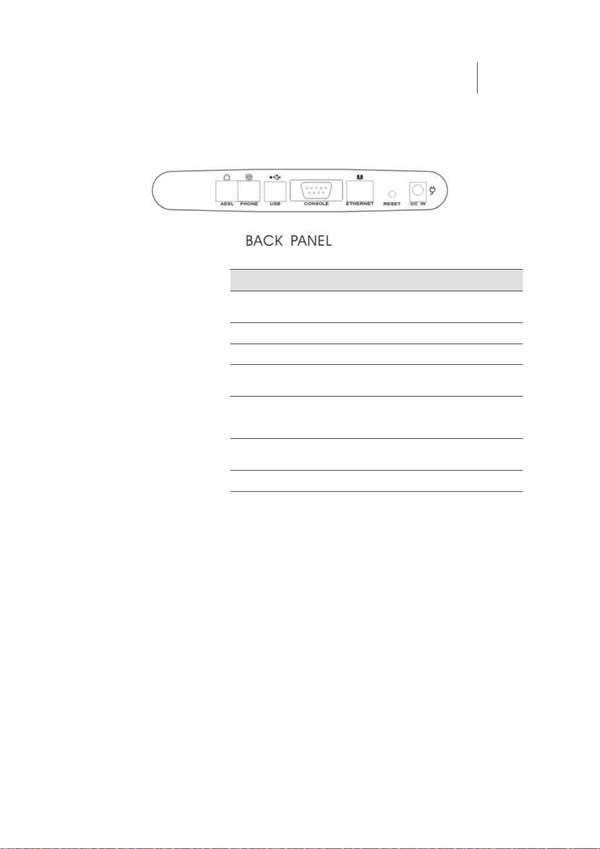
The rear panel contains the ports for the unit's data and power connections.
Figure 3. Rear Panel Connections
Label Function
ADSL Connects the device to a telephone jack for DSL
communication
PHONE Provides an optional connection to your telephone
USB Connects to the USB port on your PC
AM30
1
3
CONSOLE Provides an optional connection to PC’s RS232 port
for CLI
ETHERNET Connects the device to your PC's Ethernet port, or to
the uplink port on your LAN's hub, using the cable
provided
RESET Resets the device to the manufacturer’s default
configuration
DC-IN Connects to the supplied power converter cable
Page 14

Page 15

ATL Telecom User Guide
AM30
1
5
Quick Start
This Quick Start provides basic instructions for connecting the ROUTER to a computer or
LAN and to the Internet.
fPart 1 describes setting up the hardware.
fPart 2 describes how to configure Internet properties
on your computer(s) and how to install the software
for using a computer attached to the USB port.
fPart 3 shows you how to configure basic settings on
the ROUTER to get your LAN connected to the
Internet.
After setting up and configuring the device, you can follow the instructions on page 32 to
verify that it is working properly.
This Quick Start assumes that you have already established ADSL service with your Internet
service provider (ISP). These instructions provide a basic configuration that should be
compatible with your home or small office network setup. Refer to the subsequent chapters
for additional configuration instructions.
Part 1 — Connecting the Hardware
In Part 1, you connect the device to the phone jack, the power outlet, and your computer
or network.
Before you begin, turn the power off for all devices.
These include your computer(s), your LAN hub/switch (if
WARNING
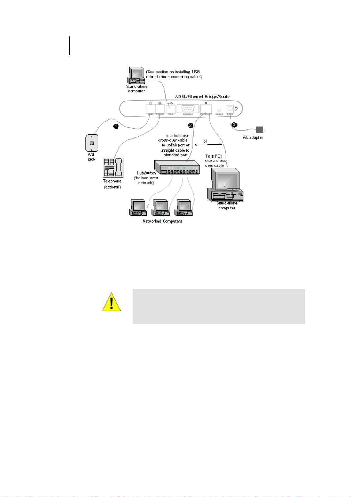
Figure 4 illustrates the hardware connections. The layout of the ports on your device may vary
from the layout shown. Refer to the steps that follow for specific instructions.
applicable), and the ROUTER.
Page 16
16
ATL Telecom User Guide
AM30
Figure 4 Overview of Hardware Connections
Step 1. Connect the ADSL cable and optional telephone.
Connect one end of the provided phone cable to the port labeled ADSL on the rear panel
of the device. Connect the other end to your wall phone jack.
You can attach a telephone line to the device. This is helpful when the ADSL line uses the
only convenient wall phone jack. If desired, connect the telephone cable to the port labeled
PHONE.
Although you use the same type of cable, The ADSL and
PHONE ports are not interchangeable. Do not route the
WARNING
ADSL connection through the PHONE port.
Page 17

ATL Telecom User Guide
AM30
1
7
Step 2. Connect the Ethernet cable.
If you are connecting a LAN to the ADSL/Ethernet router, attach one end of a provided Ethernet
cable to a regular hub port and the other to the Ethernet port on the ROUTER.
If you are using the ROUTER with a single computer and no hub, you must use a “crossover”
Ethernet cable (not provided) to attach the PC directly to the device. The crossover cable is wired
differently than the cable you would use to connect to a hub. When you compare the colored
wires on each end of a straight-through cable, they will be in the same sequence; on crossover
cables, they will not. Contact your ISP for assistance.
Step 3. Attach the power connector.
Connect the AC power adapter to the PWR connector on the back of the device and plug
in the adapter to a wall outlet or power strip.
Step 4. Turn on the ROUTER and power up your systems.
Press the Power switch on the back panel of the device to the ON position.
Turn on and boot up your computer(s) and any LAN devices such as hubs or switches.
Step 5: Install USB software and connect the USB cable.
You can attach a single computer to the device using a USB cable. The USB port is useful if
you have a USB-enabled PC that does not have a network interface card for attaching to
your Ethernet network.
Before attaching the USB cable, you must install a USB driver on your PC and configure the
computer. For complete instructions, see page 25.
Page 18
18
ATL Telecom User Guide
AM30
Part 2 — Configuring Your Computers
Part 2 of the Quick Start provides instructions for configuring the Internet settings on your
computers to work with the ROUTER
Before you begin
By default, the ROUTER automatically assigns all required Internet settings to your PCs. You
need only to configure the PCs to accept the information when it is assigned.
In some cases, you may want to assign Internet information
manually to some or all of your computers rather than allow
Note
the ROUTER to do so. See “Assigning static Internet
information to your PCs” on page 24 for instructions.
fIf you have connected your PC via the USB port, see
the USB configuration instructions on page 25.
fIf you have connected your PC of LAN via Ethernet to
the ROUTER , follow the instructions that correspond
to the operating system installed on your PC.
Windows ® XP PCs
1. In the Windows task bar, click the Start button, and then click
Control Panel.
2. Double-click the Network Connections icon.
3. In the LAN or High-Speed Internet window, right-click on the
icon corresponding to your network interface card (NIC) and
select Properties. (Often, this icon is labeled Local Area
Connection).
The Local Area Connection dialog box displays with a list
of currently installed network items.
4. Ensure that the check box to the left of the item labeled
Internet Protocol TCP/IP is checked, and click
.
5. In the Internet Protocol (TCP/IP) Properties dialog box, click
the radio button labeled Obtain an IP address
automatically. Also click the radio button labeled Obtain
DNS server address automatically.
6. Click
the Control Panel.
twice to confirm your changes, and close
Page 19

ATL Telecom User Guide
AM30
1
9
Page 20
20
ATL Telecom User Guide
AM30
Windows 2000 PCs
First, check for the IP protocol and, if necessary, install it:
1. In the Windows task bar, click the Start button, point to
Settings, and then click Control Panel.
2. Double-click the Network and Dial-up Connections icon.
3. In the Network and Dial-up Connections window, right-click
the Local Area Connection icon, and then select Properties.
The Local Area Connection Properties dialog box displays
with a list of currently installed network components. If
the list includes Internet Protocol (TCP/IP), then the
protocol has already been enabled. Skip to step 10.
4. If Internet Protocol (TCP/IP) does not display as an installed
component, click
5. In the Select Network Component Type dialog box, select
Protocol, and then click
6. Select Internet Protocol (TCP/IP) in the Network Protocols
list, and then click
.
.
.
You may be prompted to install files from your Windows
2000 installation CD or other media. Follow the
instructions to install the files.
7. If prompted, click to restart your computer with
the new settings.
Next, configure the PCs to accept IP information assigned by the ROUTER :
8. In the Control Panel, double-click the Network and Dial-up
Connections icon.
9. In Network and Dial-up Connections window, right-click the
Local Area Connection icon, and then select Properties.
10. In the Local Area Connection Properties dialog box, select
Internet Protocol (TCP/IP), and then click
11. In the Internet Protocol (TCP/IP) Properties dialog box, click
the radio button labeled Obtain an IP address
automatically. Also click the radio button labeled Obtain
DNS server address automatically.
.
12. Click
and then close the Control Panel.
twice to confirm and save your changes,
Page 21
Windows Me PCs
ATL Telecom User Guide
AM30
1. In the Windows task bar, click the Start button, point to
Settings, and then click Control Panel.
2. Double-click the Network and Dial-up Connections icon.
3. In the Network and Dial-up Connections window, right-click
the Network icon, and then select Properties.
2
1
The Network Properties dialog box displays with a list of
currently installed network components. If the list
includes Internet Protocol (TCP/IP), then the protocol has
already been enabled. Skip to step 11.
4. If Internet Protocol (TCP/IP) does not display as an installed
component, click
5. In the Select Network Component Type dialog box, select
Protocol, and then click
6. Select Microsoft in the Manufacturers box.
7. Select Internet Protocol (TCP/IP) in the Network Protocols
list, and then click
.
.
.
You may be prompted to install files from your Windows
Me installation CD or other media. Follow the
instructions to install the files.
8. If prompted, click to restart your computer with
the new settings.
Next, configure the PCs to accept IP information assigned by the ROUTER
9. In the Control Panel, double-click the Network and Dial-up
Connections icon.
10. In Network and Dial-up Connections window, right-click the
Network icon, and then select Properties.
11. In the Network Properties dialog box, select TCP/IP, and
then click
.
12. In the TCP/IP Settings dialog box, click the radio button
labeled Server assigned IP address. Also click the radio
button labeled Server assigned name server address.
13. Click
and then close the Control Panel.
twice to confirm and save your changes,
Page 22

22
ATL Telecom User Guide
AM30
Windows 95, 98 PCs
First, check for the IP protocol and, if necessary, install it:
1. In the Windows task bar, click the Start button, point to
Settings, and then click Control Panel.
2. Double-click the Network icon.
The Network dialog box displays with a list of currently
installed network components. If the list includes TCP/IP,
and then the protocol has already been enabled. Skip to
step 9.
3. If TCP/IP does not display as an installed component, click
.
The Select Network Component Type dialog box displays.
4. Select Protocol, and then click .
The Select Network Protocol dialog box displays.
5. Click on Microsoft in the Manufacturers list box, and then
click TCP/IP in the Network Protocols list box.
6. Click
then click
to return to the Network dialog box, and
again.
You may be prompted to install files from your Windows
95/98 installation CD. Follow the instructions to install
the files.
7. Click to restart the PC and complete the
TCP/IP installation.
Next, configure the PCs to accept IP information assigned by the ROUTER :
8. Open the Control Panel window, and then click the Network
icon.
9. Select the network component labeled TCP/IP, and then
click
.
If you have multiple TCP/IP listings, select the listing
associated with your network card or adapter.
10. In the TCP/IP Properties dialog box, click the IP Address tab.
11. Click the radio button labeled Obtain an IP address
automatically.
12. Click the DNS Configuration tab, and then click the radio
button labeled Obtain an IP address automatically.
13. Click
twice to confirm and save your changes.
You will be prompted to restart Windows.
Page 23
14. Click .
Windows NT 4.0 workstations
First, check for the IP protocol and, if necessary, install it:
1. In the Windows NT task bar, click the Start button, point to
Settings, and then click Control Panel.
2. In the Control Panel window, double click the Network icon.
3. In the Network dialog box, click the Protocols tab.
The Protocols tab displays a list of currently installed
network protocols. If the list includes TCP/IP, then the
protocol has already been enabled. Skip to step 9.
4. If TCP/IP does not display as an installed component, click
.
5. In the Select Network Protocol dialog box, select TCP/IP,
ATL Telecom User Guide
AM30
2
3
and then click
.
You may be prompted to install files from your Windows
NT installation CD or other media. Follow the instructions
to install the files.
After all files are installed, a window displays to inform
you that a TCP/IP service called DHCP can be set up to
dynamically assign IP information.
6. Click to continue, and then click if
prompted to restart your computer.
Next, configure the PCs to accept IP information assigned by the ROUTER :
7. Open the Control Panel window, and then double-click the
Network icon.
8. In the Network dialog box, click the Protocols tab.
9. In the Protocols tab, select TCP/IP, and then click
.
10. In the Microsoft TCP/IP Properties dialog box, click the radio
button labeled Obtain an IP address from a DHCP server.
11. Click
and then close the Control Panel.
twice to confirm and save your changes,
Page 24

24
ATL Telecom User Guide
AM30
Assigning static Internet information to your PCs
In some cases, you may want to assign Internet information to some or all of your PCs
directly (often called “statically”), rather than allowing the ROUTER to assign it. This option
may be desirable (but not required) if:
fYou have obtained one or more public IP addresses
that you want to always associate with specific
computers (for example, if you are using a computer
as a public web server).
fYou maintain different subnets on your LAN (subnets
are described in Appendix 0).
Before you begin, be sure to have the following information on hand, or contact your ISP if
you do not know it:
fThe IP address and subnet mask to be assigned to
each PC to which you will be assigning static IP
information.
fThe IP address of the default gateway for your LAN.
In most cases, this is the address assigned to the LAN
port on the ROUTER . By default, the LAN port is
assigned this IP address: 192.168.1.1. (You can
change this number, or another number can be
assigned by your ISP. See Chapter 0 for more
information.)
fThe IP address of your ISP’s Domain Name System
(DNS) server.
On each PC to which you want to assign static information, follow the instructions on
pages 18 through 23 relating only to checking for and/or installing the IP protocol. Once it
is installed, continue to follow the instructions for displaying each of the Internet Protocol
(TCP/IP) properties. Instead of enabling dynamic assignment of the IP addresses for the
computer, DNS server, and default gateway, click the radio buttons that enable you to
enter the information manually.
Note
Your PCs must have IP addresses that place them in the same
subnet as the ROUTER ’s LAN port. If you manually assign IP
information to all your LAN PCs, you can follow the
instructions in Chapter 0 to change the LAN port IP address
accordingly.
Page 25
ATL Telecom User Guide
AM30
2
5
Connecting a computer to the USB port
If you use the ROUTER’s USB port to connect to a PC, you must install the provided USB driver
software on the PC. The driver enables Ethernet-over-USB communication with the ROUTER .
Configuring the USB computer is a two-part process:
fIn Part 1, you install the USB driver on the PC.
fIn Part 2, you configure the IP properties on the USB
PC.
Part 1. Installing the USB Driver: Ensure that the USB cable is not connected to the USB
port on the PC. The installation program will prompt you when to connect the cable.
12. Copy the USB installation files to a temporary directory on
the USB computer.
13. In the folder where you copied the files, double-click on
setup.exe to start the DSL Modem Setup Wizard.
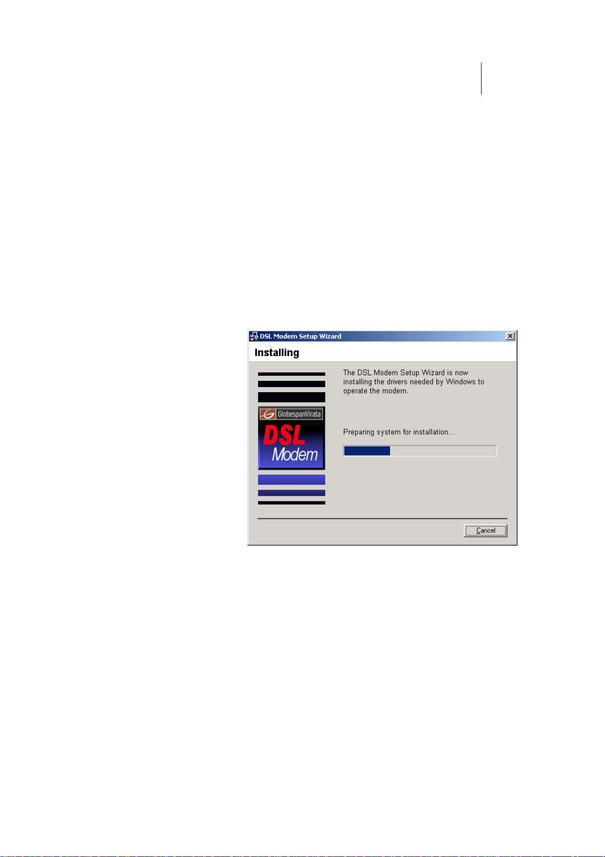
The Installing window displays as the Wizard prepares
your system for the installation, as shown in Figure 5:
Figure 5. USB Setup Wizard: Installing Window
Page 26

26
ATL Telecom User Guide
AM30
If a Microsoft digital signature dialog box displays, click
to continue.
The installation program will begin copying the necessary
installation files to the required locations. When
complete, a window displays to prompt you to connect
the USB cable to your computer.
Figure 7. Prompt for USB Cable Plug-in
14. Connect the USB cable to the Router to your computer.
The USB cable provided has a flat connector on one end
(called Type A) and a square connector on the other
(Type B). Connect the flat connector to your PC and the
square connector to the ROUTER. See Figure 10.
To ADSL-
To PC
Ethernet router
Figure 10. USB Cable Connectors
If a Microsoft digital signature dialog box again displays,
click
A window displays briefly, indicating that the system has
found new hardware, and the Installing window displays
as the installation finishes.
You are now finished installing the driver. You do not need to restart your computer.
Proceed to Part 2 to configure IP properties on the USB PC.
to continue.
Page 27

ATL Telecom User Guide
AM30
2
7
Part 2. Configuring IP properties on the USB PC. Now that the USB driver installation is
complete, you must configure the USB PC so that its IP properties place it in the same
subnet as the ROUTER’s USB port. There are two ways to do this:
he ROUTER is configured tofT assign an appropriate IP
address to the USB PC. If you want to use this
automatic assignment feature, called “DHCP server,”
you must configure the USB PC to accept dynamically
assigned IP information. Follow the instruction on
pages 18 through 23 that correspond to the
operating system installed on your PC.
fIf you want to assign a static IP address to the PC,
follow the instructions on page 24 and use the
following information:
x In the Network and Dial-up Connections window,
be sure to select the icon that corresponds to
your new USB connection (not the one that
corresponds to your Ethernet NIC). When you
display properties for the icon, the following text
should display in the Connect Using text box:
GlobespanVirata USB IAD LAN Modem #n
The USB port on the ROUTER is preconfigurx ed
with these properties:
USB port IP address: 192.168.1.2
USB port subnet mask: 255.255.255.0
Therefore, your PC must be configured as
follows:
IP address: 192.168.1.n where n
is a
number from 2 to
254.
Subnet mask: 255.255.255.0
Default gatewa 192.168.1.2y:
Page 28
28
ATL Telecom User Guide
AM30
Part 3 — Configuring the ROUTER
In Part 3, you log into the program on the ROUTER and configure basic settings for your
Internet connection. Your ISP should provide you with the necessary information to
complete this step.
Logging In to the ROUTER Quick Configuration Page
The ROUTER provides a preinstalled software program called Configuration Manager which
enables you to configure the operation of the device via your Web browser. The settings
that you are most likely to need to change before using the device are grouped onto a
single Quick Configuration page.
Follow these instructions configure the device settings:
1. At any PC connected to the ROUTER via Ethernet or USB,
open your Web browser, and type the following URL in the
address/location box:
192.168.1.1/setup
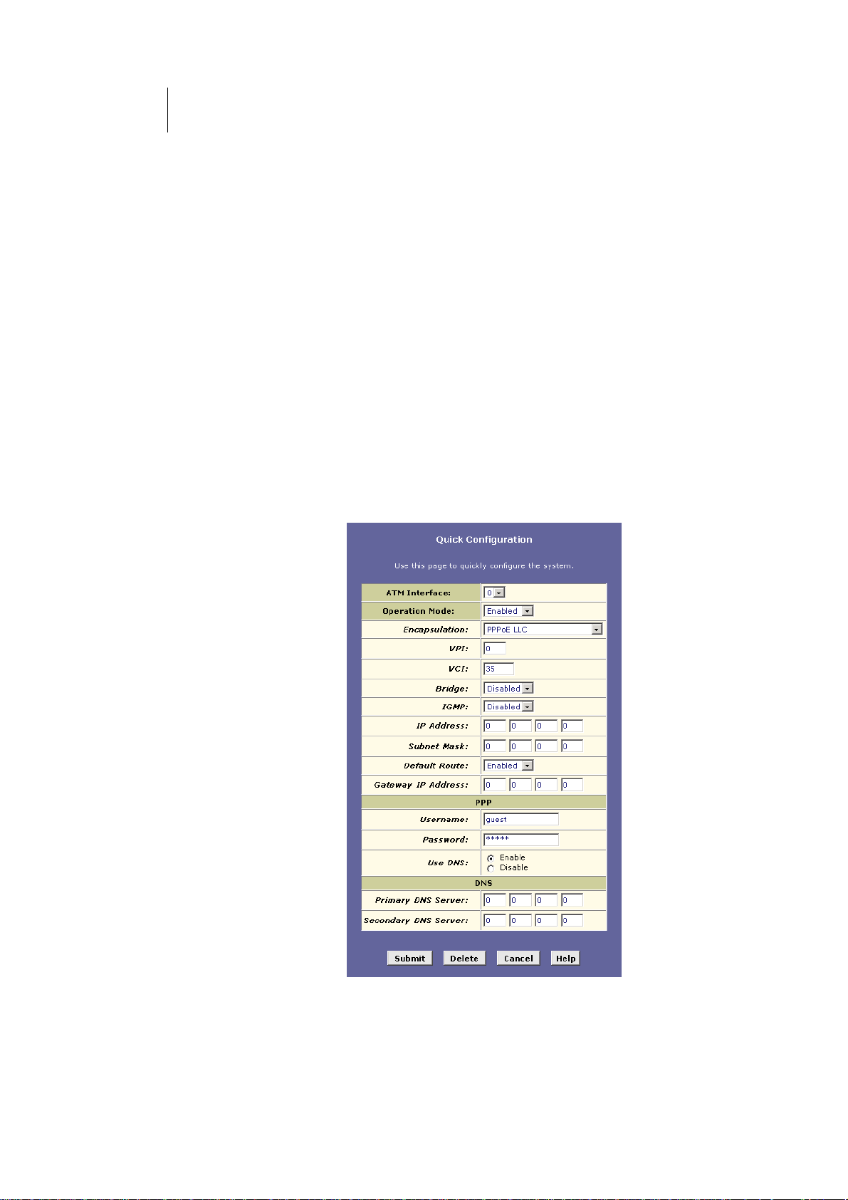
When you press <Return>, the page shown in Figure 13
should display (see Appendix 0, “Troubleshooting,” if
you receive an error message or the page does not
display).
Figure 13. Quick Configuration Page in Configuration Manager
Page 29

ATL Telecom User Guide
AM30
2
The fields are described in the following table. Work with your ISP to determine which
settings you need to change.
Field Description
General Settings
ATM Interface
Operation
Mode
Encapsulation
VCI and VPI
Bridge
IGMP
IP Address and
Subnet Mask
Default Route
Gateway IP
Address
PPP User
Name and
Password
Use DNS
Primary/
Secondary
DNS Server
Select the ATM interface you want to use (usually atm-0).
Your system may be configured with more than one ATM
interface if you are using different types of services with
your ISP.
This setting enables or disables the ROUTER . When set to
“No”, the device cannot be used to provide Internet
connectivity for your network. Set it to “Enabled” now, if
necessary.
This setting determines the type of data link your ISP uses
to communicate with your ADSL/Ethernet router. Contact
them to determine the appropriate setting.
These values are provided by your ISP and determine the
unique path your connection uses to communicate with
your ISP.
This setting enables or disables bridging between the
ROUTER and your ISP. Your ISPs may also refer to this as
“RFC 1483” or “Ethernet over ATM”.
This setting enables or disables the Internet Gr oup
Management Protocol, which some ISPs use to perform
remote configuration of your device.
If your ISP has assigned a public IP address to your LAN,
enter the address and the associated subnet mask in the
boxes provided. (Note: in some configurations, the public
IP address should be entered on your PC rather than on
the ADSL/Ethernet router; check with your ISP.)
When enabled, this setting specifies that the IP address
specified above will be used as the default route for your
LAN. Whenever, one of your LAN computers attempts to
access the Internet, the data will be sent via the WAN
interface.
Specify the IP address that identifies the ISP server
through which your Internet connection will be routed.
PPP Settings
Enter the username and password you use to log in to
your ISP. (Note: this is not the same as the user name and
password you used to log in to Configuration Manager.)
Enable this feature if the DNS server addresses that your
LAN will use should be supplied dynamically each time
you connect to the ISP. If you click Disable, you must
configure DNS addresses manually on each PC or on the
fields below.
DNS Settings
Enter the Primary and Secondary Domain Name System
(DNS) server addresses provided by your ISP.
9
Page 30

30
ATL Telecom User Guide
AM30
2. When finished customizing these settings, click .
The settings are now in effect; however, if you reboot or
if the power is disconnected, your settings will be lost. In
step 3, you save the changes to permanent memory:
3. Click the Admin tab that displays in the upper right of the
page, and then click Commit & Reboot in the task bar.
4. Click
.
A page will display briefly to confirm your changes, and
then you will be returned to the Commit & Reboot page.
You can click
to remove all existing Quick Configuration settings and return to
the default values.
You are now finished customizing basic settings. Read the following section to determine if
you need to change additional settings.
Page 31

ATL Telecom User Guide
AM30
3
1
Default Router Settings
In addition to handling the DSL connection to your ISP, the ADSL/Ethernet router can
provide a variety of services to your network. The device is preconfigured with default
settings for use with a typical home or small office network.
Table 1 lists some of the most important default settings; these and other features are
described fully in the subsequent chapters. If you are familiar with network configuration,
review the settings in Table 1 to verify that they meet the needs of your network. Follow
the instructions to change them if necessary. If you are unfamiliar with these settings, try
using the device without modification, or contact your ISP for assistance.
Before you modifying any settings, review Chapter 0 for general information about
accessing and using the Configuration Manager program. We strongly recommend that
you contact your ISP prior to changing the default configuration.
Table 1. Default Settings Summary
Option Default Setting Explanation/Instructions
DHCP (Dynamic
Host Configuration
Protocol)
NAT (Network
Address Translation)
LAN Port
USB Port
IP Address
DHCP server enabled with the
following pool of addresses:
192.168.1.3
through
192.168.1.34
NAPT rule enabled Your computers’ private IP addresses (see DHC P
Assigned static IP address:
192.168.1.1
Subnet mask:
255.255.255.0
Assigned static IP address:
192.168.1.2
Subnet mask:
255.255.255.0
The ROUTER maintains a pool of private IP addresses
for dynamic assignment to your LAN computers. To
use this service, you must have set up your
computers to accept IP information dynamically, as
described in Part 2 of the Quick Start. See Chapter 0
for an explanation of the DHCP service.
above) will be translated to your public IP address
whenever they access the Internet. See Chapter 5 for
a description of the NAT service.
This is the IP address of the LAN port on the device.
The LAN port connects the device to your Ethernet
network. Typically, you will not need to change this
address. See Chapter 0 for instructions.
This is the IP address assigned to the USB port on the
device (if used). Typically, you will not need to
change this address. See Chapter 0 for instructions.
Page 32

32
ATL Telecom User Guide
AM30
Testing Your Setup
The Quick Start process should enable any computer on your LAN to use the ROUTER’s
ADSL connection to access the Internet.
To test the connection, turn on the device, wait about 30 seconds, and then verify that its
LEDs are illuminated as shown in Table 2.
Table 2. LED Indicators
LED Behavior
PWR
LINK LAN
LINK WAN
If the LEDs illuminate as expected, test your Internet connection from a LAN computer (and
from the USB computer, if applicable): Open your web browser, and type the URL of any
external website (such as http://www.yahoo.com
blinking rapidly and may appear solid as the
If the LEDs do not illuminate as expected or the web page does not display, see Appendix 0
for troubleshooting suggestions. Or, contact your ISP for assistance.
Solid green to indicate that the device is turned on. If this
light is not on, check the power cable attachment.
Solid green to indicate that the device can communicate
with your LAN.
Solid green to indicate that the device has successfully
established a connection with your ISP.
). The LED labeled WAN ACT should be
device connects to the site.
Page 33
ATL Telecom User Guide
AM30
3
3
Getting Started with the Configuration
Manager
The ROUTER includes a preinstalled program called the Configuration Manager, which
provides an interface to the software installed on the device. It enables you to configure the
device settings to meet the needs of your network. You access it through your web browser
from any PC connected to the ROUTER via the LAN or USB ports.
This chapter describes how to use the Configuration Manager.
Accessing the Configuration Manager
The Configuration Manager program is preinstalled into memory on the .ROUTER To access the
program, you need the following:
fA PC or laptop connected to the LAN port on the
device as described in the Quick Start chapter.
fA web browser installed on the PC. The program is
designed to work best with Microsoft Internet
Explorer® version 5.0, Netscape Navigator® version
6.1, or later versions.
You can access the program from any computer connected to the ROUTER via the LAN or
USB ports.
1. From a LAN computer, open your web browser, type the
following URL in the web address (or location) box, and
press <Enter>:
http://192.168.1.1.
Or, from the USB computer, type:
http://192.168.1.2
These are the predefined IP addresses for the LAN and
USB ports on the ROUTER .
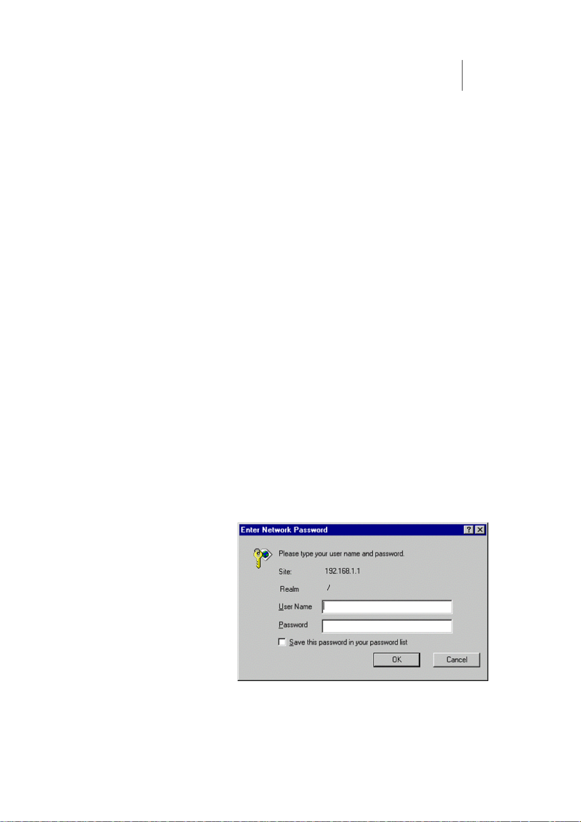
A login screen displays, as shown in Figure 14.
Figure 14. Login Screen
Page 34

34
ATL Telecom User Guide
AM30
Note
2. Enter your user name and password, and then click
.
The first time you log into the program, use these
defaults:
Default User Name:
Default Password:
root
root
You can change the password at any time (See “Configuring
User Names and Passwords” on page 150 for instructions).
The System View page on the Home tab displays each
time you log into the program (shown in Figure 15 on
page 35).
Page 35
ATL Telecom User Guide
AM30
3
5
Functional Layout
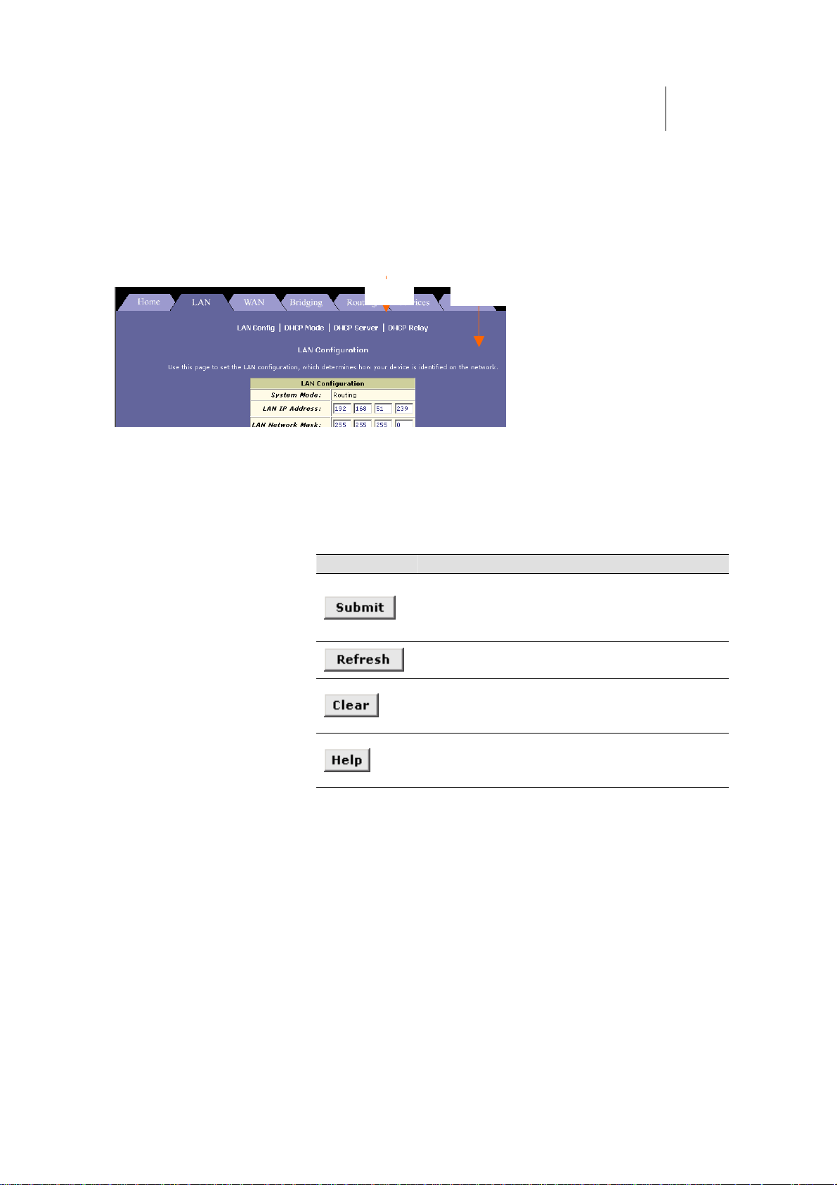
Configuration Manager tasks are grouped into categories, which you can access by clicking
the tabs at the top of each page. Each tab displays the available tasks in a horizontal menu
at the top of the page. You can click on these menu items to display the specific
configuration options.
Tab
Task bar
A separate page displays for each task in the task bar. The left-most task displays by default
when you click on a new tab. The same task may appear in more than one tab, when
appropriate. For example, the Lan Config task displays in both the LAN tab and the Routing
tab.
Commonly used buttons
The following buttons are used throughout the application.
Button Function
Stores in temporary system memory any changes you
have made on the current page. See “Committing
your changes” on page 40 for instructions on storing
changes permanently.
Redisplays the current page with updated
statistics or settings.
On pages that display accumulated statistics,
this button resets the statistics to their initial
values.
Launches the online help for the current
topic in a separate browser window. Help is
available from any main topic page.
Page 36
36
ATL Telecom User Guide
AM30
The Home Page and System View Table
The Home page displays when you first access the program. This page is one of two options
available in the Home tab (the other is the Quick Configuration page, as described on page
28).
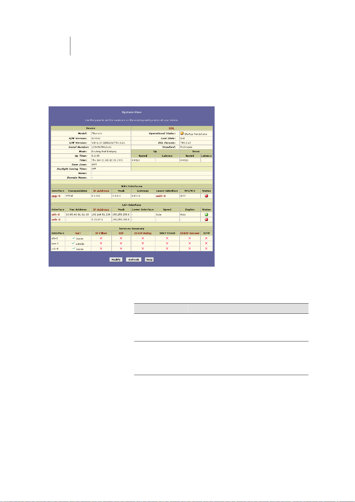
Figure 15. System View Table
The System View table provides a snapshot of your system configuration. Note that some of
the settings are links to the software pages that enable you to configure those settings. The
following table describes each section of the System View table.
Table Heading Description
Device
DSL
Displays basic information about the ROUTER
hardware and software versions, the system
uptime (since the last reboot), and the
preconfigured operating mode.
Displays the operational status, version, and
performance statistics for the DSL line. You can
on DSL in the table heading or display the WAN
tab to view additional DSL settings, which are
described in Chapter 0.
Page 37

Table Heading Description
ATL Telecom User Guide
AM30
3
7
WAN Interfaces
LAN Interfaces
Services Summary
Displays the software name(s) and various
settings for the device interface(s) that
communicates with your ISP via DSL. Although
you only have one physical DSL port, multiple
software-defined interfaces can be configured to
use it. See the ATM VC, PPP, EOA, and IPoA
chapters (Chapters 0, 0, 0, and 13, respectively)
for more information about the WAN interfaces
defined on your system.
For each interface, a "Lower Interface" name,
such as aal5-0, should display. You can click on
the lower interface name to view or change the
ATM VC settings that this interface uses.
Displays the software names and various settings
for the device interfaces that communicate
directly with your network. These typically include
an Ethernet interface named eth-0, and may
include a USB interface named usb-0. For
information on modifying properties of these
interfaces, see Chapter 0.
Displays the status of various services that the
ROUTER performs to help you manage your
network. A green check mark indicates the
service is active and a red X indicates that it is
inactive:
NAT:o Translating private IP addresses to your
public IP address (Chapter 0).
IP Filter: Setting up filtering rulo es that accept
or deny incoming or outgoing data
(Chapter 0).
o RIP: Enabling router-to-router
communication (Chapter 0).
o DHCP Relay: Enabling dynamic assignment
of IP information from your ISP to your
computers (Chapter 0).
o DHCP Client: Enabling dynamic assignment
of IP information from your ISP or another
computer on your network to the device’s
LAN port (Chapter 0).
o DHCP Server: Enabling dynamic assignment
of IP information from the device’s built-in
DHCP server to your LAN computers
(Chapter 0).
IGMP: Enablino g message forwarding from
external sources such as your ISP, based on
Internet Group Management Protocol (not
configurable).
Page 38
38
ATL Telecom User Guide
AM30
Modifying Basic System Information
You can modify basic system information, which includes the system date and time and the
names assigned to the ROUTER and the network domain in which it exists.
Changing the ROUTER date and time does not affect the
Note
Follow these instructions to change basic system information:
date and time on your PCs.
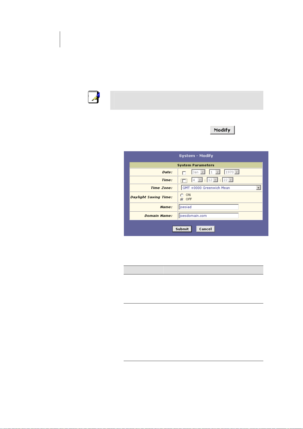
1. At the bottom of the Home page, click .
The System - Modify page displays in a separate browser
window:
Figure 16. System - Modify Page
2. Modify the fields on this page as required. The following
table describes each field:
Option Description
Date and Time
Time Zone,
Daylight Savings
Time
These fields initially appear dimmed. To modify
the date and time, click the respective check
boxes and select the appropriate values from
the drop-down lists. The time displays in military
format.
You can select your time zone from the dropdown list, and then click the appropriate radio
button to indicate whether Daylight Savings
Time is currently in effect.
After you initially set the time, turning DST on
or off will adjust the current displayed time by
one hour in the appropriate direction.
You must remember to change the DST option
each spring and fall — it will not change
automatically.
Page 39
Option Description
ATL Telecom User Guide
AM30
3
9
Name
Domain Name
You can use this field to specify an easy-toremember name for the ADSL-Ethernet router.
The next time you want to access Configuration
Manager, you can type this name in the
location box in your Web browser, instead of
typing the numeric IP address. For example, if
you entered myrouter in this field (and left the
Domain Name field blank), then you could type
the following in your Web browser to access
Configuration Manager:
http://myrouter
(Note: this will only work if you are using the
ROUTER’s DNS relay feature. This feature is
automatically enabled when the DNS server
address configured on your PCs is also the
address assigned to the LAN port on the
ROUTER. See Chapter 0 for more information.
You can use this field to specify an Internet
domain name for the ADSL-Ethernet router. The
next time you access Configuration Manager,
you can type the domain name and the device
name (see the Name field above) in your Web
browser. For example, if you entered myrouter
in the Name field and mydomain.com in the
Domain Name field, then you would type the
following in your Web browser to access
Configuration Manager:
http://myrouter.mydomain.com
3. When you are finished modifying the settings, click
, and then click to return to the System
View page.
4. To save your changes to permanent memory, click the
Admin tab, and then click
5. Click
.
Commit & Reboot in the task bar.
Page 40
40
ATL Telecom User Guide
AM30
Committing Changes and Rebooting
Committing your changes
Whenever you use the Configuration Manager to change system settings, the changes are
initially placed in temporary storage called random access memory or RAM. Your changes are
made effective when you submit them, but will be lost if the device is reset or turned off.
You can commit changes to save them permanently to flash memory.
Submitting changes activates them immediately, but saves
Note
Follow these steps to commit changes.
them only until the device is reset or powered down.
Committing changes saves them permanently.
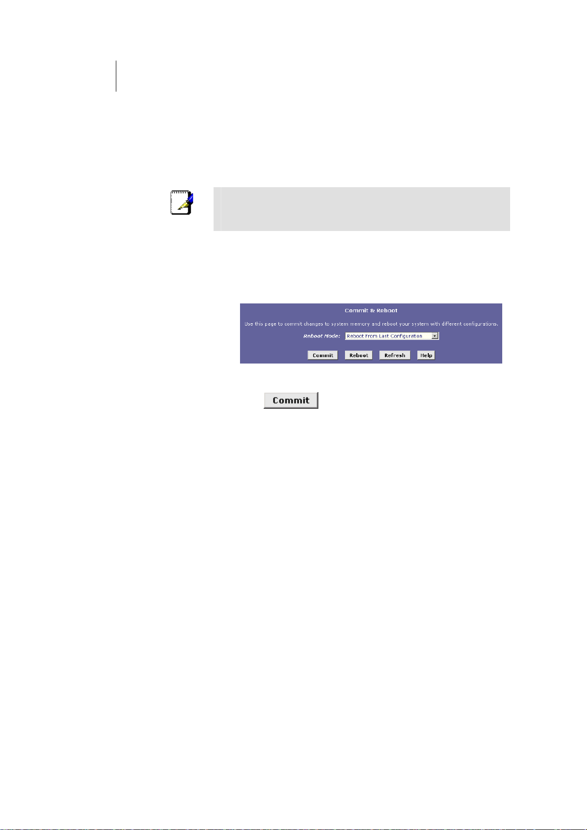
1. Click the Admin tab, and then click Commit & Reboot in the
task bar.
The Commit & Reboot page displays:
Figure 18. Commit & Reboot Page
2. Click . (Disregard the selection in the Reboot
Mode drop-down list; it does not affect the commit process.)
The changes are saved to permanent storage.
The previous settings are copied to backup storage so
that they can be recalled if your new settings do not
work properly (see the rebooting instructions on page
41).
Page 41
ATL Telecom User Guide
AM30
4
Rebooting the device using Configuration Manager
To reboot the device, display the Commit & Reboot page, select the appropriate reboot
1
mode from the drop-down menu, and then click
.
You can select from the following three options when rebooting:
Option Description
Reboot from Last
Configuration
Reboot from Backup
Configuration
Reboot from Default
Configuration
Reboots the device using the current settings in
permanent memory, including any changes you
just committed.
Reboots the device using settings stored in
backup memory. These are the settings that were
in effect before you committed new settings in
the current session.
Reboots the device to default settings provided
by your ISP or the manufacturer. Choosing this
option erases any custom settings.
Do not reboot the device using the Reset button on the
back panel of the ROUTER to activate new changes. This
WARNING
button resets the device settings to the manufacturer’s
default values. Any custom settings will be lost.
Page 42

Page 43

ATL Telecom User Guide
AM30
4
3
Configuring the LAN and USB Ports
This chapter describes how to configure IP properties for the interfaces on the
ADSL/Ethernet router that communicate with your LAN and USB computers.
Connecting via Ethernet and/or USB
If you are using the ADSL/Ethernet router with multiple PCs on your LAN, you must connect
the LAN via an Ethernet hub to the device's LAN port, called eth-0.
If you are using a single PC with the ADSL/Ethernet router, you have two options for connecting it
to the device:
fYou can connect the PC directly to the LAN port
using a crossover Ethernet cable. See Appendix 0,
“Troubleshooting“ for a description of crossover
versus straight-through Ethernet cables.
fIf the PC is USB-enabled, you can connect it directly
to the device's USB port, called usb-0. Only one
computer can be connected in this manner.
You can also use the USB and Ethernet ports simultaneously, connecting your LAN to the
Ethernet port and a standalone PC to the USB port.
You must assign a unique IP address to each device port that you use.
Page 44
44
ATL Telecom User Guide
AM30
Configuring the LAN Port IP Address
The LAN IP address identifies the LAN port (eth-0) as a node on your network; that is, its IP
address must be in the same subnet as the PCs on your LAN.
A network node can be thought of as any interface
where a device connects to the network, such as the
Definition
You can change the default to reflect the set of IP addresses that you want to use with your
network.
If your network uses a DHCP server (other than the ADSL/Ethernet router) to assign IP
addresses, you can configure the device to accept and use a LAN IP address assigned by that
server. Similarly, if your ISP performs DHCP serving for your network, you can configure the
device to accept an IP address assigned from the ISP’s server. In this mode, the ADSL/Ethernet
router is considered a DHCP client of your (or your ISP’s) DHCP server.
Note
ROUTER’s LAN port and the network interface cards on
your PCs. See Appendix 0 for an explanation of subnets.
The ROUTER itself can function as a DHCP server for your
LAN computers, as described in Chapter 0, but not for its
own LAN port.
Follow these steps to change the default LAN IP address or to configure the LAN port as a
DHCP client:
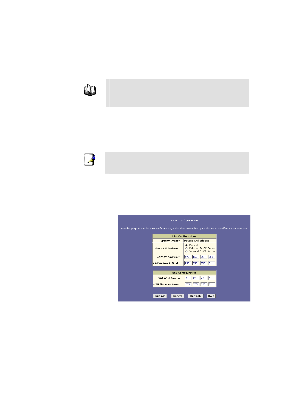
1. Log into Configuration Manager, and then click the LAN tab.
The LAN Configuration page displays, as shown in Figure
19.
Figure 19. LAN Configuration Page
Page 45

ATL Telecom User Guide
AM30
The LAN Configuration table displays the following
settings:
Setting
System Mode
Get LAN
Address
LAN IP Address
and Network
Mask
Description
The preconfigured mode for your device, such as
Routing mode, Bridging mode, or both modes
simultaneously. This setting is not user -configurable.
Provides options for how the device’s LAN port is
assigned an IP address:
Manual indicates tho at you will be assigning a
static IP address, which you can enter in the
fields below.
o External DHCP Server indicates that your ISP will
be assigning an IP address from their own DHCP
server to the port, dynamically each time you log
on.
o Internal DHCP Server indicates that you have a
DHCP server device on your network that will
assign an address to the port.
u choose either the internal or eIf yo xternal server
option, the LAN port is called a DHCP client of the
server.
Note that the public IP address assigned to you by
your ISP is not your LAN IP address. The public IP
address identifies the WAN (ADSL) port on your
ADSL/Ethernet router to the Internet.
The IP address and network mask for the port. See
Appendix 0 for and overview of IP addresses and
masks.
4
5
2. Enter an IP address and mask in the fields provided and
choose Disabled in the Use DHCP field, or enable either a
remote or local DHCP server. Keep these points in mind:
fManually specifying an address: If you are using
routing services on you LAN such as DHCP and NAT,
you will want to assign a fixed LAN IP address and
mask. This ensures that your LAN computers have a
fixed address that they use to communicate with the
device.
The IP address you assign must be in the same subnet
as your LAN computers that connect to this port (that
is, the network ID portion of their IP addresses and
their subnet masks must be the same). See Appendix
0 for an explanation of IP addresses and network
masks.
If you change the LAN IP address, you may need to
update the DHCP configuration so that the addresses
that the DHCP server dynamically assigns to your
computers are on the same subnet as the new LAN IP
address. See Chapter 0 for instructions on changing
the pool of dynamically assigned addresses.
Page 46

46
ATL Telecom User Guide
AM30
fEnabling DHCP: If you choose to have the LAN port
be a DHCP client of an internal or external server, the
LAN Network Mask field will be dimmed and made
unavailable for entry. The LAN IP Address field will
remain editable, however. The address that you
specify here will be used as a request to the DHCP
server. This is referred to as a "Configured IP
Address" in the program. If the configured IP address
is not available from the DHCP server, then system
will accept another assigned address. Even after
another number is assigned, the same configured IP
address will continue to display in this field.
3. Click .
fIf you changed the LAN IP address while working
from a PC that is connected to the device via
Ethernet, then your connection will be terminated.
fIf you changed the LAN IP address while working
from a PC connected to the device via USB, a page
will display to confirm your change and your
connection will remain active.
fIf you enabled the DHCP service, the ADSL/Ethernet
router will initiate a request for an IP address from
your LAN's DHCP server. If a different IP address is
assigned than was previously configured, your
current connection will be terminated.
4. Reconfigure your PCs, if necessary, so that their IP
addresses place them in the same subnet as the new IP
address of the LAN port. See the Quick Start chapter, “Part 2
— Configuring Your Computers,” for instructions.
5. Log into Configuration Manager by typing the new IP
address in your Web browser’s address/location box.
6. If the new settings work properly, click the Admin tab, and
then click
7. Click
memory.
Commit & Reboot in the task bar.
to save your changes to permanent
Page 47

Configuring the USB Port IP Address
1. If the LAN Configuration page is not already displaying,
click the LAN tab.
If the USB Configuration table does not display below
the LAN Configuration table, then your system does not
currently support USB functionality. Contact your ISP for
assistance.
2. In the USB Configuration table, enter the IP Address and
Network Mask for the USB port.
The IP address must place the USB port in the same
subnet as the USB computer. The USB port and USB
computer can also be in the same subnet as the LAN port
and the computers attached to it.
For example, if the LAN and USB ports are assigned
addresses 192.168.1.1 and 192.168.1.2, respectively,
then the PCs attached to either port can be assigned
addresses in the range 192.168.1.3 through
192.168.1.255.
ATL Telecom User Guide
AM30
4
7
3. Click .
fIf you changed the USB port IP address while working
from the USB-attached computer, then the
connection will be terminated.
fIf you were using the Ethernet interface, a page will
display to confirm your change and your connection
will remain active.
4. If necessary, reconfigure your USB PC so that its IP address
places it in the same subnet as the new IP address of the
USB port. See the Quick Start chapter, “Part 2 —
Configuring Your Computers,” for instructions.
5. Log into Configuration Manager by typing the new USB port
IP address in your Web browser’s address/location box.
6. If the new settings work properly, click the Admin tab, and
then click
7. Click
memory.
Commit & Reboot in the task bar.
to save your changes to permanent
Page 48

Page 49
ATL Telecom User Guide
AM30
4
9
Viewing System IP Addresses and IP
Performance Statistics
The interfaces on the ROUTER that communicate with other network and Internet devices
are identified by unique Internet protocol (IP) addresses. You can use the Configuration
Manager to view the list of IP addresses that your device uses, and to view other system
and network performance data.
See Appendix 0 for a description of IP addresses and masks.
Viewing the ROUTER’s IP Addresses
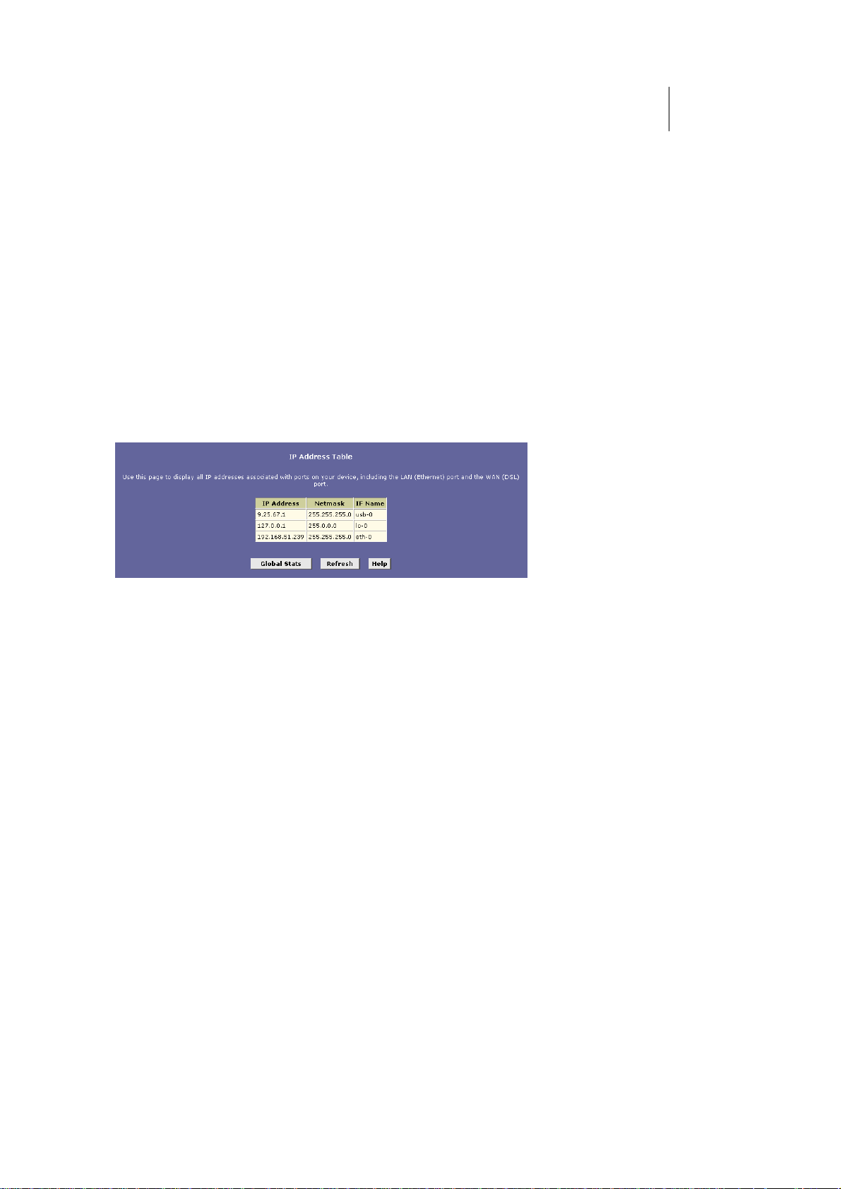
To view the ROUTER’s IP addresses, click the Routing tab, and then click IP Addr in the task
bar. The IP Address Table page displays, as shown in Figure 20:
Figure 20. IP Address Table Page
The table lists the IP addresses, network masks (“Net Mask”), and interface names (“IF
Name”) for each of its IP-enabled interfaces.
The listed IP addresses may include:
fThe IP address of the device’s LAN (Ethernet) port,
called eth-0. See Chapter 0 for instructions on
configuring this address.
fThe IP address of the device’s USB port, named usb-
0. See Chapter 0 for instructions on configuring this
address.
fThe IP address of the WAN (ADSL line) interface,
which your ISP and other external devices use to
identify your network. It may be identified in the
Configuration Manager by the names ppp-0, eoa-0,
or ipoa-0, depending on the protocol your device
uses to communicate with your ISP. Your ISP may
assign the same address each time, or it may change
each time you reconnect.
fThe “loopback” IP address, named lo-0, of
127.0.0.1. This special address enables the device to
keep any data addressed directly to it, rather than
route the data through the WAN or LAN ports.
If your device has additional IP-enabled interfaces, the IP addresses of these will also display.
Page 50
50
ATL Telecom User Guide
AM30
Viewing IP Performance Statistics
You can view statistics on the processing of Internet protocol packets (a packet is a
collection of data that has been bundled for transmission). You will not typically need to
view this data, but you may find it helpful when working with your ISP to diagnose network
and Internet data transmission problems.
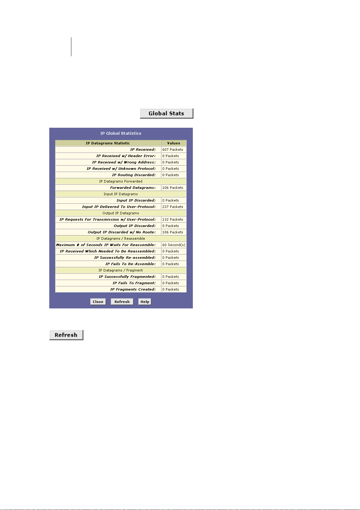
To view global IP statistics, click
shows the IP Global Statistics page:
on the IP Address Table page. Figure 21
Figure 21. IP Global Statistics Page
To display updated statistics showing any new data since you opened the page, click
.
Page 51
ATL Telecom User Guide
AM30
5
1
Configuring Dynamic Host Configuration
Protocol
You can configure your network and ROUTER to use the Dynamic Host Configuration
Protocol (DHCP). This chapter provides an overview of DHCP and instructions for
implementing it on your network.
Overview of DHCP
What is DHCP?
DHCP is a protocol that enables network administrators to centrally manage the assignment
and distribution of IP information to computers on a network.
When you enable DHCP on a network, you allow a device — such as the ROUTER or a
router located with your ISP — to assign temporary IP addresses to your computers
whenever they connect to your network. The assigning device is called a DHCP server, and
the receiving device is a DHCP client.
If you used the Quick Start instructions, you configured
each LAN PC with an IP address, or you specified that it will
receive IP information dynamically (automatically). If you
Note
The DHCP server draws from a defined pool of IP addresses and “leases” them for a
specified amount of time to your computers when they request an Internet session. It
monitors, collects, and redistributes the addresses as needed.
On a DHCP-enabled network, the IP information is assigned dynamically rather than
statically. A DHCP client can be assigned a different address from the pool each time it
reconnects to the network.
chose to have the information assigned dynamically, then
you configured your PCs as DHCP clients that will accept IP
addresses assigned from a DCHP server such as the
ROUTER .
Why use DHCP?
DHCP allows you to manage and distribute IP addresses throughout your network from a
central computer. Without DHCP, you would have to configure each computer separately
with IP addresses and related information. DHCP is commonly used with large networks
and those that are frequently expanded or otherwise updated.
Page 52
52
ATL Telecom User Guide
AM30
ROUTER DHCP modes
The device can be configured as a DHCP server, relay agent or client.
fIf you configure the device as a DHCP server it will
maintain the pool of addresses and distribute them
to your LAN computers. If the pool of addresses
includes private IP addresses, you must also configure
the Network Address Translation service, so that the
private addresses can be translated to your public IP
address on the Internet.
fIf your ISP performs the DCHP server function for
your network, then you can configure the device as a
DHCP relay agent. When the ROUTER receives a
request for Internet access from a computer on your
network, it contacts your ISP for the necessary IP
information, and then relays the assigned
information back to the computer.
fIf you have another PC or device on your network
that is already performing the DHCP server function,
then you can configure the device’s LAN port to be a
DHCP client of that server (as are your PCs). This
configuration is described in Chapter 0.
Note
You can input settings for both DHCP server and DHCP
relay mode, and then activate either mode at any time.
Deactivated settings are retained for your future use.
Page 53

ATL Telecom User Guide
AM30
5
3
Configuring DHCP Server
Before you begin, be sure to configure your PCs to accept
DHCP information assigned by a DHCP server. For detailed
Note
instructions, see the Quick Start chapter, “Part 2 —
Configuring Your Computers.”
To set up DHCP server, you first define the ranges of IP addresses that you want to be
distributed to your PCs, called DHCP server address pools.
Guidelines for creating DHCP server address pools
IP address pools can contain multiple public addresses that you have purchased from your
ISP, but are typically private addresses that you create. LAN administrators often create
private IP addresses for use only on their networks. See “Overview of NAT” on page 61 for
an explanation of private IP addresses.
You can create up to two pools. The pools can maintain a combined total of 254 IP
addresses. For example, you could configure only one pool with addresses in the range
192.168.1.2 through 192.168.1.255, or two pools with the following address ranges:
Pool 0: 192.168.1.2 through 192.168.1.128
Pool 1: 192.168.1.129 through 192.168.1.255
The same pool can be used for distributing IP addresses to your LAN PCs (connected via the
Ethernet port) and a USB-connected computer, as long as these ports are in the same
subnet. You may want to create a second pool if any of these circumstances apply:
fThe device’s Ethernet (eth-0) and USB (usb-0) ports
are in different subnets (note that different subnets
are not required). See Appendix 0 for an explanation
of subnets.
fYour LAN configuration includes two subnets.
fYou have only one subnet, but the addresses you
want to distribute are not in a continuous range.
(Alternatively, you can exclude particular addresses
from distribution from a single pool; see page 57.)
The DHCP server will distribute addresses to computers connected to a given device
interface only when that interface is in the same subnet as the pool addresses. For example,
assume that the Ethernet and USB interfaces are assigned IP addresses that place them in
two different subnets, as shown:
Ethernet interface (eth-0): IP address 192.168.1.1
mask 255.255.255.0
USB interface (usb-0): IP address 192.168.2.1
mask 255.255.255.0
Page 54
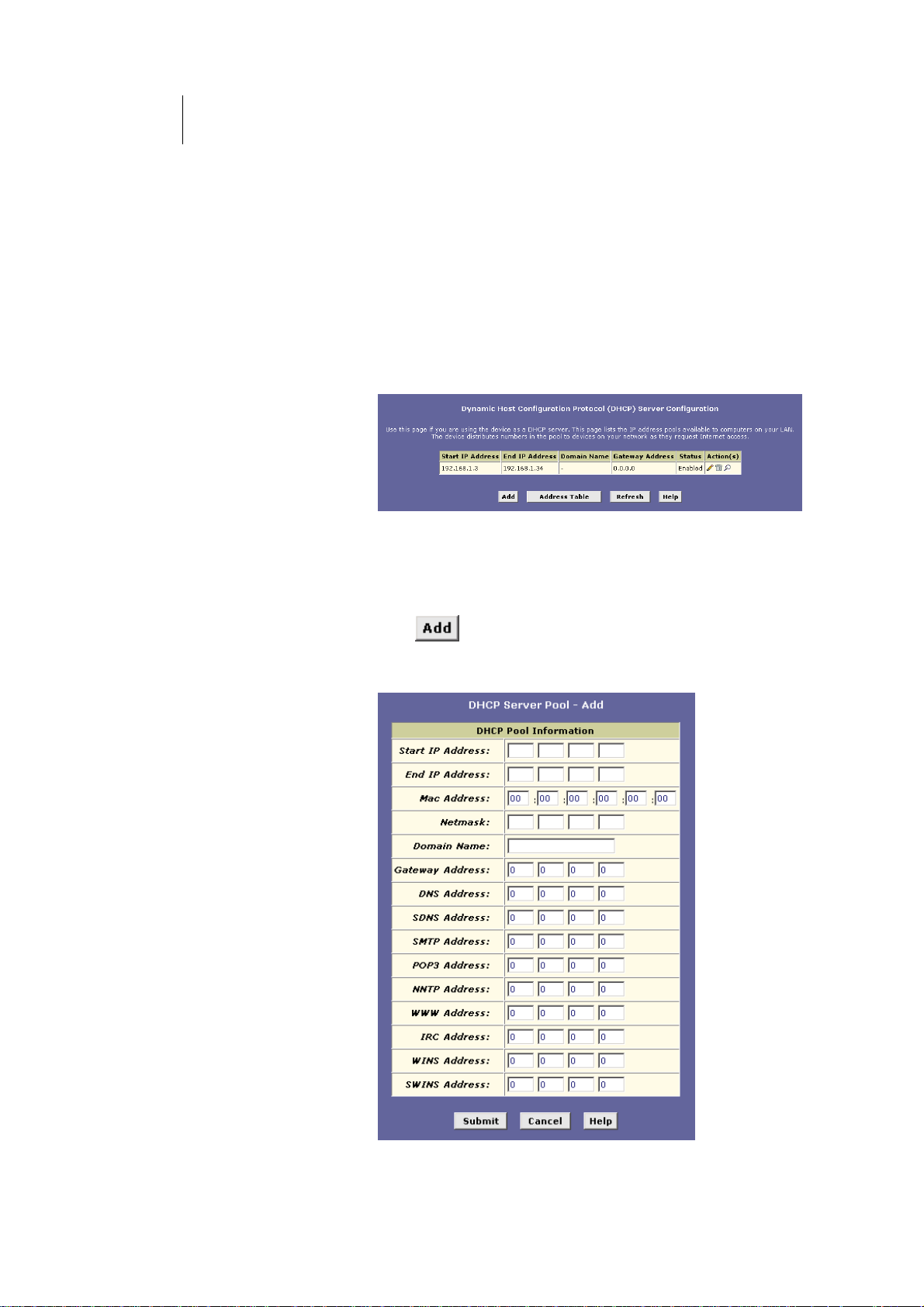
54
ATL Telecom User Guide
AM30
With this configuration, you could create the following two pools:
Pool 0: 192.168.1.2 through 192.168.1.11
Pool 1: 192.168.2.2 through 192.168.2.2
The DHCP server would automatically distribute the Pool 0 addresses only to computers
connected to the interface in the same subnet as these addresses—the LAN interface, eth-
0. Likewise, the address in Pool 1 would be distributed to the USB-connected computer.
Adding DHCP Server Address Pools
Follow these instructions to create an IP address pool:
1. Log into Configuration Manager, click the LAN tab, and then
click DHCP Server in the task bar.
The DHCP Server Configuration page displays:
Figure 22. DHCP Configuration Page
Depending on your preconfigured settings, the table may
display one or more address pools, each in a row, or may
be empty.
2. Click .
The DHCP Server Pool – Add page displays, as shown in
Figure 23.
Page 55

ATL Telecom User Guide
AM30
Figure 23. DHCP Server Pool – Add Page
3. Enter values for the Start IP Address, End IP Address, and
Net Mask fields, which are required, and any others as
needed:
5
5
Field Description
Start/End IP
Addresses
Specifies the lowest and highest
addresses in the pool, up to a
maximum range of 254 addresses. For
example, if the LAN port is assigned IP
address 192.168.1.1, then you could
create a pool with address range
192.168.1.2 – 192.168.1.254 for
distribution to your LAN computers.
Mac Address
A MAC address is a manufacturerassigned hardware ID that is unique
for each device on a network. Use this
field only if you want to assign a
specific IP address to the computer
that uses this MAC address. If you
type a MAC address here, you must
have specified the same IP address in
both the Start IP Address and End IP
Address fields.
Net Mask
Specifies which portion of each IP
address in this range refers to the
network and which portion refers to
the host (computer).For a description
of network masks and LAN network
masks, see Appendix 0. You can use
the network mask to distinguish
which pool of addresses should be
distributed to a particular subnet (as
explained on page 53.
Domain Name
A user-friendly name that refers to the
subnet that includes the addresses in
this pool. This is used for reference
only.
Gateway
Address
The address of the default gateway
for computers that receive IP
addresses from this pool. If no value is
specified, then the appropriate LAN
(eth-0) or USB (usb-0) port address on
the device will be distributed to each
PC as its gateway address, depending
on how each is connected.
See “Hops and gateways” on page 84
for an explanation of gateway
addresses.
Page 56

56
ATL Telecom User Guide
AM30
Field Description
DNS/SDNS
Address
The IP address of the Domain Name
System server and Secondary Domain
Name System server to be used by
computers that receive IP addresses
from this pool. These DNS servers
translate common Internet names that
you type into your web browser into
their equivalent numeric IP addresses.
Typically, these servers are located
with your ISP.
SMTP...SWINS
(optional)
The IP addresses of devices that
perform various services for
computers that receive IP addresses
from this pool (such as the SMTP, or
Simple Mail Transfer Protocol, server
which handles e-mail traffic). Contact
your ISP for these addresses.
4. When you are done defining the pool, click .
A confirmation page displays briefly to indicate that the
pool has been added successfully. After a few seconds,
the DHCP Server Pool – Add page displays with the
newly added pool.
5. Follow the instructions in “Setting the DHCP Mode” on
page 60 to enable the DHCP Server.
Page 57
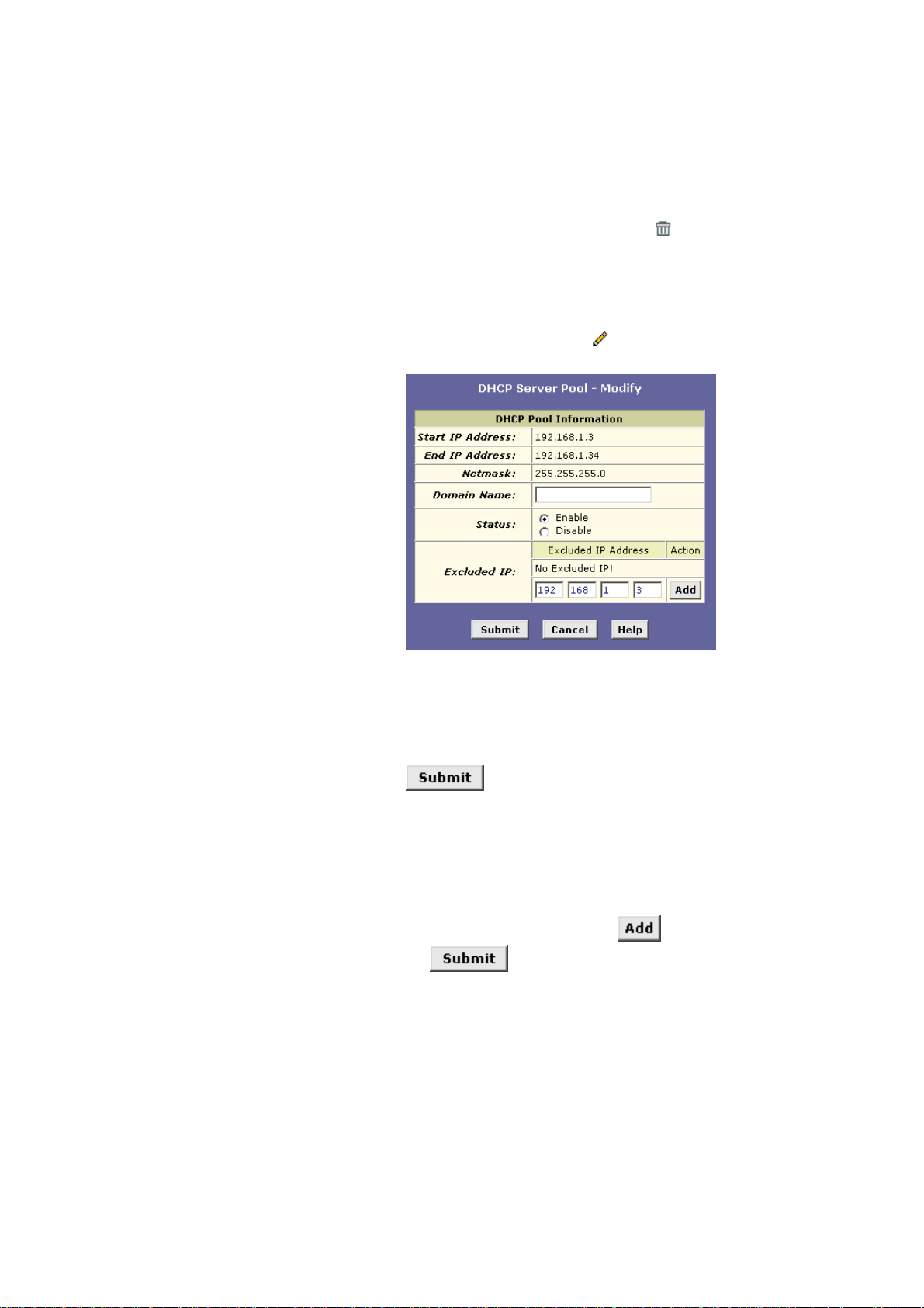
ATL Telecom User Guide
AM30
5
7
Viewing, modifying, and deleting address pools
To view, modify, or delete an existing address pool, display the DHCP Server Configuration
page, and click the icons in the corresponding row in the address pool table.
fTo delete an IP address pool, click
and commit your changes.
fTo view details on an IP address pool, click . A page
displays with the same information that you entered
when you added the pool.
fTo modify the pool, click
. The DHCP Server Pool –
Modify page displays, as shown in Figure 24.
, then submit
Figure 24. DHCP Server Pool – Modify Page
You can change the domain name associated with an
IP address pool or enable/disable the pool. By default,
a pool is enabled when you create it.
When you are done making modifications, click
. Use the Commit function to save your
changes to permanent memory (see page 40).
Excluding IP addresses from a pool
If you have IP addresses that are designated for fixed use with specific devices, or for some
other reason you do not want to make them available to your network, you can exclude
them from the pool. Display the DHCP Server Pool – Modify page, as shown in Figure 24.
Type each address to be excluded in the Excluded IP field, and click
done specifying excluded addresses, click
, and then use the Commit function to
save your changes to permanent memory (see page 40).
. When you are
Page 58
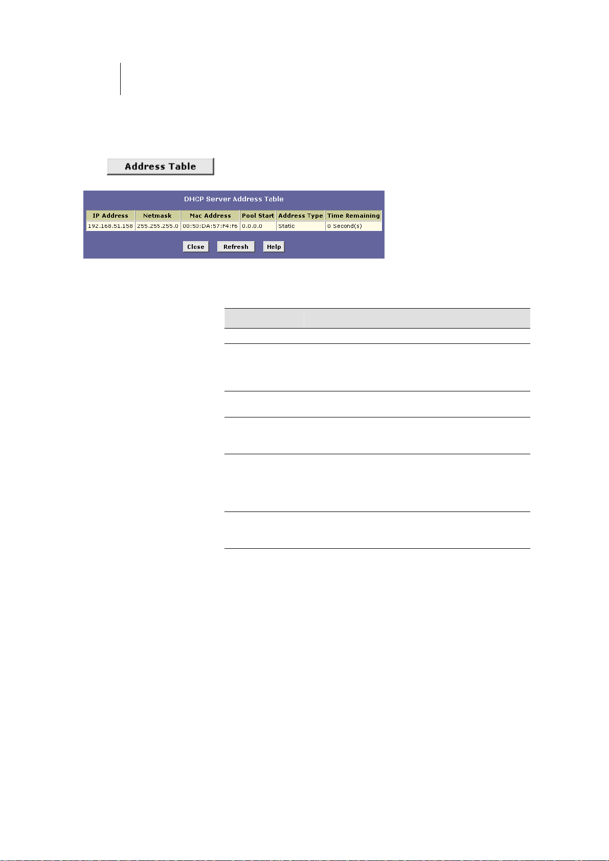
58
ATL Telecom User Guide
AM30
Viewing current DHCP address assignments
When the ROUTER functions as a DHCP server for your LAN, it keeps a record of any
addresses currently leased to your computers. To view a table of all current IP address
assignments, display the DHCP Server Configuration page, and then
click
.
A page displays similar to that shown in Figure 25:
Figure 25. DHCP Server Address Table Page
The DHCP Server Address Table lists any IP addresses that are currently leased to LAN
devices. For each leased address, the table lists the following information:
Field Description
IP Address
Netmask
Mac Address
Pool Start
Address Type Can be Static or Dynamic. Static indicates that the IP
Time Remaining
The address that has been leased from the pool.
The network mask associated with the leased address.
This identifies the network ID and host ID portions of
the address (see Appendix A for an explanation of
these terms).
The unique hardware ID of the computer to which the
IP address has been assigned.
The lower boundary of the address pool (shown here
to identify the pool from which the leased address was
assigned).
number has been assigned permanently to the specific
hardware device. Dynamic indicates that the number
has been leased temporarily for a specified length of
time.
The amount of time left for the device to use the
assigned address. The default lease time is 30day
(31536000 seconds).
Page 59
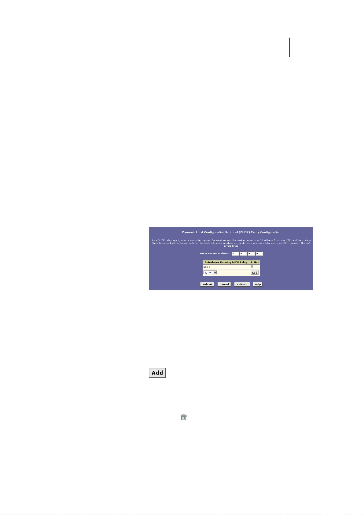
ATL Telecom User Guide
AM30
5
9
Configuring DHCP Relay
Some ISPs perform the DHCP server function for their customers’ home/small office
networks. In this case, you can configure the device as a DHCP relay agent. When a
computer on your network requests Internet access, the ROUTER contacts your ISP to
obtain an IP address (and other information), and then forwards that information to the
computer. Follow these instructions to configure DHCP relay:
First, you must configure your PCs to accept DHCP information assigned by a DHCP server:
1. Open the Windows Control Panel and display the computer's
Networking properties. Configure the TCP/IP properties to
"Obtain an IP address automatically" (the actual text may
vary depending on your operating system). For detailed
instructions, see the Quick Start chapter, “Part 2 —
Configuring Your Computers.”
Next, you specify the IP address of the DHCP server and select the interfaces on your
network that will be using the relay service.
2. Log into the Configuration Manager, click the LAN tab, and
then click DHCP Relay in the task bar.
The DHCP Relay Configuration page displays:
Figure 26. DHCP Relay Configuration Page
3. In the DHCP Server Address fields, type the IP address of
your ISP’s DHCP server.
If you do not have this number, it is not essential to enter
it here. Requests for IP information from your LAN will be
passed to the default gateway, which should route the
request appropriately.
4. Select your WAN interface from the drop-down list and click
.
Your WAN interface may be named ppp-0, eoa-0, or
ipoa-0. Contact your ISP if you are unsure which type of
WAN interface you use.
(Note that you can also delete an interface from the table
by clicking
in the right column.)
Page 60
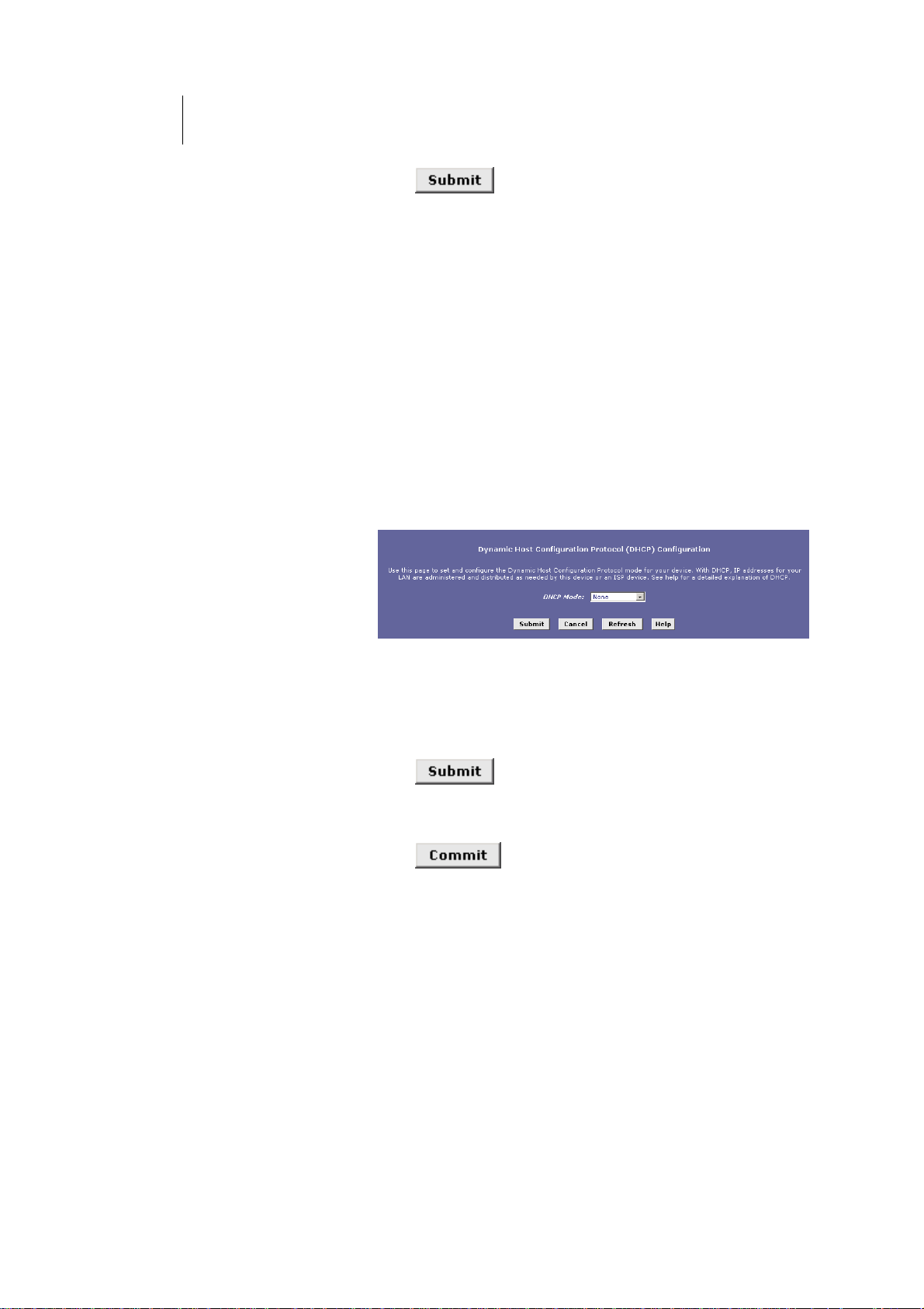
60
ATL Telecom User Guide
AM30
5. Click .
A page displays to confirm your changes, and then the
program returns to the DHCP Relay Configuration page.
6. Follow the instructions in “Setting the DHCP Mode” to set the
DHCP mode to DHCP Relay.
Setting the DHCP Mode
You must enable the appropriate DHCP mode to activate your DHCP relay or DHCP server
settings.
Follow these instructions to set the DHCP mode:
1. Click the LAN tab, and then click DHCP Mode in the task
bar.
The DHCP Configuration page displays, as shown in
Figure 27.
Figure 27. DHCP Configuration Page
2. From the DHCP Mode drop-down list, choose DHCP Server,
DHCP Relay, or None.
If you choose none, your LAN computers must be
configured with static IP addresses.
3. Click .
4. Click the Admin tab, and then click Commit & Reboot in
the task bar.
5. Click
memory.
to save your changes to permanent
Page 61
ATL Telecom User Guide
AM30
6
1
Configuring Network Address Translation
This chapter provides an overview of Network Address Translation (NAT) and instructions
for modifying the default configuration on your device.
Overview of NAT
Network Address Translation is a method for disguising the private IP addresses you use on
your LAN as the public IP address you use on the Internet. You define NAT rules that specify
exactly how and when to translate between public and private IP addresses.
A private IP address is created by a network administrator
for use only on a LAN, whereas a public IP address is
purchased from the Internet Corporation for Assigned
Definitions
Names and Numbers (ICANN) for use on the Internet.
Typically, your ISP provides a public IP address for your entire
LAN, and you define the private addresses for computers on
your LAN.
In a typical NAT setup, your ISP provides you with a single public IP address to use for your
entire network. Then, you assign each computer on your LAN a unique private IP address.
(Or, you define a pool of private IP addresses for dynamic assignment to your computers, as
described in Chapter 0.) On the ROUTER you set up a NAT rule to specify that whenever
one of your computers communicates with the Internet, (that is, it sends and receives IP
data packets) its private IP address—which is referenced in each packet—will be replaced by
the LAN’s public IP address.
An IP data packet contains bits of data bundled together in
a specific format for efficient transmission over the Internet.
Such packets are the building blocks of all Internet
communication. Each packet contains header information
that identifies the IP address of the computer that initiates
Definitions
the communication (the source IP address), the port
number that the router associates with that computer (the
source port number), the IP address of the targeted
Internet computer (the destination IP address), and other
information.
When this type of NAT rule is applied, because the source IP address is swapped out, it
appears to other Internet computers as if the data packets are actually originating from the
computer assigned your public IP address (in this case, the ROUTER ).
Page 62

62
ATL Telecom User Guide
AM30
The NAT rule could further be defined to disguise the source port in the data packet (i.e.,
change it to another number), so that outside computers will not be able to determine the
actual port from which the packet originated. Data packets that arrive in response contain
the public IP address as the destination IP address and the disguised source port number.
The ROUTER changes the IP address and source port number back to the original values
(having kept track of the changes it made earlier), and then routes the packet to the
originating computer.
NAT rules such as these provide several benefits:
fThey eliminate the need for purchasing multiple
public IP addresses for computers on your LAN. You
can make up your own private IP addresses at no
cost, and then have them translated to the public IP
address when your computers access the Internet.
fThey provide a measure of security for you LAN by
enabling you to assign private IP addresses and then
have these and the source port numbers swapped
out before your computers access the Internet.
The type of NAT function described above is called network address port translation (
NAPT).
You can use other types, called flavors, of NAT for other purposes; for example, providing
outside access to your LAN or translating multiple private addresses to multiple public
addresses.
For a description of
NAPT rules, see page 68.
Page 63
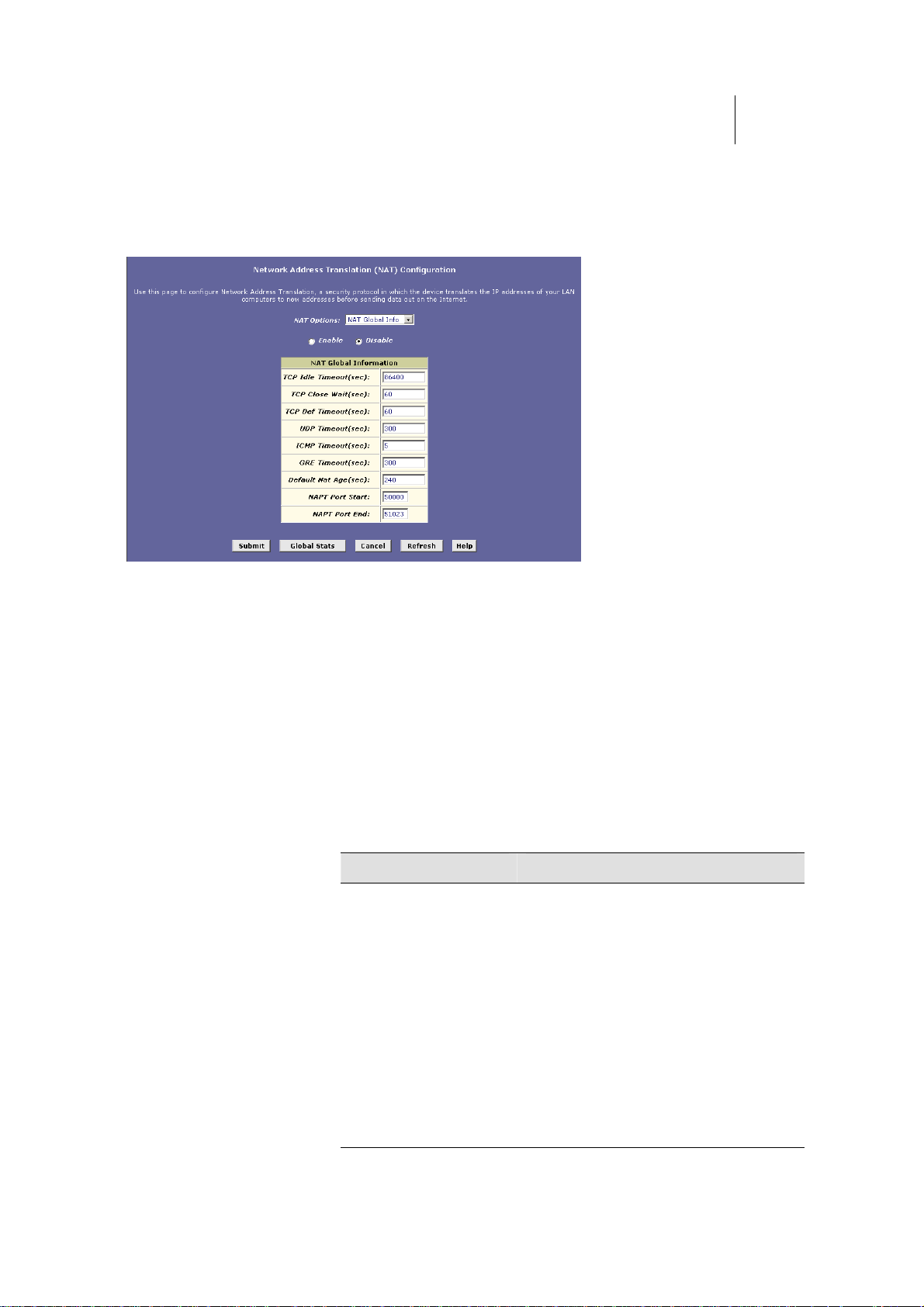
ATL Telecom User Guide
p
AM30
6
3
Viewing NAT Global Settings and Statistics
To view your NAT settings, log into Configuration Manager, click the Services tab. The NAT
Configuration page displays by default, as shown in Figure 28.
Figure 28. NAT Configuration Page
The NAT Configuration page contains the following elements:
he NAT Options drofT p-down list, which provides
access to the NAT Configuration page and Global
Information table (shown by default and in Figure
28), the NAT Rule Configuration page (see Figure
30), and the NAT Translations page (see Figure 32).
fEnable/Disable radio buttons, which allow you to turn
on or off the NAT feature.
fThe NAT Global Information table, which displays the
following settings that apply to all NAT rule
translations:
Field Description
TCP Idle Timeout (sec)
TCP Close Wait (sec)
TCP Def Timeout (sec)
When two computers communicate via the
Internet, a TCP-based communication session
is created between them to control the
exchange of data packets. The TCP session
can be in viewed as being in one of three
states, depending on the types of packets
being transferred: the establishing state,
where the connection is being set up, the
active state, where the connection is being
used to transfer data, and the closing state,
in which the connection is being shut down.
When a NAT rule is in effect on a TCP session
in the active state, the session will timeout if
no packets are received for the time specified
in TCP Idle Timeout. When in the closing
state, the session will timeout if no
ackets
Page 64
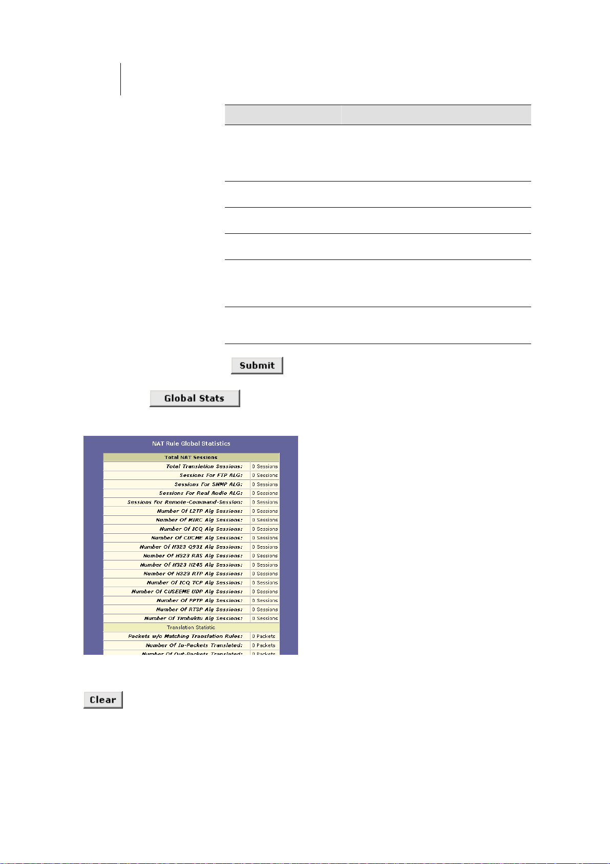
64
ATL Telecom User Guide
AM30
Field Description
are received for the time specified in TCP
Close Wait. When in the establishing state
the session will timeout if no packets are
received for the time specified in TCP Def
Timeout.
UDP Timeout (sec)
ICMP Timeout (sec)
GRE Timeout (sec)
Default Nat Age (sec)
NAPT Port Start/End
based communication sessions.
based communication sessions.
communication sessions.
For all other NAT translatio
number of seconds after which a translatio
session will no longer be valid if no packets
are received.
ports will be translated to sequential
numbers in this range.
CP Idle Timeout, but for UDP-Same as T
,
r ICMP-Same as TCP Idle Timeout, but fo
r GRE-basedSame as TCP Idle Timeout, but fo
n sessions, the
n
T rule is defined, the source When an NAP
If you change any values, click , and then click the Admin tab and commit your
emory (schanges to permanent system m ee page 40).
You can click
to view accumulated data on how many NAT rules have
been invoked and how much data has been translated. A page displays similar to the one
shown in Figure 29.
Figure 29. NAT Rule Global Statistics Page
The table provides basic information for each NAT rule you have set up. You can click
to restart the accumulation of the statistics at their initial values.
Page 65
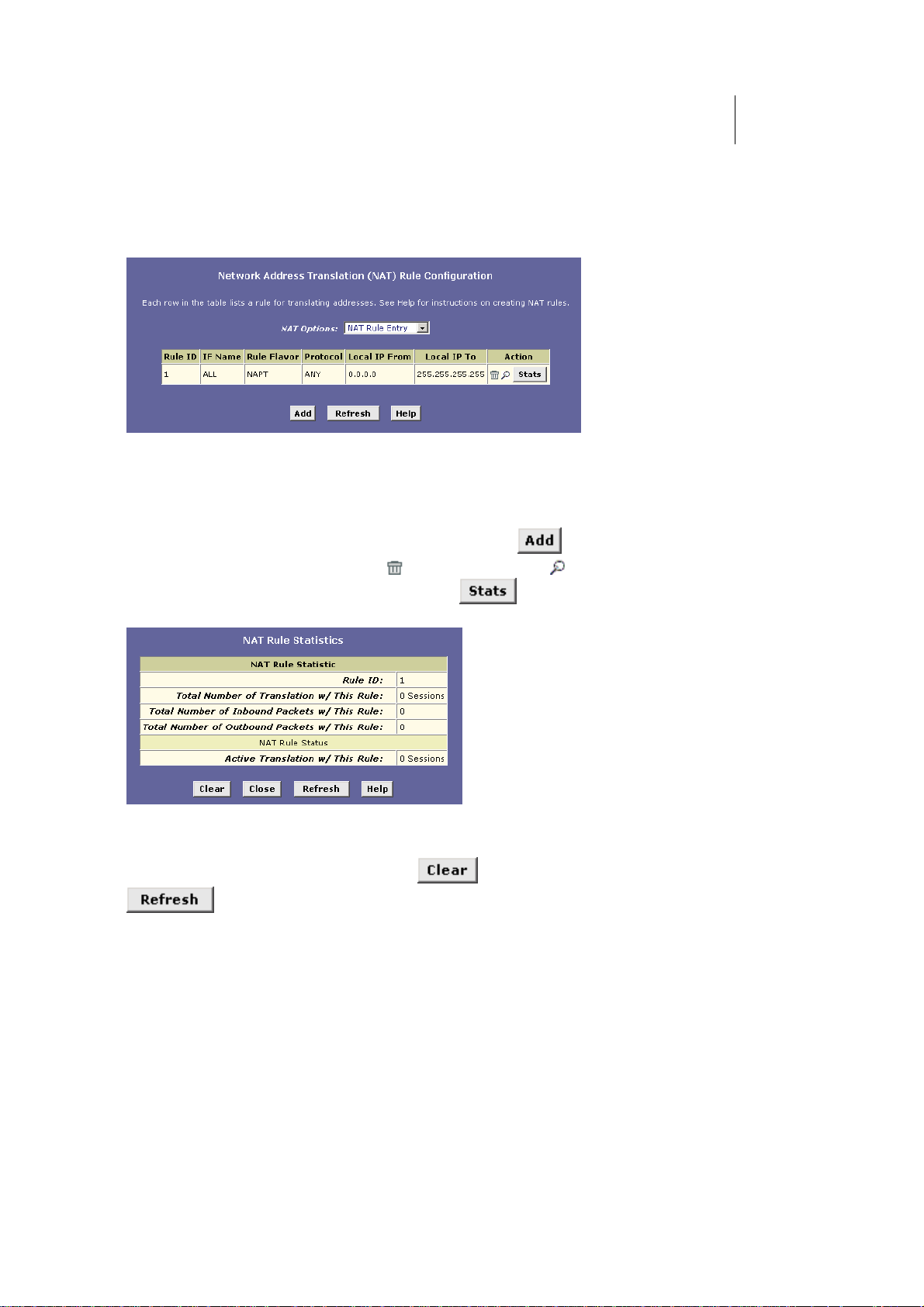
ATL Telecom User Guide
AM30
6
5
Viewing NAT Rules and Rule Statistics
To view the NAT rules currently defined on your system, select NAT Rule Entry in the NAT
Options drop-down list. The NAT Rule Configuration page displays, as shown in Figure 30.
Figure 30. NAT Rule Configuration Page
The NAT Rule Configuration table displays a row containing basic information for each rule.
For a description of these fields, refer to the instructions for adding rules (pages 68 through
77).
From the NAT Rule Configuration page, you can click
icons in the right column to delete (
) or view details on ( ) a rule. To view data on how
often a specific NAT rule has been used, click
to add a new rule, or use the
in the Action(s) column. A page
displays similar to the one shown in Figure 31:
Figure 31. NAT Rule Statistics Page
The statistics show how many times this rule has been invoked and how many currently active
sessions are using this rule. You can click
to display newly accumulated data.
to reset the statistics to zeros and
Page 66
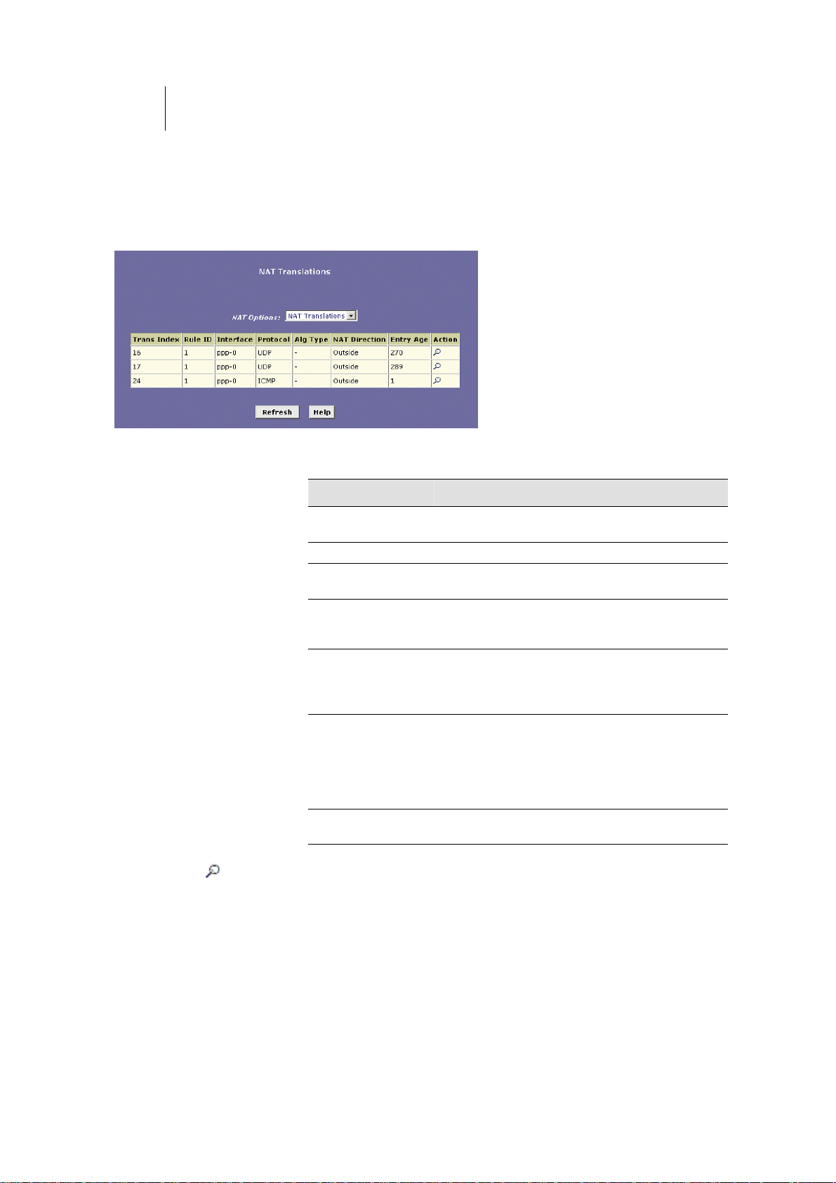
66
ATL Telecom User Guide
AM30
Viewing Current NAT Translations
To view a list of NAT translations that have recently been performed and which remain in
effect (for any of the defined rules), select NAT Translations from the NAT Options dropdown list. The NAT Translations page displays, as shown in Figure 32:
Figure 32. NAT Translations Page
For each current NAT translation session, the table contains the following fields:
Field Description
Trans Index
Rule ID
Interface
Protocol
Alg Type The Application Level Gateway (ALG), if any, that
NAT Direction
Entry Age
The sequential number assigne d to the IP session
used by this NAT translation session.
The ID of the NAT rule invoked.
The device interface on which the NAT rule was
invoked (from the rule definition).
The IP protocol used by the data packets that are
undergoing translations (from the rule definition)
Example: TCP, UDP, ICMP.
was used to enable this NAT translation (ALGs are
special settings that certain applications require in
order to work while NAT is enabled).
The direction (inside or outside) of the translation.
A NAT direction is assigned to each port; the
Ethernet and USB ports are defined as inside ports,
and the WAN ports are defined as outside ports.
The NAT direction is determined by the interface on
which the rule is invoked.
The elapsed time, in seconds, of the NAT
translation session.
You can click
in the Action column to view additional details about a NAT translation
session, as shown in Figure 33.
Page 67
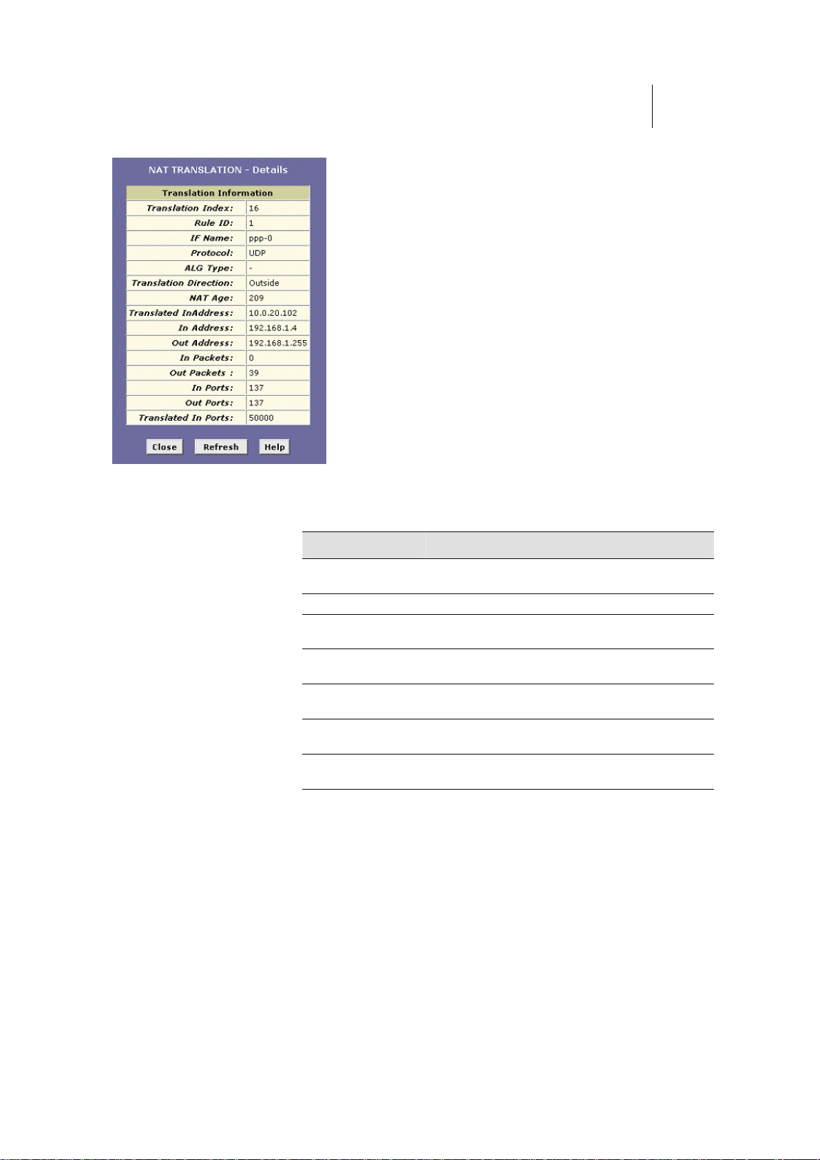
Figure 33. NAT Translation – Details Page
ATL Telecom User Guide
AM30
6
7
In addition to the information displayed in the NAT Translations table, this table displays the
following for the selected current translation sessions:
Field Description
Translated
InAddress
In Address
Out Address
In/Out Packets
In Ports
Out Ports
Translated In Ports
The public IP address to which the private IP
address was translated.
The private IP address that was translated.
The IP address of the outside destination (web, ftp
site, etc.)
The number of incoming and outgoing IP packets
that have been translated in this translation session.
The actual port number corresponding to the LAN
computer.
The port number associated with the destination
address.
The port number to which the LAN computer’s
actual port number was translated.
Page 68
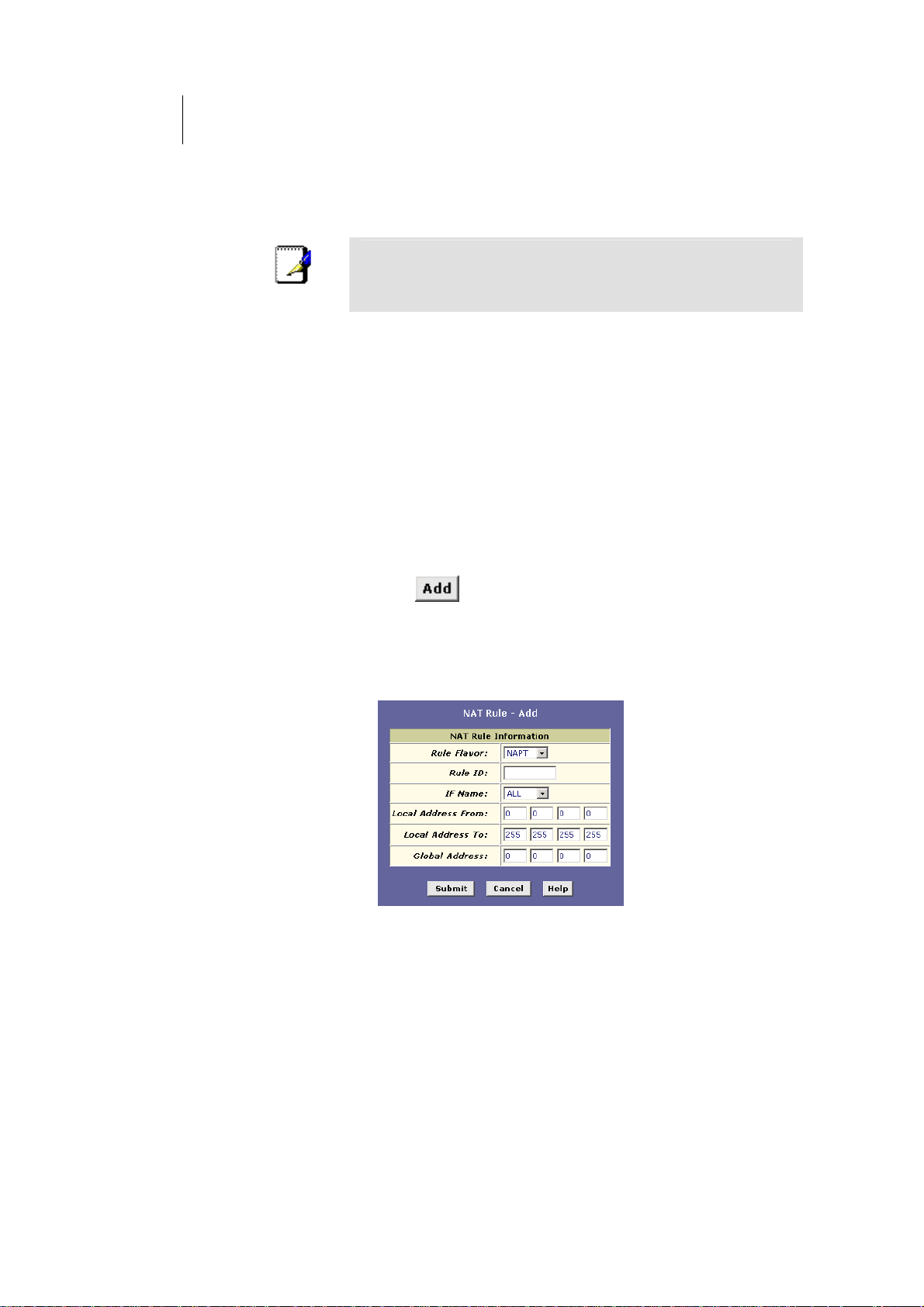
68
ATL Telecom User Guide
AM30
Adding NAT Rules
This section explains how to create rules for each NAT flavor.
You cannot edit existing NAT rules. To change a rule
setup, delete it and add a new rule with the modified
Note
settings.
The NAPT rule: Translating between private and public IP addresses
Follow these instructions to create a rule for translating the private IP addresses on your
LAN to your public IP address. This type of rule uses the NAT flavor
your default configuration. The
public IP address. The
NAPT rule also translates the source port numbers to port numbers
NAPT flavor translates private source IP addresses to a single
that are defined on the NAT Global Configuration page (see page 63). The Introduction to
NAT on page 61 describes how the
NAPT rule works.
1. Click the NAT tab, and then select NAT Rule Entry from the
NAT Options drop-down list.
The NAT Rule entry page displays a row for each
currently configured NAT rule.
NAPT, which was used in
2. Click to display the NAT Rule – Add page.
3. From the Rule Flavor drop-down list, select NAPT.
The page redisplays with only those fields that are
appropriate for the NAPT rule flavor, as shown in Figure
34.
Figure 34. NAT Rule – Add Page (NAPT Flavor)
Page 69

ATL Telecom User Guide
AM30
4. Enter a Rule ID.
6
9
The Rule ID determines the order in which rules are
invoked (the lowest numbered rule is invoked first, and
so on). If you define two or more rules that act on the
same set of IP addresses, be sure to assign the Rule ID so
that the higher priority rules are invoked first. It is
recommended that you specify rule IDs as multiples of 5
or 10 so that, in the future, you can insert a rule
between two existing rules.
Once a data packet matches a rule, the data is acted
upon according to that rule and is not subjected to
higher-numbered rules.
5. From the IFName drop-down list, select the interface on the
device to which this rule applies.
Typically, NAT rules are used for communication between
your LAN and the Internet. Because the device uses the
WAN interface (which may be named ppp-0, eoa-0, or
ipoa-0) to connect your LAN to your ISP, it is the usual
IFName selection.
6. In the Local Address From field and Local Address To fields,
type the starting and ending IP addresses, respectively, of
the range of private address you use on your network that
you want to be translated.
You can specify that data from all LAN addresses should
be translated by typing 0 (zero) in each From field and
255 in each To field. Or, type the same address in both
fields if the rule only applies to one LAN computer.
7. In the Global Address From and Global Address To fields,
type the public IP address assigned to you by your ISP.
If you have multiple WAN interfaces, in both fields type
the IP address of the interface to which this rule applies.
This rule will not be enforced for data that arrives on
other WAN interfaces.
If you have multiple WAN interfaces and want the rule to
be enforced on a range of them, type the starting and
ending IP addresses of the range.
8. Click .
9. When a page displays to confirm your change, click
to return to the NAT Configuration page.
The new rule should display in the NAT Rule
Configuration table.
10. Ensure that the Enable radio button is selected, and then
click
.
Page 70

70
ATL Telecom User Guide
AM30
A page displays to confirm your changes.
11. Click the Admin tab, and then click Commit and Reboot in
the task bar.
12. Click
memory.
to save your changes to permanent
Page 71
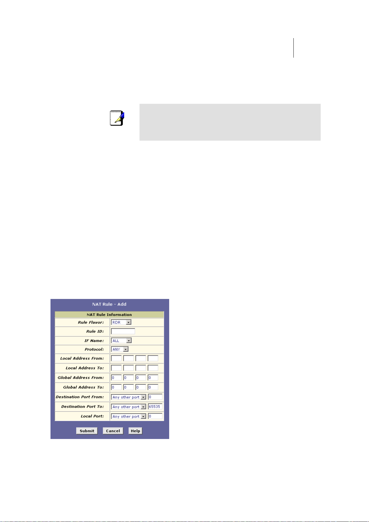
ATL Telecom User Guide
AM30
7
1
The RDR rule: Allowing external access to a LAN computer
You can create an RDR rule to make a computer on your LAN, such as a Web or FTP server,
available to Internet users without requiring you to obtain a public IP address for that
computer. The computer’s private IP address is translated to your public IP address in all
incoming and outgoing data packets.
Without an RDR rule (or Bimap rule described on page 77),
Note
The following example illustrates using the RDR rule to provide external access to your web
server:
the ROUTER blocks attempts by external computers to
access your LAN computers.
Your ADSL/Ethernet router receives a packet containing a
request for access to your Web server. The packet header
contains the public address for your LAN as the
destination IP address, and a destination port number of
80. Because you have set up an RDR rule for incoming
packets with destination port 80, the device recognizes
the data as a request for Web server access. The device
changes the packet's destination address to the private IP
address of your Web server and forwards the data packet
to it.
Your Web server sends data packets in response. Before
the ADSL/Ethernet router forwards them on to the
Internet, it changes the source IP address in the data
packets from the Web server's private address to your
LAN's public address. To an external Internet user then, it
appears as if your Web server uses your public IP address.
establish an RDR rule: Figure 35 shows the fields used to
Figure 35. NAT Rule – Add Page (RDR Flavor)
Page 72

72
ATL Telecom User Guide
AM30
Follow these instructions to add an RDR rule (see steps 1-4 under "The NAPT rule" on page
68 for specific instructions corresponding to steps 1 and 2 below):
1. Display the NAT Rule – Add Page, select RDR as the Rule
Flavor, if necessary, and enter a Rule ID.
2. Select the interface on which this rule will be effective.
3. Select a protocol to which this rule applies, or choose ANY.
This selection specifies which type of Internet
communication will be subject to this translation rule.
You can select ANY if the rule applies to all data. Or,
select TCP, UDP, ICMP, or a number from 1-255 that
represents the Internet Assigned Numbers Authority
(IANA)-specified protocol number.
4. In the Local Address From and Local Address To fields, type
the same private IP address, or the lowest and highest
addresses in a range:
fIf you type the same IP address in both fields,
incoming traffic that matches the criteria you specify
in steps 5 and 6 will be redirected to that IP address.
fIf you type a range of addresses, incoming traffic will
be redirected to any available computer in that
range. This option would typically be used for load
balancing, whereby traffic is distributed among
several redundant servers to help ensure efficient
network performance.
These addresses should correspond to private addresses
already in use on your network (either assigned statically
to your PCs or assigned dynamically using DHCP, as
discussed in the Quick Start, Part 2).
5. In the Global Address From and Global Address To fields,
type the public IP address assigned to you by your ISP.
If you have multiple WAN (PPP) interfaces, this rule will
not be enforced for data that arrives on other PPP
interfaces. This rule will not be enforced for data that
arrives on WAN interfaces not specified here.
If you have multiple WAN interfaces and want the rule to
be enforced on more than one of them (or all), type the
starting and ending IP addresses of the range.
6. From the Destination Port From and Destination Port To
drop-down lists, select the port type of the computer you are
making publicly available, or leave them set to Any other
port.
If you want to specify a port type that is not available in
the drop-down lists, you can instead type the port ID
number in text boxes to the right. You can specify a
range using the From/To fields if you want the rule to
Page 73

ATL Telecom User Guide
AM30
7
3
apply to a range of port types, or enter the same port
number in both fields.
If you leave the selection set to Any other port, then
incoming data will not be checked for the destination
port type.
A port ID identifies the specific function of the computer
connected to it, and therefore can limit the types of data
that pass to and from the computer. For example, Web
(HTTP) servers are usually identified by port number 80;
packets containing traffic destined for a Web server will
contain this port ID. The Internet Assigned Numbers
Authority (IANA) assigns port numbers for common types
of servers and functions.
7. If the LAN computer that you are making publicly available is
configured to use a non-standard port number for the type of
traffic it receives, type the non-standard port number in the
Local Port field.
This option translates the standard port number in
packets destined for your LAN computer to the nonstandard number you specify. For example, if your Web
server uses (non-standard) port 2000, but you expect
incoming data packets to refer to (standard) port 80, you
would enter 2000 here (and select HTTP or type 80 in the
Destination Port fields). The headers of incoming packets
destined for port 80 will be modified to refer to port
2000. The packet will then be routed appropriately to
the web server.
8. Follow steps 8-12 under "The NAPT rule" on page 68 to
submit your changes.
Page 74
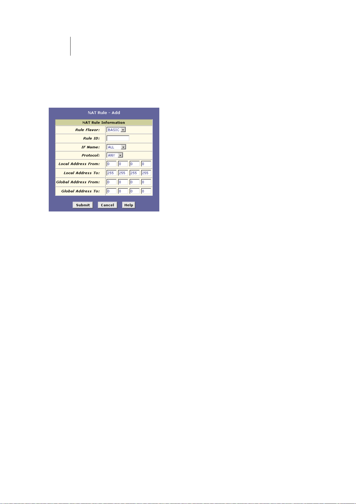
74
ATL Telecom User Guide
AM30
The Basic rule: Performing 1:1 translations
The Basic flavor translates the private (LAN-side) IP address to a public (WAN-side) address,
like NAPT rules. However, unlike NAPT rules, Basic rules do not also translate the port
numbers in the packet header; they are passed through untranslated. Therefore, the Basic
rule does not provide the same level of security as the NAPT rule.
Figure 36 shows the fields used for adding a Basic rule.
Figure 36. NAT Rule – Add Page (Basic Flavor)
Follow these instructions to add an BASIC rule (see steps 1-4 under "The NAPT rule" on
page 68 for specific instructions corresponding to steps 1 and 2 below):
1. Display the NAT Rule – Add Page, select BASIC as the Rule
Flavor, and enter a Rule ID.
2. Select the interface on which this rule will be effective.
3. Select a protocol to which this rule applies, or choose ANY.
This selection specifies which type of Internet
communication will be subject to this translation rule.
You can select ALL if the rule applies to all data. Or,
select TCP, UDP, ICMP, or a number from 1-255 that
represents the Internet Assigned Numbers Authority
(IANA)-specified protocol number.
4. In the Local Address From and Local Address To fields, type
the starting and ending IP addresses that identify the range
of private address you want to be translated. Or, type the
same address in both fields.
If you specify a range, each address will be translated in
sequence to a corresponding address in a range of global
addresses (which you specify in step 5).
You can create a BASIC rule for each specific address
translation to occur. The range of addresses should
correspond to private addresses already in use on your
network, whether assigned statically to your PCs, or
assigned dynamically using DHCP.
5. In the Global Address From and Global Address To fields,
type the starting and ending address that identify the pool of
Page 75
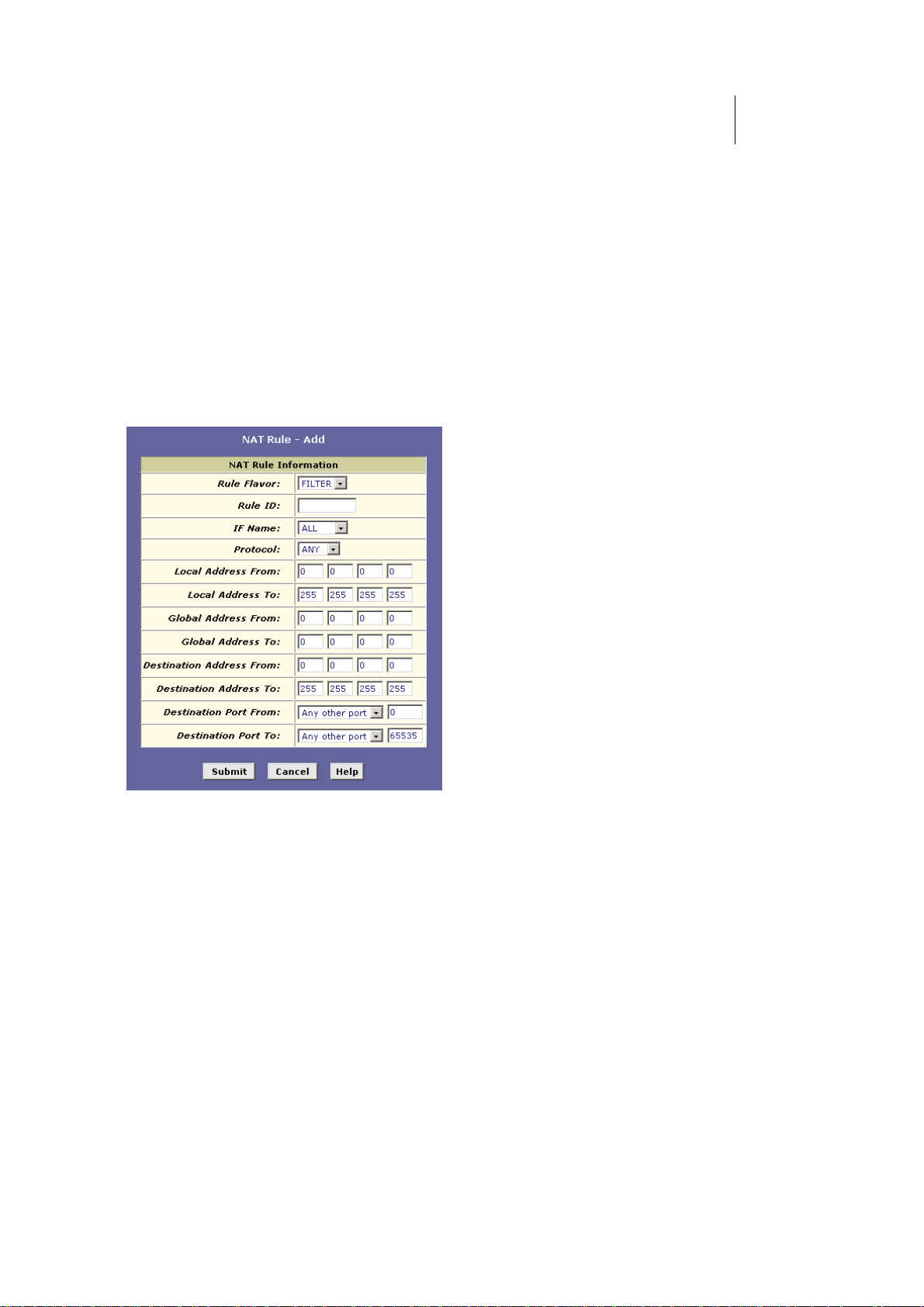
ATL Telecom User Guide
AM30
public IP addresses that the private addresses should be
translated to. Or, type the same address in both fields (if you
also specified a single address in step 4).
6. Follow steps 8-12 under "The NAPT rule" on page 68 to
submit your changes.
7
5
The Filter rule: Configuring a BASIC rule with additional criteria
Like the BASIC flavor, the Filter flavor translates public and private IP addresses on a one-toone basis. The Filter flavor extends the capability of the BASIC rule. Refer to “The BASIC
Rule” on page 74 for a general description.
You can use the Filter rule if you want an address translation to occur only when your LAN
computers initiate access to specific destinations. The destinations can be identified by their
IP addresses, port type (which identifies it as a FTP or Web server, for example), or both.
Figure 37 shows the fields used to establish a Filter rule.
Figure 37. NAT RuleAdd Page (Filter Flavor)
Follow these instructions to add a Filter rule (see steps 1-4 under "The NAPT rule" on page
68 for specific instructions corresponding to steps 1 and 2 below):
1. Display the NAT Rule – Add Page, select FILTER as the
Rule Flavor, and enter a Rule ID.
2. Select the interface on which this rule will be effective.
3. Select a protocol to which this rule applies, or choose ANY.
This selection specifies which type of Internet
communication will be subject to this translation rule.
You can select ANY if the rule applies to all data. Or,
select TCP, UDP, ICMP, or a number from 1-255 that
represents the Internet Assigned Numbers Authority
(IANA)-specified protocol number.
4. In the Local Address From and Local Address To fields, type
the starting and ending IP addresses that identify the range
Page 76

76
ATL Telecom User Guide
AM30
of private address you want to be translated. Or, type the
same address in both fields.
If you specify a range, each address will be translated in
sequence to a corresponding address in a range of global
addresses (which you specify in step 5).
The address (or range of addresses) should correspond to
a private addresses (or addresses) already in use on your
network. These may be assigned statically to your PCs or
assigned dynamically using DHCP, as discussed in the
Quick Start.
5. In the Global Address From and Global Address To fields,
type the starting and ending address that identify the range
of public IP addresses to translate your private addresses to.
Or, type the same address in both fields (if you also
specified a single address in step 4).
6. In the Destination Address From/To fields, specify a
destination address (or range) if you want this rule to apply
only to outbound traffic to the address (or range).
If you enter only the network ID portion of the
destination address, then the rule will apply to outbound
traffic to all computers on network.
7. From the Destination Port From/To drop-down lists, select a
port type if you want the rule to apply only to outbound traffic
to servers of this type. Otherwise, leave them set to Any
other port.
If you want to specify a port type that is not available in
the drop-down lists, you can instead type the port ID
number in text boxes to the right. You can specify a
range using the From/To fields if you want the rule to
apply to a range of port types, or enter the same port
number in both fields.
If you leave the selection set to Any other port, then
outbound data will not be checked for the destination
port type.
See step 6 for creating an RDR rule on page 72 for an
explanation of port IDs.
8. Follow steps 8-12 under "The NAPT rule" on page 68 to
submit your changes.
Page 77
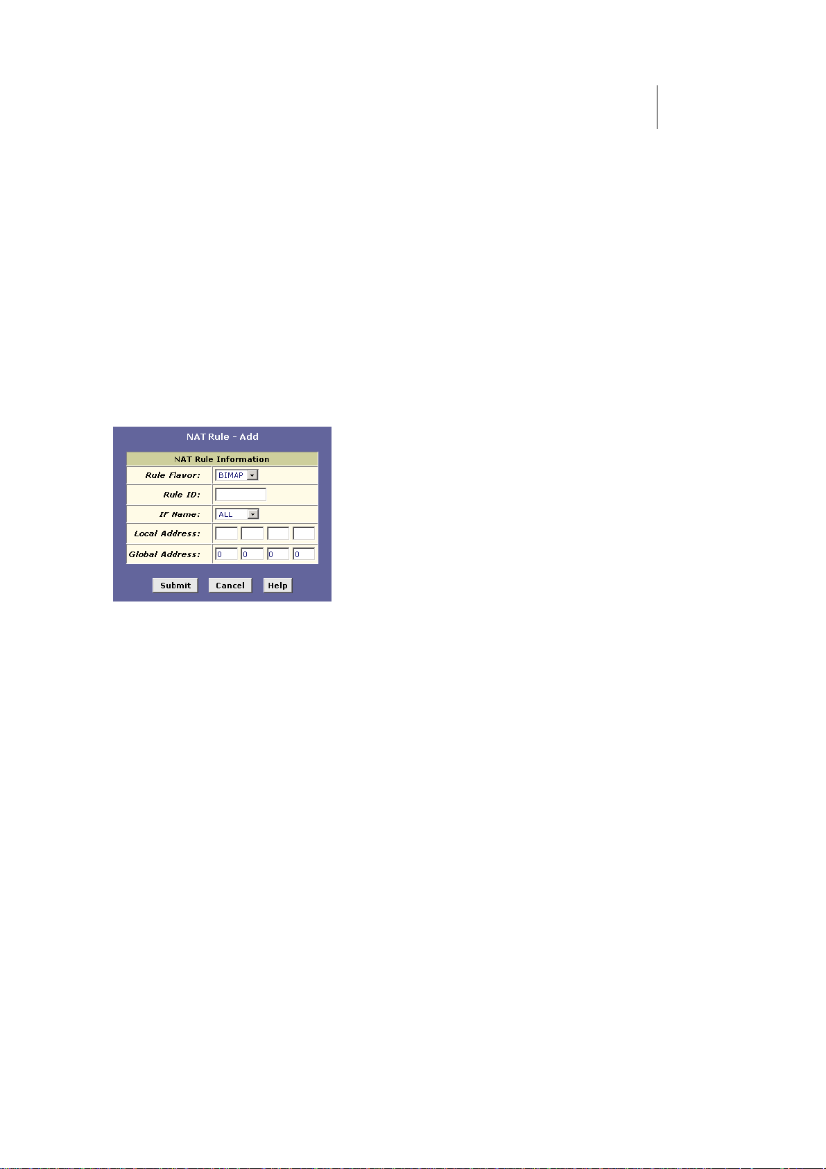
ATL Telecom User Guide
AM30
7
7
The Bimap rule: Performing two-way translations
Unlike the other NAT flavors, the Bimap flavor performs address translations in both the
outgoing and incoming directions.
In the incoming direction, when the specified ROUTER interface receives a packet with your
public IP address as the destination address, this address is translated to the private IP
address of a computer on your LAN. To the external computer, it appears as if the access is
being made to the public IP address, when, in fact, it is communicating with a LAN
computer.
In the outgoing direction, the private source IP address in a data packet is translated to the
LAN’s public IP address. To the rest of the Internet, it appears as if the data packet
originated from the public IP address.
Bimap rules can be used to provide external access to a LAN device. They do not provide
the same level of security as RDR rules, because RDR rules also reroute incoming packets
based on the port ID. Bimap rules do not account for the port number, and therefore allow
external access regardless of the destination port type specified in the incoming packet.
Figure 38 shows the fields used to establish a Bimap rule.
Figure 38. NAT Rule – Add Page (Bimap Flavor)
Follow these instructions to add a Bimap rule (see steps 1-4 under "The NAPT rule" on
page 68 for specific instructions corresponding to steps 1 and 2 below):
1. Display the NAT Rule – Add Page, select BIMAP as the
Rule Flavor, and enter a Rule ID.
2. Select the interface on which this rule will be effective.
3. In the Local Address field, type the private IP address of the
computer to which you are granting external access.
4. In the Global Address field, type the address that you want
to serve as the publicly known address for the LAN
computer.
5. Follow steps 8-12 under "The NAPT rule" on page 68 to
submit your changes.
The Pass rule: Allowing specific addresses to pass through untranslated
You can create a Pass rule to allow a range of IP addresses to remain untranslated when
another rule would otherwise do so.
Page 78
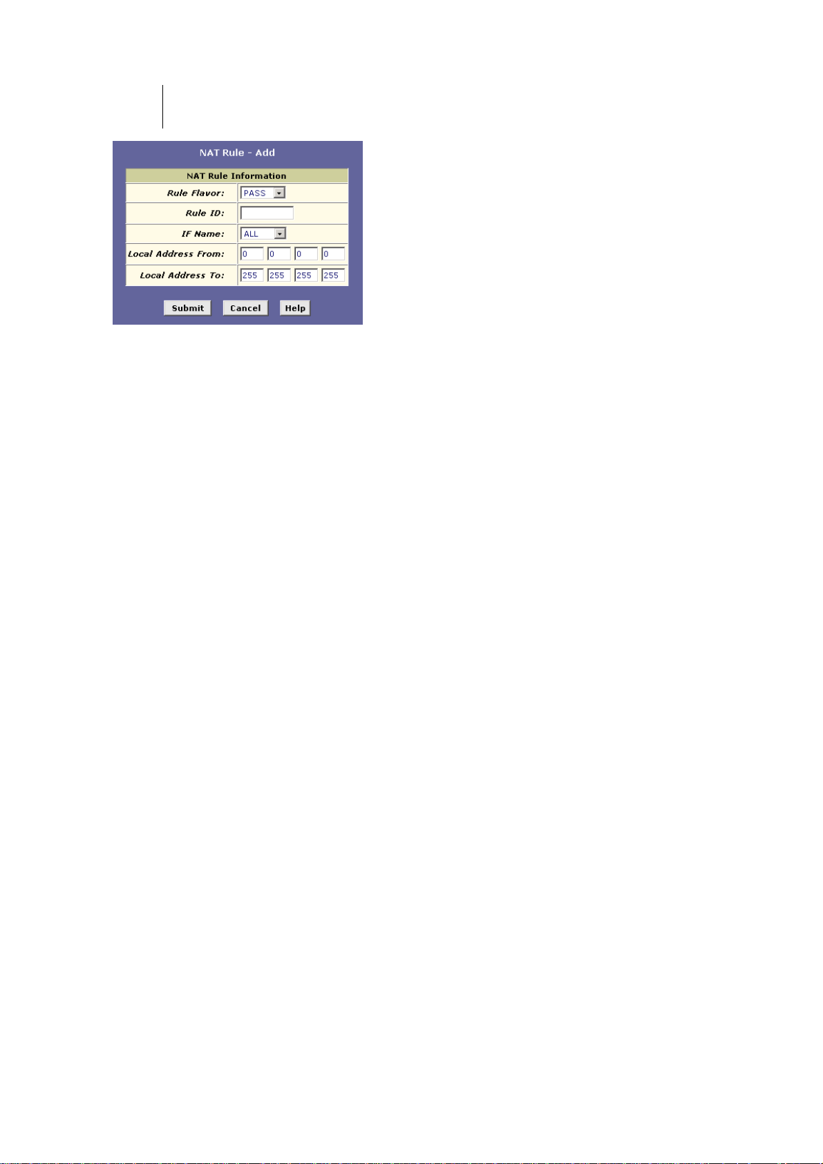
78
ATL Telecom User Guide
AM30
Figure 39. NAT Rule – Add Page (Pass Flavor)
The Pass rule must be assigned a rule ID that is a lower number than the ID assigned to the
rule it is intended to pass. In you want a specific IP address or range of addresses to not be
subject to an existing rule, say rule ID #5, then you can create a Pass rule with ID #1
through #4.
Follow these instructions to add a Pass rule (see steps 1-4 under "The NAPT rule" on page
68 for detailed instructions corresponding to steps 1 and 2 below):
1. Display the NAT Rule – Add Page, select PASS as the Rule
Flavor, and enter a Rule ID.
2. Select the interface on which this rule will be effective.
3. In the Local Address From and Local Address To fields, type
the lowest and highest IP addresses that define the range of
private address you want to be passed without translation.
If you want the Pass rule to act on only one address, type
that address in both fields.
4. Follow steps 7-12 under "The NAPT rule" on page 68 to
submit your changes.
Page 79
ATL Telecom User Guide
AM30
7
9
Configuring DNS Server Addresses
About DNS
Domain Name System (DNS) servers map the user-friendly domain names that users type
into their Web browsers (e.g., "yahoo.com") to the equivalent numerical IP addresses that
are used for Internet routing.
When a PC user types a domain name into a browser, the PC must first send a request to a
DNS server to obtain the equivalent IP address. The DNS server will attempt to look up the
domain name in its own database, and will communicate with higher-level DNS servers
when the name cannot be found locally. When the address is found, it is sent back to the
requesting PC and is referenced in IP packets for the remainder of the communication.
Assigning DNS Addresses
Multiple DNS addresses are useful to provide alternatives when one of the servers is down
or is encountering heavy traffic. ISPs typically provide primary and secondary DNS addresses,
and may provide additional addresses. Your LAN PCs learn these DNS addresses in one of
the following ways:
fStatically: If your ISP provides you with their DNS
server addresses, you can assign them to each PC by
modifying the PCs' IP properties.
fDynamically from a DHCP pool: You can configure
the DHCP Server feature on the ADSL/Ethernet router
and create an address pool that specifies the DNS
addresses to be distributed to the PCs. Refer to
Chapter 0, “Configuring DHCP Server” on page 53
for instructions on creating DHCP address pools.
In either case, you can specify the actual addresses of the ISP's DNS servers (on the PC or in
the DHCP pool), or you can specify the address of the LAN port on the ADSL/Ethernet
router (e.g., 192.168.1.1). When you specify the LAN port IP address, the device performs
DNS relay, as described in the following section.
Note
If you specify the actual DNS addresses on the PCs or in
the DHCP pool, the DNS relay feature is not used.
Page 80

80
ATL Telecom User Guide
AM30
Configuring DNS Relay
When you specify the ROUTER's LAN port IP address as the DNS address, then the device
automatically performs “DNS relay”; i.e., because the device itself is not a DNS server, it forwards
domain name lookup requests it receives from the LAN PCs to a DNS server at the ISP. It then
relays the DNS server’s response to the PC.
When performing DNS relay, the ROUTER must maintain the IP addresses of the DNS servers it
contacts. It can learn these addresses in either or both of the following ways:
fLearned through PPP: If the device uses a PPP
connection to the ISP, the primary and secondary
DNS addresses can be learned via the PPP protocol.
To use this method, the "Use DNS" checkbox must
be selected in the PPP interface properties. (See
Chapter 0 for instructions on configuring your PPP
interface. Note that you cannot change this property
by modifying an existing PPP interface; you must
delete the interface and recreate it with the new
setting.)
Using this option provides the advantage that you
will not need to reconfigure the PCs or the
ADSL/Ethernet router if the ISP changes their DNS
addresses.
fConfigured on the ADSL/Ethernet router: You
can use the device's DNS feature to specify the ISP's
DNS addresses. If the device also uses a PPP interface
with the "Use DNS" property enabled, then these
configured addresses will be used in addition to the
two addresses learned through PPP. If "Use DNS" is
not enabled, or if a protocol other than PPP is used
(such as EoA), then these configured addresses will
be used as the primary and secondary DNS
addresses.
Follow these steps to configure DNS relay:
1. Configure the LAN PCs to use the ADSL/Ethernet router's
LAN IP address as their DNS server address—by assigning
the LAN IP address statically to each PC, or by inputting the
LAN IP address or the address 0.0.0.0 as the DNS address
in the DHCP server pool used by the PCs.
2. If using a PPP connection to the ISP, click the "Use DNS"
check box so that the DNS server addresses it learns are
used for DNS relay.
Or, ...
If not using a PPP connection (or if you want to specify DNS
addresses in addition to those learned through PPP),
configure the DNS addresses on the ADSL/Ethernet router
Page 81

as follows:
ATL Telecom User Guide
AM30
8
1
Page 82
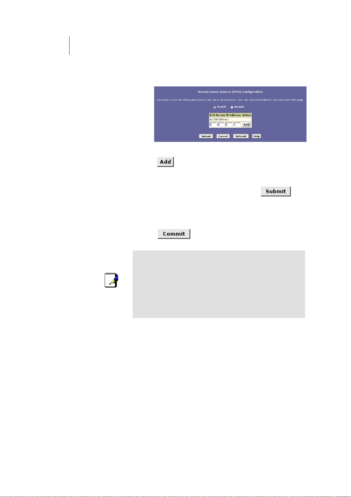
82
ATL Telecom User Guide
AM30
a.
Click the Services tab, and then click DNS in the task bar. The
DNS Configuration page displays.
Figure 40. DNS Configuration Page
b. Type the IP address of the DNS server in an empty row and click
.
You can enter only two addresses.
c.
Click the Enable radio button, and then click .
Note
3. Click the Admin tab, and then click Commit & Reboot in
the task bar.
4. Click
to save your changes to permanent
memory.
DNS addresses that are assigned to LAN PCs prior to
enabling DNS relay will remain in effect until the PC is
rebooted. DNS relay will only take effect when a PC's DNS
address is the LAN IP address.
Similarly, if after enabling DNS relay, you specify a DNS
address (other than the LAN IP address) in a DHCP pool or
statically on a PC, then that address will be used instead of
the DNS relay address.
Page 83

ATL Telecom User Guide
AM30
8
3
Configuring IP Routes
You can use Configuration Manager to define specific routes for your Internet and network
data. This chapter describes basic routing concepts and provides instructions for creating
routes.
Note that most users do not need to define IP routes.
Overview of IP Routes
The essential challenge of a router is: when it receives data intended for a particular
destination, which next device should it send that data to? When you define IP routes, you
provide the rules that a computer uses to make these decisions.
IP routing versus telephone switching
IP routing decisions are similar to those made by switchboards that handle telephone calls.
When you dial a long distance telephone number, you are first connected to a switchboard
operated by your local phone service carrier. All calls you initiate go first to this main
switchboard.
If the phone number you dialed is outside your calling area, the switchboard opens a
connection to a higher-level switchboard for long distance calls. That switchboard looks at
the area code you dialed and connects you with another switchboard that serves that area.
This new switchboard, in turn, may look at the prefix in the number you dialed (the middle
set of three numbers) and connect to a more localized switchboard that handles numbers
with that prefix. This final switchboard can then look at the last four digits of the phone
number to open a connection with the person or company you dialed.
In comparison, when your computer initiates communication over the Internet, such as
viewing a web page connecting to an web server, the data it sends out includes the IP
address of the destination computer (the “phone number”). All your outgoing requests first
go to the same router at your ISP (the first “switchboard”). That router looks at the
network ID portion of the destination address (the “area code”) and determines which next
router to send the request to. After several such passes, the request arrives at a router for
the destination network, which then uses the host ID portion of the destination IP address
(the local “phone number”) to route the request to the appropriate computer. (The
network ID and host ID portions of IP addresses are explained in Appendix 0.)
With both the telephone and the computer, all transactions are initially sent to the same
switchboard or router, which serves as a gateway to other higher- or lower-level devices.
No single device knows at the outset the eventual path the data will take, but each uses a
specific part of the destination address/phone number to make a decision about which
device to connect to next.
Page 84

84
ATL Telecom User Guide
AM30
Hops and gateways
Each time Internet data is passed from one Internet address to another, it is said to take a
hop. A hop can be a handoff to a different port on the same device, to a different device
on the same network, or to a device on an entirely different network.
When a hop passes data from one type of network to another, it uses a gateway. A
gateway is an IP address that provides initial access to a network, just as a switchboard
serves as a gateway to a specific set of phone numbers. For example, when a computer on
your LAN requests access to a company’s web site, your ISP serves as a gateway to the
Internet. As your request reaches its destination, another gateway provides access to the
company’s web servers.
Using IP routes to define default gateways
IP routes are defined on computers, routers, and other IP-enabled devices to instruct them
which hop to take, or which gateway to use, to help forward data along to its specified
destination.
If no IP route is defined for a destination, then IP data is passed to a predetermined default
gateway. The default gateway serves like a higher-level telephone switchboard; it may not
be able to connect directly to the destination, but it will know a set of other devices that
can help pass the data intelligently. If it cannot determine which of these devices provides a
good next hop (because no such route has been defined), then that device will forward the
data to its default gateway. Eventually, a high level device, using a predefined IP route, will
be able to forward the data along a path to its destination.
Do I need to define IP routes?
Most users do not need to define IP routes. On a typical small home or office LAN, the
existing routes that set up the default gateways for your LAN computers and for the
ROUTER provide the most appropriate path for all your Internet traffic.
fOn your LAN computers, a default gateway directs all
Internet traffic to the LAN port on the ROUTER. Your
LAN computers know their default gateway either
because you assigned it to them when you modified
their TCP/IP properties, or because you configured
them to receive the information dynamically from a
server whenever they access the Internet. (Each of
these processes is described in the Quick Start
instructions, Part 2.)
fOn the ROUTER itself, a default gateway is defined to
direct all outbound Internet traffic to a router at your
ISP. This default gateway is assigned automatically by
your ISP whenever the device negotiates an Internet
connection. (The process for adding a default route is
described on page 87.)
You may need to define routes if your home setup includes two or more networks or subnets, if
you connect to two or more ISP services, or if you connect to a remote corporate LAN.
Page 85
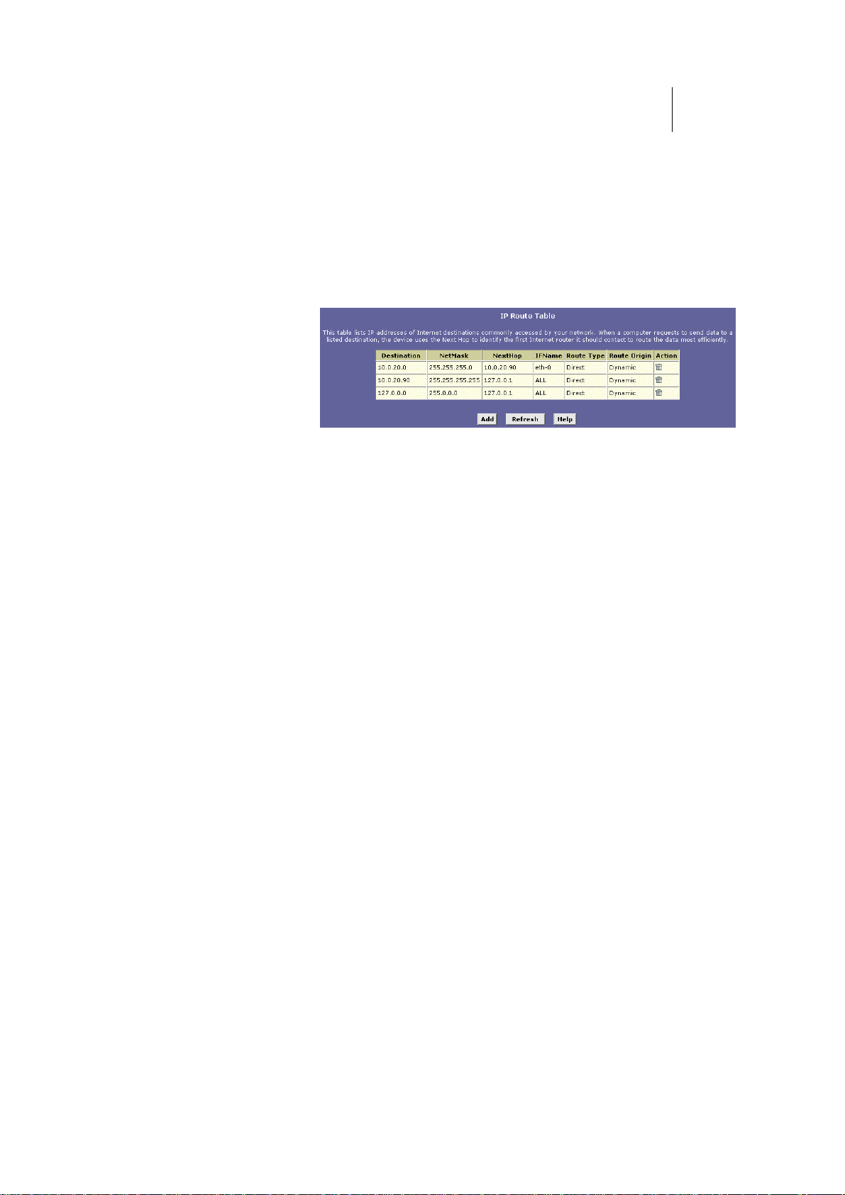
ATL Telecom User Guide
AM30
8
5
Viewing the IP Routing Table
All IP-enabled computers and routers maintain a table of IP addresses that are commonly
accessed by their users. For each of these destination IP addresses, the table lists the IP
address of the first hop the data should take. This table is known as the device’s routing
table.
To view the ROUTER’s routing table, click the Routing tab. The IP Route page displays by
default, as shown in Figure 41:
Figure 41. IP Route Table Page
The IP Route Table displays a row for each existing route.
These include routes that were predefined on the device,
routes you may have added, and routes that the device has
identified automatically through communication with other
devices.
The routing table should reflect a default gateway, which
directs outbound Internet traffic to your ISP. This default
gateway is shown in the row containing destination address
0.0.0.0.
Page 86

86
ATL Telecom User Guide
AM30
The following table defines the fields in the IP Routing Table.
Field Description
Destination
Netmask
NextHop Specifies the next IP address to send data to when its
IFName
Route Type
Route Origin Displays how the route was defined. Dynamic indicates
Action
Specifies the IP address of the destination computer.
The destination can specified as the IP address of a
specific computer or an entire network. It can also be
specified as all zeros to indicate that this route should
be used for all destinations for which no other route is
defined (this is the route that creates the default
gateway).
Indicates which parts of the destination address refer to
the network and which parts refer to a computer on
the network. Refer to Appendix 0, for an explanation of
network masks. The default gateway uses a netmask of
0.0.0.0.
final destination is that shown in the destination
column.
Displays the name of the interface on the device
through which data is forwarded to the specified next
hop.
Displays whether the route is direct or indirect. In a
direct route, the source and destination computers are
on the same network, and the router attempts to
directly deliver the data to the computer. In an indirect
route, the source and destination computers are on
different networks, and the router forwards data to a
device on another network for further handling.
that the route was created automatically or predefined
by your ISP or the manufacturer. Routes you create are
labeled Local. Other routes can be created
automatically (using RIP, as described in Chapter 0), or
defined remotely through various network
management protocols (LCL or ICMP).
Displays an icon (
) you can click on to delete a route.
Page 87
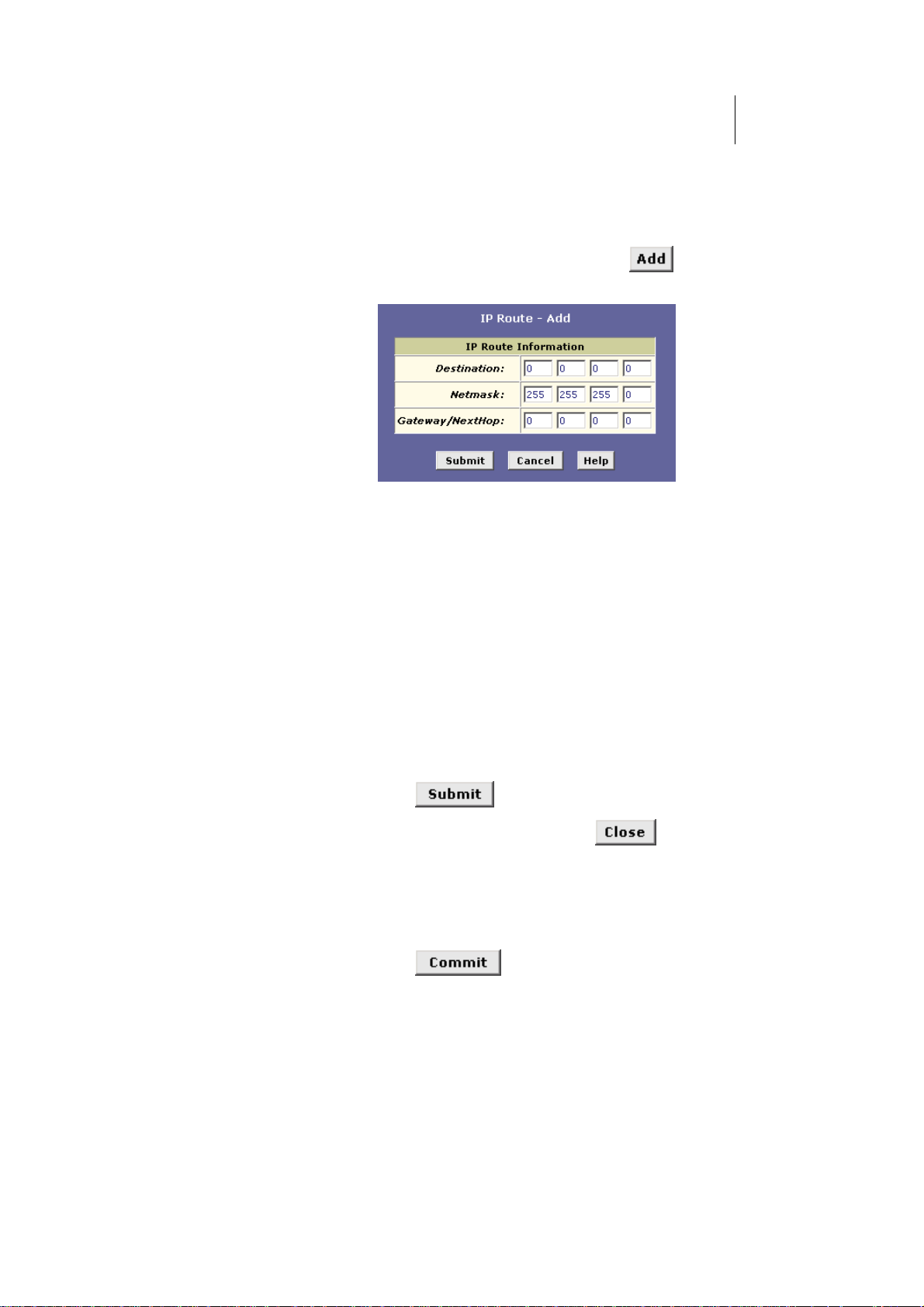
ATL Telecom User Guide
Adding IP Routes
Follow these instructions to add an IP route to the routing table.
1. From the IP Route Table page, click .
The IP Route – Add page displays, as shown in Figure 42.
Figure 42. IP Route – Add Page
2. network mask, and gateway or next hop for this route.
For a description of these fields, refer to the table on
page 86.
To create a route that defines the default gateway for
your LAN, enter 0.0.0.0 in both the Destination and Net
Mask fields. Enter your ISP’s IP address in the
Gateway/NextHop field.
Note that you cannot specify the interface name, route
type or route origin. These parameters are used only for
routes that are identified automatically as the device
communicates with other routing devices. For routes you
create, the routing table displays system default values in
these fields.
AM30
8
7
3. Click .
4. On the confirmation page, click
Route table page.
The IP Routing Table will now display the new route.
5. Click the Admin tab, and then click Commit & Reboot in the
task bar.
6. Click
memory.
to save your changes to permanent
to return to the IP
Page 88

Page 89

ATL Telecom User Guide
AM30
8
9
Configuring the Routing Information Protocol
The ROUTER can be configured to communicate with other routing devices to determine
the best path for sending data to its intended destination. Routing devices communicate
this information using a variety of IP protocols. This chapter describes how to configure the
ROUTER to use one of these, called the Routing Information Protocol (RIP).
RIP Overview
RIP is an Internet protocol you can set up to share routing table information with other
routing devices on your LAN, at your ISP’s location, or on remote networks connected to
your network via the ADSL line. Generally, RIP is used to enable communication on
autonomous networks. An autonomous network is one in which all of the computers are
administered by the same entity. An autonomous network may be a single network, or a
grouping of several networks under the same administration. An example of an
autonomous network is a corporate LAN, including devices that can access it from remote
locations, such as the computers telecommuters use.
Using RIP, each device sends its routing table to its closest neighbor every 30 seconds. The
neighboring device in turn passes the information on to its next neighbor and so on until all
devices in the autonomous network have the same set of routes.
When should you configure RIP?
Most small home or office networks do not need to use RIP; they have only one router,
such as the ROUTER, and one path to an ISP. In these cases, there is no need to share
routes, because all Internet data from the network is sent to the same ISP gateway.
You may want to configure RIP if any of the following circumstances apply to your network:
fYour home network setup includes an additional
router or RIP-enabled PC (other than the ROUTER).
The ROUTER and other router will need to
communicate via RIP to share their routing tables.
fYour network connects via the ADSL line to a remote
network, such as a corporate network. In order for
your LAN to learn the routes used within your
corporate network, they should both be configured
with RIP.
fYour ISP requests that you run RIP for communication
with devices on their network.
Page 90
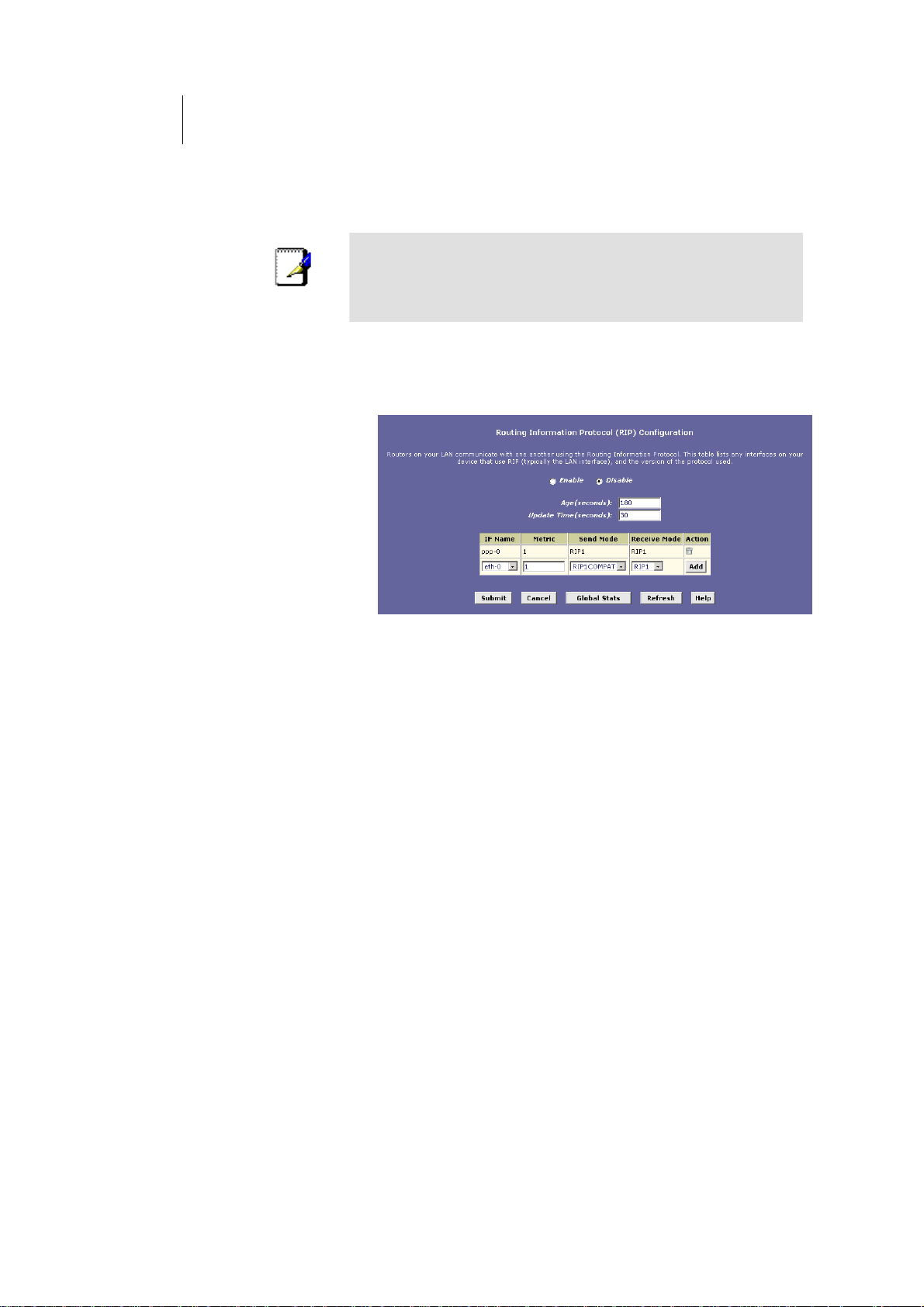
90
ATL Telecom User Guide
AM30
Configuring the ROUTER’s Interfaces with RIP
The following instructions describe how to enable RIP on the ROUTER .
In order for the ROUTER to communicate with other
devices using RIP, you must also enable the other devices
Note
to use the protocol. See the product documentation for
those devices.
1. Log into the Configuration Manager, click the Services tab,
and then click
RIP in the task bar.
The RIP Configuration page displays, as shown in Figure
43.
Figure 43. RIP Configuration Page
The page contains radio buttons for enabling or disabling
the RIP feature and a table listing interfaces on which the
protocol is currently running. The first time you open this
page, the table may be empty.
2. If necessary, change the Age and Update Time.
These are global settings for all interfaces that use RIP.
fAge is the amount of time in seconds that the
device’s RIP table will retain each route that it learns
from adjacent computers.
fUpdate Time specifies how frequently the ROUTER
will send out its routing table its neighbors.
3. In the IFName column, select the name of the interface on
which you want to enable RIP.
For communication with RIP-enabled devices on your
LAN, select eth-0 or the name of the appropriate virtual
Ethernet interface.
For communication with your ISP or a remote LAN, select
the corresponding ppp, eoa, or other WAN interface.
(See page 49 for a description of various interfaces and
their names.)
Page 91
ATL Telecom User Guide
AM30
4. Select a metric value for the interface.
RIP uses a “hop count” as a way to determine the best
path to a given destination in the network. The hop
count is the sum of the metric values assigned to each
port through which data is passed before reaching the
destination. Among several alternative routes, the one
with the lowest hop count is considered the fastest path.
For example, if you assign this port a metric of 1, then
RIP will add 1 to the hop count when calculating a route
that passes through this port. If you know that
communication via this interface is slower than through
other interfaces on your network, you can assign it a
higher metric value than the others.
You can select any integer from 1 to 15.
5. Select a Send Mode and a Receive Mode.
The Send Mode setting indicates the RIP version this
interface will use when it sends its route information to
other devices.
The Receive Mode setting indicates the RIP version(s) in
which information must be passed to the ROUTER in
order for it to be accepted into its routing table.
RIP version 1 is the original RIP protocol. Select RIP1 if
you have devices that communicate with this interface
that understand RIP version 1 only.
RIP version 2 is the preferred selection because it
supports “classless” IP addresses (which are used to
create subnets) and other features. Select RIP2 if all other
routing devices on the autonomous network support this
version of the protocol.
9
1
Note
6. Click .
The new RIP entry will display in the table.
7. Click the Enable radio button to enable the RIP feature.
If you disable the RIP feature, the interface settings you
have configured will remain available for future activation.
8. When you are finished defining RIP interfaces, click
.
A page displays to confirm your changes.
9. Click the Admin tab, and then click Commit & Reboot in the
task bar.
10. Click
memory.
to save your changes to permanent
Page 92

92
ATL Telecom User Guide
AM30
Note
You can delete an existing RIP entry by clicking in the
Action column.
Page 93
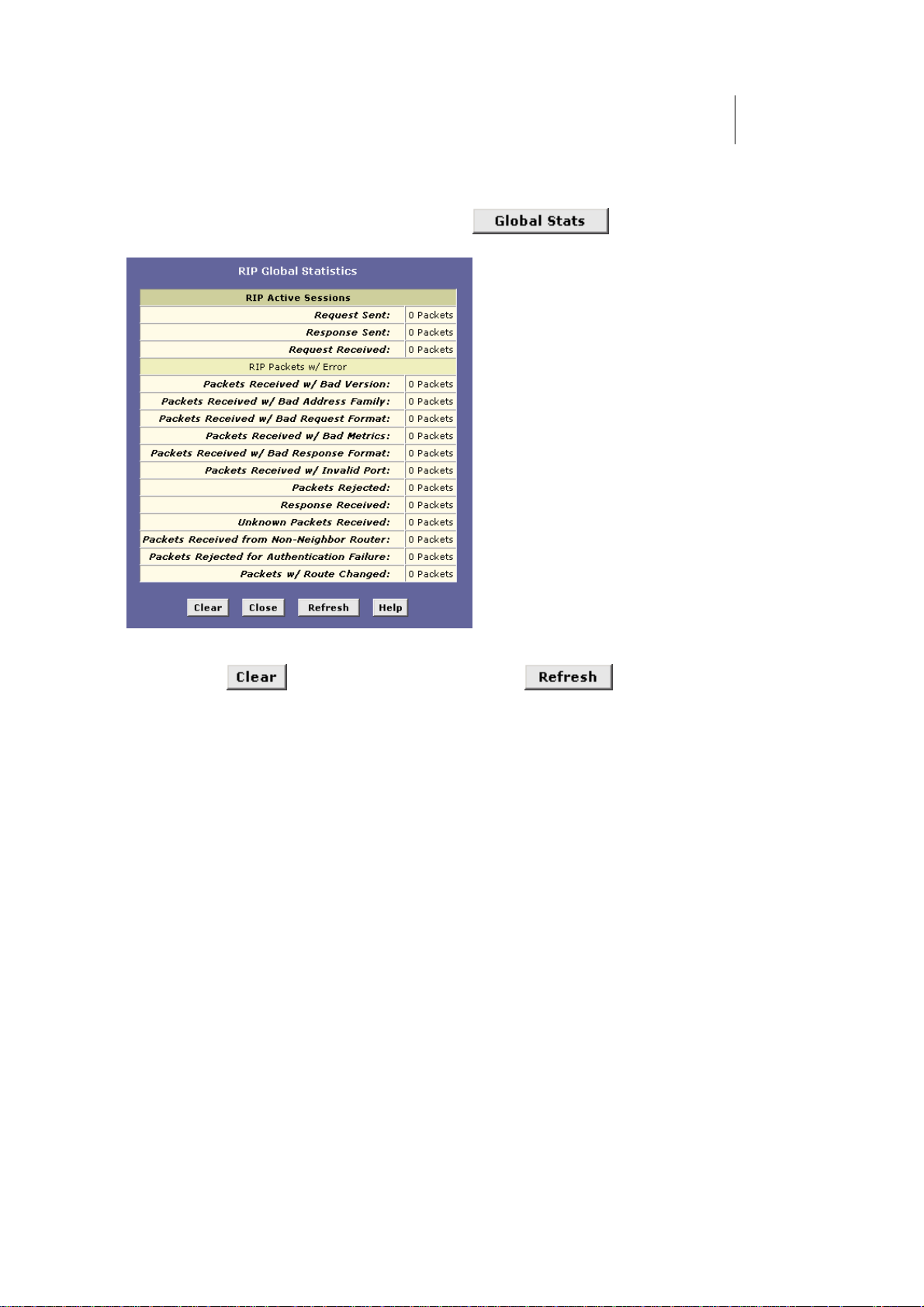
ATL Telecom User Guide
AM30
9
3
Viewing RIP Statistics
From the RIP Configuration page, you can click to view statistics on
attempts to send and receive route table data over RIP-enabled interfaces on the ROUTER
Figure 44. RIP Global Statistics Page
You can click to reset all statistics to zero and to display any newly
accumulated data.
Page 94

Page 95
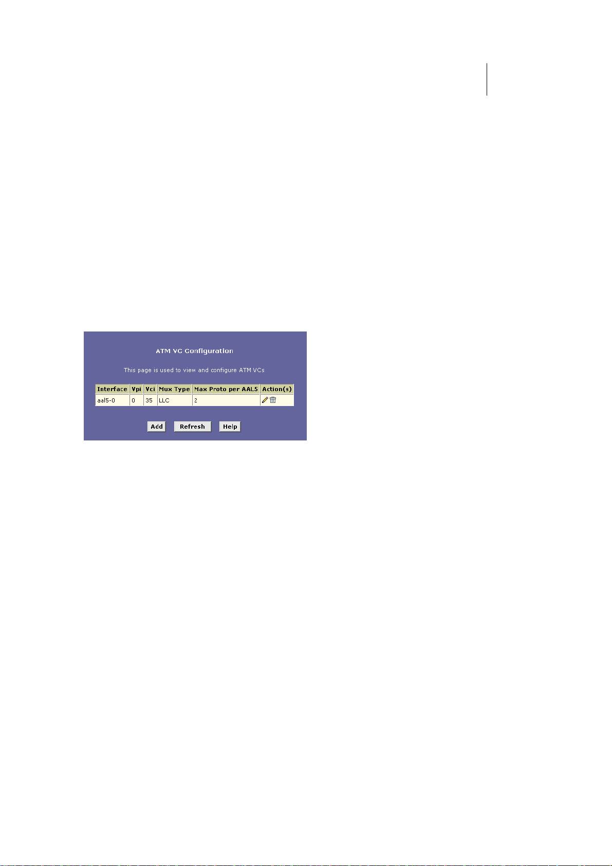
ATL Telecom User Guide
AM30
9
5
Configuring the ATM Virtual Circuit
As your LAN computers access the Internet via the ROUTER , data is exchanged with your
ISP through a complex network of telephone switches, Internet routers, servers, and other
specialized hardware. These various devices communicate using a common language, or
protocol, called Asynchronous Transfer Mode (ATM). On the Wide Area Network (WAN)
that connects you to your ISP, the ATM protocol performs functions like those that the
Ethernet protocol performs on your LAN.
This chapter describes how to configure the ATM virtual circuit (VC). The VC properties
define the path the ROUTER uses to communicate with your ISP over the ATM network.
Viewing Your ATM VC
To view your current configuration, log into Configuration Manager, click the WAN tab,
and then click
in Figure 45.
ATM VC in the task bar. The ATM VC Configuration page displays, as shown
Figure 45. ATM VC Configuration Page
Page 96
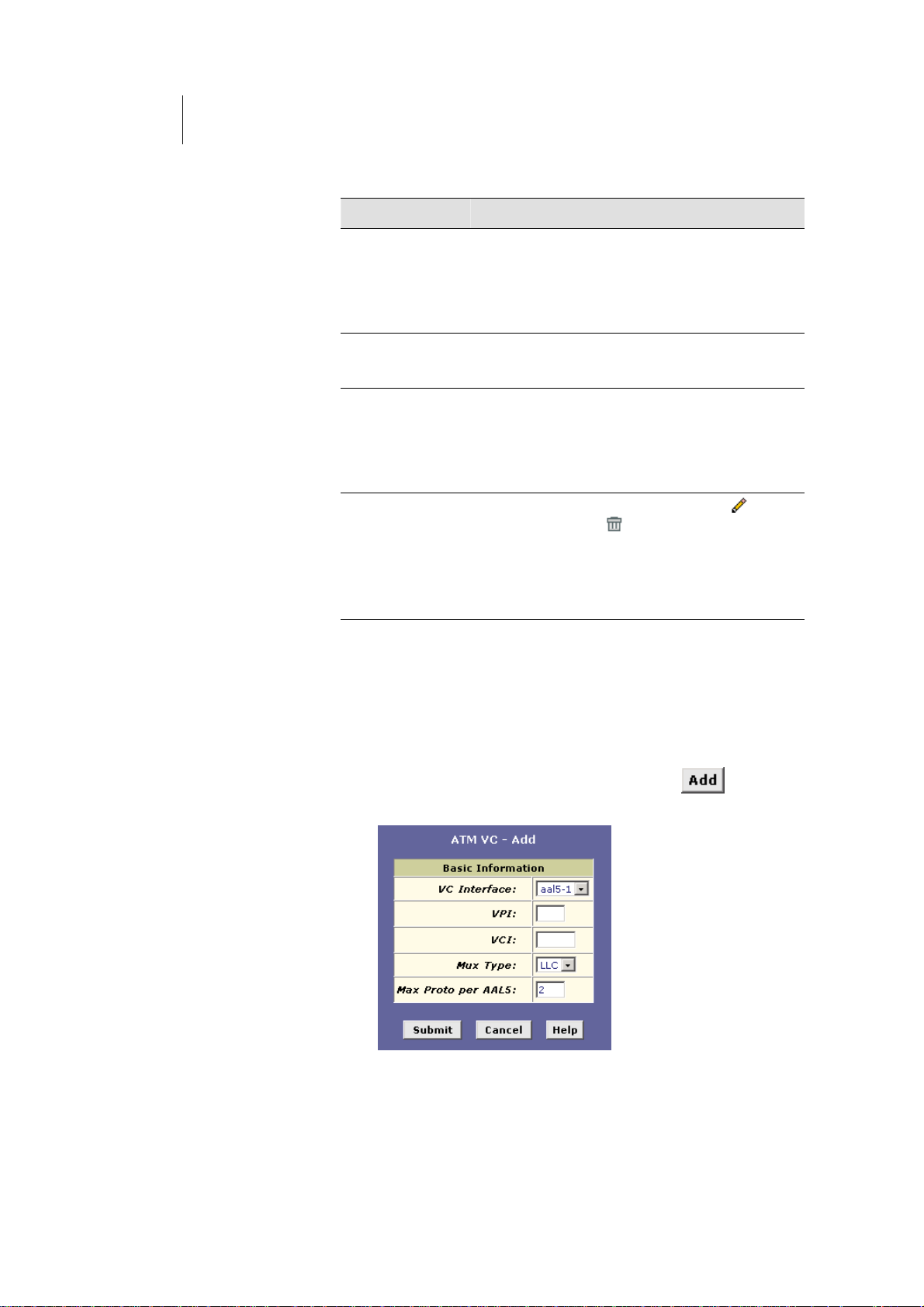
96
ATL Telecom User Guide
AM30
The ATM VC Configuration table displays the following fields (contact your ISP to determine
these settings):
Field Description
Interface
Vpi, Vci, and Mux
Type
Max Proto per
AAL5
Actions
The name of the lower-level interface on which this
VC operates. The low-level interface names are
preconfigured in the software and identify the type
of traffic that can be supported, such as data or
voice. Internet data services typically use an AAL5type interface.
These settings identify a unique ATM data path for
communication between your ADSL/Ethernet router
and your ISP.
If you are using an AAL5-type of interface, this
setting indicates the number of higher-level
interfaces that the VC can support (the higher level
interfaces can be PPP, EoA, or IPoA interfaces).
Contact your ISP to determine which connection
protocol(s) they require.
Displays icons you can click on to modify (
page 98) and delete ( ) the associated interface.
You cannot delete an ATM interface if another
protocol such as PPP, EoA, or IPoA has been defined
to operate over the ATM interface. Delete the
higher-level interface first, and then delete the ATM
interface.
— see
Adding ATM VCs
You may need to create a VC if none has been predefined on your system or if you use
multiple services with your ISP. Each service may require its own VC. Follow these
instructions to add a VC:
1. From the ATM VC Configuration page, click .
The ATM VC – Add page displays, as shown in Figure 46.
Figure 46. ATM VC – Add Page
Page 97

ATL Telecom User Guide
AM30
9
7
2. Select an interface name from the VC Interface drop-down
list.
3. Enter the VPI and VCI values assigned by your ISP, and
select the mux type from the drop-down list.
4. In the Max Proto per AAL5 text box, enter the number of
protocols that the ISP indicated that you will need to
configure (usually only one).
5. Click
6. When the confirmation page displays, click
.
to
return to the ATM VC Configuration page.
The new interface should now display in the ATM VC
Configuration table.
N interface, or modifYou may need to create a new WA y an existing interface, so that it
uses the new VC. See the instructions for configuring a PPP (Chapter 0), EoA (Chapter 0), or
IPoA (Chapter 13) interfaces, depending on the type you use to communicate with your ISP.
You can verify that the new settings work by attempting to access the Internet from a
LAN/USB computer. Contact your ISP for troubleshooting assistance.
7. When you have verified that the new settings work properly,
click the Admin tab, and then click Commit & Reboot in the
task bar.
8. Click
memory.
to save your changes to permanent
Page 98
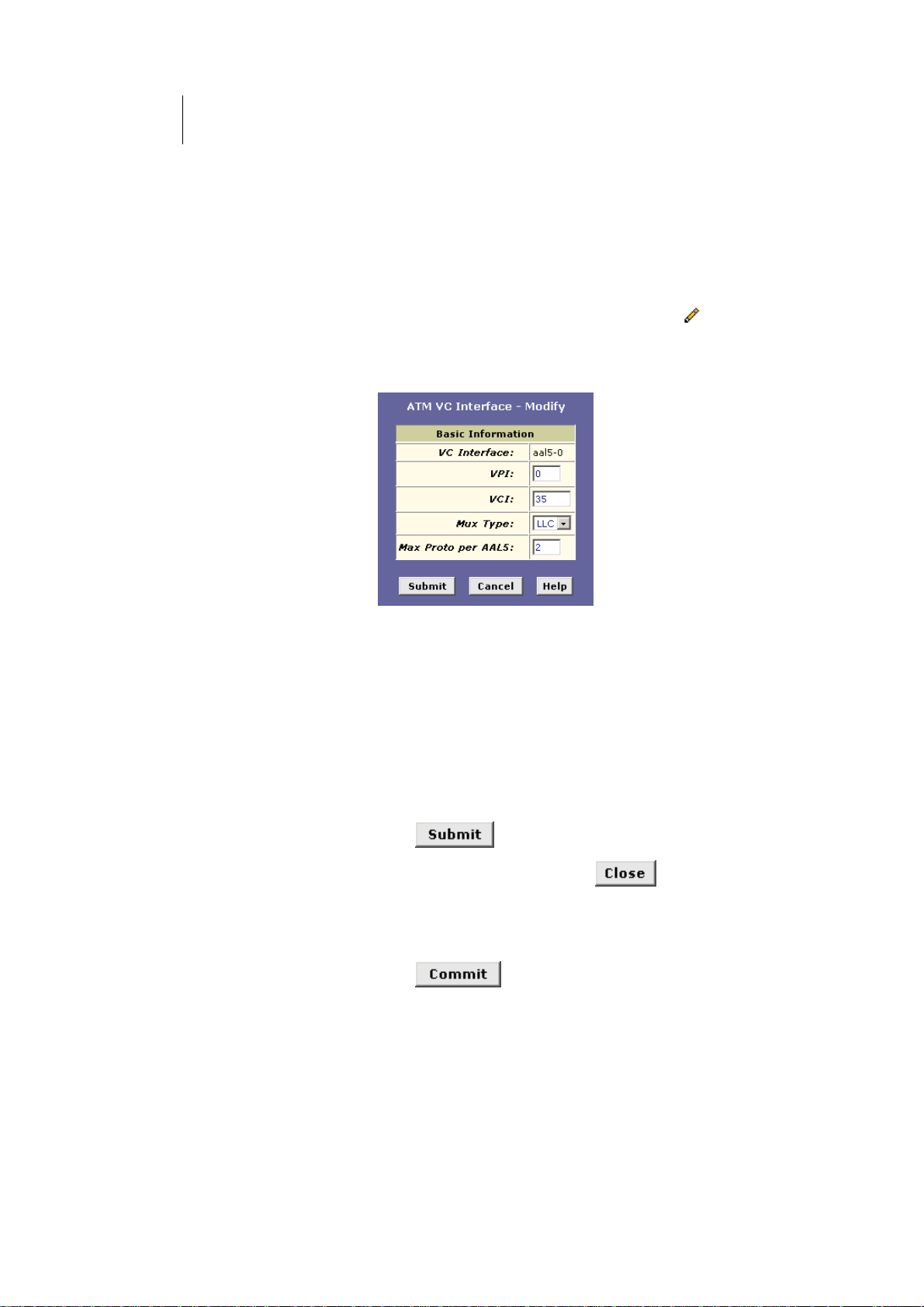
98
ATL Telecom User Guide
AM30
Modifying ATM VCs
Your device may already be preconfigured with the necessary ATM VC properties, or the
table may contain placeholder values that you must change before using the device.
Contact your ISP to determine your ATM VC values. Follow these instructions to modify a
preconfigured VC:
1. From the ATM VC Configuration page, click in the
Actions column for the interface you want to modify.
The ATM VC Interface – Modify page displays, as shown
in Figure 46.
Figure 47. ATM VC Interface – Modify Page
2. Enter the new VPI and VCI values, select the MUX type, or
change the maximum number of protocols that the VC can
carry, as directed by your ISP.
You cannot modify the interface type over which an
existing VC operates (aal5-0, for example). If you want to
change the interface type, you must delete the existing
interface, create a new one, and select the desired
interface type.
3. Click .
4. On the confirmation page, click
ATM VC Configuration page.
5. Click the Admin tab, and then click
task bar.
6. Click
memory.
to save your changes to permanent
to return to the
Commit & Reboot in the
You can verify that the new settings work by attempting to access the Internet from a
LAN/USB computer. Contact your ISP for troubleshooting assistance.
Page 99
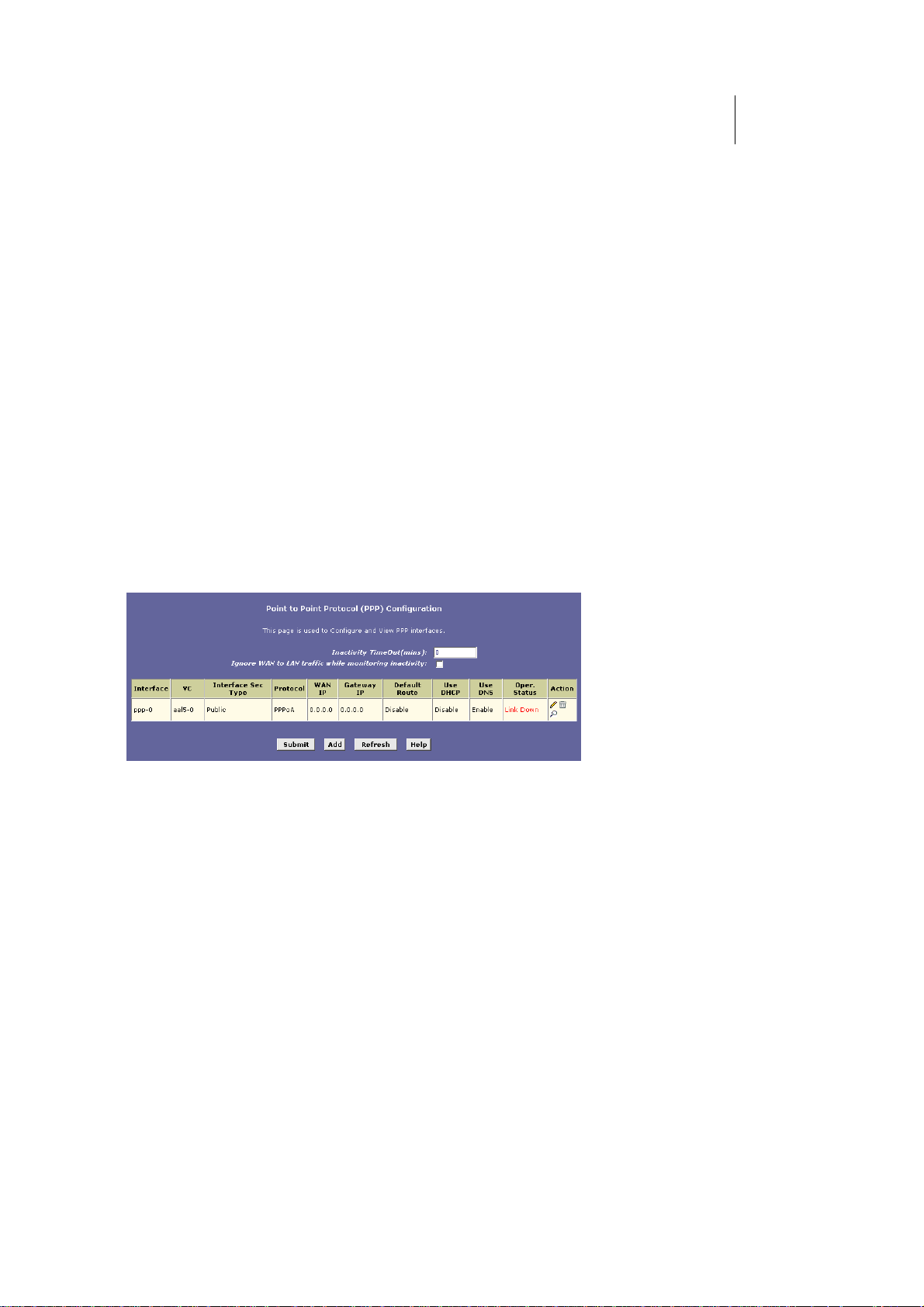
ATL Telecom User Guide
AM30
9
9
Configuring PPP Interfaces
When powered on, the ROUTER initiates a connection through your DSL line to your ISP.
The point-to-point (PPP) protocol is commonly used between ISPs and their customers to
identify and control various communication properties, including:
fIdentifying the type of service the ISP provides to a
given customer
fIdentifying the customer to the ISP through a
username and password login
fEnabling the ISP to assign Internet information to the
customer’s computers
Your ISP may or may not use the PPP protocol. Contact your ISP to determine if you will
need to change the default settings in order to connect to their server.
Viewing Your Current PPP Configuration
To view your current PPP setup, log into Configuration Manager, click the WAN tab, and
then click
as shown in Figure 48.
PPP in the task bar.The Point to Point Protocol (PPP) Configuration page displays,
Figure 48. Point to Point Protocol (PPP) Configuration Page
PPP is configured as a group of software settings associated with the ADSL port. Although
the device has only one physical ADSL port, the ROUTER can be defined with more than
one group of PPP settings. Each group of settings is called a PPP interface and is given a
name, such as ppp-0, ppp-1, etc.
Page 100

100
ATL Telecom User Guide
AM30
You can configure the following settings on the PPP Configuration page:
fInactivity TimeOut: The time in minutes that must
elapse before a PPP connection times-out due to
inactivity.
fIgnore WAN to LAN traffic while monitoring
inactivity: enabled, data traffic traveling in the
incoming direction—from the WAN port to the LAN
port—will not count as activity on the WAN port; i.e.,
the occurrence of WAN to LAN traffic will not
prevent the connection from being terminated due to
lack of activity in the LAN to WAN direction.
The PPP Configuration Table displays the following fields:
Field Description
Interface
VC
Interface Sec Type
Protocol
WAN IP
Gateway IP
Default Route
The predefined name of the PPP interface.
The virtual circuit over which this PPP data is sent.
The VC identifies the physical path the data takes to
reach your ISP. See Chapter 0 for more information.
The type of firewall protections that are in effect on
the interface (public, private, or DMZ):
o A public interface connects to the Internet (PPP
interfaces are typically public). Packets received
on a public interface are subject to the most
restrictive set of firewall protections defined in
the software.
o A private interface connects to your LAN, such
as the Ethernet interface. Packets received on a
private interface are subject to a less restrictive
set of protections, because they originate within
the network.
o The term DMZ (de-militarized zone), in Internet
networking terms, refers to computers that are
available for both public and in-network
accesses (such as a company's public Web
server). Packets incoming on a DMZ interface -whether from a LAN or external source -- are
subject to a set of protections that is in between
public and private interfaces in terms of
restrictiveness.
The type of PPP protocol used. Your ISP may use PPPover-Ethernet (PPoE) or PPP-over-ATM (PPoA).
The IP address currently assigned to your WAN (DSL)
port by your ISP.
The IP address of the server at your ISP that provides
you access to the Internet. See “Hops and gateways”
on page 84 for a description of gateway addresses.
Indicates whether the ADSL/Ethernet router should
use the IP address assigned to this connection as its
default route. Can be Enabled or Disabled. See
Chapter 0 for an explanation of default routes.
 Loading...