

Page 1

OM100 Optical Multiplexer
USER GUIDE
ATL part no: 1/352/001/610
Issue 03 – March 2003
Page 2
The information in this document is confidential to
ATL Telecommunications Ltd and may not be
disclosed or reproduced in whole or in part without
their written consent
© ATL Telecommunications Ltd 2002
ATL USER GUIDE
OM100 Optical Multiplexer
1ATL USER GUIDE
OM100 Optical Multiplexer
This document does not claim integrity and accuracy in detail.
This documentation is protected by copyright.
Changes to this document may be made at anytime.
Caution – hazardous voltages inside
The unit contains no user serviceable parts. Do not open the unit.
Caution – Laser Product
The Optical Interface is classified as a CLASS 1 LASER PRODUCT.
Manufacturers Declaration*
ATL Telecom Ltd. declares that this product is in conformity with the
essential requirements of the ‘R & TTE directive 1999/5/EC’.
Service Repair Statement
This product is not designed for field service repair, and in all cases should
be returned to ATL Telecom Ltd in the event of component failure.
*A copy of the Declaration of Conformity is available upon request
from ATL Telecommunications Limited.
Page 3

3.5.2.3 Problems with the optical port 18
3.5.4 Optical performance 19
3.5.5 Range 20
3.5.6 Protection switching 21
3.5.7 Troubleshooting - Optical transmission 22
3.6 CONNECTING TO THE E1 USER PORTS 23
3.6.1 Pin assignments 23
3.6.2 Configuring the user ports 24
3.6.2.1 Troubleshooting user ports 28
3.7 FRONT PANEL 29
3.7.1 Controls 29
3.7.1.1 Disabling the Front Panel Controls 29
3.7.1.2 Programming Mode 29
3.7.1.3 Resetting to Factory Default Configuration 29
3.7.1.4 Setting Loops 30
3.7.2 Indicators 30
6.1 NAVIGATION SCREENS 39
6.2 INFORMATION SCREENS 40
6.3 CONFIGURATION SCREENS 41
6.3.1 Entering data 41
6.3.2 Moving between check boxes 41
6.3.3 Turning functions on and off 41
6 MENU SCREEN 39
5 LOGOFF PROCEDURE 37
4 LOGON PROCEDURE 33
1.1 DUST ON THE OPTICAL CONNECTIONS 7
2.1 DESCRIPTION 9
2.2 MECHANICAL CONCEPT – DESKTOP UNIT 9
3.1 CHOOSING A SUITABLE LOCATION 11
3.1.1 Wall mounting the desktop unit 11
3.2 CABLES MUST BE CONNECTED BEFORE APPLYING POWER 11
3.3 CONNECTING POWER TO THE UNITS 11
3.3.1 DC input connector 12
3.4 CONNECTING TO THE TERMINAL PORT 12
3.4.1 Local terminal port connector 12
3.4.2 Cable requirements 13
3.4.3 VT100 Interface Settings 13
3.4.4 Local terminal port configuration 14
3.5 CONNECTING TO THE OPTICAL PORT 15
3.5.1 Saftey warning 15
3.5.2 Optical port location 15
3.5.2.1 Dual fibre multi-mode and dual fibre single-mode 15
3.5.2.2 Single fibre, single-mode 16
3.5.2.3 1+1 single fibre, single-mode 16
3.5.3 Types of fibre optic connector 18
3.5.3.1 FC-SPC 18
3.5.3.2 ST 18
3 INSTALLATION 11
2 INTRODUCTION 9
1 GUIDANCE NOTES CONCERNING DEMONSTRATION
INSTALLATIONS 7
ATL USER GUIDE
OM100 Optical Multiplexer
32 ATL USER GUIDE
OM100 Optical Multiplexer
Page 4

6.3.4 How radio buttons work 42
7.1 ALARMS 44
7.1.1 Alarm status screen 44
7.1.2 Alarm history screen 46
7.1.3 Alarm severity level settings 48
7.1.3.2 Alarm sources 50
7.2 CONFIGURATION 51
7.2.1 Master/Slave configuration 51
7.2.2 User port configuration 53
7.2.3 Protection switching configuration 54
7.2.4 Date and time set-up 56
7.2.5 Subsystem names 58
7.2.6 Monitoring mode 59
7.2.7 Download 61
7.2.7.1 Initiating a software download 62
7.2.8 Local terminal communications set-up 63
7.2.8.1 Procedure to follow when changing settings 64
7.2.9 Reboot 65
7.2.10 Front Panel 66
7.3 INFORMATION 67
7.4 LOGOUT 68
7.5 PERFORMANCE 69
7.5.1 Optical performance 69
7.5.2 User port performance 71
7.6 SECURITY (CHANGE PASSWORDS) 73
7.7 TEST 74
7 MENU TOPOLOGY 43
ATL USER GUIDE
OM100 Optical Multiplexer
54 ATL USER GUIDE
OM100 Optical Multiplexer
7.7.1 Setting data loopbacks 74
9.1 LVD SAFETY STATEMENTS 79
9.2 SAFETY STATEMENTS 79
9.3 TELECOMMUNICATION SPECIFICATIONS 79
1 GUIDANCE NOTES CONCERNING DEMONSTRATION
INSTALLATIONS 7
2 INTRODUCTION 9
3 INSTALLATION 11
APPENDIX B - FRONT PANEL PROGRAMMING 85
APPENDIX A - ORDERING INFORMATION 83
10 GLOSSARY OF TERMS 81
9 SAFETY STATEMENTS AND COMPLIANCE NOTES 79
8 SPECIFICATIONS 75
Page 5

ATL USER GUIDE
OM100 Optical Multiplexer
7
Whilst this unit will function as expected in normal operation, there have been some cases
during testing where the operator has required some guidance. We have therefore provided
some guidance in this section to help users to avoid the most common problems.
1.1 DUST ON THE OPTICAL CONNECTIONS
Repeated insertions of optical connectors to the unit’s optical port may cause a build up of
dust on the face of the fibre resulting in the units failing to communicate. This can be avoided
by the correct handling of optical connectors. The optical fibre should never be placed,
unprotected, on a surface where dust can be attracted onto the end of the fibre cord. If this
precaution isn’t taken, then the dust may pass from the end of the fibre to the internal surface
of the optical port when the fibre is inserted. The dust will then become difficult to remove.
As a further precaution against dust entering the optical port in this way, the face of the
optical fibre must be wiped before the connector is inserted into the optical port. It is also
advisable to discharge a sharp blast of compressed air to the optical port itself. This procedure
must be carried out every time an optical cable is connected to the unit to ensure that it
functions correctly. Failure to do this may cause degradation to the performance of the unit
including the possibility of complete failure. (We recommend that a can of compressed air and
a small quantity of optical wipes are made available)
1 GUIDANCE NOTES CONCERNING DEMONSTRATION
INSTALLATIONS
1
6 ATL USER GUIDE
OM100 Optical Multiplexer
4 LOGON PROCEDURE 25
5 LOGOFF PROCEDURE 29
6 MENU SCREEN 31
7 MENU TOPOLOGY 35
8 SPECIFICATIONS 61
9 SAFETY STATEMENTS AND COMPLIANCE NOTES 65
10 GLOSSARY OF TERMS 67
Page 6
ATL USER GUIDE
OM100 Optical Multiplexer
9
2.1 DESCRIPTION
The ATL OM100 provides a cost effective and manageable approach to delivering digital lines
into customer premises. The OM100 takes four co-directional 2.048Mbps G.703 signals and
condenses them onto a single or dual optical fibre link – providing a highly integrated solution
with low commissioning costs.
Its flexible data format and comprehensive range of monitoring functions make ATL’s OM100
the ideal choice for low maintenance installations.
Comprehensive menus allow quick and easy access to all statistical and control information.
A VT100 terminal connection is provided for localised management.
Remote management is fully supported. Push button configuration is provided for those
preferring a quick set up.
The customer unit has all the functionality necessary to provide leased line and PABX
connectivity. There are minimal stock options. One unit covers most requirements.
The unit is transparent to frame structure and timing independent,making it ideal for all
EI delivery, including provisioning of Primary Rate ISDN.
Power is supplied to the Desktop unit via an exchange battery connection. An external mains
to DC converter is supplied for those preferring a mains powered unit.
2.2 MECHANICAL CONCEPT – DESKTOP UNIT
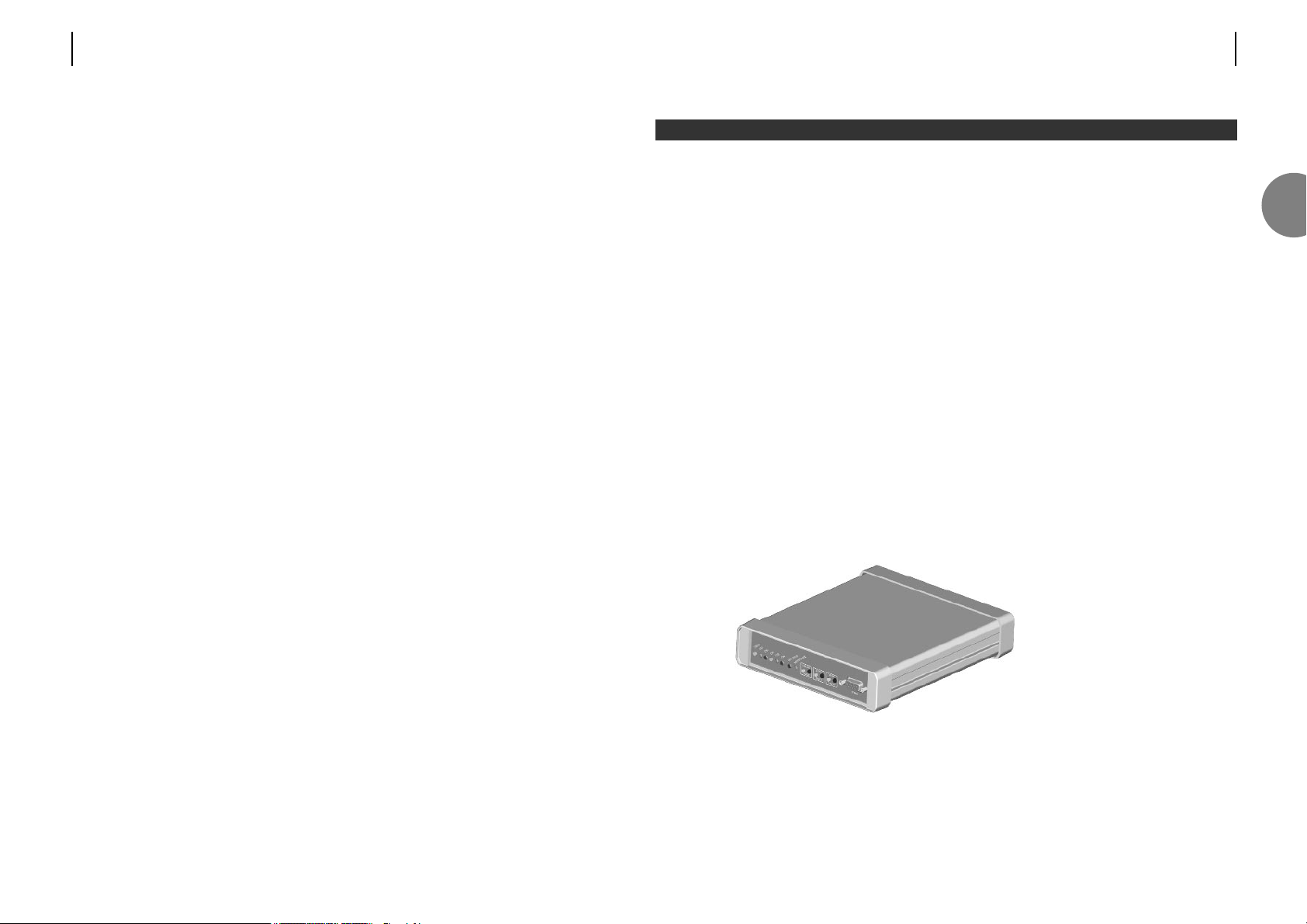
The line equipment desktop
unit is accommodated in a
metal moulded housing.
Indication elements are
located on the front of the
unit. All network connections
are at the rear, whilst
management connections are
at the front of the unit.
The dimensions of the
desktop unit are (W x H x D)
169 x 49 x 206mm. FIGURE 2.1 DESKTOP UNIT
2 INTRODUCTION
2
8 ATL USER GUIDE
OM100 Optical Multiplexer
Page 7

3.1 CHOOSING A SUITABLE LOCATION
Choose a cool, dry location away from direct sunlight. A cold, air conditioned room will give
maximum service life.
The desktop unit can be placed on a shelf, fixed to a wall, or housed in a racking enclosure.
3.1.1 Wall mounting the desktop unit
Two wall mounting brackets are supplied with the desktop unit. The procedure for attaching
the unit to a wall is as follows:
1. Choose a flat, level wall, strong enough to support the weight of the unit.
2. Offer the supplied drilling template to the wall, marking the location of the two
screw holes.
3. Drill the wall with a 5.5mm (7/32") drill bit and tap one of the supplied wall plugs into
each hole.
4. Fit one of the supplied screws into each plug.
5. Hang the unit on these two screws.
3.2 CABLES MUST BE CONNECTED BEFORE APPLYING POWER
This will involve connecting up the relevant cables to the front and rear of the unit. It is
recommended that the user read this manual prior to set-up to gain an understanding of the
operation of both the units and the software used to control the units.
3.3 CONNECTING POWER TO THE UNITS
The power up sequence will begin after power is applied.
Desktop units require -48V dc (or 110/230V ac to an external adaptor).
The unit must be connected to a protective earth using a suitable bonding conductor.
On the desktop unit, there are twelve LED’s: Status, Ch1, Ch2, Ch3, Ch4, Optical 1, Optical 2,
Master, Test, Local loop, Loop back and Remote loop. When power is applied to the unit, the
front panel LED’s are illuminated as follows;
1. All 3 loop button LED’s will illuminate and the Test LED will flash.
2. Loop LED’s extinguish,Status and Master LED’s illuminate briefly.
3. Status and Optical LED’s should then be illuminated only.
The unit will then be in a ready state for customer configuration.
3 INSTALLATION
ATL USER GUIDE
OM100 Optical Multiplexer
11
3
10 ATL USER GUIDE
OM100 Optical Multiplexer
Page 8
ATL USER GUIDE
OM100 Optical Multiplexer
13
3.4.2 Cable requirements
Use a straight through cable to connect your terminal, or modem.
Suitable cables are PC-AT serial port extender cables, or PC-AT serial mouse extender cables.
The serial ports on most terminals and PC’s are configured as DTE interfaces.
3.4.3 VT100 Interface Settings
The default settings for the serial port connection are as follows;
Baud Rate – 19200bps
Data Bits – 8
Parity – None
Stop Bits – 1
Handshake – Xon/Xoff
Signal direction
out in
in out
in out
out in
in out
out in
OM100 connector
(DCE interface)
9 way male D-type
1 –
2 Receive
3 Transmit
4 DTR
5 Ground
6 DSR
7 RTS
8 CTS
9 –
9 way female
D-type
1
2
3
4
5
6
7
8
9
–
Receive
Transmit
DTR
Ground
DSR
RTS
CTS
–
25 way female
D-type
8
3
2
20
7
6
4
5
22
Terminal, or modem connection
(DTE interface)
3
12 ATL USER GUIDE
OM100 Optical Multiplexer
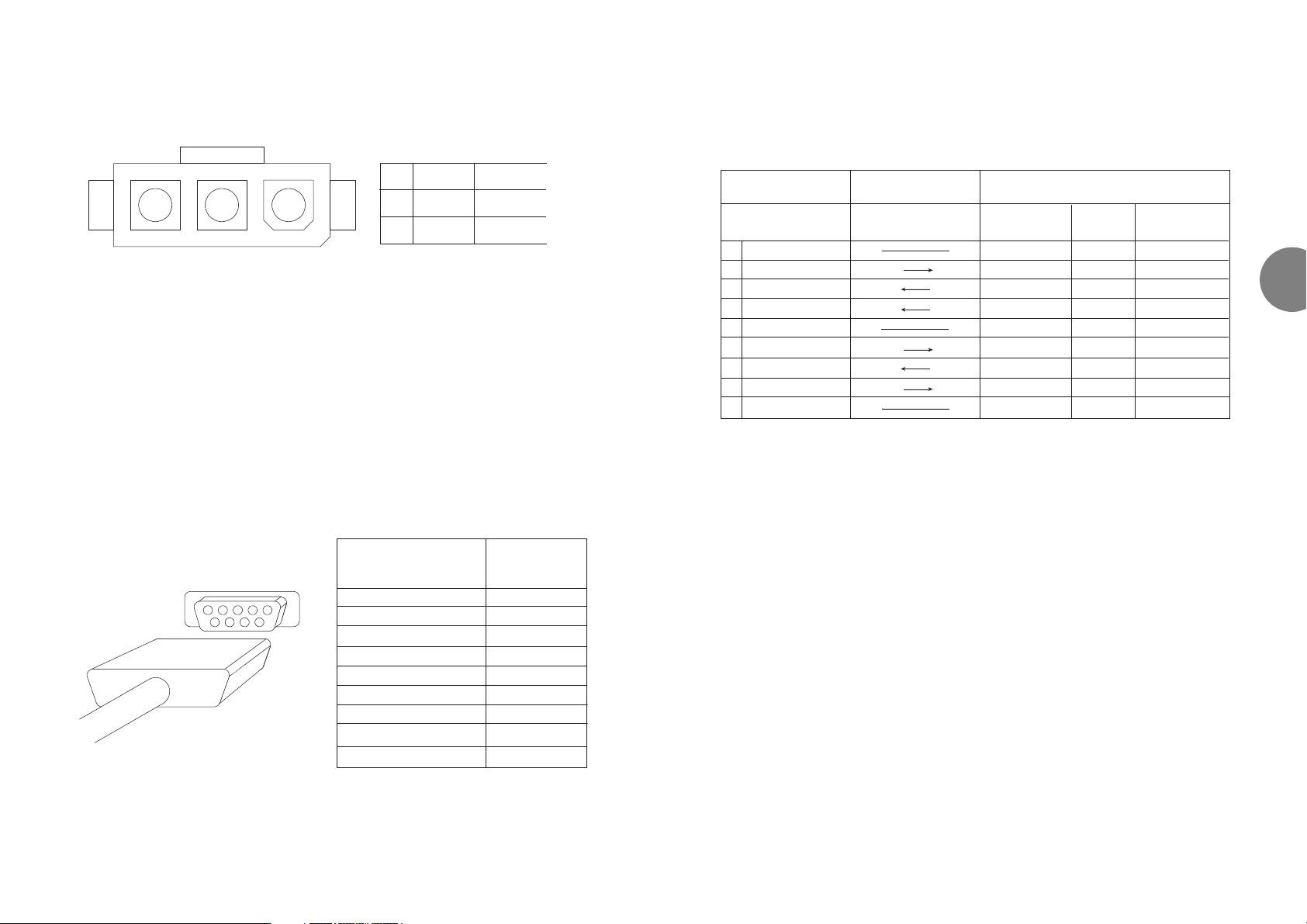
3.3.1 DC input connector
A connection from CGND to earth is required for functional earthing only.
Mating connector
Molex Minifit Junior Receptacle Molex Part Number: 39-01-4031
Molex female contact Molex Part Number: 39-00-0039
NB. An approved DC cable assembly can be purchased from ATL - see appendix A.
3.4 CONNECTING TO THE TERMINAL PORT
To configure the units, a VT100 terminal or PC running a VT100 emulation program must
be connected to the 9-way serial terminal port on the front of the unit. When using a PC,
ATL recommend using the Teraterm software, that can be downloaded via our website.
3.4.1 Local terminal port connector
A 9-way female D-type connector (see figure 3.1) is located on the front panel (labelled TERM)
Note: The local terminal port connector is a
DCE interface. (DCE’s transmit their data on
the wire named RECEIVE).
FIGURE 3.1 LOCAL TERMINAL PORT
Local terminal interface Signal direction
9-way female D-type
(DCE interface)
1 – –
2 Receive out
3 Transmit in
4 DTR in
5 Ground –
6 DSR out
7 RTS in
8 CTS out
9 – –
1 -48V
2 0V
WHITE
RED
3 CGND BLACK
23 1
3
Page 9
ATL USER GUIDE
OM100 Optical Multiplexer
15
3.5 CONNECTING TO THE OPTICAL PORT
3.5.1 Safety warning
Class 1 laser product.
Warning – high level of invisible light.
Never look into the optical port or the optical cable. Permanent eye damage may occur.
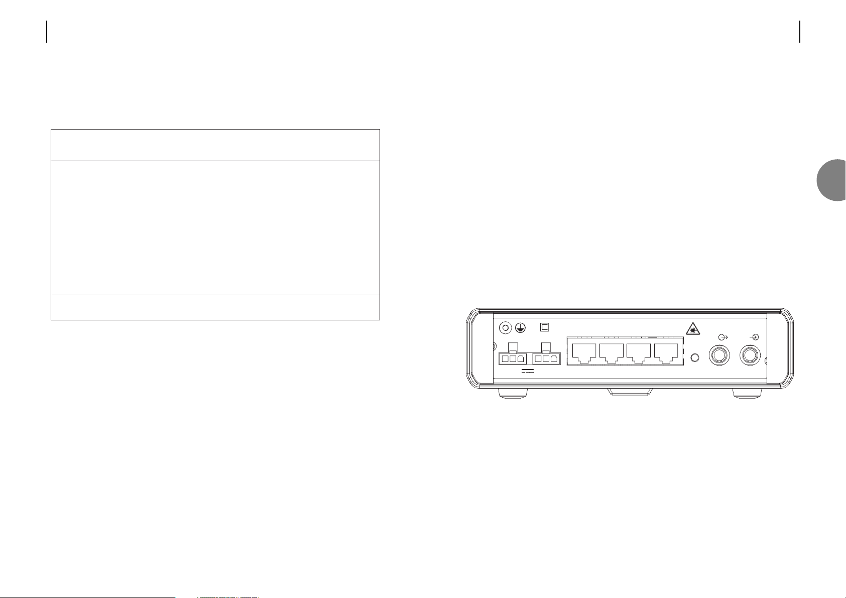
Figures 3.2.1 to 3.2.3 show the rear connection panel of the desktop unit.
In common with most communication lasers, this product produces a high level of light.
Looking directly into the optical port will damage your eyes. Normally the human eye would
respond to bright light by reducing its pupil size. The blink, or aversion reflex would further
limit the amount of damage done. However, the laser light produced is of a very long
wavelength – in the far infrared region of the light spectrum, and unfortunately the human
eye can neither see light of this wavelength, or respond to it. If you look into the optical port,
you will not see the infrared light, but your eyes will be damaged by it.
3.5.2 Optical port location
3.5.2.1 Dual fibre multi-mode and dual fibre single-mode
FIGURE 3.2.1
INFORMATION RELATING TO OM100 DUAL-FIBRE MULTIMODE (1/352/1XX)
Emitted wavelength = 850nm
Maximum output laser radiation < 1mW
Laser classification = Class 1 to EN 60825:1994
OPTICAL LINE
- 48V /80mA
DC 1
DC 2
CH 1 CH 2 CH 3CH
4
BOOT
Rx
Tx
3
14 ATL USER GUIDE
OM100 Optical Multiplexer
3.4.4 Local terminal port configuration
To view or configure the terminal port settings, move to the “Serial Communications” screen
(see section 7). The selection displayed can be altered using the spacebar (See section 6.3).
The factory standard configuration is:
If the baud rate has been set incorrectly, the VT100 terminal will not display characters
correctly. If the setting has been changed, please try setting each baud rate in turn on the
terminal emulator settings.
OM100 Mon 01 Nov 2002 00:29:07
Configuration > Serial Communications
Urgent Alarm:On Non-Urgent Alarm:Off
Baud Rate Data Bits Parity Stop Bits Handshake
2400 ( ) 7 ( ) None (*) 1 None ( )
4800 ( ) 8 (*) Odd ( ) Xon/Xoff (*)
9600 ( ) Even ( )
19200 (*)
Press Return to Accept or Escape to Cancel
F1 Help F3 Previous Menu F4 Main Menu F5 Default
Page 10
ATL USER GUIDE
OM100 Optical Multiplexer
17
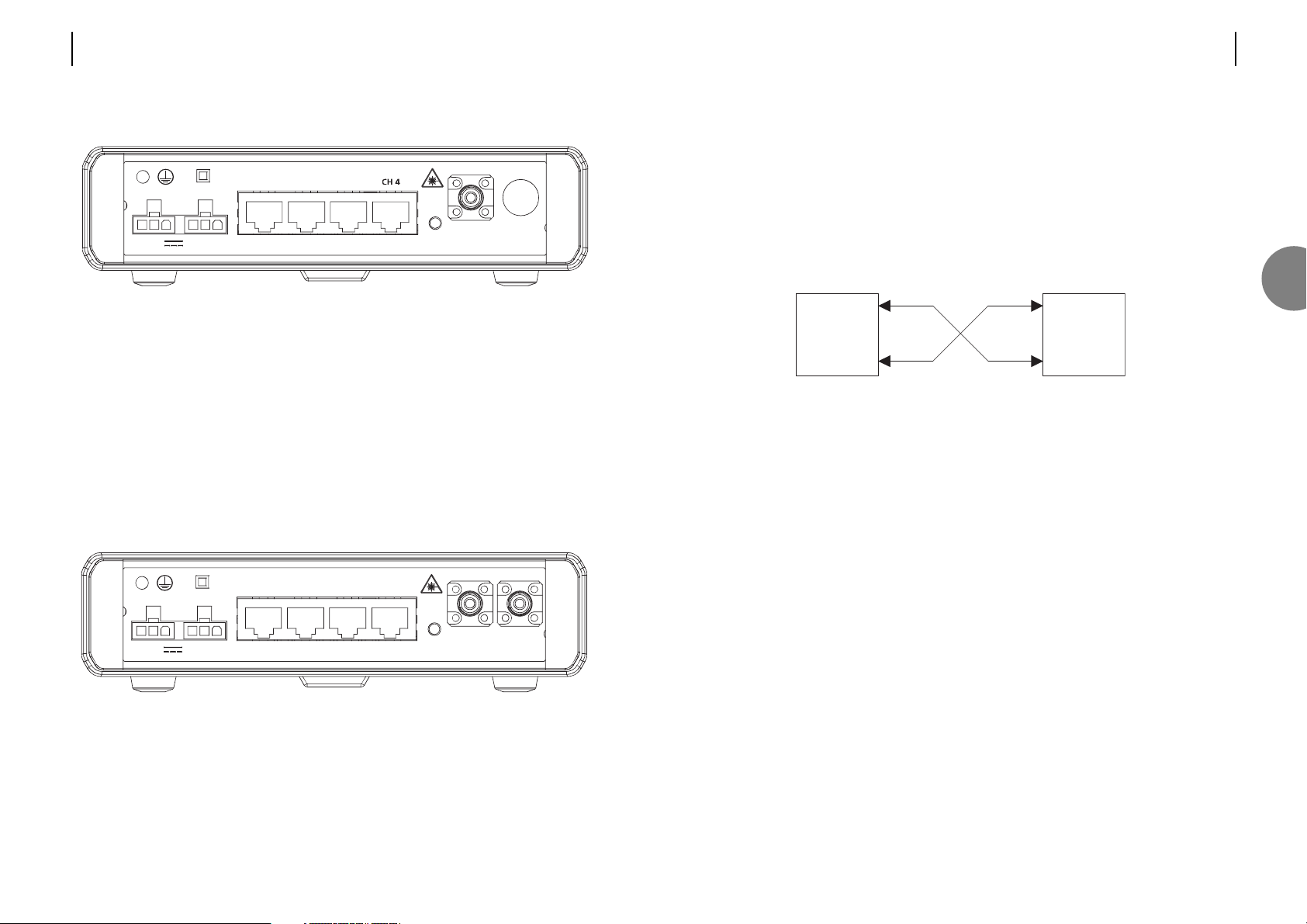
CONNECTING THE OM100 1+1 SF SM OPTICAL FIBRES
The Optical fibres must be connected as in Fig 3.2.4 :
Main Link: Optical Line 1 on the Master unit must be connected to Optical Line 2 on the
Slave unit.
Backup Link: Optical Line 2 on the Master unit must be connected to Optical Line 1 on the
Slave unit.
FIGURE 3.2.4
Slave
Optical 1
Optical 2
st
Optical 1
Optical 2
Master Slave
3
16 ATL USER GUIDE
OM100 Optical Multiplexer
3.5.2.2 Single fibre, single-mode
FIGURE 3.2.2
INFORMATION RELATING TO OM100 SINGLE-FIBRE SINGLE-MODE SLAVE (1/352/3XX)
Emitted wavelength = 1310nm
Maximum output laser radiation < 5mW
Laser classification = Class 1 to EN 60825:1994
INFORMATION RELATING TO OM100 SINGLE-FIBRE SINGLE-MODE MASTER (1/352/4XX)
Emitted wavelength = 1550nm
Maximum output laser radiation < 7mW
Laser classification = Class 1 to EN 60825:1994
3.5.2.3 1+1 single fibre, single-mode
FIGURE 3.2.3
INFORMATION RELATING TO OM100 1+1 SINGLE-FIBRE SINGLE-MODE (1/352/5XX)
Emitted wavelength = 1310nm & 1550nm
Maximum output laser radiation <5mW @ 1310nm & <7mw @ 1550nm
Laser classification = Class 1 to EN 60825:1994
12
OPTICAL LINE
DC 1 DC 2
CH 1 CH 2 CH 3CH
4
BOOT
- 48V /100mA
12
OPTICAL LINE
DC 1 DC 2
CH 1 CH 2 CH 3 CH 4
BOOT
- 48V /100mA
Page 11

ATL USER GUIDE
OM100 Optical Multiplexer
19
3.5.4 Optical performance
NB. All values above are nominal
Optical system
type
Atten. max
Atten. min
P
TX
P
RX
Wavelength
Con. No.
Con. type
Fibre type
Class
Multi-mode
dual fibre
18dB
0dB
-9dBm
-27dBm
850nm
2
ST
G.651
1
Single-mode
single fibre
25dB
0dB
-7dBm
-32dBm
1310/1550nm
1
FC-PC, ST or SC
G.652
1
1+1 single-mode
(single fibres)
25dB
0dB
-7dBm
-32dBm
1310/1550nm
2
FC-PC, ST or SC
G.652
1
Key
Atten. max
Atten. min
PTX
P
RX
Wavelength
Con No
Con type
Fibre type
Class
Link budget
(Maximum
attenuation)
Minimum link
attenuation
Transmit power
Receive
sensitivity
Optical
wavelength
Number of
connectors
Type of
connectors
Preferred fibre
type
Laser
classification
Description
The maximum attenuation allowed for reliable communications.
Attenuation is a characteristic of the optical fibre. The better
quality of optical fibre the longer the available range.
The minimum attenuation allowable for reliable communications.
A figure of 0dB means the unit does not require external
attenuators for short distances.
The amount of light power transmitted by the laser into the
optical fibre.
The minimum amount of light received by the unit for reliable
communications.
Optical wavelength used in transmission.
The number of optical fibres connected to the the unit.
Normally FC-SPC connectors are used on single-mode fibre.
ST connectors being the choice for multi-mode fibre.
Ideally choose cables designed to the stated international
standard. The unit will operate with a variety of cables, however
the range and reliability may be affected. Multi-mode cable has
an inherently larger attenuation figure, and as such has a lower
range. The range differs with the choice of cable.
International organisations have produced classification systems
to indicate the level of optical hazard. Class 1 is the safest.
However, we stipulate the unit is only installed by professionally
trained service personnel.
3
18 ATL USER GUIDE
OM100 Optical Multiplexer
3.5.3 Types of fibre optic connector
3.5.3.1 FC-SPC
This connector is more commonly used on single-mode
cable. To connect – align the centre of the fibre plug with
the centre of the optical connector (on the rear panel).
Push the plug in gently. Rotate to align the keyway.
The plug should now go in a little more. Make sure the
keyway is correctly located by rotating the plug to the left
and to the right. Only a little movement should be
allowed. Once in place secure the plug by turning the
locking ring clockwise. Taking care not to over-tighten the
locking ring – excessive pressure will cause misalignment,
finger tight is more than ample.
FIGURE 3.3
FC-SPC CONNECTOR
3.5.3.2 ST
This connector is commonly used on multi-mode cable. To
connect – align the centre of the fibre plug with the centre
of the connector. Push gently, aligning the slot in the
locking ring, with the round pegs on the connector. Push
fully home, then rotate the locking ring to secure.
FIGURE 3.4
ST CONNECTOR
3.5.3.3 Problems with the optical port
The vast majority of problems are caused by dust contamination of the optical window. Before
installing the optical plug, its end must be cleaned with an approved disposable optical wipe.
The optical connector on the unit must be cleaned by blowing clean (oil and dust free)
compressed air down the centre of the optical connector.
It is important to select the correct type of unit to match the fibre cable installed. Select a
multi-mode unit for operation on multi-mode fibre, or select a single-mode unit for operation
on single-mode fibre.
Page 12

ATL USER GUIDE
OM100 Optical Multiplexer
21
3.5.6 Protection Switching
Note: This option is only available on the OM100 1+1 SF SM units.
Two, single fibre, bi-directional optical modules are housed within the OM100 case. Either of
these links can fully support all traffic between the two units. Should the active fibre link fail,
the OM100 will automatically switch over to the other link, provided that a valid signal is
available.
The following table describes the conditions which may cause a ‘switch’ to occur.
The OM100 1+1 SF SM unit Protection Switching options, all default to be enabled.
Description
Turns on/off the 1+1 protection switching.
Switch to another link upon detection of LOS
Switch to another optical link upon detection of high bit error
rate exceeding 1x10E-3
The unit will perform a switch if the error rate on the optical
link within any 15 minute period exceeds 1x10E-7.
The unit will perform a switch if the error rate on the optical
link within any 24 hour period exceeds 1x10E-9.
Field
Enable
Switch on LOS
Switch on BER > 10E-3
Switch On Medium Term
Errors > 10E-7
Switch On Long Term Errors >
10E-9
OM100 Mon 01 Nov 2002 00:41:29
Config > Protection Switching
Urgent Alarm:On Non-Urgent Alarm:Off
Enable [X]
Switch On LOS [X]
Switch On BER > 10E-3 [X]
Switch On Bad Medium Term Errors > 10E-7 [X]
Switch On Bad Long Term Errors > 10E-9 [X]
Press Return to Accept or Escape to Cancel
F1 Help F3 Previous Menu F4 Main Menu
3
20 ATL USER GUIDE
OM100 Optical Multiplexer
3.5.5 Range
The range achieved will depend upon the optical fibre used. The better the quality of fibre,
the further the range achieved. Typical figures given below:
Range = Link budget – Connector losses – Splice losses
Attenuation
Note: In the above figures, the attenuation of both the splices and optical connectors has
been assumed to total 1.0 dB.
Id
Cable A
Cable B
Cable C
Attenuation
0.35 dB/Km
0.40 dB/Km
2.40 dB/Km
Range
65.7 Km
57.5 Km
7.1 Km
Fibre Type
Premium single-mode optical fibre
Standard single-mode optical fibre
Standard Multimode optical fibre
Page 13
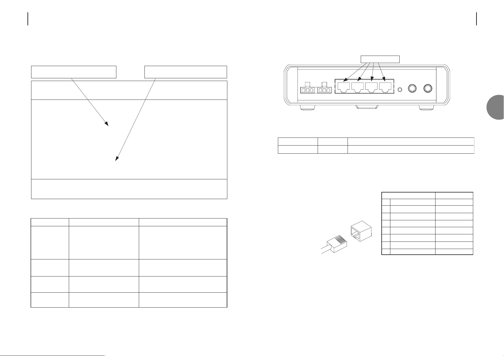
3.6 CONNECTING TO THE E1 USER PORTS
FIGURE 3.5 USER PORT LOCATIONS
Each of the four user ports has the same group of common components:
Note: The 120Ω connection is also known as balanced G.703.
3.6.1 Pin assignments
The 8 way RJ45 connectors present a balanced
120Ω Interface conforming to the G.703 standard.
Cables are normally wired ‘crossed-over’.
The transmit pair, on pins 1 & 2,
connect to the receive pair of
the terminal equipment
(pins 4 & 5).
8-way RJ45 connector Signal direction
1 Transmit a out
2 Transmit b out
3 Transmit ground –
4 Receive a in
5 Receive b in
6 Receive ground –
7 not used –
8 not used –
Component
RJ45 connector
Marking Function
Transmit and receive G.703 data, with 120Ω impedance.
1~ 4
four EI user ports
3
ATL USER GUIDE
OM100 Optical Multiplexer
2322 ATL USER GUIDE
OM100 Optical Multiplexer
3.5.7 Troubleshooting - Optical Transmission
Use the Performance > Optical Transmission Line screen to quickly identify faults.
Alarm
LOS detected
BER>10E-6
BER>10E-3
Lazer Fault
Problem
Incoming signal is not present
(LOS - Loss Of Signal)
Small number of bit errors on the
optical port
High number of bit errors on
optical port
Optical transmission power out
of range
Cause
• Optical cable is broken
• Optical cable is faulty
• Remote partner unit not powered on
• Dirt on optical connectors
• Dirt on optical counters
• Optical cable too long
• Dirt on optical connectors
• Optical cable too long
• Hardware fault
OM100 Mon 01 Nov 2002 00:53:36
Performance > Optical
Urgent Alarm:Off Non-Urgent Alarm:On
Subsystem: LT
Port: Main Link Backup Link Active [ ]
Laser Fault [ ] BER > 10E-3 [ ]
LOS Detected [ ] BER > 10E-6 [ ]
Line Code Violations 0 Trip Counter 0
Available Seconds 491 Trip Counter 491
Unavailable Seconds 0 Trip Counter 0
Severely Errored Seconds 0 Trip Counter 0
Errored Seconds 0 Trip Counter 0
Error Free Seconds 491 Trip Counter 491
Press Escape to Exit
F1 Help F3 Previous Menu F4 Main Menu F5 Previous Link F6 Next Link
F7 Previous Subsystem F8 Next Subsystem F9 Reset Trips
F10 Reset System Counters
LOS indicates that no signal is present
Counters start when unit is powered.
Page 14
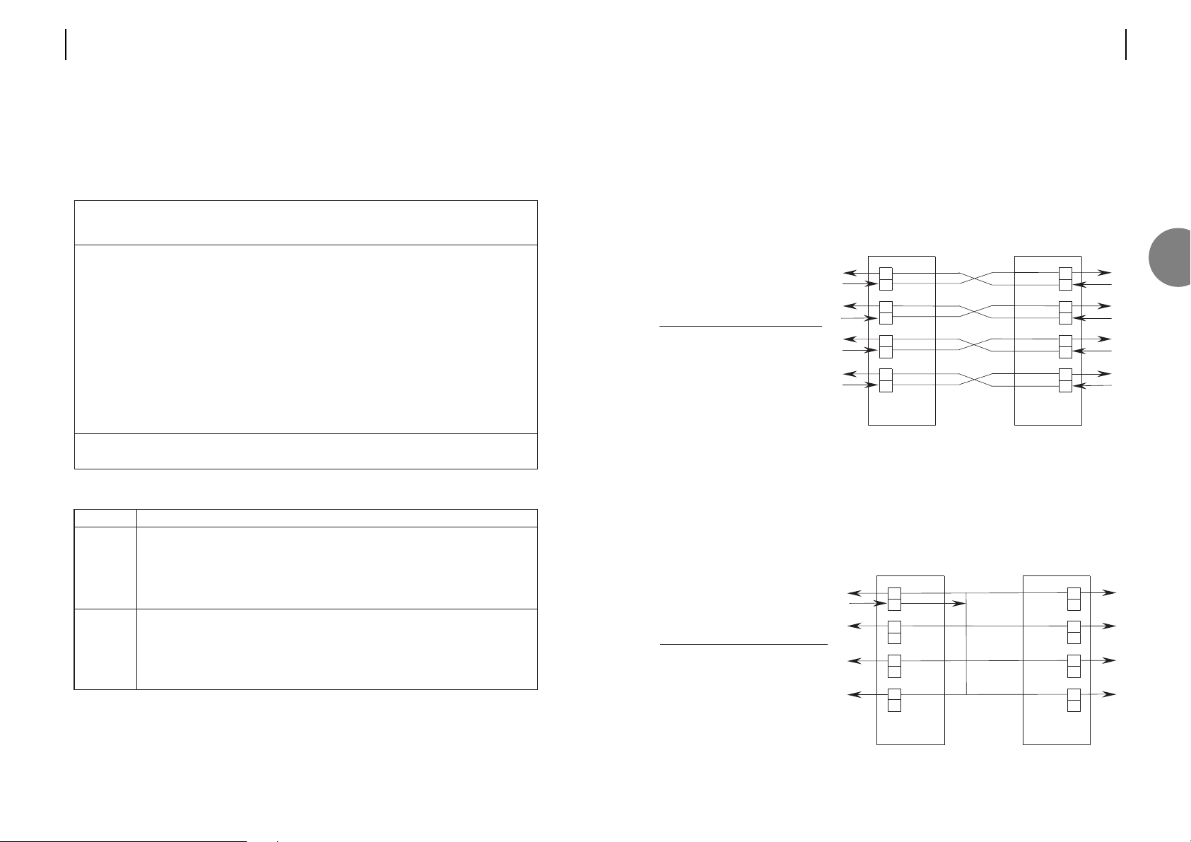
Operating The OM100 in an SDH Environment
Note: This section describes a feature of the OM100 for advanced users only. The default
mode of operation will suit most applications.
In its default mode, the OM100 is purely plesiochronious. The four E1 user ports can transmit
and receive data at (slightly) differing rates. Each, and every clock is truly independent of the
others. E1 links can be sourced from the same timing source, up to eight independent timing
sources, or a mixture of both.
Network operation for clock synchronisation at the PDH end nodes requires selection of the
"lock clock" option from the user port configuration screen. External reference timing is
derived from user port one. Transmit clocks are re-timed and synchronised to the received
clock at the master unit on user port one.
SDH Operation Timing
RX
TX
RX
TX
RX
TX
TX
PORT1
PORT2
PORT3
Master unit
RX
TX
TX
RX
TX
RX
TX
PORT1
PORT3
PORT4
Slave unit
RX
PORT4
RX
PORT2
Lock Clock
Enable to Reference
Port 1 [X]
Port 2 [X] [X]
Port 3 [X] [X]
Port 4 [X] [X]
RX
TX
RX
TX
RX
TX
RX
TX
PORT1
PORT2
PORT3
PORT4
Master unit
RX
TX
RX
TX
RX
TX
RX
TX
PORT1
PORT2
PORT3
PORT4
Slave unit
Lock Clock
Enable to Reference
Port 1 [X]
Port 2 [X] [ ]
Port 3 [X] [ ]
Port 4 [X] [ ]
ATL USER GUIDE
OM100 Optical Multiplexer
2524 ATL USER GUIDE
OM100 Optical Multiplexer
3.6.2 Configuring the user ports
The unit is supplied with all four user ports enabled. Disabled ports block traffic, replacing it
with an AIS pattern. To configure the ports, you must logon to the management port as
described in section 4, and follow the menus to ‘Configuration->User Port’ as shown in
section 7. Section 6 explains how to change the data on the configuration screen.
User ports can be configured by connecting a terminal to either the master, or slave unit. If the
configuration is carried out before the optical connection is made, the parameters stored in
the master unit will overwrite those stored in the slave.
Function
A disabled user port will prevent the customer from gaining useful access.
AIS is continually transmitted both towards the customer and the exchange.
The incoming traffic is blocked, no monitoring takes place, and no response
functions are active. Disabling a port disconnects it logically from the network.
An enabled (default) port will give the customer full access.
In its default mode (off), the OM100 is purely plesiochronious. The E1 user ports
can transmit and receive data at (slightly) differing rates. Each, and every clock is
truly independent of the others.
When on, transmit clocks are re-timed and synchronised to the received clock at
the master unit, on user port one.
Field
Enable
Lock Clock
to Ref.
OM100 Mon 01 Nov 2002 00:34:32
Config > User Ports
Urgent Alarm:On Non-Urgent Alarm:Off
Subsystem: LT
Lock Clock
Enable to Reference
Port 1 [X]
Port 2 [X] [ ]
Port 3 [X] [ ]
Port 4 [X] [ ]
Press Return to Accept or Escape to Cancel
F1 Help F3 Previous Menu F4 Main Menu
3
Page 15
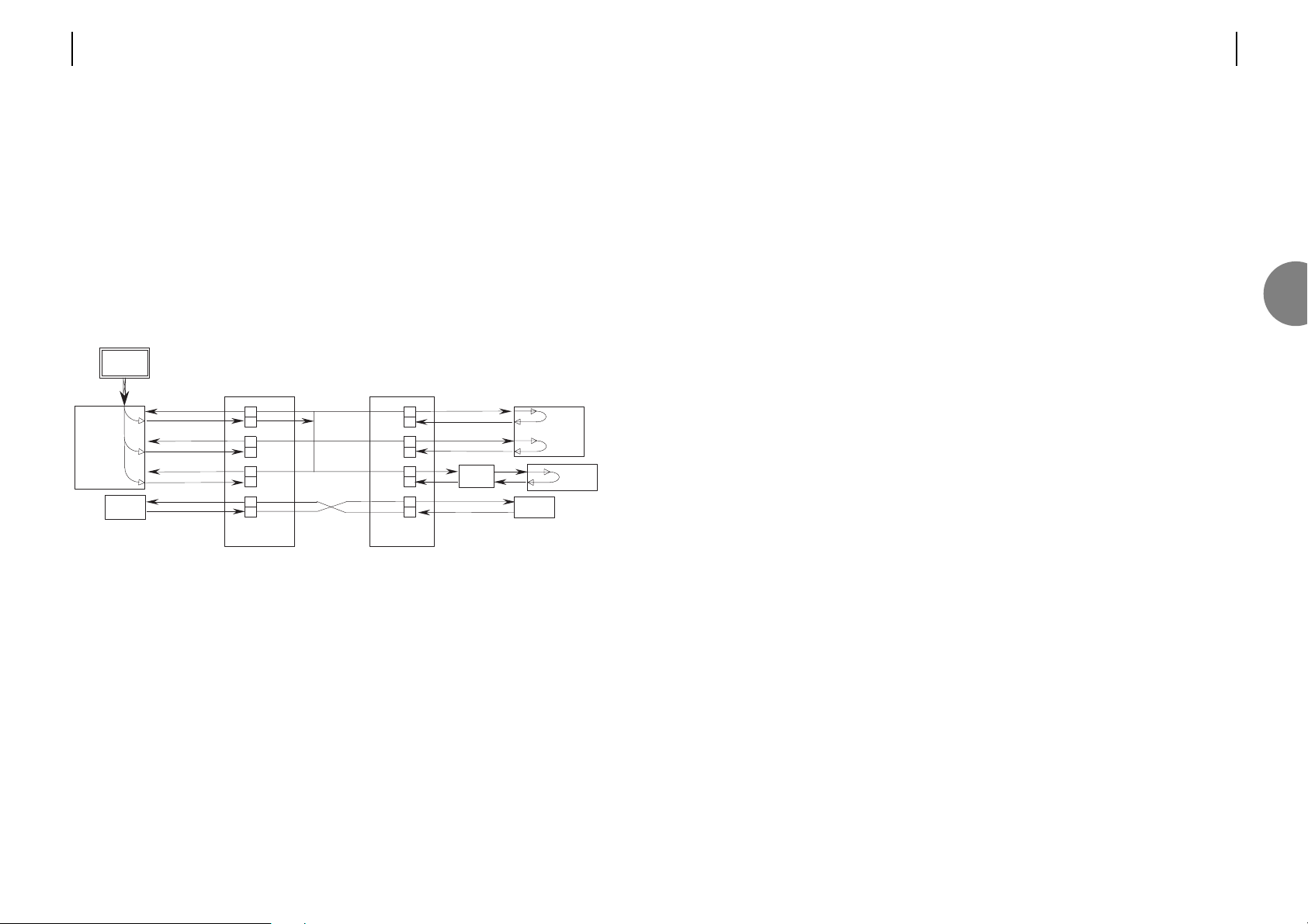
The router connection is configured independently, so its transmit clock could either be
looped, or derived from its own internal clock source.
Of course it is not mandatory to use an external reference clock at the PDH interface, so the
above example could be equally configured to use independent timing for all channels. The
choice on whether to use the "lock clock" option, or not depends upon how the rest of the
network has been configured.
ATL USER GUIDE
OM100 Optical Multiplexer
2726 ATL USER GUIDE
OM100 Optical Multiplexer
Notes:
1. The "lock clock" option is set on a per port basis. Any number of ports may be locked to
the timing reference on port 1, whilst other ports may be timed independently. For example,
ports 1, 2 & 3 may be locked to the timing reference, whilst port 4 remains independent.
2. On the receive side, each "locked" E1 user port derives its own timing from the incoming
E1 signal. This is re-timed to the master reference clock on port 1 before onward transmission.
This permits some flexibility within the terminating equipment. Of course the DTE must be
configured for looped timing, with its transmit clock derived from the timing it receives from
the OM100.
Example network
Notes:
There is no need for a master reference clock on the customer's equipment. However, special
attention must be paid to the clocking scheme used. The customer's equipment must either
be configured for looped timing, or to use a master clock from one of the ports (either is
acceptable). As all "locked" ports use the same clock, a master timing reference can be
derived from any of these ports.
In the above example PABX 1 has each of its two ports configured for looped timing, although
it could have been configured to use a master clock derived from port 1 (or port 2).
PABX 2 has only one user port connection. Again it is configured for looped timing.
The E1 extender can either be configured for looped timing, or operated with independent
timing.
RX
TX
RX
TX
RX
TX
RX
TX
PORT1
PORT2
PORT3
PORT4
Master unit
RX
TX
RX
TX
RX
TX
RX
TX
PORT1
PORT2
PORT3
PORT4
Slave unit
.
.
.
SDH
add
/
drop
mux
Reference
clock
Data
network
PAB X
1
PABX
2
Router
E1
extender
Customer’s equipment
Network equipment
OM100
OM100
3
Page 16
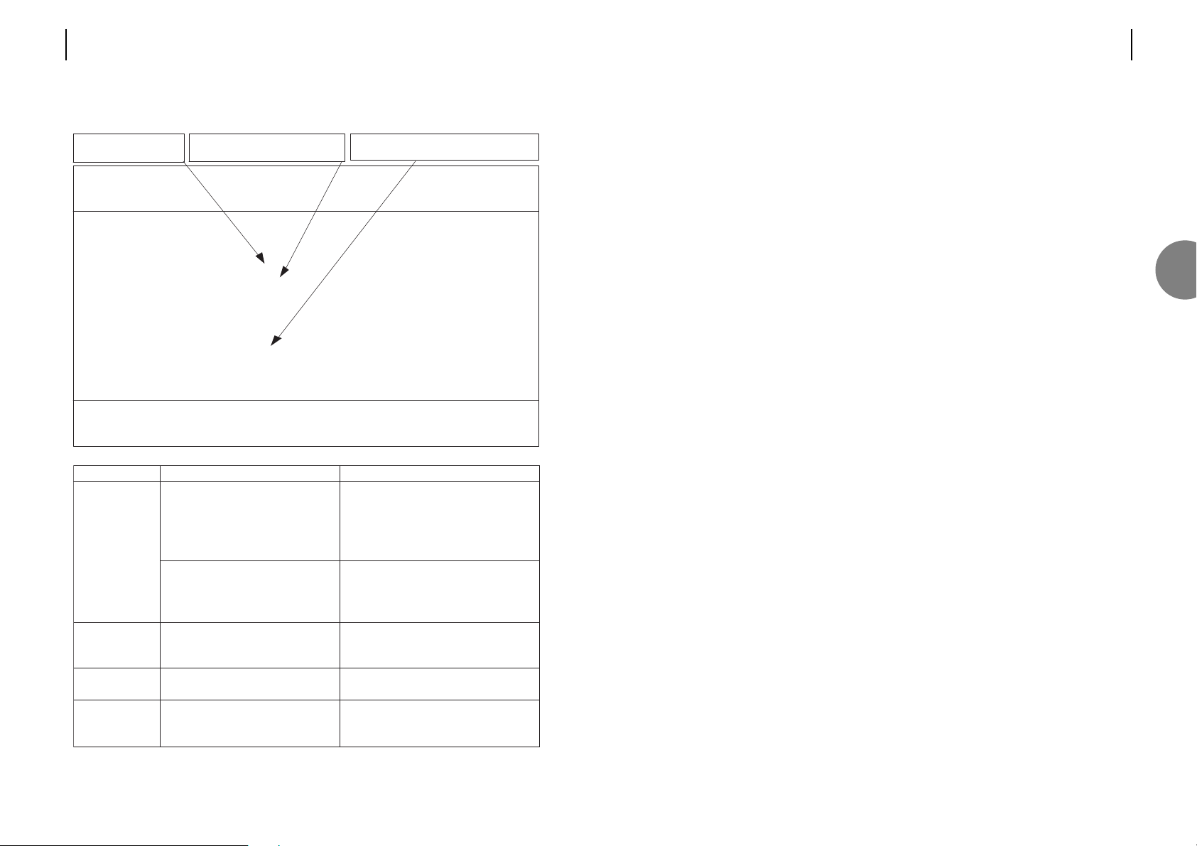
3.7 FRONT PANEL
3.7.1 Controls
The front panel controls have a dual purpose. For normal operation, the LED indicators display
status information as described in section 3.7.2 and the push buttons are used for applying
test loops as described in section 3.7.1.4. These controls can however, also be used to
configure the modems without the need to plug in a VT100 terminal or PC. To do this, the
front panel controls must be enabled for "Full Control" (default setting) and the unit set to
Programming Mode.
3.7.1.1 Disabling the Front Panel Controls
The modems are delivered with the front panel controls fully enabled as the default
configuration. This means that both test loop activation and modem programming are
possible from the front panel. They can however be disabled to prevent unauthorised persons
from using them to interfere with the settings of the modem. The VT100 management
system (which can be password protected) is used to enable or disable the front panel controls
via the Configuration > Front Panel menu (see section 7.2.10). The options available are "Full
Control" (default), "Loops Only" and "Input Disabled".
3.7.1.2 Programming Mode
To enter the programming mode, press the Local Loop and Loop Back buttons together and
then release them. Upon releasing the buttons, the Status indicator starts to flash. This
indicates that the unit is in programming mode and will continue to flash for approximately 30
seconds after the last programming action. Programming is carried out using the Local Loop
and Loop Back buttons, with the LED indicators showing the parameter numbers and their
values. The Remote Loop button is used to store the new parameter value. If the values aren't
stored within the 30 second timeout period, the modem will exit programming mode (Status
Indicator stops flashing) and the new parameter values will be discarded.
Refer to Appendix B for a full explanation on entering parameters using the front panel
3.7.1.3 Resetting to Factory Default Configuration
Press the Local Loop and Loop Back buttons together, and then with the buttons still pressed,
press the Remote Loop button as well. The unit will automatically restart with all of its
configuration data cleared.
Note: When the units reboots it will be configured as a "Slave".
ATL USER GUIDE
OM100 Optical Multiplexer
2928 ATL USER GUIDE
OM100 Optical Multiplexer
3.6.2.1 Troubleshooting - User Ports
Problem
Incoming signal is not present.
(LOS means Loss Of Signal).
Incoming signal is too small.
Alarm Indication Signal detected.
(AIS is transmitted by equipment
that have a major fault).
Small number of bit errors.
On user port.
High number of bit errors.
On user port.
Alarm
LOS detected
AIS detected
BER > 10E-6
BER > 10E-3
Cause
Cables are broken
Cables wired incorrectly
Major fault within terminal equipment
Terminal equipment not powered on
Cables are faulty
Cable of insufficient quality
Cable too long
Too many connections
Terminal equipment fault
Electrically active environment
Earth grounding problem
Cables are faulty
Cables of insufficient quality
Cables are too long
LOS indicates that no
signal is present
AIS indicates that the Terminal
equipment has a serious fault
Counters start once a signal has been
detected - initially, they remain frozen.
OM100 Mon 01 Nov 2002 00:54:49
Performance > User Port
Urgent Alarm:Off Non-Urgent Alarm:On
Subsystem: LT
Port: 1
LOS Detected [ ] BER > 1E-3 [ ]
AIS Detected [ ] BER > 1E-6 [ ]
Line Code Violations 0 Trip Counter 0
Available Seconds 100 Trip Counter 100
Unavailable Seconds 0 Trip Counter 0
Severely Errored Seconds 0 Trip Counter 0
Errored Seconds 0 Trip Counter 0
Error Free Seconds 100 Trip Counter 100
Press Escape to Exit
F1 Help F3 Previous Menu F4 Main Menu F5 Previous Channel
F6 Next Channel F7 Previous Subsystem F8 Next Subsystem F9 Reset Trips
F10 Reset System Counters
3
Page 17
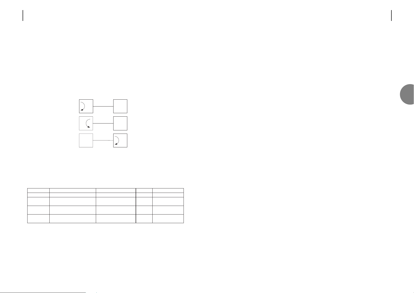
The single colour LED indicators are interpreted as follows:
Master (Green)
When lit, this LED indicates that the unit has been configured to operate as a 'master'. The
default setting is for the unit to be a 'slave', in which case the LED will be turned off.
Test (Red)
This will be illuminated whenever a loop test is active in the system. i.e. The LED will
illuminate no matter which end of the link the test is applied.
ATL USER GUIDE
OM100 Optical Multiplexer
3130 ATL USER GUIDE
OM100 Optical Multiplexer
3.7.1.4 Setting Loops
The following test loops may be set using the front panel buttons.
o Local Loop
o Loop back
o Remote Loop
Note. These buttons may be disabled from the 'Configuration > Front Panel' menu.
3.7.2 Indicators
There are seven tri-colour LEDs that provide status information. These are interpreted as
follows:
*The status LED flashes Green when the unit is in programming mode.
+
only active on OM100 1+1 SF SM units.
LED Red. Urgent Amber. Non-Urgent Green Off
Status*
System Alarm System Alarm OK Power OFF
Optical 1
Optical Alarm
e.g. LOS, High BER
Optical Alarm
e.g. Low BER
OK N/A
Optical 2
+
Optical Alarm
e.g. LOS, High BER
Optical Alarm
e.g. Low BER
OK N/A
Ch.1..4
User Port Alarm
e.g. LOS, AIS, High BER
User Port Alarm
e.g. Low BER
OK
No input signal
at user port
Local Loop
Loop back
Remote Loop
Local Unit
Remote Unit
3
Page 18

1. Connect the terminal.
2. Press the space bar.
Note: If the local terminal is connected after the unit is turned on this screen may be missed.
OOOOOOO MM MM 11 000000 000000
OOOOOOOOOOO MMM MMM 111 0000000000 0000000000
OOO OOO MMMM MMMM 11 000 000 000 000
OO OO MM MM MM MM 11 00 00 00 00
OO OO MM MMMM MM 11 00 00 00 00
OO OO MM MM MM 11 00 00 00 00
OO OO MM MM 11 00 00 00 00
OO OO MM MM 11 00 00 00 00
OOO OOO MM MM 11 000 000 000 000
OOOOOOOOOOO MM MM 11 0000000000 0000000000
OOOOOOO MM MM 1111 000000 000000
Login (Configuration, Test, Read-Only):
OOOOOOO MM MM 11 000000 000000
OOOOOOOOOOO MMM MMM 111 0000000000 0000000000
OOO OOO MMMM MMMM 11 000 000 000 000
OO OO MM MM MM MM 11 00 00 00 00
OO OO MM MMMM MM 11 00 00 00 00
OO OO MM MM MM 11 00 00 00 00
OO OO MM MM 11 00 00 00 00
OO OO MM MM 11 00 00 00 00
OOO OOO MM MM 11 000 000 000 000
OOOOOOOOOOO MM MM 11 0000000000 0000000000
OOOOOOO MM MM 1111 000000 000000
Press space-bar to continue
4 LOGON PROCEDURE
ATL USER GUIDE
OM100 Optical Multiplexer
3332 ATL USER GUIDE
OM100 Optical Multiplexer
4
Page 19

5. Press <y> to skip this screen next time you logon. Otherwise press <N>
OM100 Mon 01 Nov 2002 00:25:18
Main Menu
Urgent Alarm:On Non-Urgent Alarm:Off
A Alarms
C Configuration
I Information
L Logout
P Performance
S Security
T Test
Type selection:
F1 Help
Operating Instructions
[ ] = checkbox, use SPACEBAR to toggle its state.
( ) = radiobutton, use SPACEBAR to turn it on.
< > = editfield, type using characters appropriate to that field.
Use TAB and arrow keys to move around the screen.
If function keys F1-F10 not supported then use cntrl 'F' followed by 1-9 & 0.
Hide this message next time you login y/N ?
ATL USER GUIDE
OM100 Optical Multiplexer
3534 ATL USER GUIDE
OM100 Optical Multiplexer
3. Select the desired mode.
Press <C> then <return> for Configuration mode.
Press <T> then <return> for Test mode.
Or press <R> then <return> for Read-only mode.
4. Enter the password and then press <return>.
OOOOOOO MM MM 11 000000 000000
OOOOOOOOOOO MMM MMM 111 0000000000 0000000000
OOO OOO MMMM MMMM 11 000 000 000 000
OO OO MM MM MM MM 11 00 00 00 00
OO OO MM MMMM MM 11 00 00 00 00
OO OO MM MM MM 11 00 00 00 00
OO OO MM MM 11 00 00 00 00
OO OO MM MM 11 00 00 00 00
OOO OOO MM MM 11 000 000 000 000
OOOOOOOOOOO MM MM 11 0000000000 0000000000
OOOOOOO MM MM 1111 000000 000000
Login (Configuration, Test, Read-Only): *
Password:********
OOOOOOO MM MM 11 000000 000000
OOOOOOOOOOO MMM MMM 111 0000000000 0000000000
OOO OOO MMMM MMMM 11 000 000 000 000
OO OO MM MM MM MM 11 00 00 00 00
OO OO MM MMMM MM 11 00 00 00 00
OO OO MM MM MM 11 00 00 00 00
OO OO MM MM 11 00 00 00 00
OO OO MM MM 11 00 00 00 00
OOO OOO MM MM 11 000 000 000 000
OOOOOOOOOOO MM MM 11 0000000000 0000000000
OOOOOOO MM MM 1111 000000 000000
Login (Configuration, Test, Read-Only): *
Password:
4
Page 20

1. Press F4 from any menu. This jumps to the top level menu.
2. Press <L> to initiate the logout.
3. Press <y> to finalise the logout.
Note: If monitoring mode is ON this screen will now display alarms as they are generated.
Otherwise it will go back to the very first logon screen, after a short delay.
Monitoring Mode is off.
OM100 Mon 01 Nov 2002 00:51:16
Main Menu
Urgent Alarm:Off Non-Urgent Alarm:On
A Alarms
C Configuration
I Information
L Logout
P Performance
S Security
T Test
Type selection:L
Are you sure ? (y/N)
5 LOGOFF PROCEDURE
ATL USER GUIDE
OM100 Optical Multiplexer
3736 ATL USER GUIDE
OM100 Optical Multiplexer
5
Page 21

There are 3 types of menu screens; navigation screens that guide the user down through the
menu topology, configuration screens that allow the user to turn functions ON and OFF, and
information screens that provide information on the status of the unit.
6.1 NAVIGATION SCREENS
Pressing the appropriate key activates its associated menu. There is no need to press <return>
(In fact pressing <return> will, in most cases, have the undesired effect of exiting the selected
screen).
Functions keys change as you change screens
Screen name Time and date
OM100 Mon 01 Nov 2002 00:38:20
Configuration Menu
Urgent Alarm:On Non-Urgent Alarm:Off
M Master/Slave
U User Port
P Protection Switching
R Reboot
S System
N Subsystem Names
O Monitoring
W Software
C Serial Communications
F Front Panel
Type selection: M
F1 Help F3 Previous Menu F4 Main Menu
6 MENU SCREEN
ATL USER GUIDE
OM100 Optical Multiplexer
3938 ATL USER GUIDE
OM100 Optical Multiplexer
6
Page 22
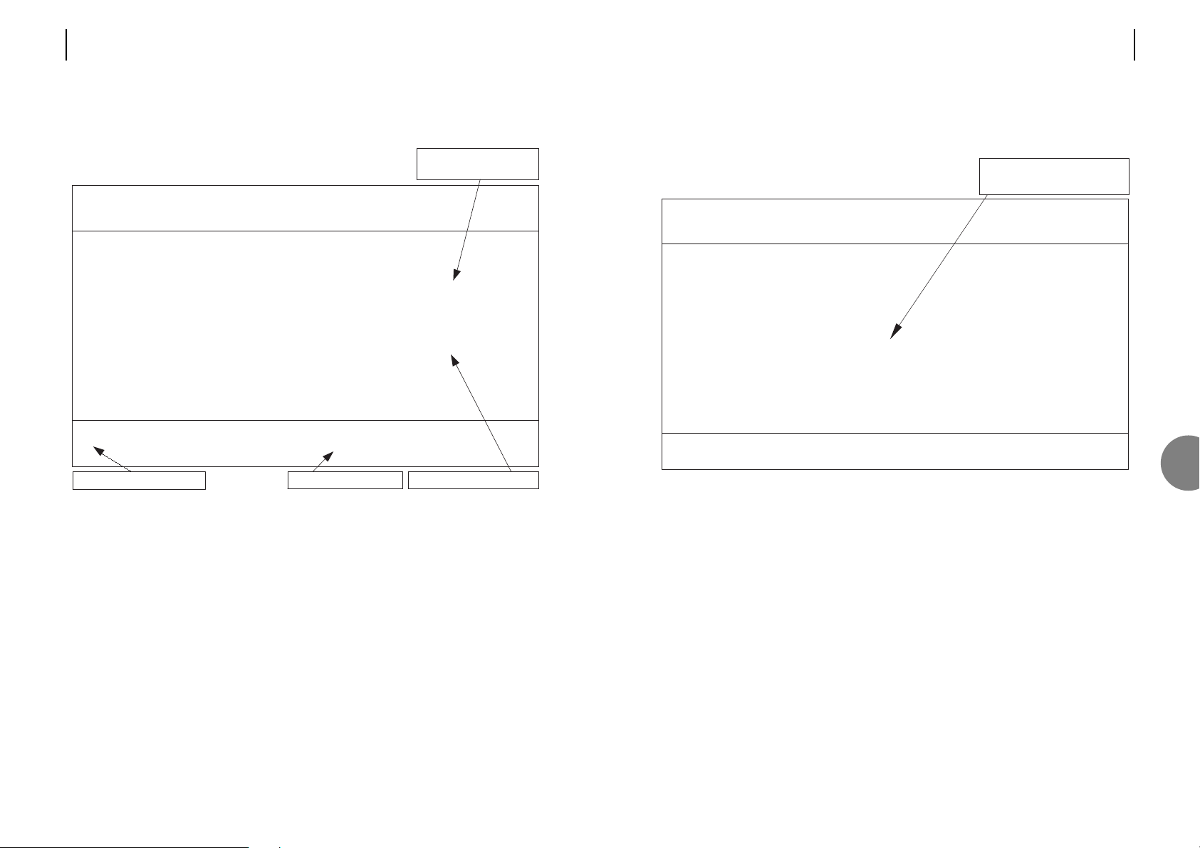
6.3 CONFIGURATION SCREENS
6.3.1 Entering data
6.3.2 Moving between check boxes
Select check boxes and radio buttons in the same way.
Pressing either the right cursor key, or the <TAB> key cycles through the check boxes. Use the
left cursor, or <BACK TAB> key to cycle backwards.
6.3.3 Turning functions on and off
Find the appropriate check box associated with the function you want to change. Move the
cursor to that check box. Then press the space bar to change the box. Repeat for all other
required changes. Press the <return> key to accept the configuration.
Note: The configuration is not accepted until the <return> key is pressed. In this way mistakes
can be corrected before the data is entered. Beware though, if you exit the screen before
pressing <return> the changes will be cancelled. Pressing the <return> key makes the changes
and exits the screen, so you may want to make more than one change to the screen before
pressing the <return> key.
OM100 Mon 01 Nov 2002 00:34:32
Config > User Ports
Urgent Alarm:On Non-Urgent Alarm:Off
Subsystem: LT
Lock Clock
Enable to Reference
Port 1 [X]
Port 2 [X] [ ]
Port 3 [X] [ ]
Port 4 [X] [ ]
Press Return to Accept or Escape to Cancel
F1 Help F3 Previous Menu F4 Main Menu
Check boxes turn functions
ON and OFF.
ATL USER GUIDE
OM100 Optical Multiplexer
4140 ATL USER GUIDE
OM100 Optical Multiplexer
6.2 INFORMATION SCREENS
These screens provide version, alarm and performance information about the system. They are
particularly useful in helping locate problems with any of the ports.
A master unit can view information about itself and about the remotely connected slave unit. A
slave unit can only view it’s local information.
[X] indicates that the
alarm detector is active
Trip counters can be reset
View the remote unit
View next port statistics
OM100 Mon 01 Nov 2002 00:54:49
Performance > User Port
Urgent Alarm:Off Non-Urgent Alarm:On
Subsystem: LT
Port: 1
LOS Detected [ ] BER > 1E-3 [x]
AIS Detected [ ] BER > 1E-6 [ ]
Line Code Violations 0 Trip Counter 0
Available Seconds 100 Trip Counter 100
Unavailable Seconds 0 Trip Counter 0
Severely Errored Seconds 0 Trip Counter 0
Errored Seconds 0 Trip Counter 0
Error Free Seconds 100 Trip Counter 100
Press Escape to Exit
F1 Help F3 Previous Menu F4 Main Menu F5 Previous Channel
F6 Next Channel F7 Previous Subsystem F8 Next Subsystem F9 Reset Trips
F10 Reset System Counters
6
Page 23
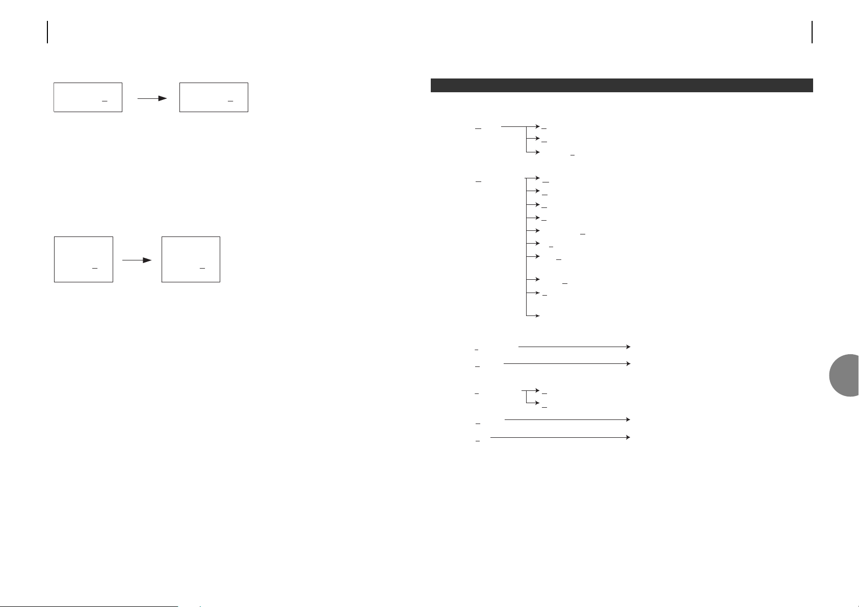
Top level Sub level Description
Alarms Status Displays the current alarm status.
History Review the fault log. View recorded alarm events.
Severity Level Settings Set fault level. Configure Urgent & Non urgent
alarm sources.
Configuration Master / Slave Master / slave configuration.
User Port Configure each E1 port – enable.
Protection Switching Configures the 1+1 protection switching.
System Set date, time and menu timeout.
Subsystem Names Enter name, description and location of this unit.
Monitoring Mode Configures monitoring mode.
Software Allows the downloading of software to the unit
and allows reset to factory default.
Serial Communications Local terminal set-up – baud rate, parity, handshake.
Reboot This option allows you to reboot the unit that you
are using, as well as its remote partner.
Front Panel Allows configuration of Front Panel controls.
Information Displays the designation of the unit.
Logout Logout of the menus and enter
monitoring mode.
Performance Optical Transmission Line Counter and status indicators for the optical lines.
User Port Counter and status indicators for the user ports.
Security Change passwords.
Test Enables various loopbacks.
7 MENU TOPOLOGY
ATL USER GUIDE
OM100 Optical Multiplexer
43
7
42 ATL USER GUIDE
OM100 Optical Multiplexer
For example: To disable a port – move the cursor to the check box, press the space bar and
then press <return>.
6.3.4 How radio buttons work
These are multiple choice check boxes. Only one can be active (mutually exclusive).
In this example “Parity” can be set to one of three possible options; None, Odd, or Even.
It would not make sense to set it to be both Odd and Even at the same time, so we only
allow one of the three options to be set.
To change the Parity from NONE to ODD – move the cursor to the ODD box, and press the
space bar. Remembering to press <return>, once any other changes have been made.
Parity
None (*)
Odd ( )
Even ( )
Parity
None ( )
Odd (*)
Even ( )
Enable [X]
Enable [ ]
Page 24
44 ATL USER GUIDE
OM100 Optical Multiplexer
7.1 ALARMS
7.1.1 Alarm status screen
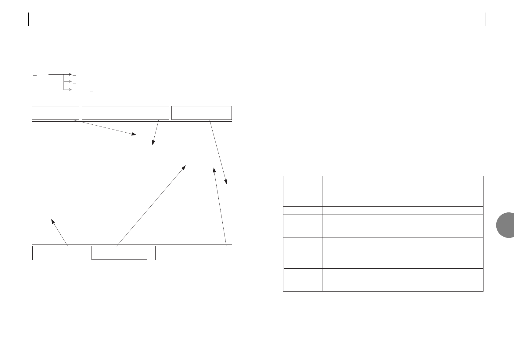
F5 Clear
To remove an alarm from the list. Use the cursors to highlight it. Then press F5 to clear the
line. Only inactive alarms (marked ‘OFF’) can be removed from the list.
F6 Acknowledge
To acknowledge an alarm. Use the cursors to highlight it. Press F6 to acknowledge the alarm.
OM100 Mon 01 Nov 2002 00:45:50
Alarm > Status
Urgent Alarm:Off Non-Urgent Alarm:On Test Active
Display Filters: Level 1[ ] 2[X] 3[X] 4[X] 5[X] Status=Off/Update[X]
No.| Subsystem | Alarm Description | Level | Status |A
001|LT |Optical Port 1 - LOS | 5 | Off |
002|LT |User Port 2 - BER > 1E-3 | 3 | On |
003|LT |User Port 3 - BER > 1E-3 | 3 | On |
004|LT |User Port 4 - BER > 1E-3 | 3 | On |
005|LT |User Port 1 - BER > 1E-3 | 3 | On |A
006|NTu |User Port 1 - BER > 1E-3 | 3 | On |
007|NTu |User Port 2 - BER > 1E-3 | 3 | On |
008|NTu |User Port 3 - BER > 1E-3 | 3 | On |
009|NTu |User Port 4 - BER > 1E-3 | 3 | On |
010|NTu |Test Active | 2 | On |
Press Escape to Exit
F1 Help F2 History F3 Previous Menu F4 Main Menu F5 Clear
F6 Acknowledge F7 Previous Page F8 Next Page F10 Update
Non - Urgent alarm
is active
10 alarms logged.
Not all currently active.
Display filter hides alarms not of interest.
Only alarm levels marked [x] are shown.
'User Port 1' has been
acknowledged (muted)
'Optical Port 1 - LOS' alarm has
been active, but is currently inactive
Level 4&5 alarms activate
the URGENT alarm
Alarms Status Displays the current alarm status.
History Review the fault log. View recorded alarm events.
Severity Level Settings Set fault level. Configure Urgent & Non urgent
alarm sources.
ATL USER GUIDE
OM100 Optical Multiplexer
45
Acknowledged alarms are muted, i.e. they generate neither URGENT or Non-URGENT alarms.
To clear the acknowledgement, fix the fault then clear (F5) the alarm.
F10 Update
This screen is set to automatically update by default. However if the Status = Off/Update field
has been set to off, it may be necessary to update this screen manually by pressing F10.
Display Filters: Level 1 [ ] 2 [ ] 3 [ ] 4 [X] 5 [X]
If many alarms are active the user may wish to concentrate on investigating the higher priority
alarms first. To show alarms, select the appropriate display filter boxes with ‘X’, however,
hidden alarms will still generate Urgent and Non-urgent alarms.
Status = Off/Update [X]
To turn off automatic updates of this screen. Use the cursors to select the Status = Off/Update
[X] field. Pressing the space bar toggles the setting. The screen will not update until manually
refreshed – press F10 to manually update.
Description
Each entry is given a number.
Identifies which unit the alarm occurred on. The name is configured in the
Configuration->Subsystem name screen.
Refer to Section 7.1.3.2 for description of the various alarms.
Shows the alarm severity. Configure in Alarms->Severity Level Settings.
1=Record in fault log only, 2&3=Active Non-Urgent alarm, 4&5=Active
Urgent alarm.
ON = alarm currently active.
OFF = Transient alarm. Alarm is currently inactive, but has previously
been active.
Press F5 to clear.
Indicates that the alarm has been acknowledged, this mutes the alarm source.
Once an alarm has been acknowledged it can no longer generate either the
Urgent or Non-urgent alarm.
Field
No.
Subsystem
Alarm description
Level
Status
A
7
Page 25
ATL USER GUIDE
OM100 Optical Multiplexer
47
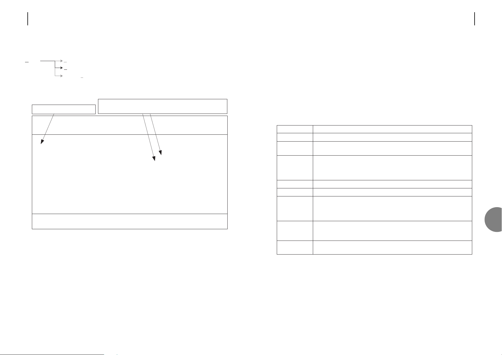
F5 Clear History
Removes ALL entries from the fault log.
F9 Dump
Produces a continual listing of the fault log. Useful when capturing to a file.
F10 Update
The screen is not updated in real time. Events that occur after first entering the screen are not
displayed. To manually update the screen with recent events, press F10.
Description
Each entry is given a number.
Identifies which unit the alarm occurred on. The name is configured in the
Configuration->Subsystem name screen.
Refer to Section 7.1.3.2 for description of the various alarms.
The 'ON' suffix indicates the recorded time and date the alarm went active.
OFF indicates when the alarm became inactive.
Records the exact time the event occurred.
Records the date the event occurred.
Indicated that the alarm has been acknowledged, this mutes the alarm source.
Once an alarm has been acknowledged it can no longer generate the Urgent
or Non-urgent alarm.
This checkbox controls the display of alarms that have been acknowledged in
the Alarm Screen. An 'A' in the 'A' (acknowledge) column indicates
acknowledged alarms.
This checkbox enables the display of only those events on the same subsystem
as the currently highlighted alarm entry.
Field
No.
Subsystem
Fault description
Time
Date
A
Display Ack'd.
Faults [X]
Subsystem [ ]
7
46 ATL USER GUIDE
OM100 Optical Multiplexer
7.1.2 Alarm history screen
This screen is used to view the last 250 alarms recorded by the system. If there is more than
one screen's worth of information, the up and down arrow keys may be used to scroll
through the list.
The Master will report all of its alarms and those of its connected Slave unit.
To scroll between checkboxes, use the left and right cursor keys.
To scroll between the alarm entries, use the up and down cursor keys.
F2 Show Id/Name
Toggles the ‘subsystem’ display field between name and ID.
'Optical Port 1' alarm went active at midnight on the 17th of
February 2002, and went inactive 45 minutes later
10 alarm events have occurred
OM100 Mon 01 Nov 2002 00:46:28
Alarm > History
Urgent Alarm:Off Non-Urgent Alarm:On
Display Acknowledged Faults [X] Subsystem [ ]
No.| Subsystem | Fault Description | Time | Date |A
001|LT |Cold Boot |00:00:01|17/02/2002|
002|LT |Optical Port 1 - LOS ON|00:00:02|17/02/2002|
003|LT |Optical Port 1 - LOS OFF|00:45:18|17/02/2002|
004|LT |User Port 2 - BER > 1E-3 ON|00:45:18|17/02/2002|
005|LT |User Port 3 - BER > 1E-3 ON|00:45:18|17/02/2002|
006|LT |User Port 4 - BER > 1E-3 ON|00:45:18|17/02/2002|
007|LT |User Port 1 - BER > 1E-3 ON|00:45:18|17/02/2002|
008|NTu |User Port 1 - BER > 1E-3 ON|00:45:26|17/02/2002|
009|NTu |User Port 2 - BER > 1E-3 ON|00:45:27|17/02/2002|
010|NTu |User Port 3 - BER > 1E-3 ON|00:45:27|17/02/2002|
Press Escape to Exit
F1 Help F2 Show Id/Name F3 Previous Menu F4 Main Menu F5 Clear History
F7 Previous Page F8 Next Page F9 Dump F10 Update
Alarms Status Displays the current alarm status.
History Review the fault log. View recorded alarm events.
Severity Level Settings Set fault level. Configure Urgent & Non urgent
alarm sources.
Page 26
ATL USER GUIDE
OM100 Optical Multiplexer
49
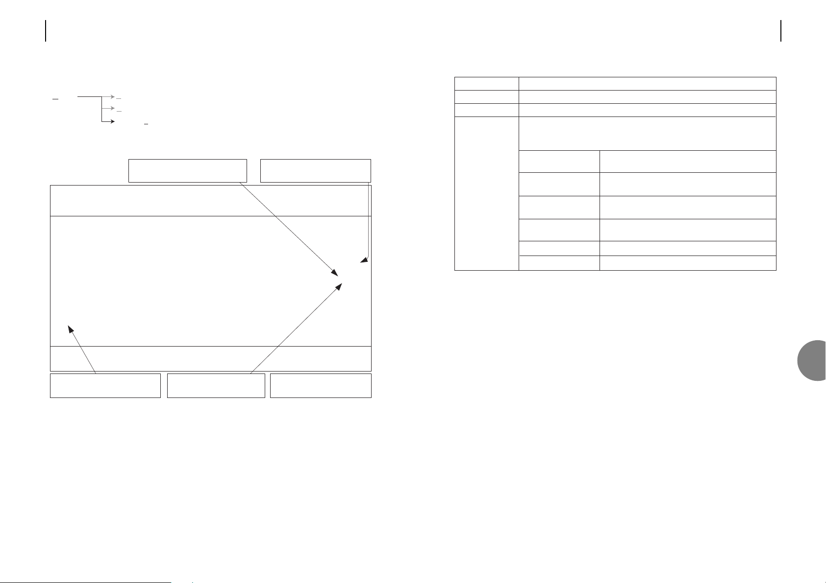
Description
Each alarm is given a unique number.
Refer to Section 7.1.3.2 for description of the various alarms.
The severity level for each alarm is configurable.
Alarms can be filtered in the alarm screen based on severity level.
The non-urgent and urgent alarms are based on this severity level.
5 (highest priority) Generate the URGENT alarm.
Fault recorded in the fault log.
4 Generate the URGENT alarm.
Fault recorded in the fault log.
3 Generate the Non-URGENT alarm.
Fault recorded in the fault log.
2 Generate the Non-URGENT alarm.
Fault recorded in the fault log.
1 Fault recorded in the fault log.
0 (lowest priority) Alarm disabled. Not logged or displayed.
Field
Id
Fault description
level
7
48 ATL USER GUIDE
OM100 Optical Multiplexer
7.1.3 Alarm severity level settings
F5 Default
To restore the default alarm severity level to an alarm – use the cursors to highlight the desired
line, then press F5 to restore its default alarm severity level.
OM100 Mon 01 Nov 2002 00:47:28
Alarm > Severity Level Settings
Urgent Alarm:Off Non-Urgent Alarm:On
Id| Fault Description | Level
001|Cold Boot <1>
002|Warm Boot <1>
003|Failed to program (Fault:%n) <1>
004|Power Fail <5>
005|Security - password rejected <1>
006|Test Active <1>
007|H/W - Configuration Memory Fail <5>
008|H/W - FPGA Configuration Fail <5>
009|Optical Port %n - LOS <5>
010|Optical Port %n - Laser Fault <3>
Press Return to Accept or Escape to Cancel
F1 Help F3 Previous Menu F4 Main Menu F5 Default F7 Previous Page
F8 Next Page
Alarm severity can be individually
programmed for every alarm
Levels 4&5 alarms activate the
URGENT alarm
Levels 2&3 alarms activate
the Non-URGENT alarm
Level 1 alarms are only
recorded in the fault log
Id's 11 to 20 are on screen 2.
Press F8 to scroll down.
Alarms Status Displays the current alarm status.
History Review the fault log. View recorded alarm events.
Severity Level Settings Set fault level. Configure Urgent & Non urgent
alarm sources.
Page 27

ATL USER GUIDE
OM100 Optical Multiplexer
51
7.2 CONFIGURATION
7.2.1 Master/Slave configuration
In order for a pair of units to operate correctly, one end must be set as a master, the other end
as a slave. Normally the unit connected to the customer will be configured as a slave.
OM100 Mon 01 Nov 2002 00:40:26
Configuration > Master/Slave Operation
Urgent Alarm:On Non-Urgent Alarm:Off
Master (*)
Slave ( )
Saving changes to this screen will cause unit to reboot
Press Return to Accept or Escape to Cancel
F1 Help F3 Previous Menu F4 Main Menu
Configuration Master / Slave Master / slave configuration.
User Port Configure each E1 port – enable.
Protection Switching Configures the protection 1+1 switching.
System Set date, time and menu timeout.
Subsystem Names Enter name, description and location of this unit.
Monitoring Mode Configures monitoring mode.
Software Allows the downloading of software to the unit
and allows reset to factory default.
Serial Communications Local terminal set-up – baud rate, parity, handshake.
Reboot This option allows you to reboot the unit that you
are using, as well as its remote partner.
Front Panel Allows configuration of Front Panel controls.
7
50 ATL USER GUIDE
OM100 Optical Multiplexer
7.1.3.2 Alarm sources
*Where n = 1..4 and m = 1..2
Definition
Restart activated by power failure.
Restart activated by the software.
AIS detected on user port (applies to each of the 4 ports).
LOS detected on user port (applies to each of the 4 ports).
High bit error rate on user port (applies to each of the 4 ports).
Low bit error rate on user port (applies to each of the 4 ports).
Failed logon attempt.
Error whilst retrieving stored configuration.
Internal fault
Internal fault
Sync loss detected on optical port (applies to each optical port).
High bit error rate on optical port (applies to each optical port)
Low bit error rate on optical port (applies to each optical port)
Fault detected on the optical transmitter (applies to each optical port)
APS has switched to the backup link
Loopback, or test mode active
Fault description
Cold Boot
Warm Boot
User Port n* AIS
User Port n* LOS
User Port n*
BER > 1E3
User Port n
BER > 1E6
Security –
password rejected
H/W – Configuration
Memory Fail
H/W – FPGA
Configuration Fail
Failed to program
(Fault:%n)
Optical Port LOS
Optical Port m*
BER > 1E-3
Optical Port m*
BER > 1E-6
Optical Port m*
Laser Fault
Optical Port –
Backup Link Active
Test active
Page 28
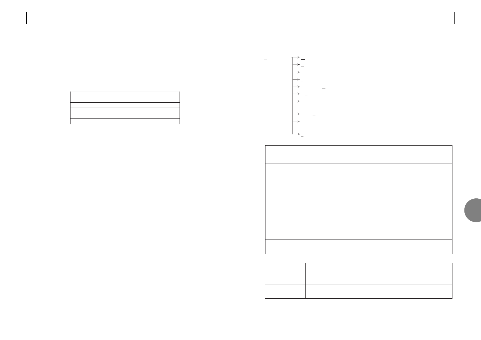
The master unit is in charge of managing the optical link, it is also the 'master' from a
network management point of view. It contains the database of configuration information for
itself and the slave unit. The alarm and performance monitoring history is saved at the master.
When the management terminal is connected to the master it can read all of the information
from the local and remote units, whereas when the management terminal is connected to the
slave, only the local information is obtainable.
* Note: Master/Slave settings are fixed for these units and cannot be altered, and a message
indicating this will be displayed for single fibre units.
It is possible to set Master/Slave by using the front panel buttons if a terminal is unavailable,
see Appendix B.
Unit Default Settings
OM100 DF DM Slave
OM100 DF SM Slave
OM100 SF SM Master Master*
OM100 SF SM Slave Slave*
OM100 1+1 SF SM Slave
ATL USER GUIDE
OM100 Optical Multiplexer
5352 ATL USER GUIDE
OM100 Optical Multiplexer
7.2.2 User port configuration
Description
Turns this user port ON, or OFF.
When OFF all traffic on this port is blocked and is replaced with AIS.
When off (default) port timing is independant of other ports.
When on the port operates in SDH mode - refer to section 3.6.2.
Field
Enable
Lock Clock to
Reference
OM100 Mon 01 Nov 2002 00:34:32
Config > User Ports
Urgent Alarm:On Non-Urgent Alarm:Off
Subsystem: LT
Lock Clock
Enable to Reference
Port 1 [X]
Port 2 [X] [ ]
Port 3 [X] [ ]
Port 4 [X] [ ]
Press Return to Accept or Escape to Cancel
F1 Help F3 Previous Menu F4 Main Menu
Configuration Master / Slave Master / slave configuration.
User Port Configure each E1 port – enable.
Protection Switching Configures the protection 1+1 switching.
System Set date, time and menu timeout.
Subsystem Names Enter name, description and location of this unit.
Monitoring Mode Configures monitoring mode.
Software Allows the downloading of software to the unit
and allows reset to factory default.
Serial Communications Local terminal set-up – baud rate, parity, handshake.
Reboot This option allows you to reboot the unit that you
are using, as well as its remote partner.
Front Panel Allows configuration of Front Panel controls.
7
Page 29
ATL USER GUIDE
OM100 Optical Multiplexer
55
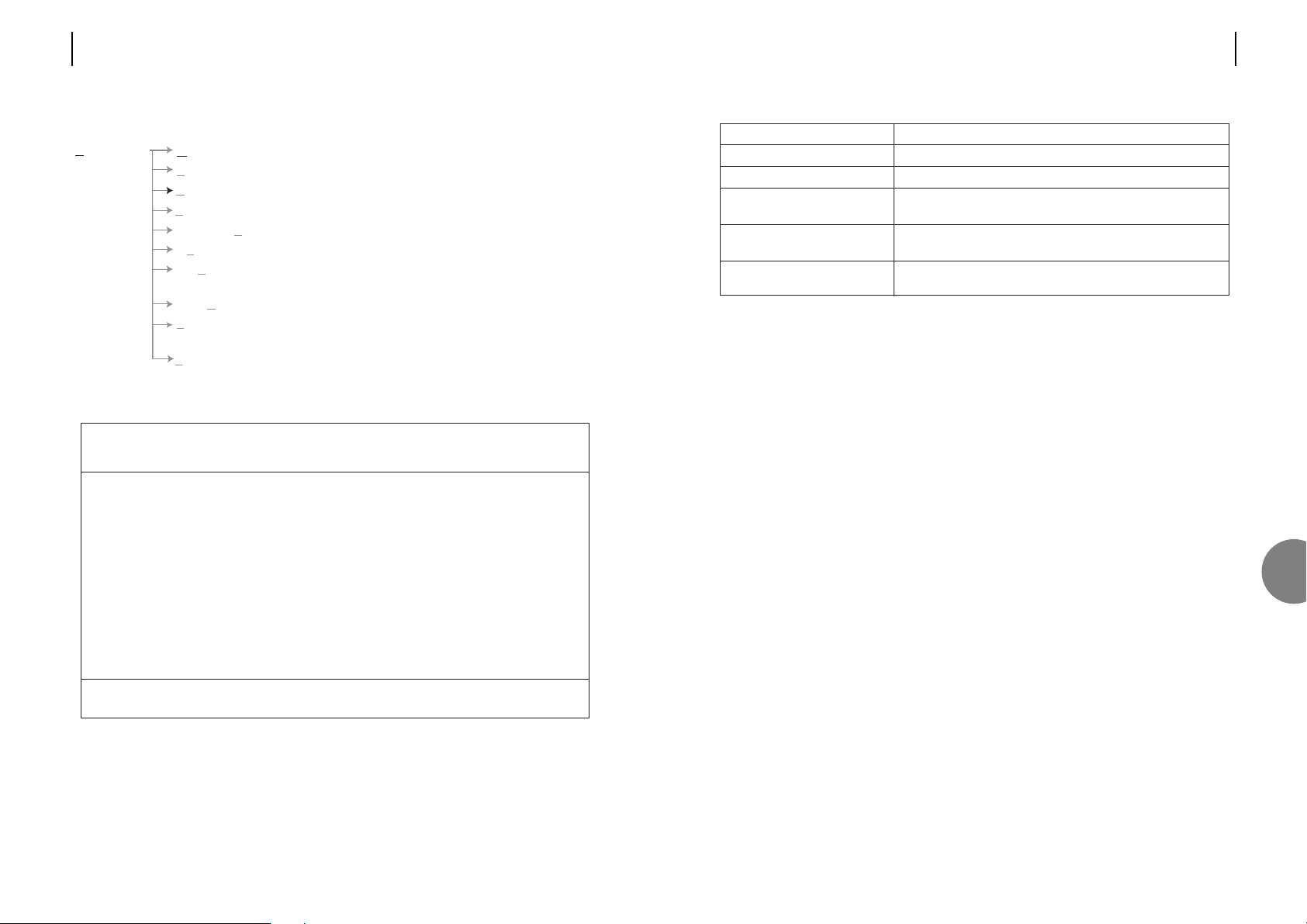
Note: This option is only available on OM100 1+1 SFSM units.
Description
Turns on/off the 1+1 protection switching.
Switch to another link upon detection of LOS
Switch to another optical link upon detection of high bit error
rate exceeding 1x10E-3
The unit will perform a switch if the error rate on the optical
link within any 15 minute period exceeds 1x10E-7.
The unit will perform a switch if the error rate on the optical
link within any 24 hour period exceeds 1x10E-9.
Field
Enable
Switch on LOS
Switch on BER > 10E-3
Switch On Medium Term
Errors > 10E-7
Switch On Long Term Errors >
10E-9
7
54 ATL USER GUIDE
OM100 Optical Multiplexer
7.2.3 Protection switching configuration
OM100 Mon 01 Nov 2002 00:41:29
Config > Protection Switching
Urgent Alarm:On Non-Urgent Alarm:Off
Enable [ ]
Switch On LOS [ ]
Switch On BER > 10E-3 [ ]
Switch On Bad Medium Term Errors > 10E-7 [ ]
Switch On Bad Long Term Errors > 10E-9 [ ]
Press Return to Accept or Escape to Cancel
F1 Help F3 Previous Menu F4 Main Menu
Configuration Master / Slave Master / slave configuration.
User Port Configure each E1 port – enable.
Protection Switching Configures the 1+1 protection switching.
System Set date, time and menu timeout.
Subsystem Names Enter name, description and location of this unit.
Monitoring Mode Configures monitoring mode.
Software Allows the downloading of software to the unit
and allows reset to factory default.
Serial Communications Local terminal set-up – baud rate, parity, handshake.
Reboot This option allows you to reboot the unit that you
are using, as well as its remote partner.
Front Panel Allows configuration of Front Panel controls.
Page 30
ATL USER GUIDE
OM100 Optical Multiplexer
57
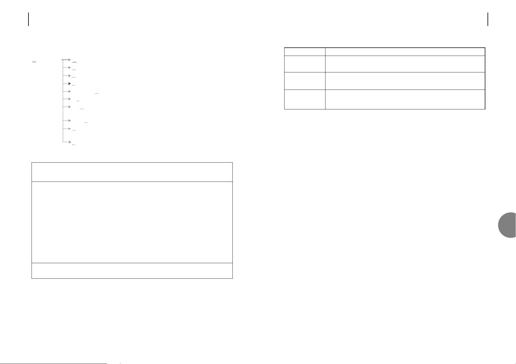
Notes: a) The time and date are changed at the exact moment the <return> key is pressed.
b) Setting the “Inactive Time-Out”, should be done only after the time and date has
been set.
Description
Enter the new date in the format shown below.
dd/mm/yyyy.
Enter the new time in the format shown below.
hh:mm.
If the unit is left unattended the menus will automatically time-out.
The lower level menus will jump back one level. The top level menu will log
the user out. Pressing keys resets the time-out period.
Field
Date
Time
Inactive Time-Out
7
56 ATL USER GUIDE
OM100 Optical Multiplexer
7.2.4 Date and time set-up
OM100 Mon 01 Nov 2002 00:41:51
Configuration > System
Urgent Alarm:On Non-Urgent Alarm:Off
Date <01/11/2002>
Time (24Hr) <00:41>
Inactive Time-Out (min) <30>
Press Return to Accept or Escape to Cancel
F1 Help F3 Previous Menu F4 Main Menu
Configuration Master / Slave Master / slave configuration.
User Port Configure each E1 port – enable.
Protection Switching Configures the protection 1+1 switching.
System Set date, time and menu timeout.
Subsystem Names Enter name, description and location of this unit.
Monitoring Mode Configures monitoring mode.
Software Allows the downloading of software to the unit
and allows reset to factory default.
Serial Communications Local terminal set-up – baud rate, parity, handshake.
Reboot This option allows you to reboot the unit that you
are using, as well as its remote partner.
Front Panel Allows configuration of Front Panel controls.
Page 31
7.2.6 Monitoring mode
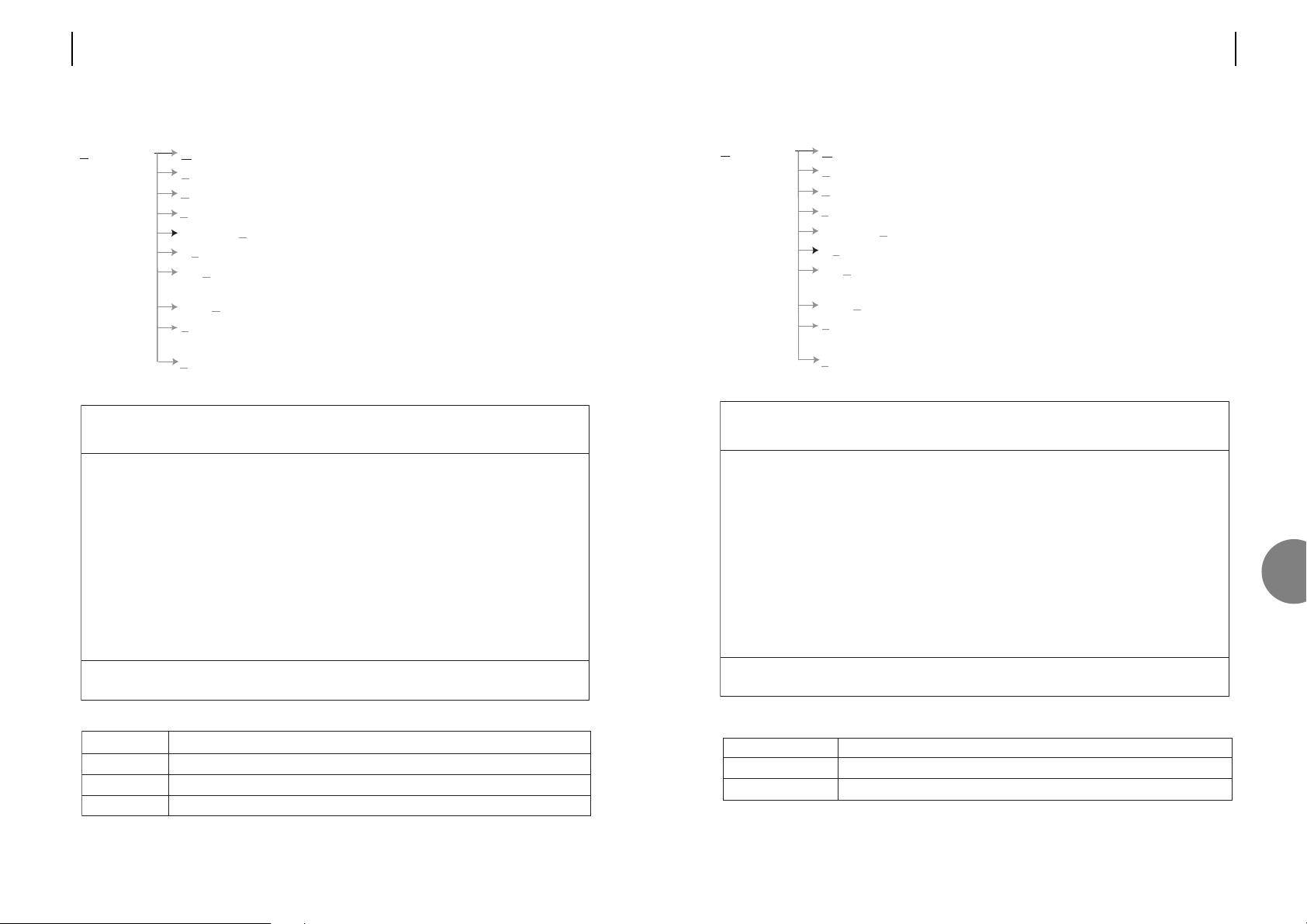
Field Description
Report faults When logged off – prints alarms and faults as they occur
With warning bell Rings the bell each time a new fault is detected
OM100 Mon 01 Nov 2002 00:42:40
Configuration > Monitoring
Urgent Alarm:On Non-Urgent Alarm:Off
Monitoring Mode
Report Faults [ ]
With Warning Bell [ ]
Press Return to Accept or Escape to Cancel
F1 Help F3 Previous Menu F4 Main Menu
Configuration Master / Slave Master / slave configuration.
User Port Configure each E1 port – enable.
Protection Switching Configures the protection 1+1 switching.
System Set date, time and menu timeout.
Subsystem Names Enter name, description and location of this unit.
Monitoring Mode Configures monitoring mode.
Software Allows the downloading of software to the unit
and allows reset to factory default.
Serial Communications Local terminal set-up – baud rate, parity, handshake.
Reboot This option allows you to reboot the unit that you
are using, as well as its remote partner.
Front Panel Allows configuration of Front Panel controls.
7
ATL USER GUIDE
OM100 Optical Multiplexer
5958 ATL USER GUIDE
OM100 Optical Multiplexer
7.2.5 Subsystem names
Field Description
Name 10 characters displayed on most menus - Used to identify the unit.
Description Text field. For information only.
Location Text field. For information only.
OM100 Mon 01 Nov 2002 00:42:19
Configuration > Subsystem Names
Urgent Alarm:On Non-Urgent Alarm:Off
Subsystem No: 1
Name <LT >
Description <Undefined >
Location <Undefined >
Press Return to Accept or Escape to Cancel
F1 Help F3 Previous Menu F4 Main Menu F7 Previous Subsystem
F8 Next Subsystem
Configuration Master / Slave Master / slave configuration.
User Port Configure each E1 port – enable.
Protection Switching Configures the protection 1+1 switching.
System Set date, time and menu timeout.
Subsystem Names Enter name, description and location of this unit.
Monitoring Mode Configures monitoring mode.
Software Allows the downloading of software to the unit
and allows reset to factory default.
Serial Communications Local terminal set-up – baud rate, parity, handshake.
Reboot This option allows you to reboot the unit that you
are using, as well as its remote partner.
Front Panel Allows configuration of Front Panel controls.
Page 32

7.2.7 Download
Field Description
Load This allows the downloading of software onto the unit.
Default When the Subsystems load option is selected, this option will only take effect after
Config. successful completion of the code download. This option may be required if a new
version of software has new configuration parameters.
OM100 Mon 01 Nov 2002 00:43:13
Configuration > Software
Urgent Alarm:On Non-Urgent Alarm:Off
WARNING!
Powering down during a download may cause units to operate incorrectly!
Subsystems Load Default Config
LT [ ] [ ]
NTu [ ] [ ]
Press Return to Accept or Escape to Cancel
F1 Help F2 System Information F3 Previous Menu F4 Main Menu
Configuration Master / Slave Master / slave configuration.
User Port Configure each E1 port – enable.
Protection Switching Configures the protection 1+1 switching.
System Set date, time and menu timeout.
Subsystem Names Enter name, description and location of this unit.
Monitoring Mode Configures monitoring mode.
Software Allows the downloading of software to the unit
and allows reset to factory default.
Serial Communications Local terminal set-up – baud rate, parity, handshake.
Reboot This option allows you to reboot the unit that you
are using, as well as its remote partner.
Front Panel Allows configuration of Front Panel controls.
ATL USER GUIDE
OM100 Optical Multiplexer
6160 ATL USER GUIDE
OM100 Optical Multiplexer
This screen is concerned with the monitoring mode of the master or slave units. This facility
causes system faults to be reported to a dumb terminal or printer whilst the operator is logged
out.
Monitoring mode is a special mode that can operate when the user has logged off. It is
designed to connect to a printer or an unattended terminal. As alarms and faults are detected
they are printed on the screen (one line per fault). Over time a complete list of faults will
be seen.
Should the VT100 terminal remain connected whilst logged out, and provided that certain
options (in the Configuration > Monitoring Screen) have been set, warning messages
indicating alarm conditions will be displayed. These warning messages may be accompanied
by an audible beep.
The VT100 terminal may at this point be replaced by a printer with a serial interface, allowing
hard copy of all alarms to be obtained.
It is envisaged that a dumb terminal may be left continuously connected to the master or slave
after the operator has logged out. This mode may then be used to register the indication of
alarms externally. The dumb terminal may be used to report alarm situations. These external
indications would consist of warning messages and/or alarm bells.
Format of warnings displayed in Monitor Mode is as follows:
ELU:F4:Line - Loss of Recovered Clock ON:Thu 01 Jan 2002 00:27:57
NTU:F5:User Port - Input Signal Loss OFF:Thu 01 Jan 2002 00:27:59
The format should match that used to display the fault in the VTMS Menu System status line.
Note: The fault log can also be viewed and printed from the Alarms->History menu - as
shown in section 7.1.2.
7
Page 33

7.2.8 Local terminal communications set-up
OM100 Mon 01 Nov 2002 00:29:07
Configuration > Serial Communications
Urgent Alarm:On Non-Urgent Alarm:Off
Baud Rate Data Bits Parity Stop Bits Handshake
2400 ( ) 7 ( ) None (*) 1 None ( )
4800 ( ) 8 (*) Odd ( ) Xon/Xoff (*)
9600 ( ) Even ( )
19200 (*)
Press Return to Accept or Escape to Cancel
F1 Help F3 Previous Menu F4 Main Menu F5 Default
Configuration Master / Slave Master / slave configuration.
User Port Configure each E1 port – enable.
Protection Switching Configures the protection 1+1 switching.
System Set date, time and menu timeout.
Subsystem Names Enter name, description and location of this unit.
Monitoring Mode Configures monitoring mode.
Software Allows the downloading of software to the unit
and allows reset to factory default.
Serial Communications Local terminal set-up – baud rate, parity, handshake.
Reboot This option allows you to reboot the unit that you
are using, as well as its remote partner.
Front Panel Allows configuration of Front Panel controls.
ATL USER GUIDE
OM100 Optical Multiplexer
6362 ATL USER GUIDE
OM100 Optical Multiplexer
This screen provides the facility to load software directly to the subsystem to which the VT100
terminal is connected, or if connected to the Master Unit, indirectly load to a remote Slave Unit.
7.2.7.1 Initiating A Software Download
Once the operator has selected which units are to be downloaded to, pressing 'Enter' will start
the process. The unit will respond with the message:
Send file now!
At this point the operator should use the "send file.." option from the Teraterm File menu,
ensuring that the binary Checkbox is selected. Once the download begins the message:
Wait %n done
will be displayed with a trailing rotating '|'. The percentage is displayed in increments of 1 %. If
the download fails the following message will be displayed:
Stop Loading!
The operator should then press spacebar to continue within the Software Download Screen.
Most versions of Windows running on a PC come with a VT100 terminal emulator, such as
HyperTerminal. TeraTerm is the only recommended VT100 terminal emulator. This can be
downloaded from the ATL web site. http://www.atltelecom.com/transmission/support
7
Page 34

ATL USER GUIDE
OM100 Optical Multiplexer
65
7.2.9 Reboot
Field Description
Local Causes the unit that you are using to reboot. You will be returned to the login screen.
Remote Causes the remote partner to the unit that you are using to reboot.
OM100 Thu 01 Nov 2002 20:20:54
Config > Reboot
Urgent Alarm:On Non-Urgent Alarm:Off
Local: [ ]
Remote: [ ]
Press Return to Accept or Escape to Cancel
F1 Help F3 Previous Menu F4 Main Menu Use TAB to select fields
Configuration Master / Slave Master / slave configuration.
User Port Configure each E1 port – enable.
Protection Switching Configures the protection 1+1 switching.
System Set date, time and menu timeout.
Subsystem Names Enter name, description and location of this unit.
Monitoring Mode Configures monitoring mode.
Software Allows the downloading of software to the unit
and allows reset to factory default.
Serial Communications Local terminal set-up – baud rate, parity, handshake.
Reboot This option allows you to reboot the unit that you
are using, as well as its remote partner.
Front Panel Allows configuration of Front Panel controls.
64 ATL USER GUIDE
OM100 Optical Multiplexer
7.2.8.1 Procedure to follow when changing settings
1. Make all the desired changes to this menu by using the cursor to move to the appropriate
check box, then press the space bar to change the selected field.
2. Once all the desired changes have been made, press the <return> key to accept the
changes. The unit will now implement these changes.
3. A message will appear: “Change your terminal to new settings.... Press Escape
to continue”.
4. Referring to the user manual for your terminal – change its communications set-up in the
same way you changed this menu.
5. Press the <Escape> key.
Notes: a) The OM100 tries to change baud rates smoothly. However if the new screen is not
displayed correctly you may have to reset your local terminal.
b) If the characters still appear corrupt then choose a lower baud rate.
Description
Speed at which characters are sent and received from the local terminal.
Higher numbers mean faster speed. If characters are being corrupted try a lower
speed.
Some terminals require 7 bit data if parity is turned on. Most prefer 8 bit data.
Provides a means of checking characters for errors (but does not correct them).
1 stop bit is standard.
Turning this on allows your local terminal to control the rate at which characters are
being sent.
This is useful if your terminal cannot keep up with the rate at which characters are
produced.
Note: if characters are being corrupted, turning on handshaking will not help –
choose a slower baud rate instead.
Field
Baud rate
Data bits
Parity
Stop bits
Handshake
7
Page 35

ATL USER GUIDE
OM100 Optical Multiplexer
67
7.3 INFORMATION
Please quote these figures when contacting our technical support department.
Field Description
Unit type Displays the unit's product name and type.
Hardware Id Indicates the build number for the hardware platform
Firmware Id Relates to the firmware version being run
Software version Displays the version number for the software being run
Booter version Displays the version number for the boot-strap loader
Firmware version Displays the version number for the firmware
OM100 Mon 01 Nov 2002 00:50:49
Information
Urgent Alarm:Off Non-Urgent Alarm:On
Subsystem: LT
Unit Type: OM100 1+1 SF SM
Hardware Id: 0
Firmware Id: 3
Booter Version: 1.00 2002 13 11 Bootstrap (OPT)
Software Version: 1.00 2002 11 13 OM100 App
Firmware Version: 1.00 2002 11 13 OM100 FPGA
Press Escape to Exit
F1 Help F3 Previous Menu F4 Main Menu
Information Displays the designation of the unit.
66 ATL USER GUIDE
OM100 Optical Multiplexer
7.2.10 Front Panel
Field Description
Full Control Front panel buttons may be used for testing loops, and unit configuration
Loops Only Buttons can be used for testing loops, but not for unit configuration
Disabled Buttons are disabled
OM100 Mon 01 Nov 2002 00:42:19
Configuration > Front Panel
Urgent Alarm:On Non-Urgent Alarm:Off
Subsystem LT
Front Panel Buttons:
Full Control (*)
Loops Only ( )
Disabled ( )
Press Return to Accept or Escape to Cancel
F1 Help F3 Previous Menu F4 Main Menu F7 Previous Subsystem
F8 Next Subsystem
Configuration Master / Slave Master / slave configuration.
User Port Configure each E1 port – enable.
Protection Switching Configures the protection 1+1 switching.
System Set date, time and menu timeout.
Subsystem Names Enter name, description and location of this unit.
Monitoring Mode Configures monitoring mode.
Software Allows the downloading of software to the unit
and allows reset to factory default.
Serial Communications Local terminal set-up – baud rate, parity, handshake.
Reboot This option allows you to reboot the unit that you
are using, as well as its remote partner.
Front Panel Allows configuration of Front Panel controls.
7
Page 36

ATL USER GUIDE
OM100 Optical Multiplexer
69
7.5 PERFORMANCE
7.5.1 Optical performance
This screen provides alarm and performance information about the optical link.
F9 Reset Trips
This will reset the trip counters for this line
F10 Reset System Counters
This will reset performance counters for all optical and user ports. Pressing F10 on a master
unit will also reset all counters on the remotely connected slave unit.
OM100 Mon 01 Nov 2002 00:53:36
Performance > Optical
Urgent Alarm:Off Non-Urgent Alarm:On
Subsystem: LT
Link: Main Link Backup Link Active [ ]
Line: 1
Laser Fault [ ] BER > 10E-3 [ ]
LOS Detected [ ] BER > 10E-6 [ ]
Line Code Violations 0 Trip Counter 0
Available Seconds 491 Trip Counter 491
Unavailable Seconds 0 Trip Counter 0
Severely Errored Seconds 0 Trip Counter 0
Errored Seconds 0 Trip Counter 0
Error Free Seconds 491 Trip Counter 491
Press Escape to Exit
F1 Help F3 Previous Menu F4 Main Menu F5 Previous Link F6 Next Link
F7 Previous Subsystem F8 Next Subsystem F9 Reset Trips
F10 Reset System Counters
Performance Optical Transmission Line Performance counters for the optical line.
User Port AIS, LOS, BER, performance counters.
7
68 ATL USER GUIDE
OM100 Optical Multiplexer
7.4 LOGOUT
Please refer to section 5 covering “Logoff Procedures” for more information.
If monitoring mode has been activated, a list of alarm events will be displayed as they happen.
Otherwise the first logon screen will be displayed – after a short delay.
OM100 Mon 01 Nov 2002 00:51:16
Main Menu
Urgent Alarm:Off Non-Urgent Alarm:On
A Alarms
C Configuration
I Information
L Logout
P Performance
S Security
T Test
Type selection:L
Are you sure ? (y/N)
Logout Logout of the menus and enter
monitoring mode.
Page 37
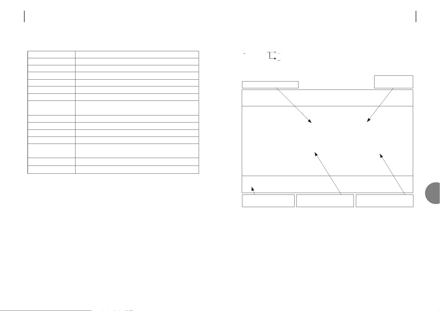
ATL USER GUIDE
OM100 Optical Multiplexer
71
7.5.2 User port performance
This screen provides alarm and performance information about the user port.
F9 Reset Trips
This will reset the trip counters for this port.
F10 Reset System Counters
This will reset performance counters for all optical and user ports. Pressing F10 on a master
unit will also reset all counters on the remotely connected slave unit.
Alarms marked [X] are active
The alarm flags are
shown in real time
Use the resettable counters
whilst diagnosing a problem
Use F5 and F6 to cycle
between ports
Counters remain at 0 until a
signal is first detected
OM100 Mon 01 Nov 2002 00:54:49
Performance > User Port
Urgent Alarm:Off Non-Urgent Alarm:On
Subsystem: LT
Port: 1
LOS Detected [x] BER > 1E-3 [ ]
AIS Detected [ ] BER > 1E-6 [ ]
Line Code Violations 0 Trip Counter 0
Available Seconds 100 Trip Counter 100
Unavailable Seconds 0 Trip Counter 0
Severely Errored Seconds 0 Trip Counter 0
Errored Seconds 0 Trip Counter 0
Error Free Seconds 100 Trip Counter 100
Press Escape to Exit
F1 Help F3 Previous Menu F4 Main Menu F5 Previous Channel
F6 Next Channel F7 Previous Subsystem F8 Next Subsystem F9 Reset Trips
F10 Reset System Counters
Performance Optical Transmission Line Performance counters for the optical line.
User Port AIS, LOS, BER, performance counters.
70 ATL USER GUIDE
OM100 Optical Multiplexer
Field Description
LOS detected Incoming optical signal failed, or been disconnected
Available seconds Total time the optical link has been in service
Unavailable seconds Total time this optical link has been out of service
Severely errored seconds Total time this optical link has suffered heavy errors
Errored seconds Total time this optical link has suffered light errors
Error free seconds Total time this optical link has been error free
Trip counters These are resetable counters useful whilst fixing, or testing the link
Press F9 to reset the counters
BER > 10E-3 Optical data contains a large number of bit errors
BER > 10E-6 Optical data contains a low number of bit errors
Laser fault Indicates the laser transmitter has failed, or is about ot fail
Line Code Violations This counter records the total violations detected
Backup Link Active Indicates if the backup optical link is active
(OM100 1+1 SF SM option only)
Link Optical link the data is refering to.
Line Physical connection to the unit.
7
Page 38

ATL USER GUIDE
OM100 Optical Multiplexer
73
7.6 SECURITY (CHANGE PASSWORDS)
This section deals with the security of the system. Access to the OM100 is password
protected. All password characters are displayed as asterisks (*), with <RETURN> as the default
password.
LOST PASSWORD
Fax Atl Telecom technical support on: ++44 2920 500 850
or send an e-mail to: [email protected]
Function
This field accepts the password currently attributed to the system. When
the password is recognised (on entry of the final password character) the
password field is enabled.
This field always displays its contents as asterisks, and has a maximum
length of 10 characters.
This field defaults to null after initial power on
This field is enabled when the operator enters text into the password field
Field
Old Password
New Password
Confirm Password
OM100 Mon 01 Nov 2002 00:57:40
Security > System
Urgent Alarm:Off Non-Urgent Alarm:On Test Active
Old Password [ ]
New Password [ ]
Confirm Password [ ]
Press Return to Accept or Escape to Cancel
F1 Help F3 Previous Menu F4 Main Menu
Security Change passwords.
72 ATL USER GUIDE
OM100 Optical Multiplexer
Description
Equipment sends the Alarm Indication Signal when a serious fault occurs
preventing them transmitting real data. Detecting this signal means there
is serious fault with equipment upstream of this unit.
Incoming signal lost. Either the connection between this unit and the
upstream equipment has been broken, or the upstream equipment
has failed.
Incoming data contains a high number of bit errors. Active if more than
2048 line code violations are detected within one second.
Incoming data contains a low number of bit errors. Active if more than 2
line code violations are detected within one second.
This counter record the total number of line code violations detected.
Counter to record the total time this user port has been in service.
Counter to record the total time this user port has been out of service.
Counter to record the total time this user port has suffered heavy errors.
Counter to record the total time this user port has suffered light errors.
Counter to record the total time this user port has been error free.
These are restable counters useful whilst fixing, or testing the link.
Press F9 to reset the counters.
Field
AIS Detected
LOS Detected
BER > 10E-3
BER > 10E-6
Line Code violations
Available seconds
Unavailable seconds
Severely errored
seconds
Errored seconds
Error free seconds
Trip counters
7
Page 39
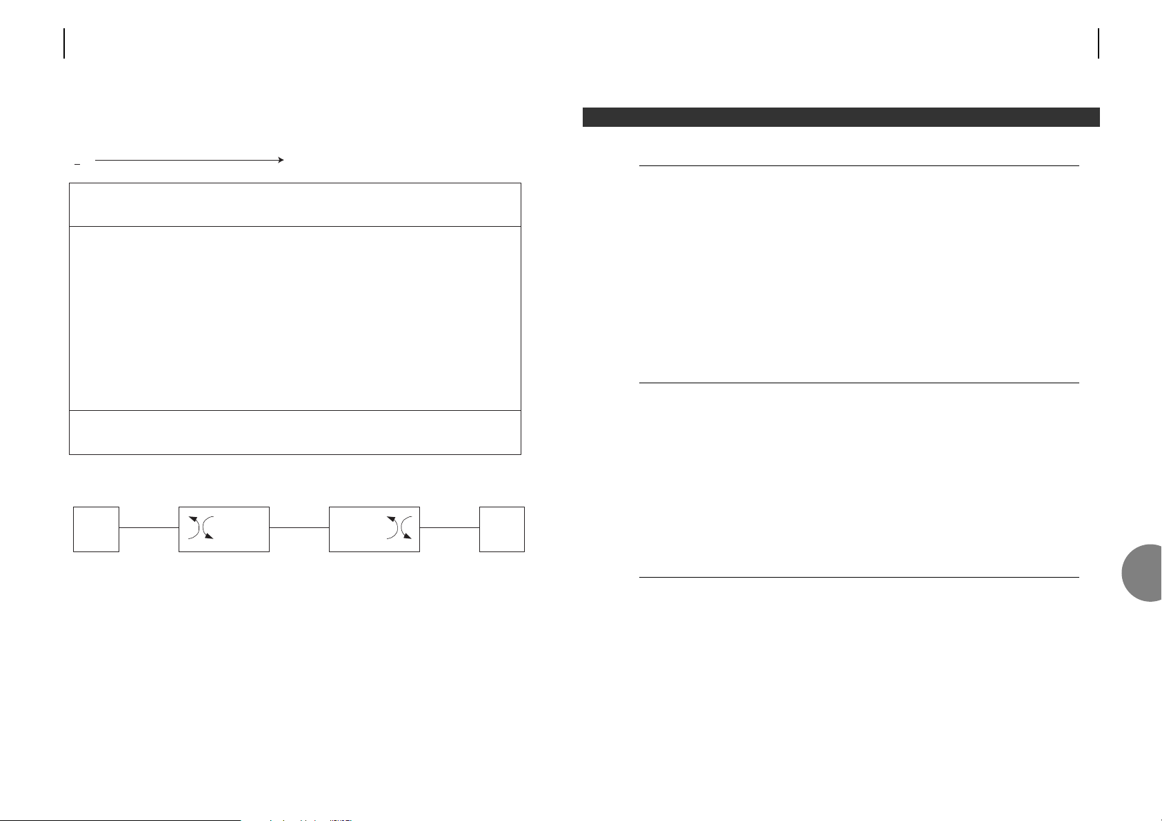
ATL USER GUIDE
OM100 Optical Multiplexer
75
Indicators
Desktop unit Status (global)
Optical 1 (status)
Optical 2 (status)
Ch1 (status)
Ch2 (status)
Ch3 (status)
Ch4 (status)
Master (configuration)
Test (mode)
Local loop
Loop back
Remote loop
Interfaces available
Desktop unit Port 1 G.703 120Ω
Port 2 G.703 120Ω
Port 3 G.703 120Ω
Port 4 G.703 120Ω
Optical Port Choices Dual fibre multimode
Single fibre single mode
Single fibre (1+1) single mode
Hand held terminal port
Local terminal port specification
Connector Standard, 9-way D-Type
Electrical Protocol EIA232 (RS232/V.28)
Default Settings 19200 bps, 8 bit, 1 stop, no parity
Maximum Baud rate 19200 bps.
Suitable equipment VT100 terminal, palm top PC or dial up modem
8 SPECIFICATIONS
8
74 ATL USER GUIDE
OM100 Optical Multiplexer
7.7 TEST
7.7.1 Setting data loopbacks
Note: All loopbacks are controllable from either the master, or slave. Loopbacks 1, 2, C1 & D1
are controllable by all OM100 management systems (i.e., local terminal, front panel buttons)
C
2
1
D
TE
ET
NT1 LT
Slave
OM100
Master
OM100
Exchange
Customer
OM100 Mon 01 Nov 2002 00:58:38
Test > Loopbacks
Urgent Alarm:Off Non-Urgent Alarm:On
Subsystem: LT
Port: 1
Loopback to Exchange Loopback To Customer
Towards Master Towards Slave
LL (Loopback 1) [ ] LL (Loopback C) [ ]
RL (Loopback 2) [ ] RL (Loopback D) [ ]
Press Return to Accept or Escape to Cancel
F1 Help F3 Previous Menu F4 Main Menu F5 Previous Channel
F6 Next Channel Use TAB to select fields
Test Enables various loopbacks.
Page 40
ATL USER GUIDE
OM100 Optical Multiplexer
77
Optical alarms
Traffic in fail (LOS)
Laser fault
BER>1x10
-3
BER>1x10
-6
Protection Switching Interface
Integrated in unit (optional)
Management
Local terminal port, remote modem connection,
limited push button configuration
Loopbacks
User port local & remote
Loopback control
Via Management stations
Push button configuration
Size
Customer unit – 169 x 49 x 206mm (W x H x D)
Power Supply Input Voltage Current Power Consumption
Customer unit -48V dc 100mA 4.8W nominal
Operating temperature
-10° ~ 50° C
Operating humidity
Maximum 95% non condensing
76 ATL USER GUIDE
OM100 Optical Multiplexer
User port specifications
Data rate 2.048Mbps
Use G.703, E1, primary rate ISDN
Connections RJ-45
Termination impedance 120Ω
Intrinsic jitter 0.09 UI peak to peak (20Hz – 100KHz)
Jitter transfer 30dB at 100Hz (1.5 UI in)
40dB at 1KHz (1.5 UI in)
< 60dB at 10KHz (0.2 UI in)
Maximum tolerable input Jitter >20 UI in at 100Hz
12 UI at 1KHz
2.5 UI at 10KHz
Additional delay > 50 µS
Maximum traffic clock offset > ±150ppm
Traffic Alarms
Traffic in fail (LOS)
AIS detected
BER>1x10
-3
BER>1x10
-6
Optical port specifications
Optical system
type
Atten. max
Atten. min
P
TX
P
RX
Wavelength
Con. No.
Con. type
Fibre type
Class
Multi-mode
dual fibre
18dB
0dB
-9dBm
-27dBm
850nm
2
ST
G.651
1
Single-mode
single fibre
25dB
0dB
-7dBm
-32dBm
1310/1550nm
1
FC-PC, ST or SC
G.652
1
1+1 single-mode
(single fibres)
25dB
0dB
-7dBm
-32dBm
1310/1550nm
2
FC-PC, ST or SC
G.652
1
8
Page 41

ATL USER GUIDE
OM100 Optical Multiplexer
79
9.1 LVD SAFETY STATEMENTS
1. This apparatus must be installed and maintained by SERVICE PERSONNEL.
2. Power Rating Information
DC Input
Voltage Range -36V to -60V.
Current 100mA.
110V AC adaptor (atl part number 5500000038)
Input: 110Vac, 150mA, 50/60Hz
Output: -48VDC 170mA
240V AC adaptor (atl part number 5500000041)
Input: 230Vac, 90mA, 50/60Hz
Output: -48VDC 170mA
The mains plug on the PSU input serves as the disconnect device, therefore a socket outlet
shall be installed near the equipment and shall be made accessible.
3. A protective earth connection must be made to the rear panel earthing stud using a
suitable bonding conductor if any G.703 cable is routed through an external environment,
or reliable earth connection is not provided to the DC input connector.
9.2 SAFETY STATEMENTS
The optical interface is classified as a CLASS 1 LASER PRODUCT.
The mains input connection has a HAZARDOUS VOLTAGE safety status.
The G.703 120Ω Digital Network Interface Port has a safety status of EARTHED SELV.
The TERM Port has a safety status of UNEARTHED SELV.
The –48Vdc input to the unit is classified as TNV2.
9.3 TELECOMMUNICATION SPECIFICATIONS
The equipment is in conformity with the following Common Technical Regulations and
National Standards:
Common Technical Regulations
CTR12 G.703 2Mbps, 120Ω, unstructured
CTR13 G.703 2Mbps, 120Ω, structured
9 SAFETY STATEMENTS AND COMPLIANCE NOTES
78 ATL USER GUIDE
OM100 Optical Multiplexer
Standards
G.651 Characteristics of multi-mode optical fibre cable
G.652 Characteristics of single-mode optical fibre cable
G.703 2.048Mbps electrical parameters
G.704 Frame structure
G.706 Framing algorithms
G.823 Jitter and wander limits
G.826 Error performance
I.431 Primary rate ISDN layer 1
M.3604 Maintenance principals
ETS 300 011 PRI user-network interface
ETS 300 233 Primary rate ISDN access
EN 60825 Optical safety
EN 60950 Safety
ETS 300 019-1-3 Environmental
EN55022 RF emissions limits
EN300386 V1.2.1 EMC requirements for network equipment
EN61000-4-2 ESD protection
EN61000-4-3 Electromagnetic field immunity
EN61000-4-4 Fast burst transients
EN61000-4-5 Surge Immunity
EN61000-4-6 Conducted disturbance immunity
EN61000-4-11 Voltage dips and short interrupts
9
Page 42

ATL USER GUIDE
OM100 Optical Multiplexer
81
AIS Alarm Indication Signal
BERT Bit Error Rate Test/Tester
CCITT International Telegraph and Telephone Consultative Committee
DCE Data Circuit-terminating Equipment
DTE Data Terminating Equipment
E1 The European standard 2.048Mbps digital carrier system
EBER Effective Bit Error Ratio
ETSI European Telecommunications Standards Institute
HDSL High bit rate Digital Subscriber Line
HHT Hand Held Terminal
ISDN Integrated Services Digital Network
ITU International Telecommunications Union
LED Light Emitting Diode
LOS Loss Of Signal
LT Line Terminator
LTU Line Terminating Unit
NT1 Network Terminator for PRI/BRI
PPP Point to Point Protocol
PRA Primary Rate Access
PRBS Pseudo Random Bit Sequence
PRI Primary Rate ISDN
Sa6 bits Message passing system used in Primary Rate Access
UI Unit Interval
UPS Uninterruptible Power Supply
V28 CCITT specification. Electrical characteristics for unbalanced double-current
interchange circuits
10 GLOSSARY OF TERMS
80 ATL USER GUIDE
OM100 Optical Multiplexer
10
Page 43
ATL USER GUIDE
OM100 Optical Multiplexer
83
Additional units may be ordered with the following part numbers.
Replacing 'x' with the following code
0 OM100 -48V DC powered only, no mains adaptor supplied
1
OM100 with PSU inline 110V input, -48V output
2
OM100 with PSU inline 230V input, -48V output
Short Code
Part
Number
Product Description
OM100 DF MM ST 1/352/12x
Dual fibre multimode with ST connector
(850nm)
OM100 SF SM FC/PC
Slave
1/352/31x
Single fibre single-mode with FC/PC connector
Slave (1310nm Tx / 1550nm Rx)
OM100 SF SM ST
Slave
1/352/32x
Single fibre single-mode with ST connector Slave
(1310nm Tx / 1550nm Rx)
OM100 SF SM SC
Slave
1/352/33x
Single fibre single-mode with SC connector Slave
(1310nm Tx / 1550nm Rx)
OM100 SF SM FC/PC
Master
1/352/41x
Single fibre single-mode with FC/PC connectors
Master (1310nm Rx / 1550nm Tx)
OM100 SF SM ST
Master
1/352/42x
Single fibre single-mode with ST connectors
Master (1310nm Rx / 1550nm Tx)
OM100 SF SM SC
Master
1/352/43x
Single fibre single-mode with SC connectors
Master (1310nm Rx / 1550nm Tx)
OM100 1+1 SF SM FC/PC 1/352/51x
1+1 Single fibre single-mode with FC/PC
connectors (1310nm & 1550nm)
OM100 1+1 SF SM ST 1/352/52x
1+1 Single fibre single-mode with ST connectors
(1310nm & 1550nm)
OM100 1+1 SF SM SC 1/352/53x
1+1 Single fibre single-mode with SC connectors
(1310nm & 1550nm)
APPENDIX A - ORDERING INFORMATION
82 ATL USER GUIDE
OM100 Optical Multiplexer
Page 44
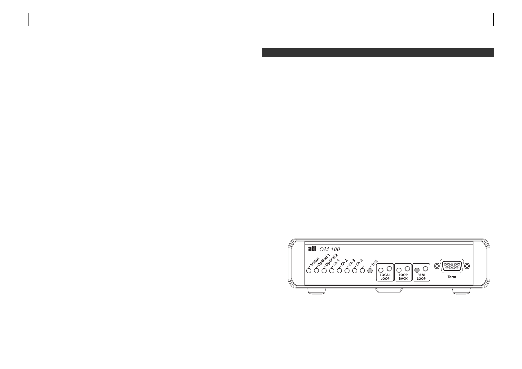
ATL USER GUIDE
OM100 Optical Multiplexer
85
INTRODUCTION
For users that don't have access to a PC, or prefer to configure the OM100 without the need
of a PC, the operating parameters can be configured using the front panel controls.
Front panel programming is carried out by placing the unit into Programming Mode by
pressing the "Local Loop" and Loop Back" buttons simultaneously and then releasing them.
Programming mode will be indicated by the Status LED flashing Green. The remaining LED
indicators will display the first parameter number and it's on/off state.
Note: If the front panel controls have been previously set to "Loops only" or "Input disabled"
from the VT100 Front Panel configuration screen, it will not be possible to enter Programming
Mode.
OPERATION
The "Local Loop" and "Loop Back" buttons are used to programme the parameters. Once
programming is complete, the "Remote Loop" button is pressed to store the new parameter
value (this must be done within 30 second of the last programming action or the modem will
automatically leave programming mode and discard the new values). When "Remote Loop" is
pressed, the modem reboots into its new configuration.
All of the configurable parameters have a "Parameter Number" displayed as a 3-bit binary
number on the loop active indicators (Local Loop = MSB), and On/Off indication displayed on
the Test indicator
.
In the above example, parameter 1 is displayed, with the test LED On. It can be seen from the
following table, that parameter 1 is the master / slave setting, and that with Test LED On
indicates the unit is in Master Mode.
Master
APPENDIX B - FRONT PANEL PROGRAMMING
84 ATL USER GUIDE
OM100 Optical Multiplexer
Note: OM100's must be configured for Master and Slave operation. Which is user
configurable in the software for 1xx and 5xx units. However, is fixed for the 3xx (slave) and
4xx (master) units. Please ensure you order and operate the 3xx and 4xx units in pairs.
DC Power Supply Cable
Section 3.3.1 gives details of items required to make a DC power cable. This complete cable
assembly may also be purchased from ATL using part number 6910000423 (short code OM100 DC CABLE)
AC Power Supply Adaptor
Use the following approved ATL part number and short codes to select.
OM100 PSU 110V 5500000038 Inline PSU, 110V input, -48V output
OM100 PSU 240V 5500000041 Inline PSU, 230V input, -48V output
Page 45

ATL USER GUIDE
OM100 Optical Multiplexer
8786 ATL USER GUIDE
OM100 Optical Multiplexer
Press "Loop Back" to turn option on or off.
Press "Local Loop" to step to the next parameter.
Remember to press "Remote Loop" to store the parameter values and reboot the modem,
once all parameters have been set to their desired on/off states.
The following table provides a full list of the parameters, and their values, available for
programming, using the front panel controls.
Note: Not all parameters that can be set via the VT100 screens, can be set via the front panel
controls (e.g. the User Port Lock Clock To Reference option).
Anything previously set by the VT100 screens that cannot be accesed from the front panel
controls will remain unchanged. Values that are set via the front panel will override screen
settings.
Note: On the OM100 SF SM Master and OM100 SF SM Slave units, the Master/Slave option is
locked, and any changes to the Master/slave option will not be stored.
Parameter
Number
Local
Loop
Loop
Back
Rem
Loop
Test
LED
Description
Off Slave
1 0 0 1
On Master
Off Port 1 Disabled
2 0 1 0
On Port 1 Enabled
Off Port 2 Disabled
3 0 1 1
On Port 2 Enabled
Off Port 3 Disabled
4 1 0 0
On
Port 3 Enabled
Off Port 4 Disabled
5 1 0 1
On Port 4 Enabled
Off APS Disabled
6 1 1 0
On APS Enabled
Page 46

88 ATL USER GUIDE
OM100 Optical Multiplexer
 Loading...