

Page 1

Ultrasound System
Getting Started
4708- 0027-03 Rev A April 2000
ATL Ultrasound
P.O. Box 3003
Bothell, WA 98041-3003
USA
Copyright E 2000 by ATLUltrasound All rights reserved Printed in USA
Page 2
Manufactured by ATL Ultrasound
22100 Bothell-Everett Highway
Bothell, WA 98021-8431
USA
Telephone (425) 487-7000 or (800) 426-2670
Fax (425) 485-6080
ITT International 4740016 SMS UI
Internet www.atl.com
CAUTION
UnitedStates federallawrestrictsthis device tosaleby
or on the order of a physician.
“Advanced 3DI”, “Advanced Technology Laboratories”, “ATL”, “CHROMA”, “Cineloop”, “Color Power Angio”, “ENTOS”, “HDI”,
“High Q”, and “Power Harmonic” are registered trademarks of ATL Ultrasound.
“DVS”, “Flash Contrast”, “High Definition”, “Power Motion”, “SonoCT”, “Tissue Specific”, and “WebLink” are trademarks of ATL
Ultrasound.
Non-ATL Ultrasound product names may be trademarks or registered trademarks of their respective owners.
ATL Ultrasound products may be manufactured under or operate in accordance with one or more of the following United States
patents and corresponding patents in other countries: U.S. Patent Numbers 4,581,636; 4,607,642; 4,543,960; 4,644,795;
4,887,306; 5,016,641; 5,123,415; 5,197,477; 5,255,682; 5,050,610; 5,226,422; 5,275,167; 5,207,225; 5,287,753; 5,215,094;
5,381,795; 5,386,830; 5,402,793; 5,390,674; 5,438,994; 5,471,989; 5,482,045; 5,476,097; 5,471,990; 5,456,257; 5,485,842;
5,482,047; 5,479,930; Re 35,148; 5,555,887; 5,617,863; 5,669,385; 5,645,066; D369,307; 5,634,465; 5,603,323; 5,706,819;
5,715,823; 5,718,229; 5,720,291; 5,879,303, 5,951,478; Re 36,564; 5,980,457; 5,961,462; 5,940,123; 5,908,389; 5,891,035;
5,860,924; 5,795,297; 5,846,200; 5,833,613. Other patent applications are pending in various countries.
Page 3

Read This First
About Your Manual Set
This manual is part of a manual set. The manual set addresses the reader who is familiar
with ultrasound techniques. Sonography training and clinical procedures are not included
in the manual set. The manual set includes the following:
· Getting Started: Introduces you to basic system features and concepts. When you
complete the procedures in this manual, you will know how to use these features and
understand the concepts of system operation.
· S can h ead s an d S af et y: Cont ains inf or m at ion about s af et y, s c anheads , biops y
guides, transesophageal and laparoscopic scanheads, and acoustic output.
· Reference Manual: Cont ains inf or m at ion t hat s uppor t s and am plif ies t he pr oc edur es
in Getting Started. It includes image management, maintenance, troubleshooting,
specifications, references, and a glossary.
· Usi n g Di si n f ect an t s an d G el s: Cont ains inf or m at ion about c om pat ible gels and dis -
infectants and disinfecting ATL products.
· Acoustic Output Tables: Cont ains inf or m at ion about m ec hanic al and t her m al index
precision and accuracy , the acoustic output default tables, and the acoustic output
tables.
· Medical Ultrasound Safety: Cont ains inf or m at ion about bioeff ec t s and biophy s ic s ,
prudent use, and implementing ALARA (as low as reasonably achievable).
· Operating Notes: Contains information that clarifies certain system responses that
might be misunderstood or cause user difficulty.
About Your Manual Set on Compact Disc (CD)
A CD is included in a pocket on the inside back cover of theGetting Started manual. The
CDcontainsthecompletemanualset,except fortheOperatingNotes. Theinstructionsfor
using the CD are on the last page of the Getting Started manual.
Please take the time to use the CD, complete the brief survey card included with the
manual set, and mail the survey card to us.
HDI 5000 Getting Started 4708-0027-03
1--1
Page 4

Read This First
Conventions Used in This Manual
These conventions are used in this manual:
· Allprocedures are numbered. Youmust completesteps inthe sequencethey are presented to ensure a reliable result.
· Bulleted lists indicate general information about a particular function or procedure.
They do not imply a sequential procedure.
· Control names appear in this manual like they appear on the system.
· Menuitemsortitlesappearingonthe display areshown inthe manuallike they appear
on the display.
· Theleft sideof the systemis to yourleft asyoustandin frontof thesystem, facing the
system.
· Scanheads and pencil probes both are referred to as scanheads, unless the distinction is important to the meaning of the text.
· “Select” means to place the cursor over an item and press SELECT once.
· “Double-select” means to place the cursor over an item, and quickly press SELECT
two times, like double-clicking with a computer mouse. Pressing SELECT too slowly
on double select will only highlight an item. Pressing it rapidly will initiate an action.
System Conventions
These conventions are used in the system:
· Thesoftwarethat runs thesystemusesgraphicdisplayelementssimilartothoseused
in many personal computers. References to these elements in the software or in the
m anual ar e def ined in t he glos s ar y in t he Ref er enc e M anual .
· On a menu, protocol, or other display, a highlight bar indicates that the item or name
contained within theboundariesof thehighlight bar is inthe processof beingselected.
Pressing the SELECT control or other related control actually selects the item,
assigns a value to a system parameter, or initiates the action related to theselected
item.
· On a menu, an underlined letter indicates that pressing the underlined letter on the
system keyboard will have the same effect as choosing the menu item with the trackball and the SELECT control.
· On the system keyboard, pressing the Superkey and another designated key, for
example 2D Maps, allows youto changea system parameter without using a menu.
Using the Superkey is a quick way to change a system parameter that normally
appears on a menu.
1--2
HDI 5000 Getting Started 4708-0027-03
Page 5

Read This First
· Pressing a key or control the first time initiates a mode change, function, oroperation,
or changes the value of a system parameter. Pressing the same key or control a secondtimeresumesapreviousmodeorsystemparameter,cyclestothenextsetting,or
endsthe function or operation. All MENUcontrols work this way,andit can be quicker
to press the MENU control than to select Close, especially to exit a submenu.
· On a menu, protocol, or other display, text that is lighter in color than the other text on
thedisplayindicates thattheitem or name containedwithintheboundariesisnotavailable for selection in that menu, protocol, or display.
· A
· A
· SelectingClose fromamenuordisplayremoves themenuor displayfrom thescreen.
· Selecting + or -- increases or decreases the value of the parameter.
· An ellipsis ... on a menu indicates that a submenu is available from the selection.
· To highlight a menu, protocol, or other display item, use the trackball to move thecur-
sor to the particular item.
· To enter text into a text field, use the keyboard.
· The softkeys, located on the lower right of the control panel, assume functions based
on your control selections. For example, pressing VCRCTRL results in the softkeys
assuming these VCR control functions: PLAY, PAUSE, STOP, FF (Fast Forward),
and REWIND.
or indicates an option or alternative for selection.
or indicates that an option or alternative has been selected.
System Upgrades and Manual Set Updates
ATLUltrasoundiscommittedtoinnovationandcontinued improvement.Upgrades maybe
announced that consist of hardware or software improvements. Updated manuals will
accompany those system upgrades.
Customer Comments
If you have questions about the manual set, or you discover an error in the manual set,
pleasecalltheATLCustomerService at (800) 433-3246;orifyou are outsidetheUSA, call
thenearest ATLoffice,listedlater in thissection. Youcanalsosendelectronic mail(e-mail)
to ATL Technical Publications at the following address:
HDI 5000 Getting Started 4708-0027-03
1--3
Page 6
Starting an Exam
"""" T o prepare the system for operation:
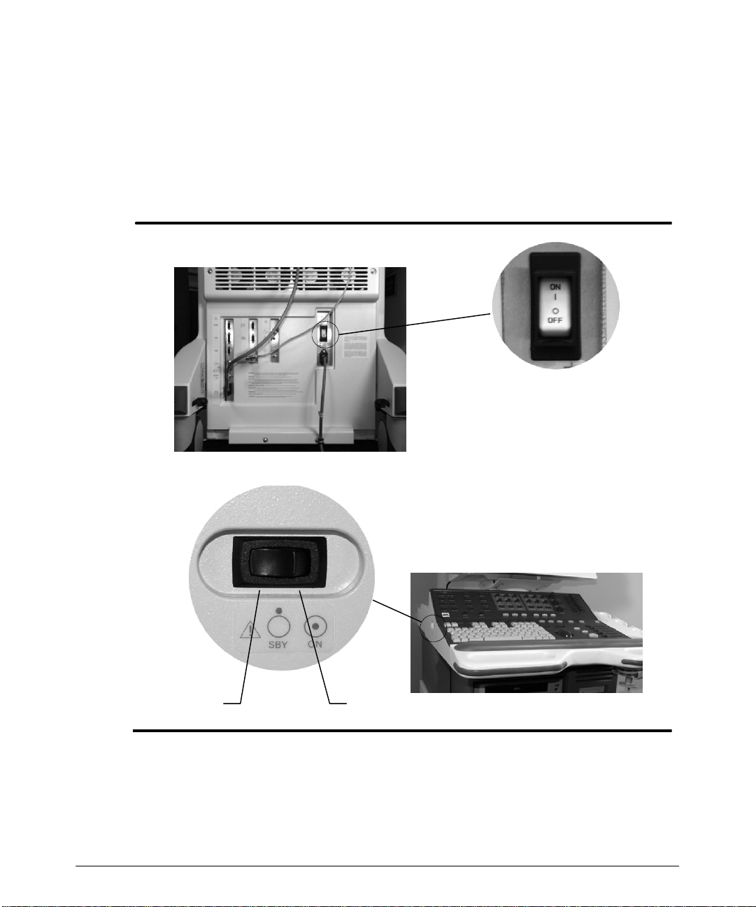
1. Ensure that the circuit breaker on the rear of the system (Figure 2--1) is set to OFF.
2. Ensure that the ON/STANDBY switch is set to STANDBY (Figure 2--1).
Circuit breaker
Figure 2--1. System Circuit Breaker and ON/STANDBY Switch Locations
HDI 5000 Getting Started 4708-0027-03
ON/STANDBY switch
ONSTANDBY
2--1
Page 7

Starting an Exam
3. Plugthesystem power cordintoagrounded outlet,ratedfor at least15 amperes. Systems used in North America should only be connected to hospital-grade outlets.
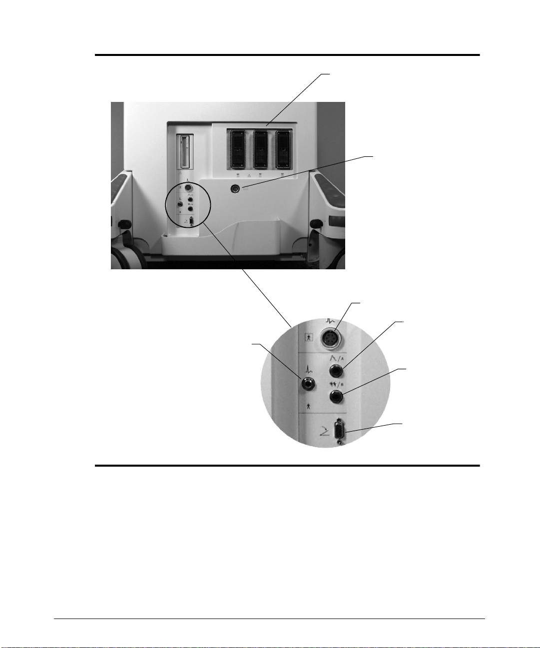
4. Connec t a s c anhead t o one of t he s c anhead r ec ept ac les ( F igur e 2 -- 2) .
a. Position the scanhead connector against the scanhead receptacle.
b. Turn the locking lever clockwise.
"""" T o connect the footswitch assembly:
1. Locat e t he f oot swit ch connect or on t he f r ont of t he syst em (F igure 2 -- 2).
2. Connect the footswitch assembly to the footswitch connector.
"""" T o connect physio transducers:
1. Prepare the ECG leads, phono, pulse, and auxiliary transducers, as necessary.
2. Connect the ECG, physio, and auxiliary connectors, as necessary, to the system
r ec ept ac les ( F igur e 2 -- 2) .
2--2
HDI 5000 Getting Started 4708-0027-03
Page 8
Starting an Exam
HighLevel
ECG
Scanhead receptacles
Pencil probe port
ECG
Pulse
(Auxiliary
Channel A)
HDI 5000 Getting Started 4708-0027-03
Phono
(Auxiliary
Channel B)
Footswitch
Figure 2--2. Connection Receptacles
2--3
Page 9
Starting an Exam
"""" T o turn on power to the system:
1. O n t he rear of t he syst em, swit ch t he circuit breaker swit ch t o ON ( F igur e 2 -- 1) .
2. O n t he lef t side of t he syst em, swit ch t he O N/ S TANDBY s wit c h ( F igur e 2 -- 1) t o ON.
3. Waitaboutoneminutewhile the system performsits initializationand self-testroutine.
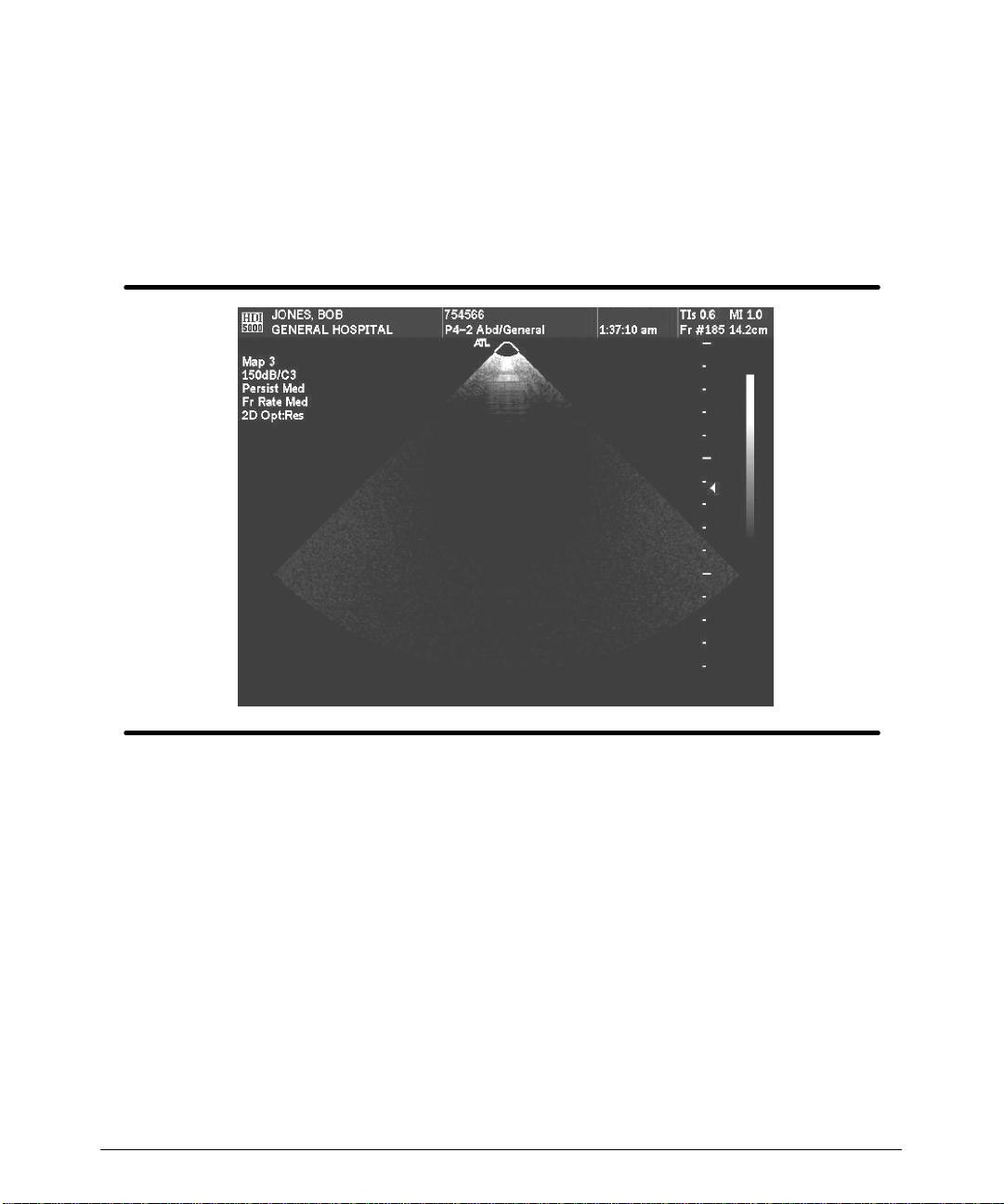
A 2D display appears on the video monitor (Figure 2--3). (If a pencil probe is the only
scanheadconnected to thesystem, a scrolling display appears on thevideo monitor.)
"""" T o turn off power to the system:
1. On the left side of the system, switch the ON/STANDBY switch to STANDBY
( F igur e 2 -- 1) .
2. The system displays amessage, “Initiating power-down...Will powerdownwhenfinished saving files.” and then the system shuts down.
3. O n t he rear of t he syst em, swit ch t he circuit breaker (F igure 2 -- 1) t o OFF.
2--4
Figure 2--3. 2D Display
HDI 5000 Getting Started 4708-0027-03
Page 10
Starting an Exam
CAUTIONS
S Standby does not result in an immediate cessation of system activity.A pow-
er-downsequence occurs, similar tothe initialization that occurs whenpower
is turned on. Do not inadvertently cycle power, when this power-down
sequence is occurring.
S To prevent electrical damage to the system or possible loss of patient data,
after turning the system off, always wait 5 to 10 seconds before turning the
power on again.
S Priorto disconnecting the power cord from the electrical outlet, switch the cir-
cuit breaker to the OFF position.
"""" T o enter new patient data:
If you havethe Worklist optionor the Digital Video Streaming (DVS)option, the procedure
for patient data entry differs from the following procedure. Refer to the “Image Manangem ent ” s ec t ion of t he Ref er enc e M anual , if your syst em has t he Worklist opt ion. Ref er t o the
“ Digit al Video S t r eam ing O pt ion” s ec t ion of t he Ref er enc e M anual, if your syst em has the
DVS option.
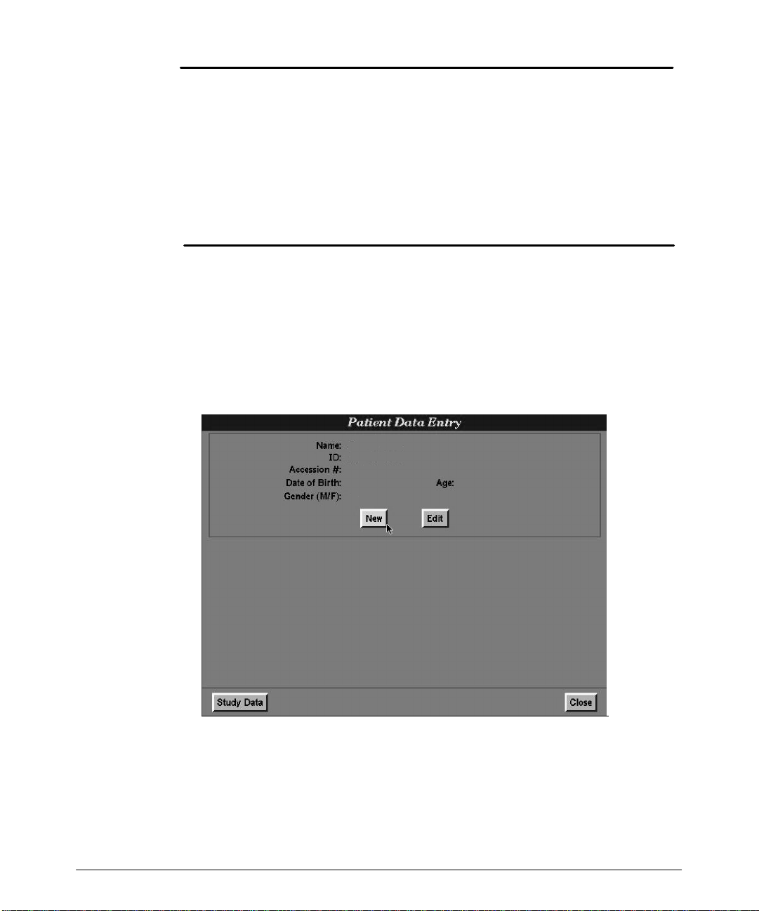
1. Press the Patient Data key to display the Patient Data Entry form (Figure 2--4).
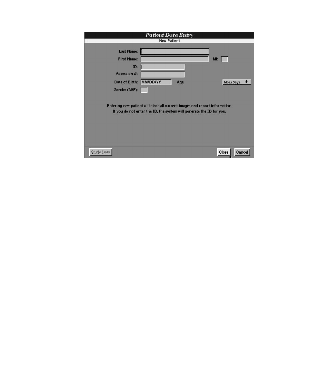
2. Select New t o dis play t he New P at i en t f orm (F igure 2-- 5).
HDI 5000 Getting Started 4708-0027-03
Figure 2--4. Patient Data Entry Form
2--5
Page 11
Starting an Exam
Figure 2--5. New Patient Form
3. Enter patient information: Last Name, FirstName,MI(middle initial), ID,
Accession
#, Date of Birth, and Gender,andpress the Return key after each entry.Age is cal-
culated from the date of birth you enter.
-- WiththeImage Management option,if youdonotenter anID, the systemwillgen-
erate an ID and assign it to the patient.
-- Anaccession number is an optionalentry assigned to eachpatient file by an insti-
tution for internal information management purposes.
4. Press the Patient Data key,orselectClose,tosave thepatient informationand toexit
the display.
"""" T o edit patient data:
1. P r es s t he P at i en t Dat a k ey t o dis play t he P at i en t Dat a E n t ry f orm (F igure 2-- 4).
2. Select Ed i t t o dis play t he Ed i t Pati en t f orm (F igure 2-- 6).
2--6
HDI 5000 Getting Started 4708-0027-03
Page 12

Starting an Exam
3. E dit pat ient inf or m at ion: L ast Name, First Name, MI ( m iddle init ial) , ID, Accessi o n #.
DateofBirth,andGender, andpresstheReturnkeyafter completingeachfield.
is calculated from the date of birth you enter.
-- WiththeImage Management option,if youdonotenter anID, the systemwillgen-
erate an ID and assign it to the patient.
-- Anaccession number is an optionalentry assigned to eachpatient file by an insti-
tution for internal information management purposes.
Figure 2--6. Patient Data Entry: Edit Patient Form
Age
4. Press the Patient Data key,orselectClose,tosave thepatient informationand toexit
the display.
HDI 5000 Getting Started 4708-0027-03
2--7
Page 13

Starting an Exam
"""" To enter study data:
1. Select Study Data on the Patient Data Entry form to display additional study data
fields (Figure 2--7).
Note
Figure 2--7. Study Data Form
Verify that the date and time are accurately displayed. You will need to press the
Patient Data key to display the time and again to return to Patient Data Entry
2. If necessary, change the units of measure on the Study Data
form:
.
a. Select the units of measure to display a drop-down list. Units of measure include
thefollowing:for height,cm(centimeters)andin(inches); forweight, lb
oz (ounces), kg (kilograms), and gms
(grams).
(pounds),
b. From the drop-down list, select the units of measure you want.
3. Enter the patient’s height and weight in the units of measure shown on the display .
Press the Return key after each entry. The patient’s body surface area will be calculated and displayed based on the height and weight you entered.
4. If appropriate, enter the LMP (last menstrual period) date. Press the Return key.The
systemautomaticallycalculates and displaysthe gestational age using theLMPdate,
GA(LMP).A calculationofthe estimated date of delivery by thelast menstrual period,
EDD (LMP), is also calculated and displayed.
-- If theLMP is unknown, youcan enter an Estab. (Established) Due Date and then
press Return. The system will calculatean LMP dateanddesignate it witha c, for
“calculated value.”
2--8
HDI 5000 Getting Started 4708-0027-03
Page 14
Starting an Exam
5. Enter the Estab. Due Date and press the Return key.
6. For Twins, enter Y or N (Yes or No) and press the Return key.
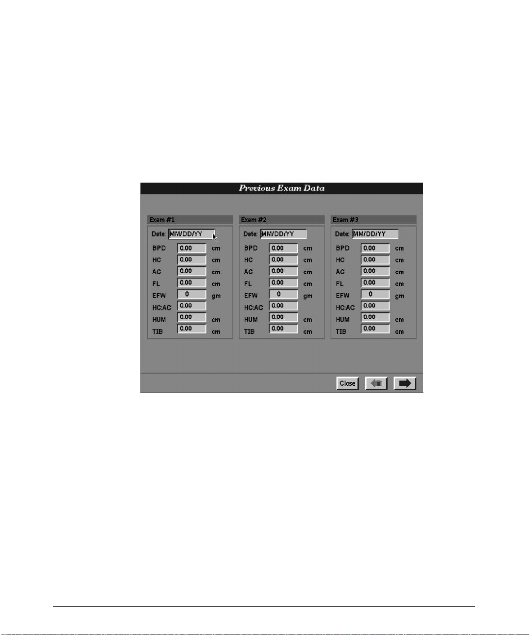
7. If previous ultrasoundexam data exists,select PrevExamData.ThePreviousExam
Data form is displayed (Figure 2--8).
a. Enter the information into the Previous Exam Data form. There are 10 exams
available, and you should enter the data in chronological order, beginning with
Exam #1
.
b. When finished, select Close to exit the Previous Exam Data
Figure 2--8. Previous Exam Data
form.
HDI 5000 Getting Started 4708-0027-03
2--9
Page 15
Starting an Exam
"""" T o select a scanhead for image optimization:
1. Ensure that the desired scanhead is securely connected to the scanhead receptacle.
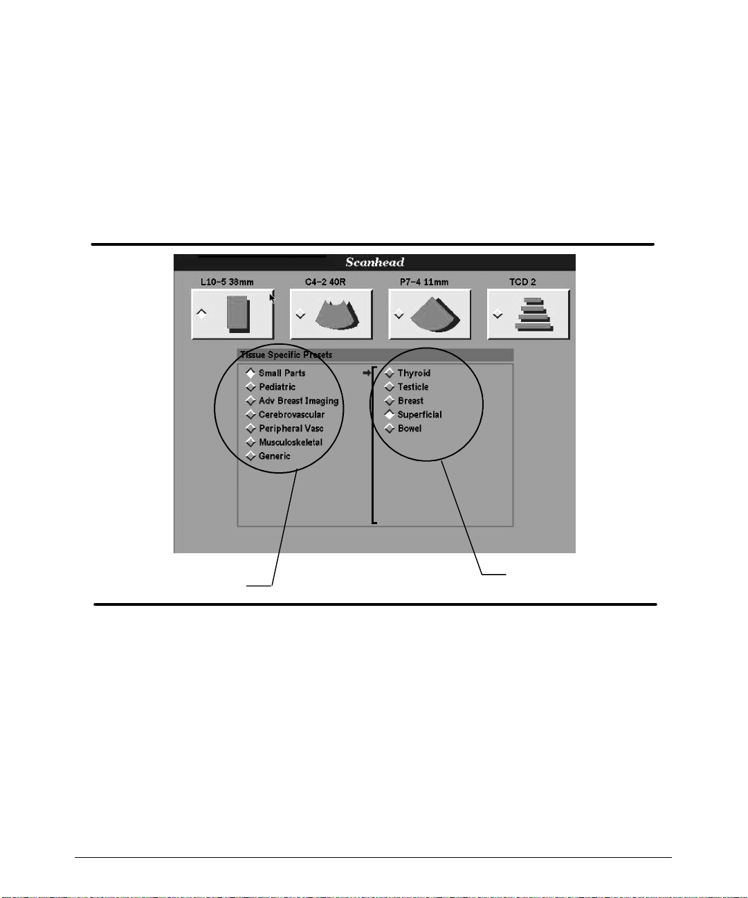
2. Press the Scanhead key to display the Scanhead display, which shows the scanheads that are currently connected to the system (Figure 2--9).
3. Select the scanhead that you want. Alist of clinical options is displayed based on the
scanhead that you select (Figure 2--9).
Note
2-- 10
Clinical options
Tissue Specific
presets
Figure 2--9. Scanhead Display
4. Select theclinical option that you want.A correspondinglist ofTissueSpecific presets
displays across from the list of clinical options (Figure 2--9).
5. Select a Tissue Specific preset. The system initializes with the scanhead, clinical
opt ion, and t he Tis s ue S pec if ic pr es et y ou hav e s elec t ed ( F igur e 2 -- 10) .
If scanhead initialization fails: check the scanhead connector, reselect the scanhead,
or select another scanhead.
HDI 5000 Getting Started 4708-0027-03
Page 16

Starting an Exam
C5--2 40R
Abdomen/General
Initializing...
Figure 2--10. Tissue Specific Scanhead Initialization
HDI 5000 Getting Started 4708-0027-03
2-- 11
Page 17

Using Setups
Setupsare system parameters. There are three typesof setups: system, Tissue Specific
preset, and software. Changing any setup takes effect immediately. System setups are
savedthrough a power cycle. Tissue Specific preset setups are only in effect until thecurrentTissueSpecific preset is changed ora power cycleoccurs.Softwaresetupsallowyou
or an ATL representative to install a temporary option on your system. You can use this
option for a specified period of time before it is automatically disabled.
TissueSpecific preset setups can be saved as part of a user-defined Tissue Specific preset using the Quick Save key.
Image Management and Acquisition Parameters setups are addressed in detail in the
“ I m age M anagem ent ” and “ Digit al Video S t r eam ing O pt ion” s ec t ions of t he Ref er enc e
M anual. A ll s et ups and s et t ings ar e ex plained in t he glos s ar y in t he Ref er enc e M anual.
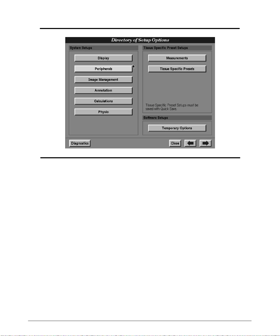
Directory of Setup Options
TheDirectoryof SetupOptionslistsgroupsofsystemandTissueSpecificpresetsetups
t hat are available in t he syst em (F igure 3 -- 1). Depending upon your syst em opt ions, t he
content of your Directory of Setup Options may vary.
HDI 5000 Getting Started 4708-0027-03
3-- 1
Page 18
Using Setups
Figure 3--1. Directory of Setup Options (Example)
3-- 2
HDI 5000 Getting Started 4708-0027-03
Page 19

Using Setups
"""" To use the Directory of Setup Options:
1. P r es s t he Setups key. T he Directory of Setup Options appear s ( F igur e 3 -- 1) .
2. Select one of the setup groups listed in the directory. The setups appear.
3. At the bottom of the setups displays, there are several control selections. Select the
following, as necessary:
-- System Defaults: Having changed setup values, you may want to revert to the
originalsetupvalueswithout individuallyresetting all of thesetups. Selecting Sys-
tem Defaults allows you to do that. System Defaults does not appear on the
Directory of Setup Options; it appears on the setups displays.
-- Close: Closes the display, exits Setups, and returns the system to the active
imaging mode.
-- Setups Directory: Displays the Directory of Setup Options.
-- Left arrow: Moves back through the displays of the different setup groups.
-- Right arrow: Moves forward through the displays of the different setup groups.
-- Diagnostics: Appears on the Directory of Setup Options only; it provides
access to the system diagnostics.
System Setups
"""" T o change setups:
1. Select a setup group from the Directory of Setup Options.
2. Select the setup values or enter text into a text field for a setup.
3. Select Close or press the Setups key.
Perform the examples that follow to become familiar with changing setups, and then use
these basic operations to change the range of setups as required for your uses.
HDI 5000 Getting Started 4708-0027-03
3-- 3
Page 20
Using Setups
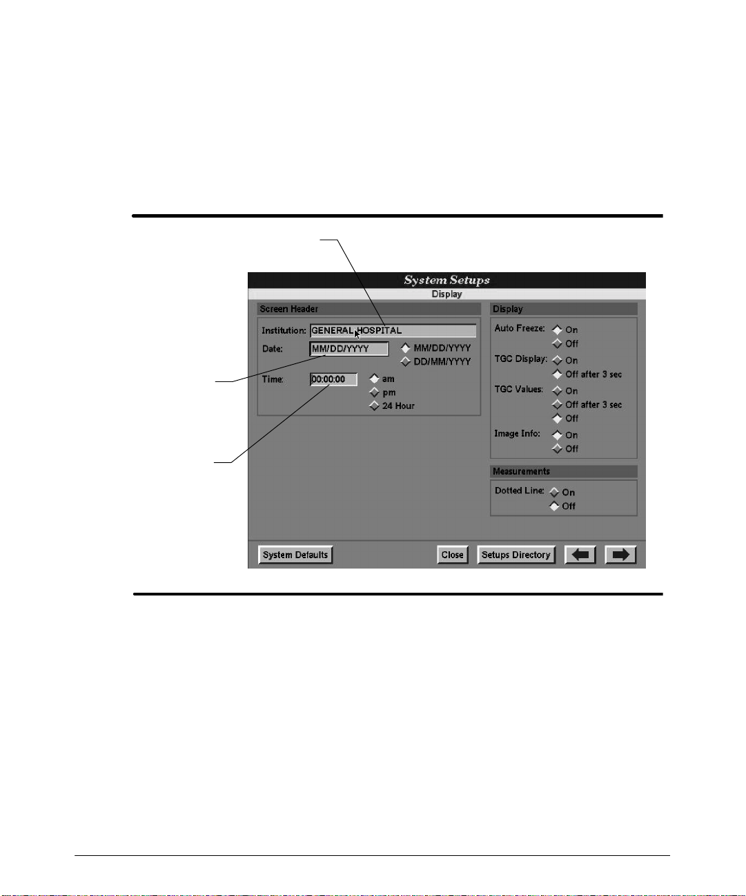
"""" To enter the name of the institution:
1. In Display setups, select the Institution field in the Screen Header area
(Figure 3--2). The text entry cursor appears in the Institution field.
2. Enter the name of the institution.
3. Select Close to exit the Display setups and return to the imaging mode. The institution name that you entered appears on the image display.
Institution field
Date field
Time field
Figure 3--2. Display Setups
3-- 4
HDI 5000 Getting Started 4708-0027-03
Page 21

Using Setups
"""" To enter the date:
1. In Display setups, select the desired date format (MM/DD/YY or DD/MM/YY)inthe
Screen Header area. The diamond changes shading to indicate selection of the date
f or m at ( F igur e 3 -- 2) . W hen y ou ent er t he dat e, it m us t c or r es pond in f or m at t o t his
selection.
2. Move the cursor to the left side of the date entry field.
3. Press the SELECT control to activate text entry.
4. Enter the date in the format selected.
5. Select Close to exittheDisplaysetups and returnto theimaging mode. Thedate that
you entered appears on the image display .
"""" To enter the time:
1. In Display setups, select the desired timeformat (am,pm,or24Hour)intheScreen
Header area. The diamond changes shading to indicate selection of the time format
( F igur e 3 -- 2) . W hen y ou ent er t he t im e, it m us t c or r es pond in f or m at t o t his s elec t ion.
2. Move the cursor to the time entry field.
3. Press the SELECT control to activate text entry.
4. Enter the time in the format selected.
5. Select Close to exittheDisplaysetups andreturn to the imagingmode.The timethat
you entered appears on the image display .
HDI 5000 Getting Started 4708-0027-03
3-- 5
Page 22

Using Setups
"""" To set the Doppler results display:
1. On the Directory of Setup Options, select Measurements.TheMeasurements
setups appear.
2. Select the Doppler result that you want displayed during High Q Doppler analysis
(Figure 3--3).
3. Repeatstep 2 untilyou have selectedupto sixDopplerresults for display (fivefor Cardiology clinical options).
4. Select Close to exit the Measurements setups.
5. DuringDopplerimaging, the Doppler resultsthat youselectfromthe DopplerResults
Display list will be invoked for the number of heart cycles selected in the next procedure.
3-- 6
Cardiology
Non-Cardiology
Figure 3--3. Measurements Setups: Doppler Results Displays
HDI 5000 Getting Started 4708-0027-03
Page 23
Using Setups
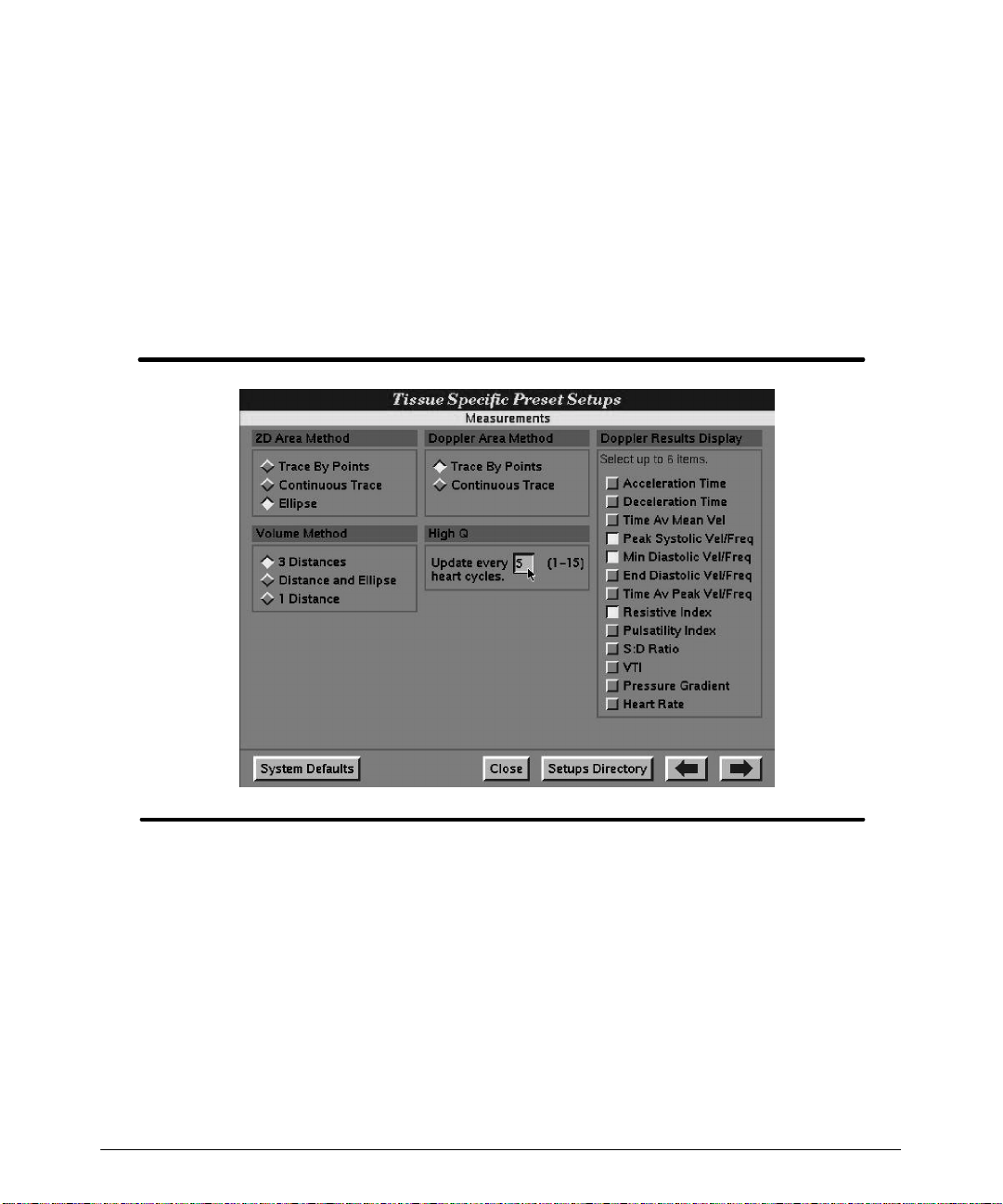
"""" T o set the number of heart cycles by which High Q Doppler analysis will update:
1. On the Directory of Setup Options, select Measurements.TheMeasurements
setups appear.
2. Select the High Q entry field to activate text entry (Figure 3--4).
3. Enter the number of heart cycles: the entry must be a number between 1 and 15.
4. Select Close to exit the Measurements setups.
5. The Doppler results will be updated every 1to 15 heart cycles,depending upon your
selection in the High Q Measurements setups.
Figure 3--4. Setting the High Q Update Interval
HDI 5000 Getting Started 4708-0027-03
3-- 7
Page 24
Using Setups
Tissue Specific Preset Setups
Under a preset name, you can save thecurrent setupsand system control settings. ATL
hasoptimized severalpresets andcalledthem TissueSpecific presets.These presetsare
related to aclinical option and to a scanhead. They set up the system for specific tissue
imaging and are intended to reduce the need for control adjustments.
Thefollowingprocedures deal withcreating your ownpresets, deletingpresets,andtransferring presets between systems.
"""" T o use the Quick Save key to save a preset:
1. Ensure that the controls and setups are set for your application and scanhead.
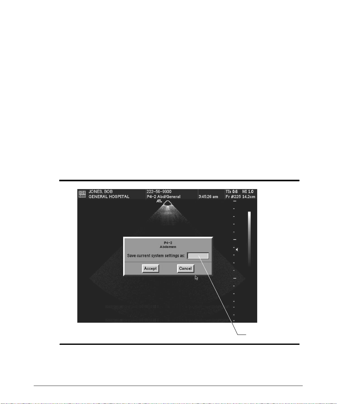
2. Press the Quick Save key to display the dialog box (Figure 3--5).
3. To clear the Save current system settings as field, press the Backspace key.
(Otherwise, the system default name will be used for your preset.)
4. Enter a name for your preset in the Save current system settings as field
(Figure 3--5). You can enter five characters.
3-- 8
Name field
Figure 3--5. Quick Save Dialog Box
HDI 5000 Getting Started 4708-0027-03
Page 25
Using Setups
5. Select Accept to save the preset.
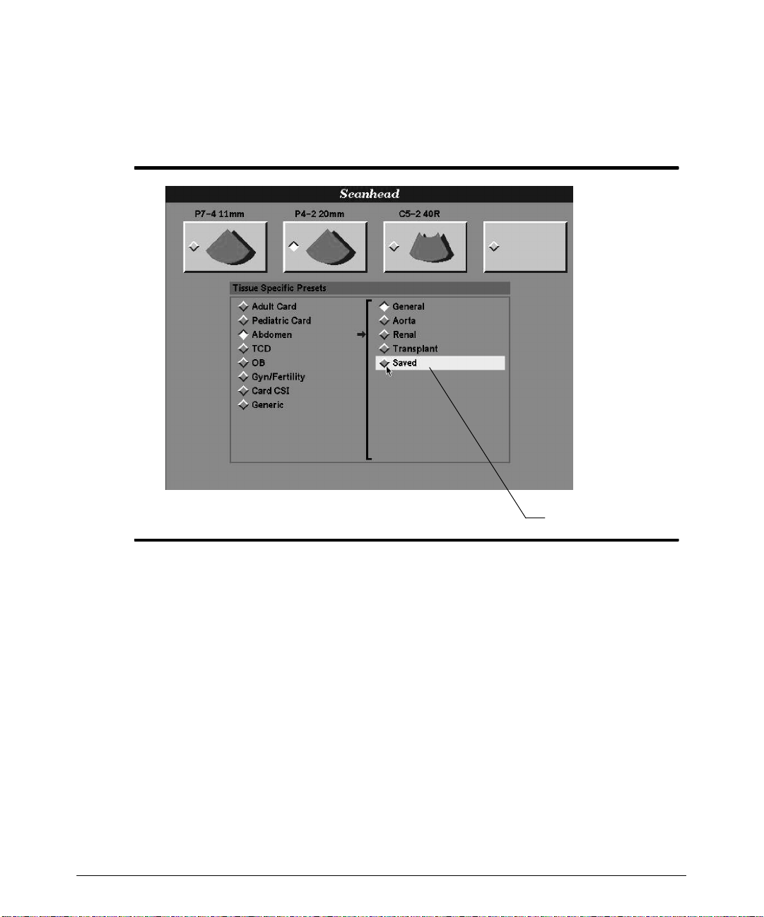
6. To verify that your preset has been saved, press the Scanhead key. Your preset
appears in the right column of the Scanhead display(Figure 3--6). You can nowuse
this preset with the specific scanhead and clinical option.
Figure 3--6. User-defined Optimized Preset
HDI 5000 Getting Started 4708-0027-03
Saved preset
3-- 9
Page 26
Using Setups
"""" T o delete a preset:
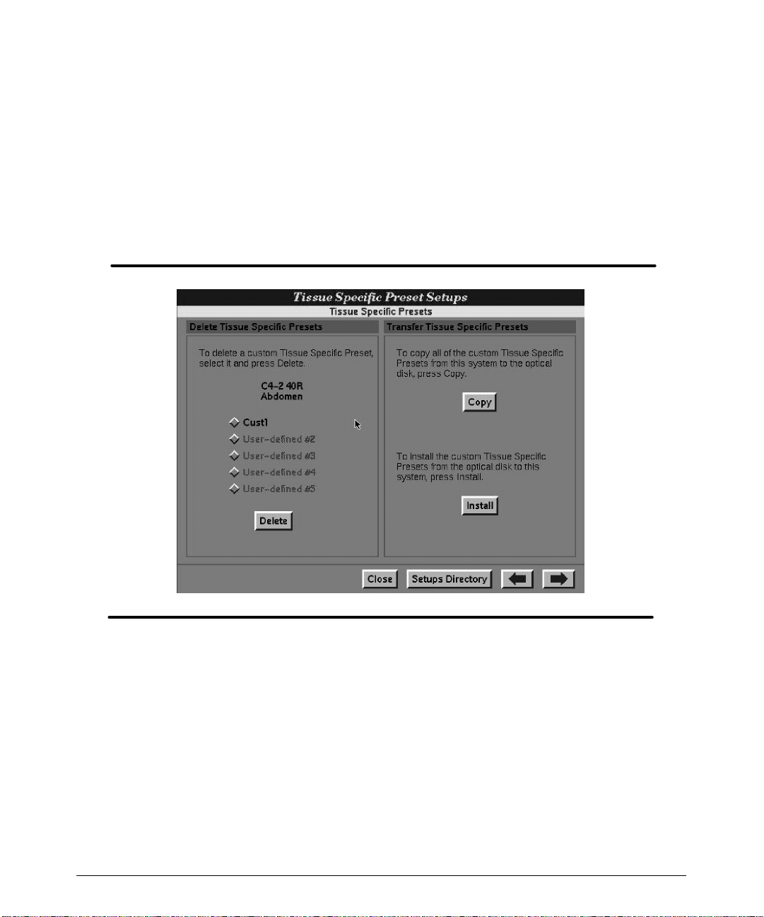
1. On the Directory of Setup Options, select Tissue Specific Presets.TheTissue
Specific Presets Setups appear . (Figure 3--7).
2. Select the preset that you want to delete. (ATL Tissue Specific presets cannot be
deleted.)
3. Select Delete to delete the selected presets. (Respond to the system dialog box as
appropriate.) The custom preset is deleted from the list.
4. Select Close to exit the Directory of Setup Options.
3-- 10
Figure 3--7. Tissue Specific Presets Setups
HDI 5000 Getting Started 4708-0027-03
Page 27
Using Setups
"""" T o copy presets from a system to an optical disk:
1. On the Directory of Setup Options, select Tissue Specific Presets.TheTissue
S p eci f i c P reset s S et u p s appear. ( F igur e 3 -- 7) .
2. Insert a formatted optical disk into the disk drive.
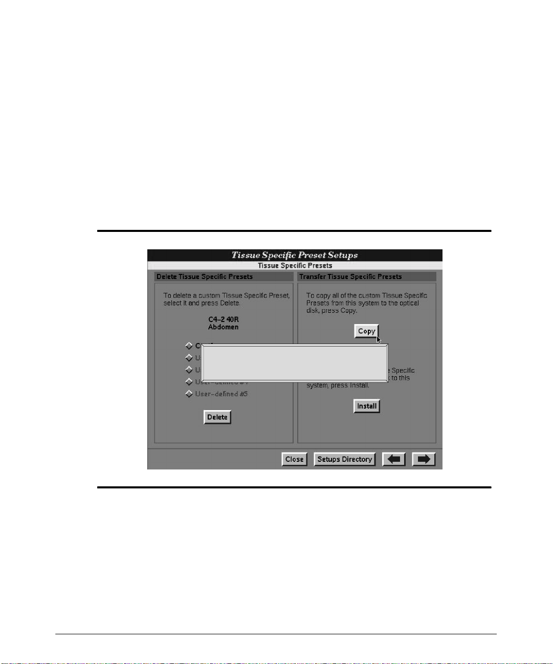
3. Select Copyto copy the presets to the optical disk. A status message appears, and
theindicator onthe disk drive lights toindicate that thepresets are copyingto the optical disk (Figure 3--8).
4. Remove the optical disk:
a.
Press NET/DISK.
b. Select Eject. The optical disk is ejected from the system optical disk drive.
Figure 3--8. Copying Presets Message
HDI 5000 Getting Started 4708-0027-03
Copying Tissue Specific Presets to the optical disk.
Pleasewait...
3-- 11
Page 28
Using Setups
"""" T o transfer presets from an optical disk to the system:
CAUTION
1. On the Directory of Setup Options, select Tissue Specific Presets.TheTissue
2. Insert the formatted optical disk with presets into the optical disk drive.
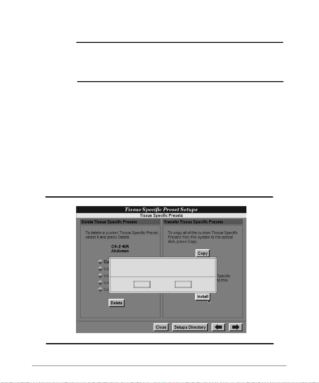
3. Select Install to transfer the presets from the optical disk to the system. The dialog
4.
5. After installing the presets, thelist of presets is not automatically updated. You must
Transferringpresetsfrom asystem withone version of systemsoftware to anothersystemwitha differentversionof systemsoftwarecancorruptthepresetsdatabase. This can result in poor system performance. Before transferring presets
betweensystems, ensurethatthesoftwareversionsarethesame.Yourcustomer
service representative can supply you with this information.
S p eci f i c P reset s S et u p s appear. ( F igur e 3 -- 7) .
box in Figure 3--9 appears. (Respond to the dialog box as appropriate.)
Remove the optical disk:
a. Press NET/DISK.
b. Select Eject. The optical disk is ejected from the system optical disk drive.
exit and re-enter theTissue Specific Presets Setups to see the new list ofpresets.
3-- 12
Installing files from optical disk.
Do you want to overwritethe existing custom presets?
Install Cancel
Figure 3--9. Transferring Presets Dialog Box
HDI 5000 Getting Started 4708-0027-03
Page 29
Using Setups
Software Setups
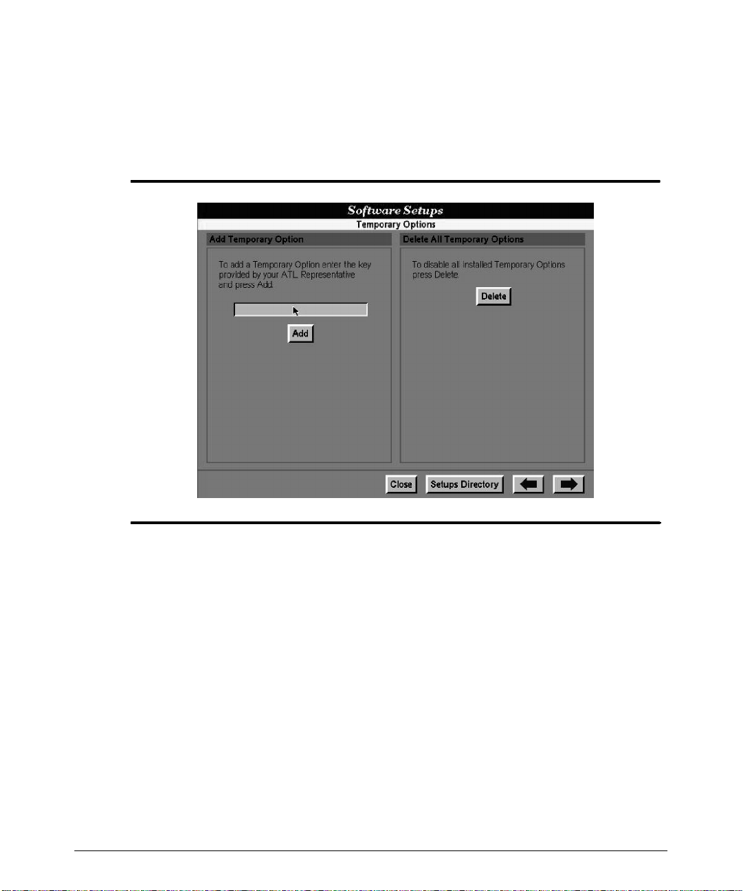
"""" T o add a temporary option:
1. On theDirectory of Setup Options, select Temporary Options.TheTemporary
Options setups appear (Figure 3--10).
Figure 3--10. Temporary Options Setups
2. Enterthe “key” into the textentry field. (Youcanobtain the key froman ATLrepresentative.)
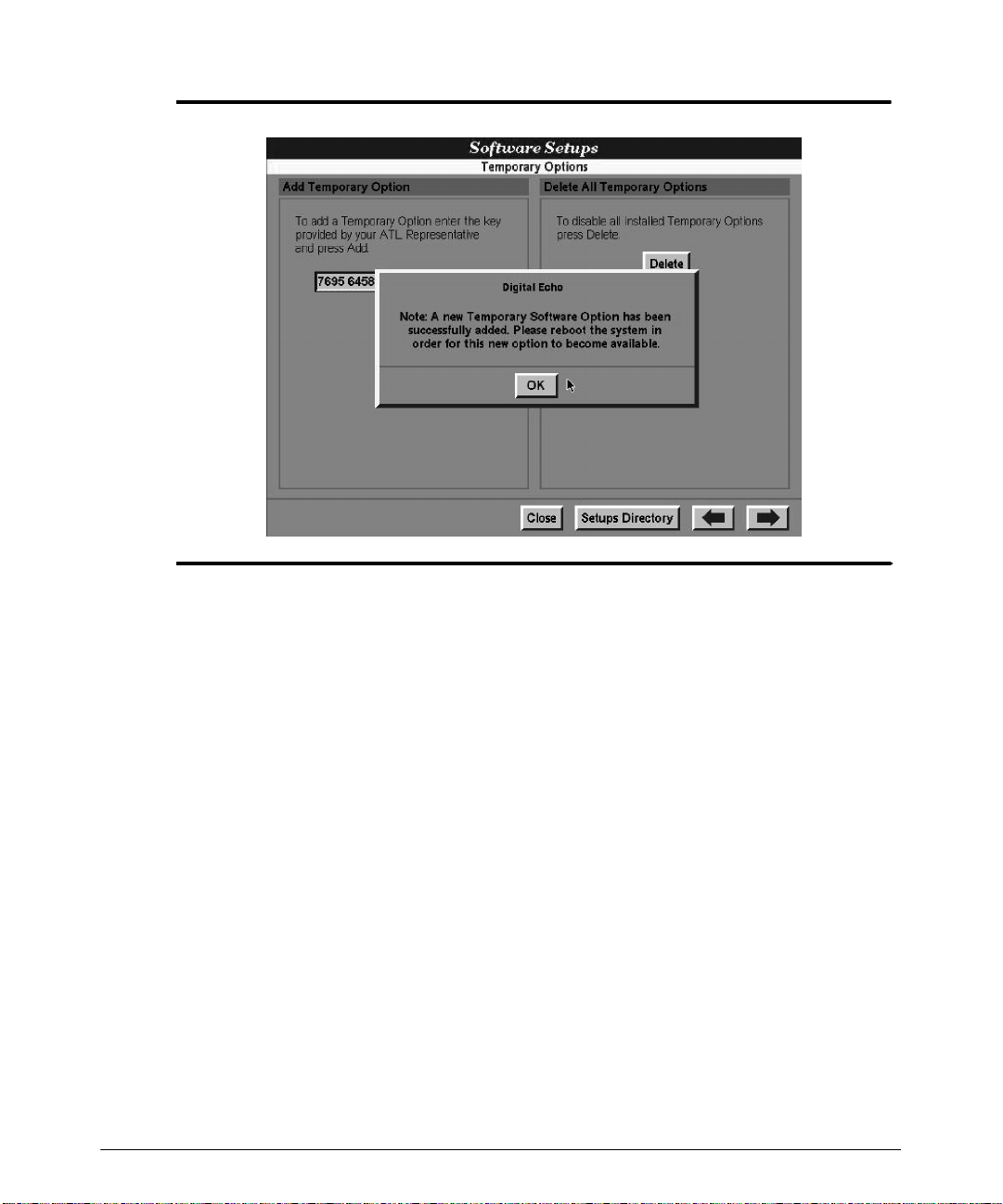
3. Select Add. A dialog box appears describing the temporary software option and how
t o enable it ( F igur e 3 -- 11) .
HDI 5000 Getting Started 4708-0027-03
3-- 13
Page 30
Using Setups
Figure 3--11. Adding a Temporary Software Option Dialog
4. To enable a temporary software option: turn off system power, wait severalseconds,
and then turn the system on.
5. When you turn the system on, adialog box appears, describing the temporary option
and the period of time it will remain enabled.
6. Select OK. The dialog is removed and imaging can begin. The temporary option is
available for the period of time indicated in the dialog. Each time power is turned on,
thedialogwillbeupdatedwiththetime remainingforanyadditionaltemporary options.
"""" T o delete all temporary options:
1. On theDirectory of Setup Options, select Temporary Options.TheTemporary
Options s et ups appear ( F igur e 3 -- 10) .
2. SelectDelete.Adialogboxappears, indicating that alltemporarysoftware optionswill
be deleted.
3. Select OK. The dialog box is removed.
4. To update the system software options: turn off system power,wait several seconds,
and then turn the system on.
3-- 14
HDI 5000 Getting Started 4708-0027-03
Page 31
Imaging
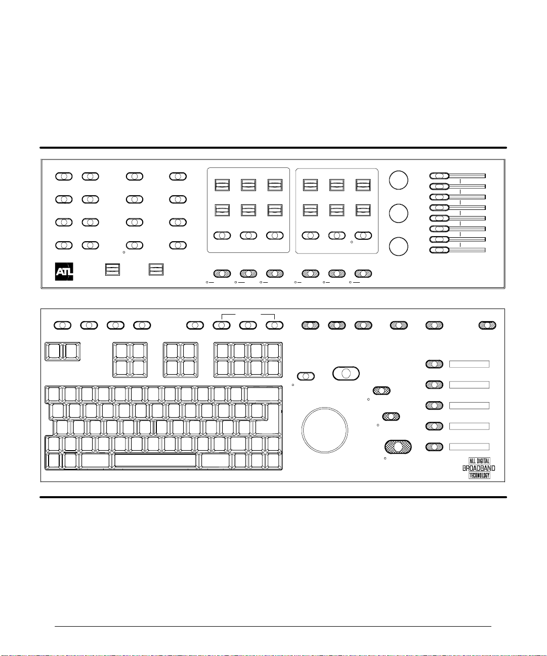
The primary imaging controls are on the control panel (Figure 4--1). There are also imaging c ont r ols on m enus ( F igur e 4 -- 2) . T he f ollowing pr oc edur es des c r ibe how t o adjus t t he
controls to affect the ultrasound image.
MENU
2D / MM
3D / CINE
PWR
PHYSIO
DOPPLER
TRIGGERS
COLOR
NET/DISK
VOLUME
PROTOCOL PARAMS TIMERS
3D OPT
L/R INVERT
TOP/BOT
TDI
TOOLBAR
OUTPUT
REVIEW
END EXAM
DEL IMG
VCR CTRL
COLOR/ DOPPLER
SCALE
BASELINE ANG COR
STEER
PULSED CW
OPTIMIZATION
FR RATE
FILTER ZONES
PRIORITY
SV SIZE COMPRESS
0/60°
INVERT
COLOR PWR IMG MMODE
HARMONICDUAL 2D/COLOR ADV MEASDEL MEASAREACALCS DISTANCE
COMP IMG
UPDATE
2D / M MODE
SEC WIDTH
CURSOR
SELECT
DEPTHFOCUS
ZOOM
HD ZOOM
2D
RECORD
PRINT
2D GAIN
DOP GAIN
COL GAIN
FREEZE
CAPTURE
3D UNCAL
HIGH Q
R
HDI 5000 Getting Started 4708-0027-03
Figure 4--1. Control Panel
4-- 1
Page 32
Imaging
"""" T o select an imaging mode:
After initialization, a 2D image appears on the screen. (If a pencil probe isthe onlyscanhead connected, then a scrolling display appears.)
1. To start a different imaging mode, press the PULSED, CW, COLOR, PWR IMG, M
MODE,or2D control.
-- In pulsed Doppler, 2D Color, or Color M-mode imaging, you can press the TDI
control to start Tissue Doppler Imaging.
-- Enable Harmonics or Contrast Specific Imaging by selecting the appropriate Tis-
sue Specific preset.
-- During 2D imaging, press COMP IMG to start SonoCT Real-time Compound
Imaging (an L12-5 38 mm or 50 mm scanhead must be selected).
2. Press an imaging control a second time to turn off that imagingmode, or press 2D to
return to 2D imaging.
"""" To use the MENU controls:
1. Press the MENU control that is appropriate for your imaging mode.
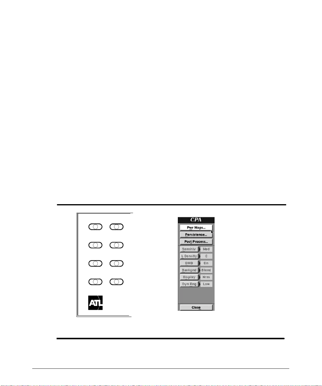
2. On the menu, select the setting (Figure 4--2). The selection turns on oroff, orcycles
through the available settings, and the display changes accordingly. If thereis a submenu associated with the selection (indicated by an ellipsis, ...) then it is displayed.
4-- 2
MENU
2D / MM
PWR
DOPPLER
COLOR
3D / CINE
PHYSIO
TRIGGERS
NET/DISK
MENU controls
Sample menu
Figure 4--2. Menu Controls
HDI 5000 Getting Started 4708-0027-03
Page 33
Imaging
"""" To adjust GAIN and TGC:
1. Rotatethe 2DGAIN,COL GAIN,orDOP GAIN control to change the amount ofgain
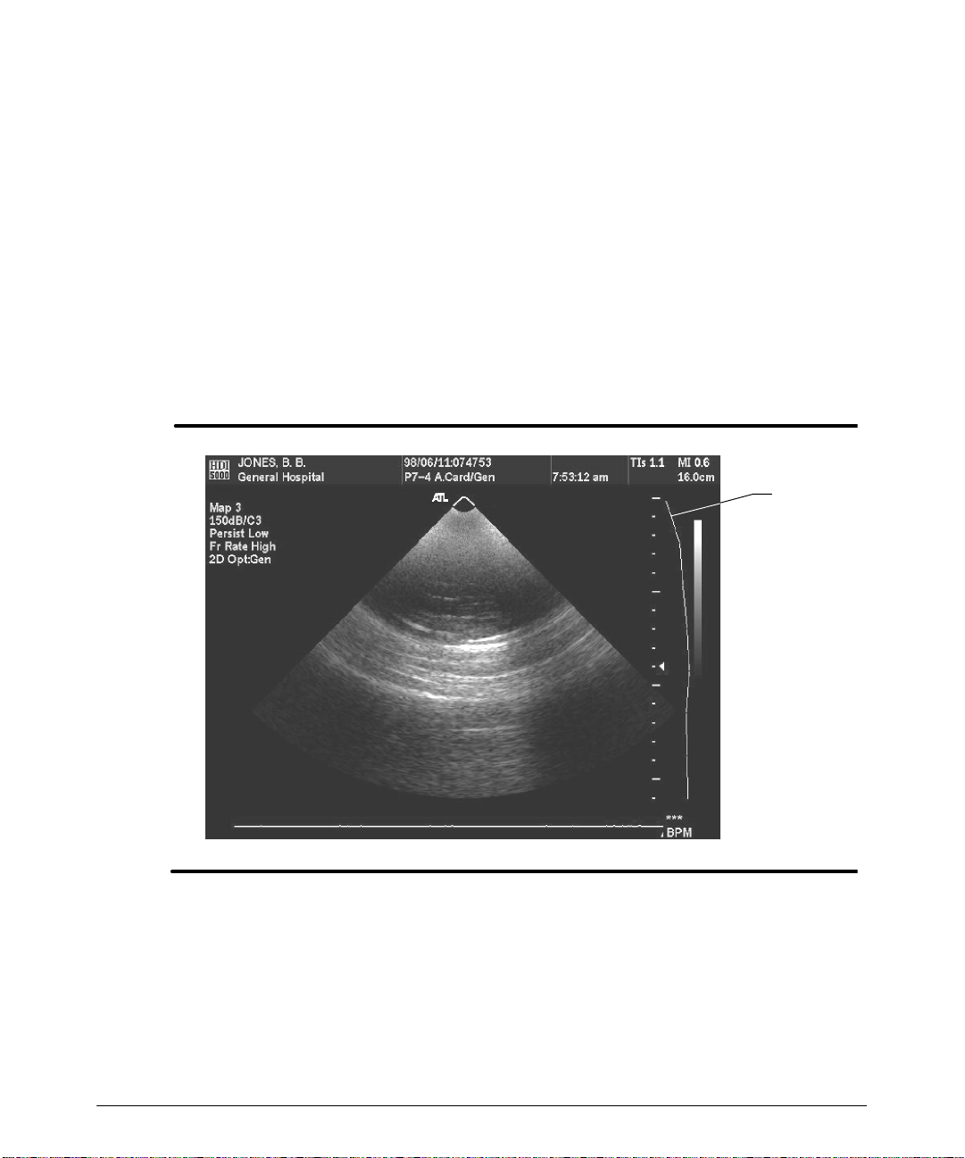
that is applied to the overall 2D, Color, or Doppler image. The TGC (time gain compensation) curve will move to reflect the change in 2D gain (Figure 4--3).
Notes
S Display of the TGC curve depends upon the TGC Display setting in Display set-
ups.
· The COL GAIN control changes gain for the Color image and Power image.
2. Slide a TGC slide control tothe left to decrease theamount ofTGC applied tothespecific area in the 2D image that corresponds to that TGC slide control.
3. Slide a TGC slide control to the right to increase the amount of TGC applied to the
specific area in the 2D image that corresponds to that TGC slide control.
TGC
curve
Figure 4--3. TGC Curve
"""" To optimize the image for patient specific imaging:
Press the specific OPTIMIZATION control (3D OPT, FR RATE, HARMONIC,or
2D/COLOR)until you have optimizedtheimagefor thepatientand the imagingmode.The
settings availabledependuponthe clinicaloptionselected.(The ImageInfodisplaysetup
turns on or off display of the optimization setting.)
HDI 5000 Getting Started 4708-0027-03
4-- 3
Page 34
Imaging
"""" To use SonoCT Real-time Compound Imaging:
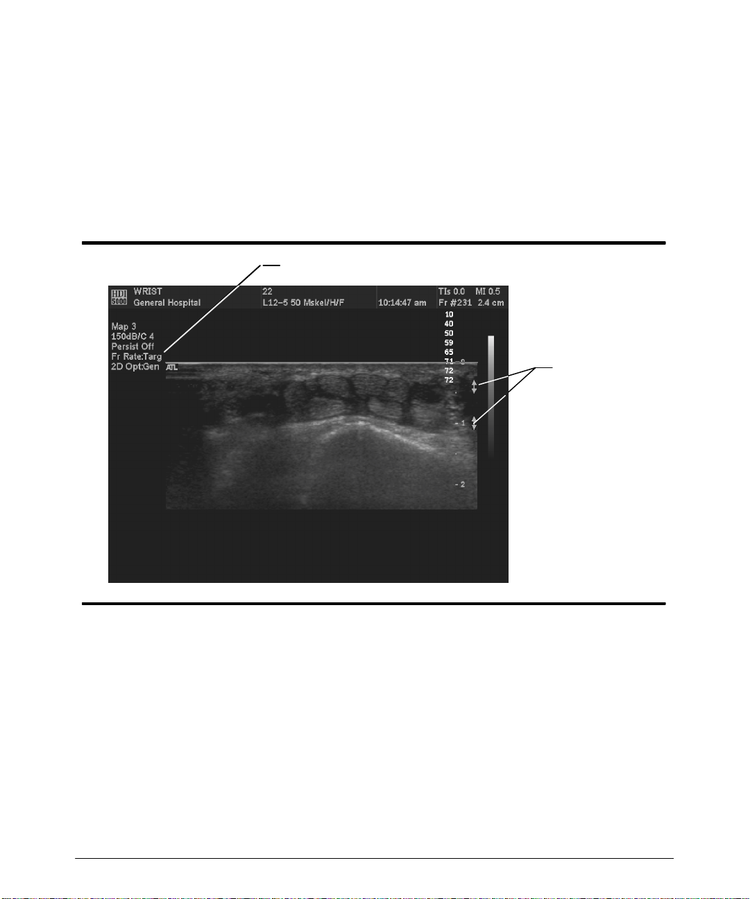
1. During 2D imaging, press COMP IMG. Compound imaging begins.
2. Press FRRATE toselect the scanning geometry that provides thebest image quality.
Fr Rate:Surv and FrRate:Targ are the two alternatives (Figure 4--4).
3.
Use the ZONES and FOCUS controls to adjust the number and location of the focal
zones.
4. Press COMP IMG a second time to return to 2D imaging.
Frame Rate setting: Survey or Target
Compound
imaging focal
zones
4-- 4
Figure 4--4. Compound Imaging
HDI 5000 Getting Started 4708-0027-03
Page 35
Imaging
"""" T o adjust OUTPUT :
· Press up on the OUTPUT control to increase the acoustic output ofthe system. The
image display and the TI and MI values change to reflect a change in output.
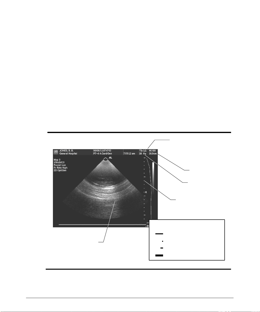
(Figure 4--5).
· Press down on the OUTPUT control to decrease the acoustic output of thesystem.
· To change thethermalindexdisplay: presstheSuperkeyand TI key,orselectTIs/TIb
on the 2D/MMode menu.
· To get more information about the thermal index, press the TI Help key.
"""" T o adjust DEPTH:
· PressupontheDEPTH control to decrease the display depth of the image. The
image, the depth scale, the depth annotation, and the frame rate changeto reflect a
change in depth (Figure 4--5).
· Press down on the DEPTH control to increase the display depth of the image.
TI and MI values
(TI options include
TIs, TIb; TIc is avail-
able for transcranial.)
2D image
Figure 4--5. Output and Depth Display
HDI 5000 Getting Started 4708-0027-03
Depth
annotation
Frame rate
Depth scale
Depth scale marker values
Skin line marker at 0 cm
Small marker every 0.5 cm
Medium marker every 1 cm
Large marker every 5 cm
4-- 5
Page 36

Imaging
"""" T o change the compression curve:
· PressupontheCOMPRESS control to selecta differentcompression curve, increas-
ingthe dynamic range. The total systemdynamic range availableis150dB. The compression curve number (Cn) changes to reflect the compression curve selection.
· Press down on the COMPRESS control to select a different compression curve,
decreasing the dynamic range.
"""" To adjust the focal zone depth and number of focal zones:
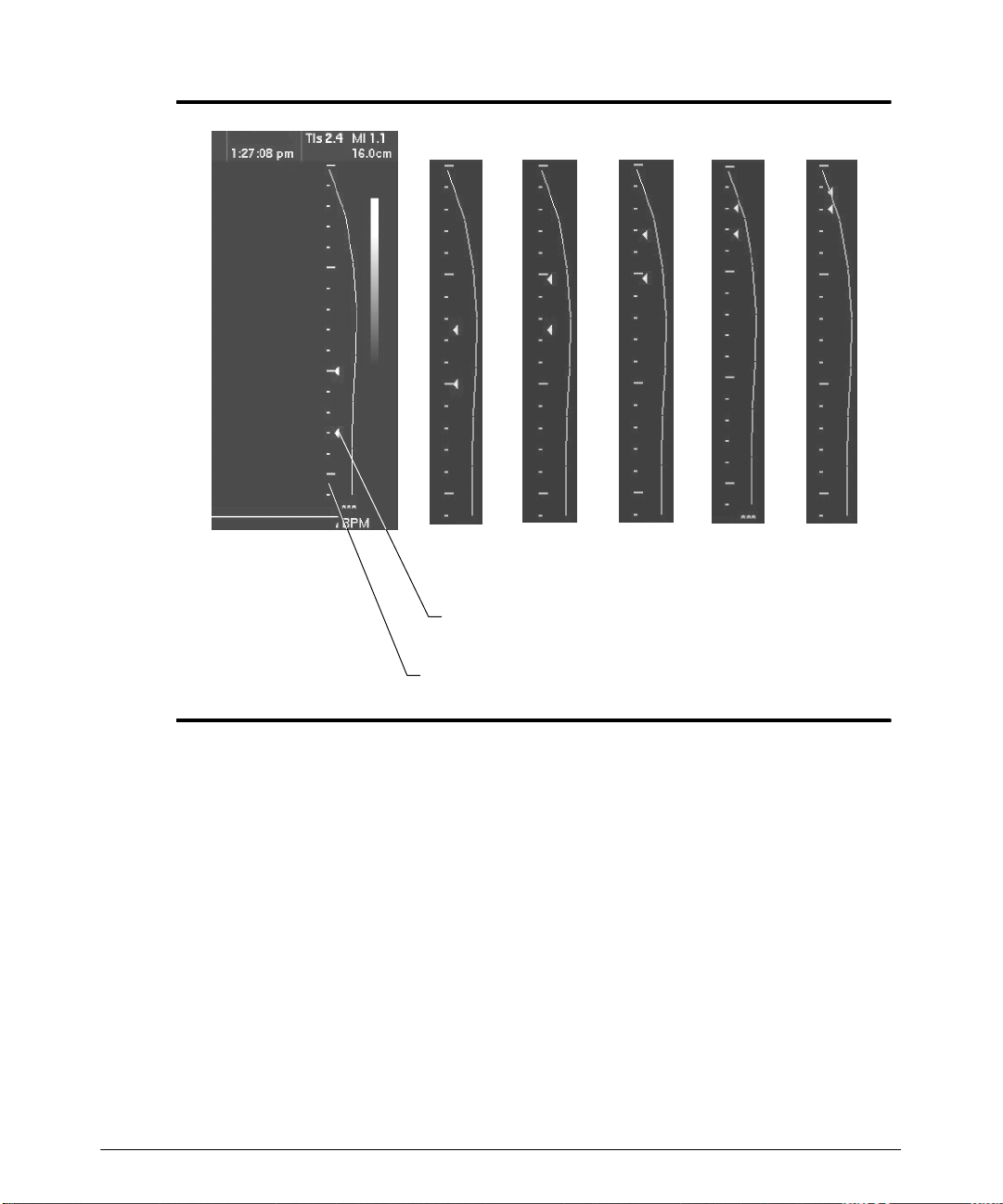
· Press upontheF O CUS c ont r ol t o m ov e t he f oc al z one ( F igur e 4 -- 6) t owar d t he t op of
the display, along the depth scale, to the depth of interest.
· Press down on the FOCUS control to move the focal zone toward the bottom of the
display.
· PressupontheZONES controltoincreasethenumber of focal zones andchangethe
distance between focal zones.
· Press down ontheZONEScontrol todecrease the numberof focalzones and change
the distance between focal zones.
4-- 6
HDI 5000 Getting Started 4708-0027-03
Page 37
Imaging
Progression of focal zone markers as FOCUS
is pressed up.
Focal zone marker (Up to five
markers can be displayed.)
Depth scale
Figure 4--6. Focal Zones
HDI 5000 Getting Started 4708-0027-03
4-- 7
Page 38
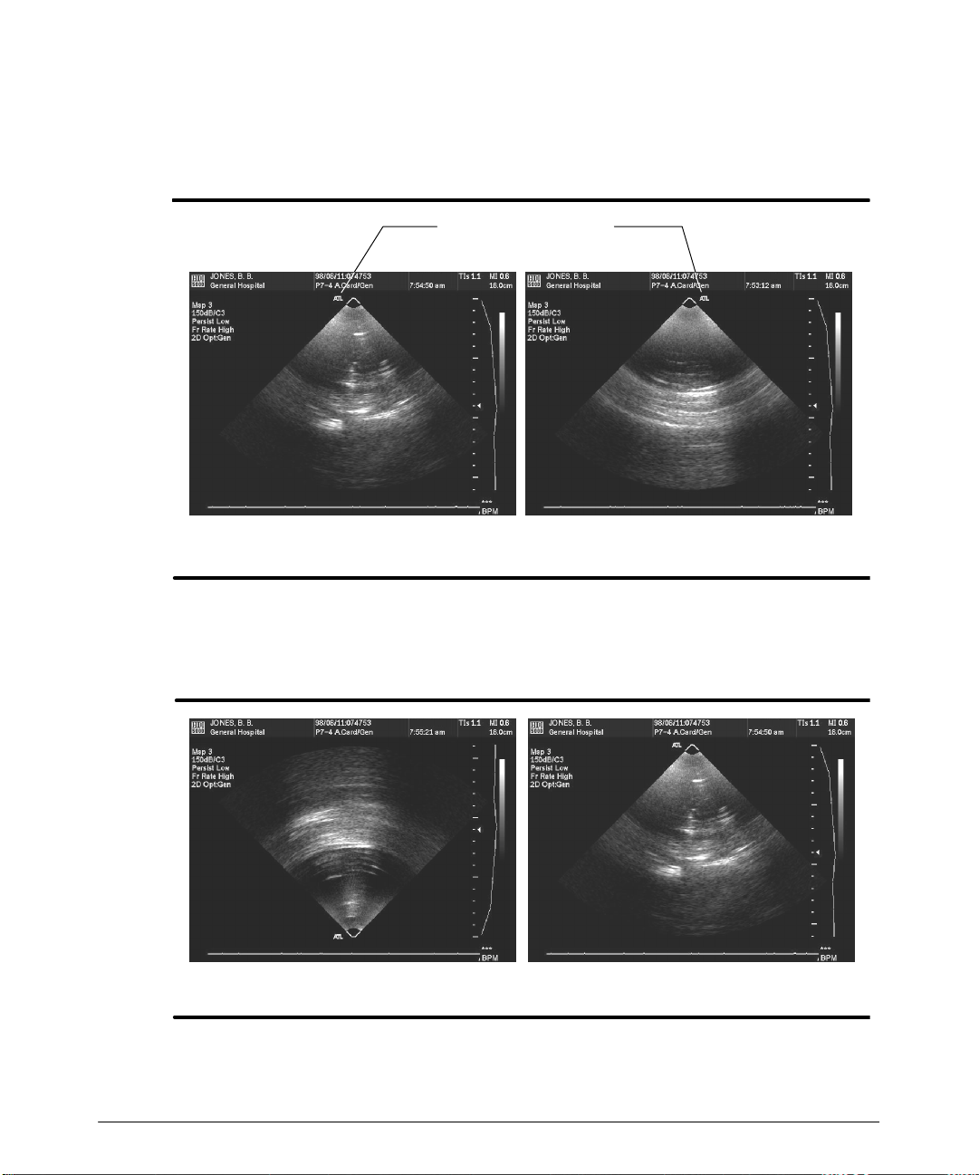
Imaging
"""" T o adjust 2D image orientation:
· Press the L/R INVERT control to alternate between left and right image orientation
(Figure 4--7).
Image left -- -- Image right --
--
Orientation marker
Figure 4--7. 2D Image Orientation (L/R INVERT)
· Press theTOP/BOT control up or down to alternatebetween skin line up and skin line
down orientations (Figure 4--8).
-- Skin line down--
Figure 4--8. 2D Image Orientation (TOP/BOT)
-- Skin line up --
4-- 8
HDI 5000 Getting Started 4708-0027-03
Page 39
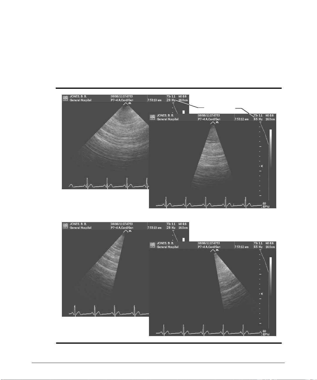
Imaging
"""" T o adjust 2D sector width and steer the 2D sector:
1. Press SEC WIDTH down to decrease the sector width (Figure 4--9). The frame rate
changes as the sector width is changed.
2. Use the trackball to steer the sector.
3. Press SEC WIDTH up to increase the sector width.
Frame rate
Sector width
Sector steering
Figure 4--9. Sector Width and Steering
HDI 5000 Getting Started 4708-0027-03
4-- 9
Page 40
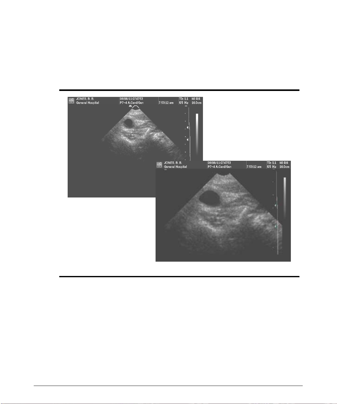
Imaging
"""" To use zoom:
1. Press the ZOOM control up to magnify the 2D image (Figure 4--10).
2. Rotate the trackball to pan the 2D image and view areas of interest.
3. Press the ZOOM control down to decrease the magnification of the 2D image.
Normal image
Zoomed image
Figure 4--10. 2D Zoom
4-- 10
HDI 5000 Getting Started 4708-0027-03
Page 41

Imaging
"""" To use HD (High Definition) Zoom:
1. During real-time 2D, M-mode, Color, Tissue Doppler (TDI), or Power imaging, press
theHD ZOOM control. The HD Zoom box appears on the2D display and defines the
r egion of int er es t ( F igur e 4 -- 11) . I n Color or P ower, t he ov er lay def ines t he r egion of
interest.
2. Use the trackball to position the HD Zoom box or overlay.
3. P r es s t he SEL ECT c ont r ol t o dis play t he t r ac k ball s elec t ion m enu ( F igur e 4 -- 11) .
4. Press the SELECT control to highlight HD Zoom Size (or Col Size).
5. Use the trackball to adjust the HD Zoom size.
6. Use the SELECT control to alternate between HD Zoom Size and Pos (or Col Size
and Pos) until you have selected the size and position that you require.
7. P r es s t he HD ZOOM c ont r ol t o f ill t he im age dis play ar ea ( F igur e 4 -- 11) . T he HD
ZOOM indicator lights.
8. Press the HD ZOOM control to turn off HD Zoom.
HDI 5000 Getting Started 4708-0027-03
4-- 11
Page 42
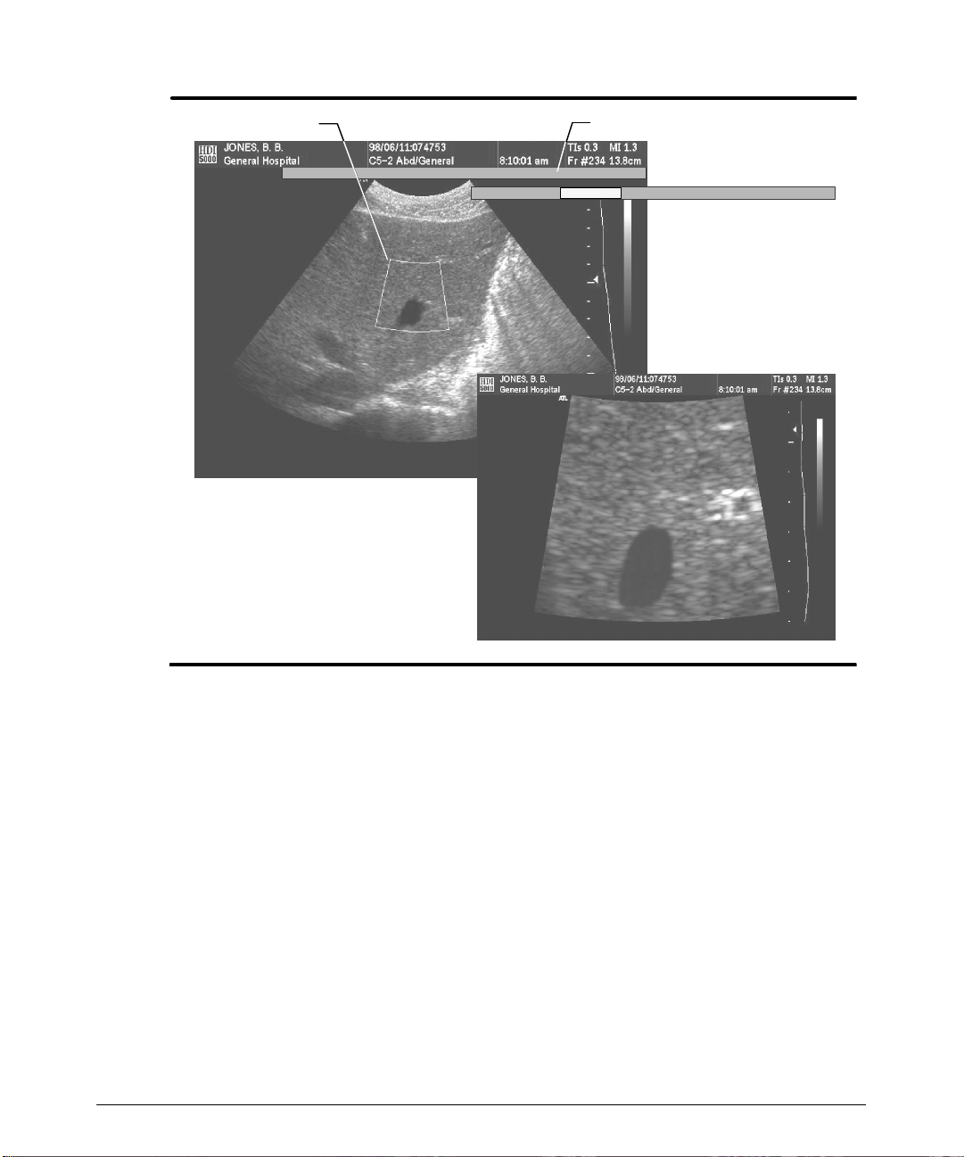
Imaging
HD Zoom promptHD Zoom box
Press HD ZOOMagain to magnifythe image.
HD Zoom Pos HD Zoom Size
Trackball menu after
pressing select
4-- 12
Zoomed image
Figure 4--11. HD Zoom
HDI 5000 Getting Started 4708-0027-03
Page 43
Imaging
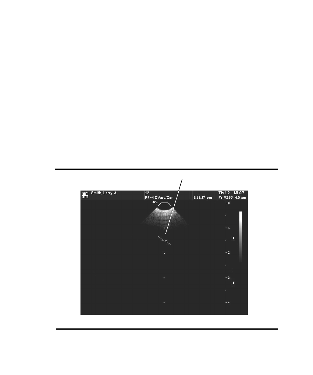
"""" T o use the CURSOR control to designate the source of a scrolling display:
1. Press the CURSOR control to display the cursor. The cursor is a dotted line that
includes a depth cursor (Figure 4--12). An angle correction cursor can be added by
pressing the ANG COR control.
2. Move the dotted-line cursor to the desired location on the 2D display. (When you
switch to ascrolling imagingmode, the scrolling imaging display willbe derived from
the selected cursor location on the 2D display.)
3. Move thedepth cursorto thedesired depth. (ADopplerimaging displaywillinvokethe
sample volume (SV) depth indicated by the depth cursor.)
4. If needed, press the ANG COR control to display and set the Doppler angle. (A Doppler imaging display will invoke the angle correction.)
5. Y oumay want to moveback and forth between2D anda scrolling imaging mode (CW
or PW Doppler or M-mode). To do this press the UPDATE control.
6. To turn off the cursor, press the CURSOR control.
Cursor, SV depth, and
angle correction
HDI 5000 Getting Started 4708-0027-03
Figure 4--12. Cursor
4-- 13
Page 44
Imaging
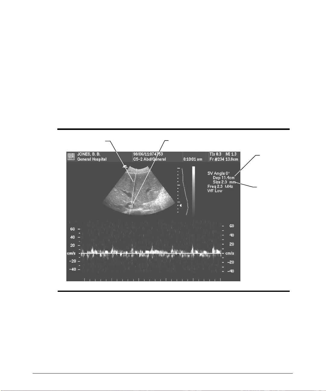
"""" To adjust the pulsed Doppler sample volume depth:
DuringpulsedDopplerimaging, usethetrackballtomove the samplevolume depthcursor
andtheD-lineasrequired(Figure 4--13). Thesamplevolumedepthannotation changes to
reflect the depth of the sample volume cursor on the 2D display.
"""" To adjust the pulsed Doppler sample volume size:
· Press theSV SIZE control up to increasethe sample volumesize. (Figure 4--13). The
SV Size value annotation on the display changes to reflect the sample volume size
selection. The TI and MI values can also change.
· Press the SV SIZE control down to decrease the sample volume size.
D-line
Sample volume cursor
Sample
volume
depth
Sample
volume
size
Figure 4--13. Sample Volume Depth and Size
4-- 14
HDI 5000 Getting Started 4708-0027-03
Page 45
Imaging
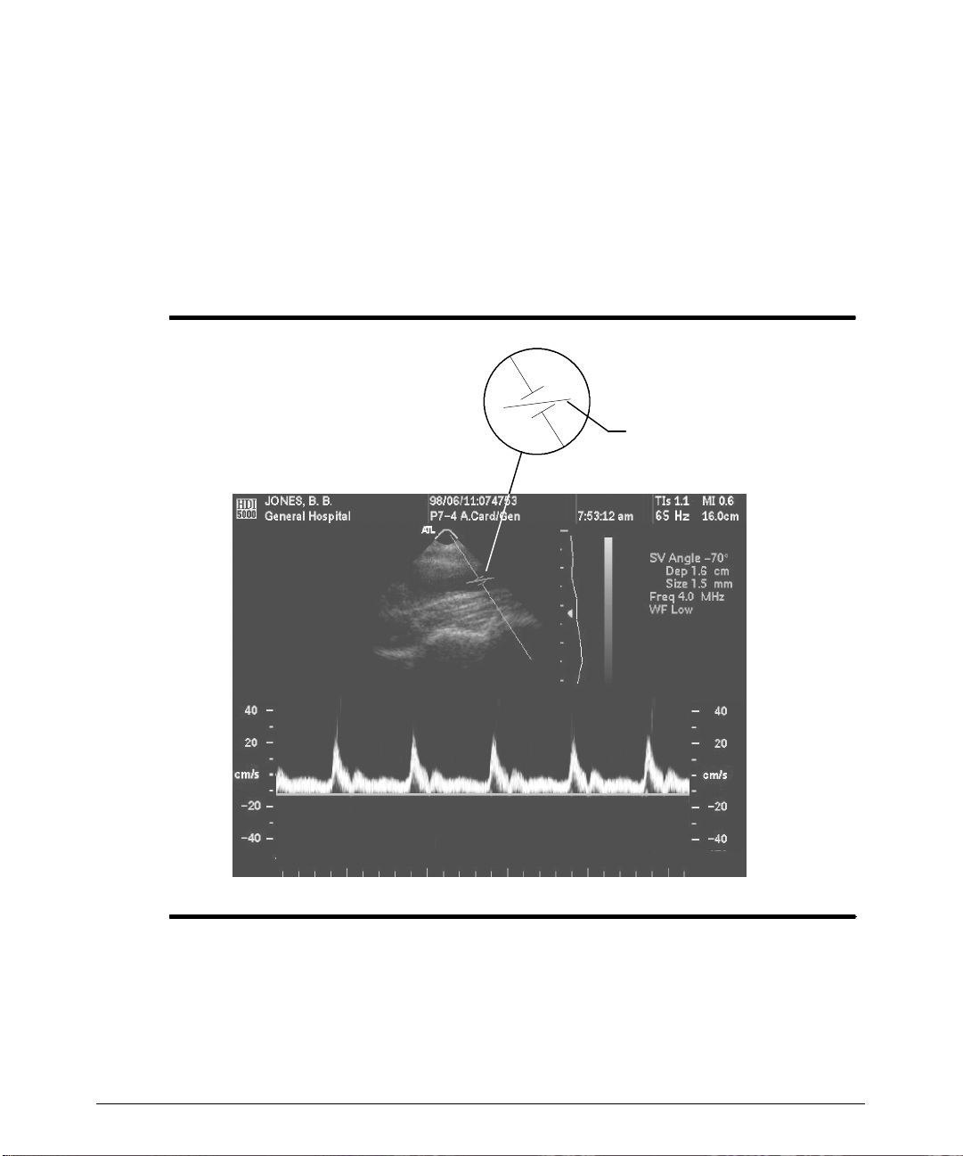
"""" T o adjust the angle correction:
The flow direction cursor rotates relative to the D-line and sample volume cursor when
ANG COR is pressed (Figure 4--14). The velocity scale is automatically corrected for the
angle depic t ed on t he 2D im age. S ee als o “ To us e t he CURS O R c ont r ol. ”
· Press the ANG COR control to correct for the Doppler angle. (Press up for clockwise
rotation of the flow direction cursor, press down for counterclockwise rotation.)
· Youcanalso use the 0/60°°°° control toquickly set theflow directioncursor atangles of 0
or ± 60 degrees, and then use the ANG COR control for finer adjustments.
Flow direction cursor
Figure 4--14. Doppler Angle Correction
HDI 5000 Getting Started 4708-0027-03
4-- 15
Page 46
Imaging
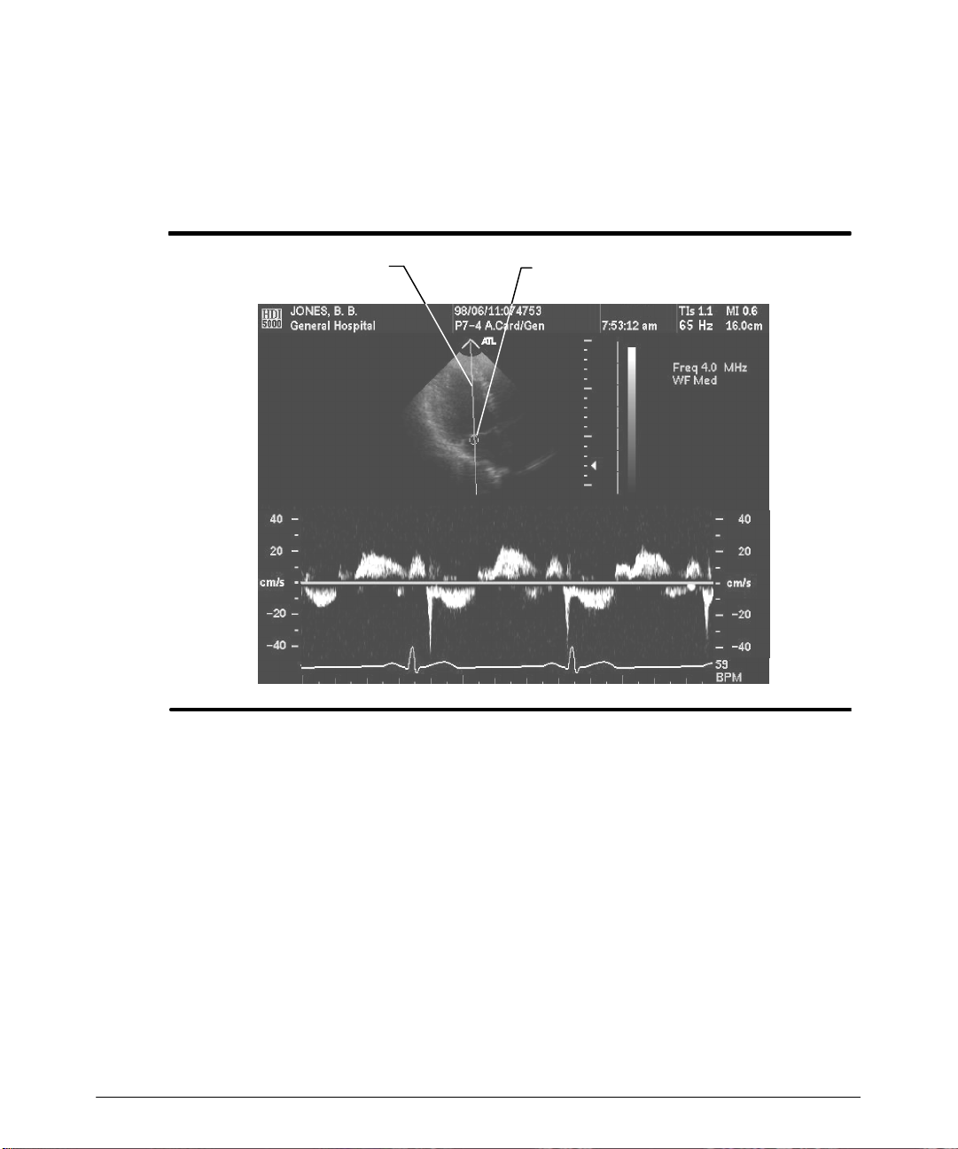
"""" To adjust the CW Doppler focus indicator:
During CW Doppler imaging, use the trackball tomove the focus indicator and the D-line
as required (Figure 4--15). The CW Doppler display does not update when the focus indicator is moving. The CW Doppler display updates after you have established the focus
indicator location.
D-line
Focus indicator
Figure 4--15. CW Doppler Focus Indicator
4-- 16
HDI 5000 Getting Started 4708-0027-03
Page 47
Imaging
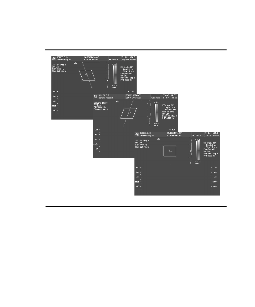
"""" T o adjust the steering angle (linear array):
Press the STEER control to change the steering angle for a linear array image
(Figure 4--16).
Initialsetting
Figure 4--16. Steering Angle (Example)
HDI 5000 Getting Started 4708-0027-03
Second setting
Third setting
4-- 17
Page 48
Imaging
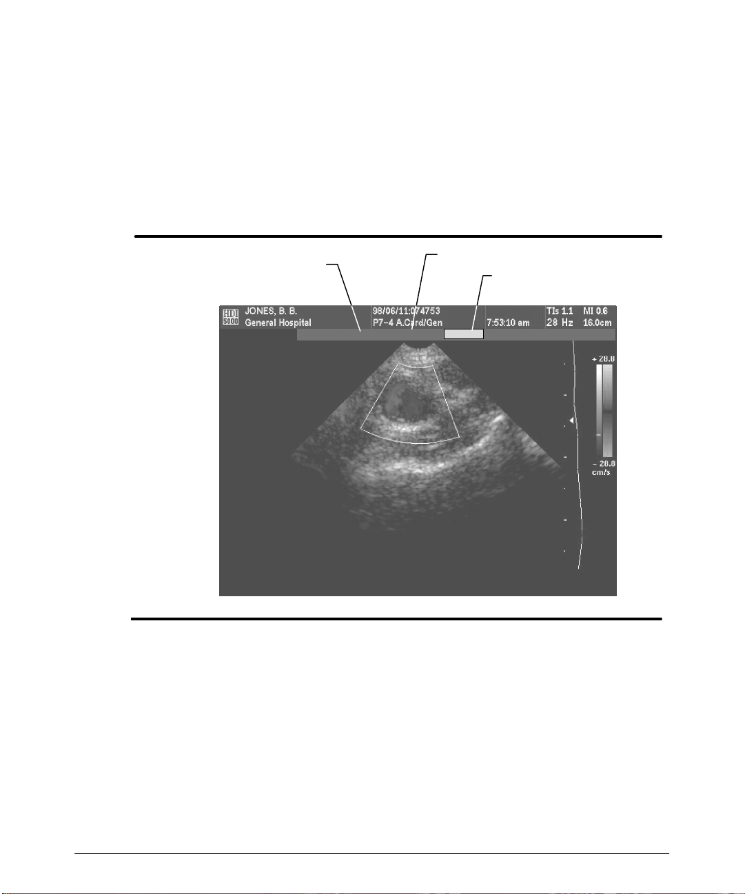
"""" T o adjust the size and position of the Color or Power overlay:
1. During Color or Power imaging, press the SELECT control to display the trackball
selectionmenu(Figure 4--17). Thetrackball selectionmenuappearsabove theimage
display for five seconds after you press the SELECT control.
2. Press the SELECT control to highlight Col Pos or Col Size.
3. Use the trackball to establishthe desiredColor overlay sizeor position: both thewidth
and the height of the Color overlay can be adjusted with the trackball.
Trackball selection menu
Col Pos
Col Size (selected)
Col SizeColPos
Figure 4--17. Color Overlay Size and Position Adjustment
"""" To invert Color or Doppler data:
Pressthe INVERT control.Thecolor bar reflectsthe change in thecolor assignments.The
Doppler spectral data inverts relative to the baseline.
"""" To adjust the Color or Doppler baseline:
· Press the BASELINE control up to raise the baseline and shift the values above and
below the baseline.
· Press the BASELINE control down to lower the baseline and shift the values above
and below the baseline.
4-- 18
HDI 5000 Getting Started 4708-0027-03
Page 49

Imaging
"""" To adjust the Doppler, Color, or Power filter:
· Press theFILTERcontrolup to increase theamount oflow frequency wall motionthat
will be filtered. (The FILTER control does not work in Tissue Doppler Imaging.)
· Press the FILTERcontrol down to decrease the amount of low frequency wall motion
that will be filtered.
"""" To adjust the Doppler, Color, or Power scale:
· P r es s t he SCALE c ont r ol up t o inc r eas e t he r ange of t he dis play. T he Ny quis t v alues ,
frame rate, and the PRF change to reflect the change, as appropriate. (High PRF is
av ailable wit h s om e s c anheads . P r es s ing t he S CAL E c ont r ol aut om at ic ally inv ok es
high PRF for these scanheads, displaying additional sample volumes.)
· P r es s t he SCALE c ont r ol down t o dec r eas e t he r ange of t he dis play. T he Ny quis t v alues, frame rate, and the PRF change to reflect the change, as appropriate.
"""" To adjust the Color or Power priority threshold:
· Press the PRIORITY control up to raise the echo amplitude threshold above which
the system will display gray scale instead of Color or Power. The write priority indicator,representedgraphically on the grayscale as ashort horizontallineacross thegray
scale, changes position to show the color/gray scale threshold.
· Press the PRIORITY control down to decrease the priority threshold.
"""" T o activate triple mode:
1. During 2D imaging, press the COLOR control. Color imaging begins.
2. Press the PULSED control. The Doppler display appears.
3. Simultaneously press the Superkey and the Simult key to activate triple mode, or
perform steps 4 through 7.
4. Press the DOPPLER MENU control. The Doppler menu appears.
5. Select 2D Update.TheUpdate menu appears.
6. Select Simul. Triple mode begins.
7. Select Close, or press the DOPPLER MENU control to remove the menu.
HDI 5000 Getting Started 4708-0027-03
4-- 19
Page 50
Imaging
"""" To display dual images:
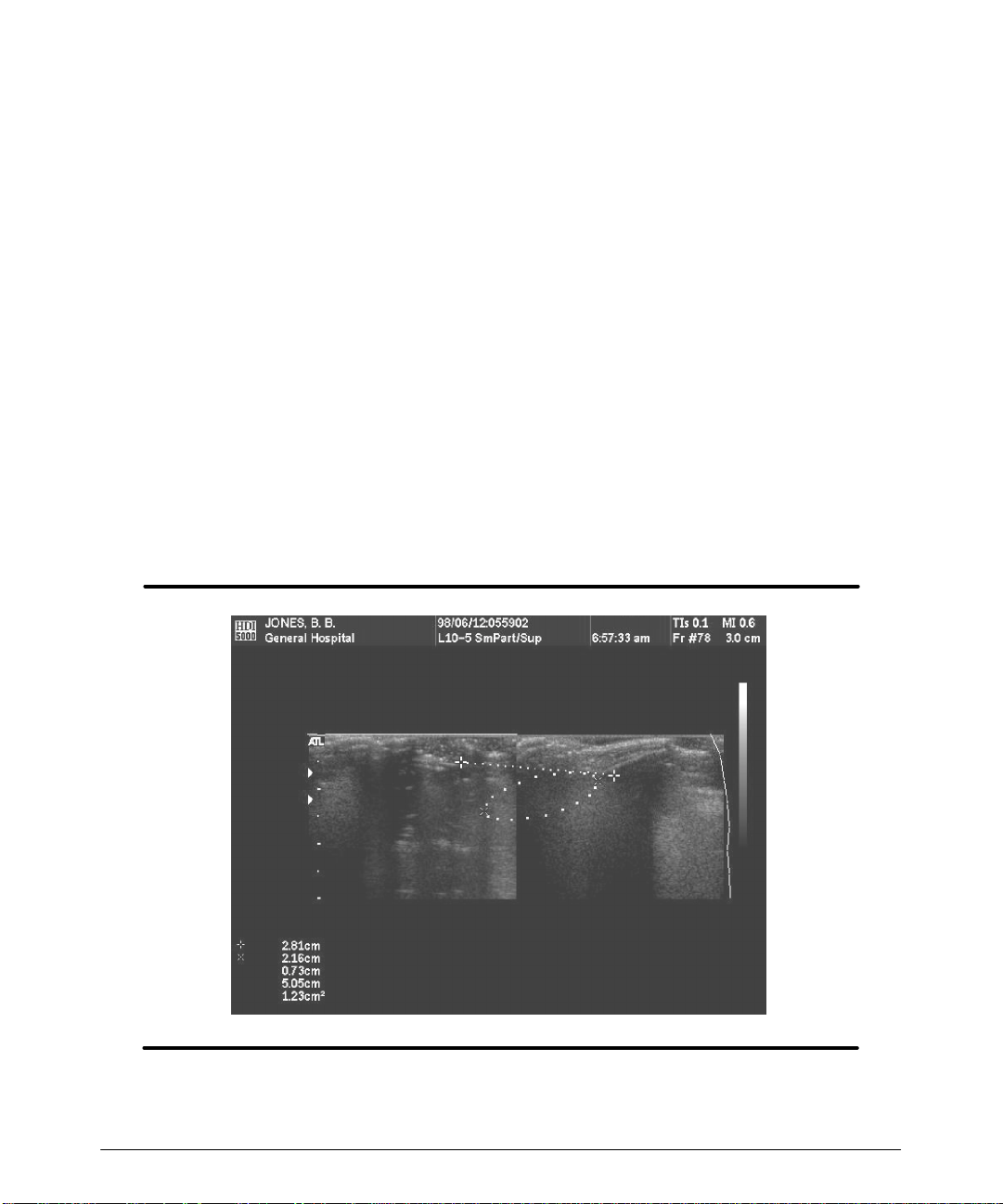
1. During 2D acquisition, press the DUAL control. The 2D imagebecomes smaller and
shifts to the left of the display screen.
2. Press UPDATE to display a second 2D image and alternate between update of images (Figure 4--18). The image on the right is now updating. The orientation marker
flashes to indicate that the image is updating.
-- The following 2D MENU controls can be used to modify both images: Chroma,
Gray Maps (GMap), 2D PRF, TIs/TIb, and Persistence.
-- FREEZE and the remaining 2D controls can be used to modify the updating
image. During freeze, Cineloop review is possible, using the trackball; the functions on the Cinelooprrrr menu are not available.
--
HD ZOOM is not available in dual imaging.
-- You can measure across dual images, if the same magnification, sector width,
and scale are in use (Figure 4--18).
3. Press the DUAL control to turn off the display of dual images and return to normal2D
imaging.
4-- 20
Figure 4--18. Dual 2D Image Display Showing
Measurements Across Images
HDI 5000 Getting Started 4708-0027-03
Page 51
Imaging
"""" To use a 2D Cineloop sequence:
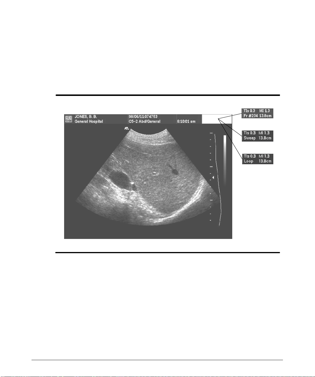
1. During 2D image acquisition, press FREEZE. The frame rate display changes to a
frame counter,reflecting the number of the currently displayed frames in the Cineloop
sequence (Figure 4--19). (When ECG is displayed, the frame counter is not displayed.)
2. Rotate the trackball to the left or to the right to move through the Cineloopsequence
selecting and displaying the frames within the Cineloop sequence.
or
or
Figure 4--19. 2D Cineloop Review
"""" Using the Cineloop Image Review controls:
1. P r es s t he 3D/CINE MENU c ont r ol t o dis play t he Cineloop rrrr m enu ( F igur e 4 -- 20) .
-- Sel e c t Play/Pause to alternate between play and pause. (You can also use the
Superkey and the Cine Playback key.)
-- Sel e c t +Speed or --Speed, while the Cineloop sequence is replaying, to vary the
speed.
-- Sel e c t Sweep/Loop to alternate between sweepand loop. Note that the type of
playback, sweep or loop, is annotated in the annotation area at the top of the display in place of the frame counter (Figure 4--19).
HDI 5000 Getting Started 4708-0027-03
4-- 21
Page 52

Imaging
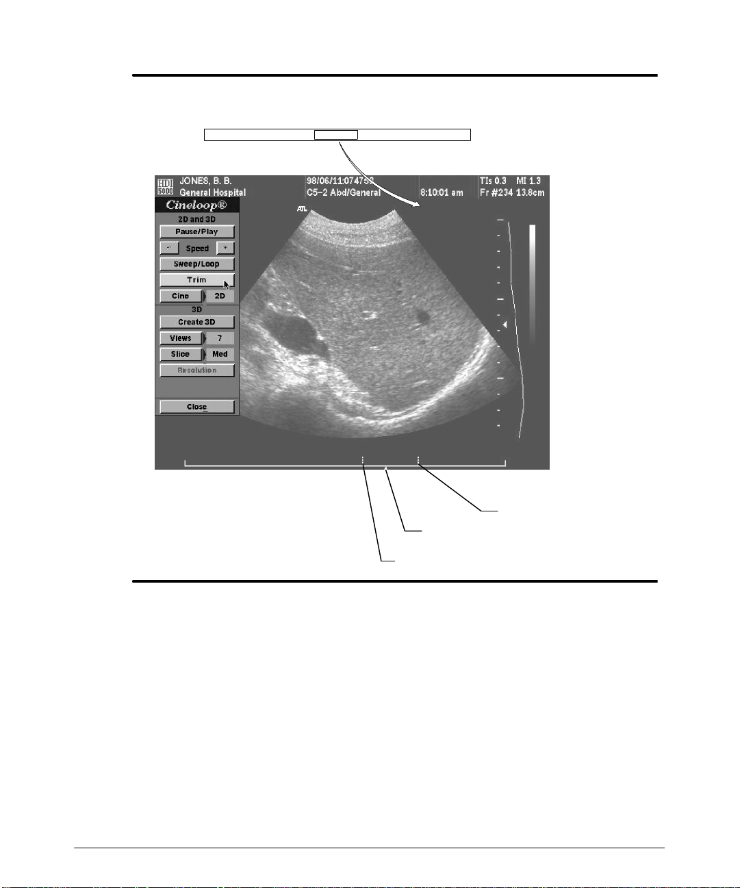
2. To play back a selected portion of the Cineloop sequence:
a. In pause, select Trim. The Cineloop graphic and trim cursors appear,and theleft
trim cursor is enabled.
b. Tr im t he Cineloop s equenc e ( F igur e 4 -- 20) .
c. Press SELECT until Trim Right is highlighted on the trackball menu, to enable
the other trim cursor.
d. Trim the Cineloop sequence.
e. Press SELECT until Cineloop Review is highlighted on the trackball menu.
f. Use thetrackballto movethe frame-selectcursor, displaying single frameswithin
the trimmed Cineloop sequence.
g. Press SELECT to switch between trim cursors and review. Use the trackball to
move the trim cursors or the frame select cursor, as desired.
h. Select Play/Pause from the Cinelooprrrr menu to play the Cineloop sequence.
3. Select Close on the Cinelooprrrr menu.
4. Press FREEZE to return to 2D imaging.
4-- 22
HDI 5000 Getting Started 4708-0027-03
Page 53
Imaging
Trackball menu (appears after selecting Trim or pressing
SELECT during trimming, disappears after 5 seconds)
TrimRight Trim Left Cineloop Review
HDI 5000 Getting Started 4708-0027-03
Right trim cursor
Frame-select cursor
Left trim cursor
Figure 4--20. Trim Cursors
4-- 23
Page 54

Imaging
"""" To use M-mode review:
1. During M-mode imaging, press the FREEZE control.
2. Review the M-mode data.
-- As you rotate the trackball to the left, the M-mode display scrolls to the right, dis-
playing the older M-mode review data.
-- As you rotate the trackball to the right, the M-mode display scrolls to the left, dis-
playing the more recently acquired M-mode review data.
3. Press the FREEZE control to return to M-mode imaging.
"""" To use Doppler review:
Note
Changing the PRF, scale, baseline, invert, display format, steer, sample volume size or
depth, or sweep speed during scrolling clears the Doppler review memory buffer. The
Doppler review memory buffer is cleared to ensure that the Doppler review data and
the display scaling correspond.
1. During active Doppler acquisition, press the FREEZE control.
2. Review the Doppler data.
-- As you rotate the trackball to the left, the spectral display scrolls to the right, dis-
playing the older Doppler review data.
-- As you rotate the trackball to the right, the spectral display scrolls to the left, dis-
playing the more recently acquired Doppler review data.
3. Press the FREEZE control to return to Doppler imaging.
4-- 24
HDI 5000 Getting Started 4708-0027-03
Page 55
Imaging
"""" T o adjust a physio display:
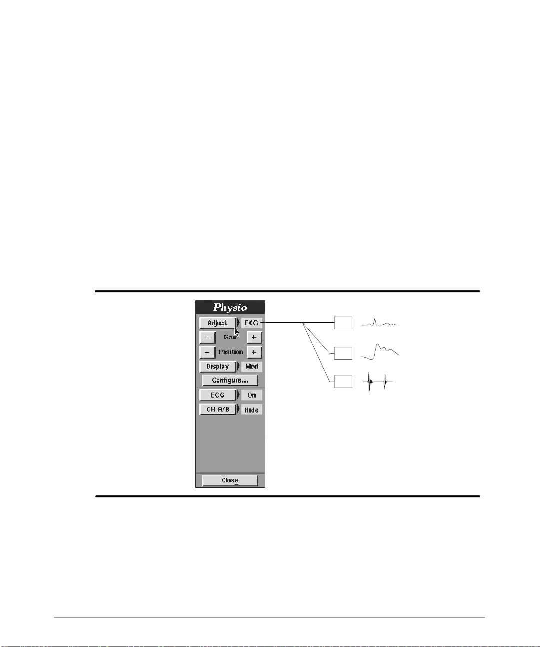
1. Press the PHYSIO MENU control to display the Physio menu (Figure 4--21).
2. Select Adjust until the physio display that you want isshown. The choices are ECG,
ChA, and ChB.
3. At this point you can adjust the gain, position, size of display, hide ChA or ChB, and
configure the display selected in step 2:
-- Sel e c t +Gainor -- Gain to adjust the gain of the physio trace. The default gain
setting is set for most patients. If the signal appears too weak, check the connections or placement of the leads or transducer before adjusting the gain setting.
-- Sel e c t + Position or -- P o s i t i o n to position the physio trace on the display.
-- Sel e c t Display to choose Small (Sm), Medium (Med), or Large(Lg). The physio
display will assume the display size that you select.
-- Sel e c t ECG to turn the ECG display On or Off.
-- Select ChA/B to chooseHide or Show.SelectingShowdisplays theChA/B phy-
sio display, Hide does not display the physio display.
ECG
ChA
Ch B
Figure 4--21. Adjusting the Physio Display
HDI 5000 Getting Started 4708-0027-03
4-- 25
Page 56

Imaging
4. When you select the Configure submenu, use the trackball and the SELECT control
to configure the channel as follows:
-- For ECG , the Triggers menu appears. (See “To configure for ECG-triggered
operation”)
-- For Channel A, select Aux (auxiliary), Pulse, or turn off Channel A.
-- For Channel B, select Aux, Phono, or turn off Channel B.
-- For Channel B, select a phono filter: Off, Low, Med (medium), or High.
"""" To configure for ECG-triggered operation:
ECG-triggeredoperation is available in 2D,Power Motion Imaging(PMI),and Color imaging,andisusedforContrastSpecificImaging (CSI).For moreinformationaboutthe useof
CS I and F las h, s ee t he “ P hy s io” s ec t ion of t he Ref er enc e M anual.
1. Press the PHYSIO MENU control to display the Physio menu.
2. Ensure the ECG display is on.
3. To adjust the ECG display, select Adjust until ECG appears.
4. If necessary, change the ECG gain and position.
5. Select Configure to display the Triggersmenu. (Youcan also press TRIGGERS to
display the Triggers menu.)
4-- 26
6. SelectTriggerType +or -- to cycle throughto yourchoice of TriggerA,TriggerB,or
A&B
.
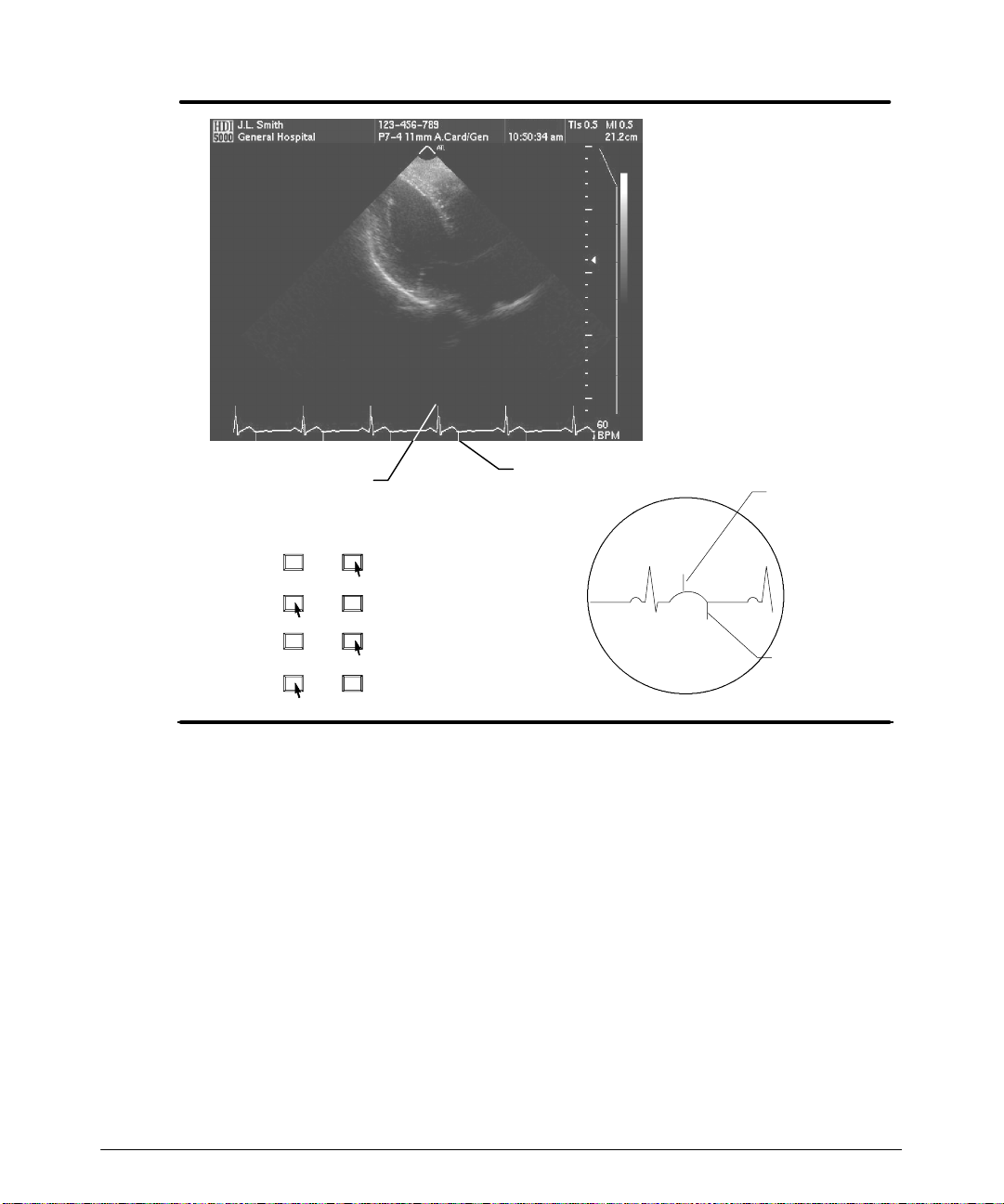
7. ,Select Delay (ms) A+ or Delay (ms) B+ to increase the delay of the ECG triggers
( F igur e 4 -- 22) .
8. Select Delay (ms) A-- or Delay (ms) B-- to decrease the delay of the ECG triggers
( F igur e 4 -- 22) .
9. Select Trigger Interval Each N + or -- to skip ECG triggers.
10. Select Frames to change the number of frames for each triggered acquisition.
11. Select Frame Interval to select adelay between frames, if there are multiple frames
for each trigger. The FR setting is the normal system frame rate.
12. To alternate between ECG-triggered acquisition and 2D imaging:
-- Press UPDATE
-- If you have a footswitch, press and release the UPDATE (middle) footswitch.
HDI 5000 Getting Started 4708-0027-03
Page 57
Imaging
Trigger A
Delay (ms)
-- +--
A:00
-- +--
-- +--
B:00
-- +--
Trigger B
moves trigger A ®
moves trigger A ¬
moves trigger B ®
moves trigger B ¬
®
¬
Figure 4--22. ECG Trigger Positioning
®
¬
Trigger A
Trigger B
HDI 5000 Getting Started 4708-0027-03
4-- 27
Page 58
Annotating the Display
The alphanumeric keys and the Title, Arrow, Home, Text, Body Marker, and SH Pos
(Scanhead Position) keys are used to annotate the display . The Set Home Superkeyis
used to set the home position of the annotation cursor.
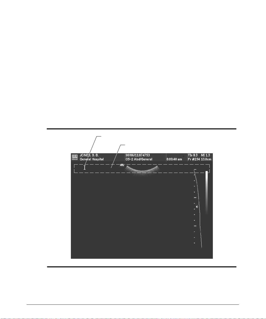
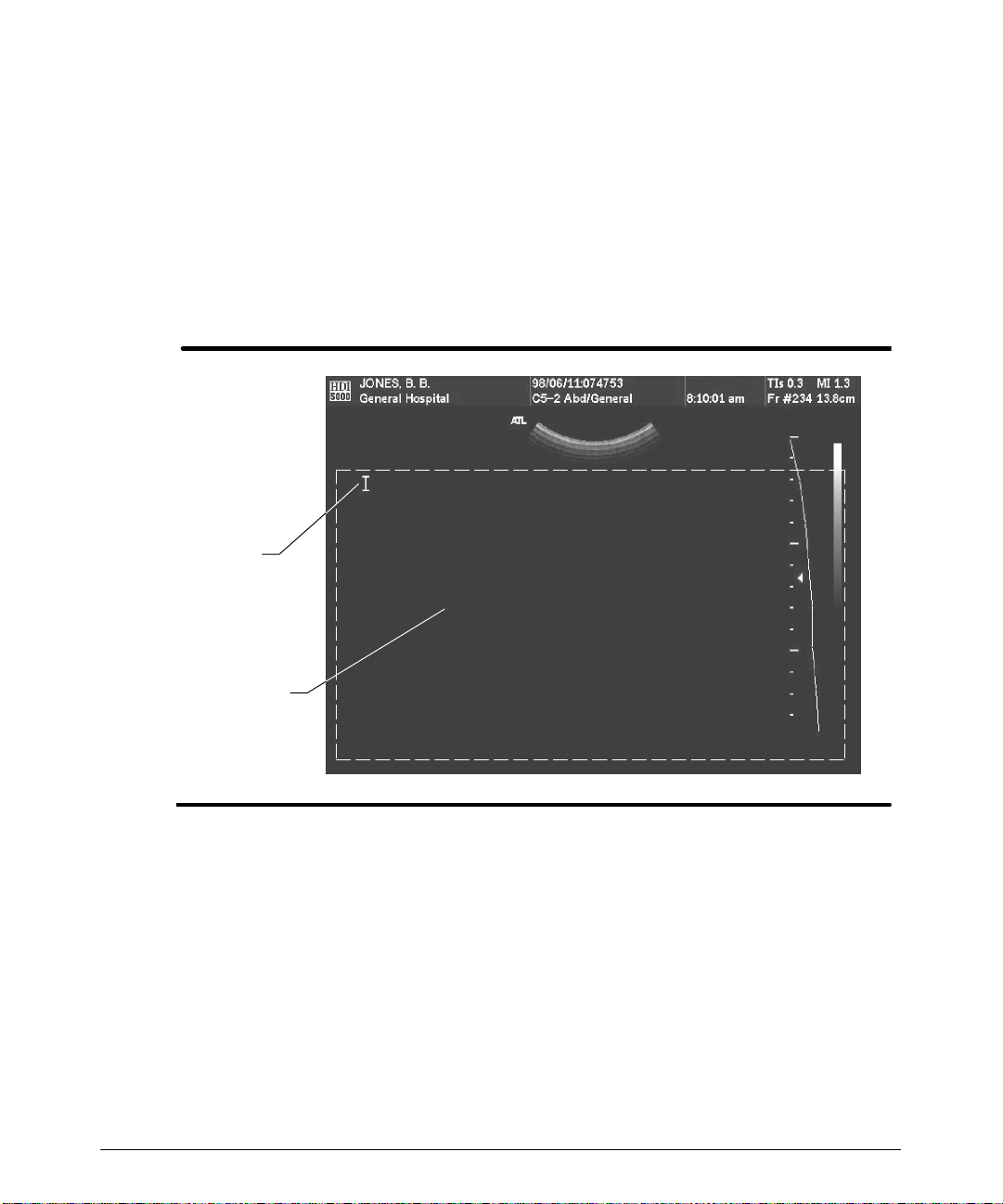
"""" To annotate with the Title key:
1. Press the Title key. A cursor apperas in the title annotation area (Figure 5--1). The
cursor can bemoved usingthe trackball, Backspace key,or thearrow keyswithin the
title annotation area.
2. Use the keyboard to enter a title in the title annotation area.
3. Press the Title key a second time to end title data entry.
Title cursor
Title annotation area
HDI 5000 Getting Started 4708-0027-03
Figure 5--1. Entering Title Annotation
5-- 1
Page 59
Annotating the Display
"""" To annotate the display with the Text key:
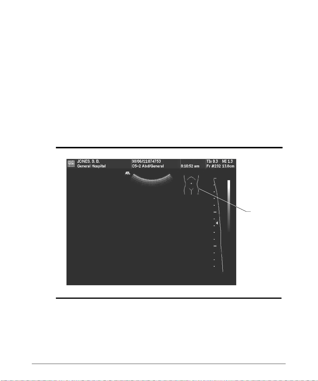
1. Press the Text key. A cursor appears in the text annotation area (Figure 5--2). The
trackball,theBackspace key,or the arrow keys can be used to move the cursor anywhere within the text annotation area.
2. Use the keyboard to enter text.
3. Press Return to continue the text on the next line.
4. Press the Text key a second time to end text data entry.
Text
cursor
5-- 2
Text
annotation
area
Figure 5--2. Entering Text Annotation
HDI 5000 Getting Started 4708-0027-03
Page 60
Annotating the Display
"""" To annotate with the Body Marker key:
Eachclinicaloption hasa set of body markers tochoosefrom, you cancyclethroughthem
by pressing the Body Markerkey.A scanhead position marker can be added toindicate
the viewing angle.
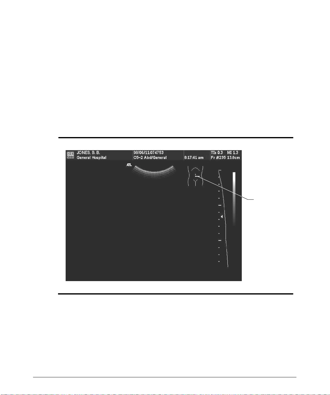
1. Press the Body Marker key. A T issue Specific body marker appears on the display (Figure 5--3).
2. Press the Body Marker key to cycle through the available body markers.
3.
Use the trackball to position the body marker on the display.
4. Press the SELECT control to anchor the body marker.
5. To remove the body marker, press the Body Markerkey until the body marker is removed.
Figure 5--3. Body Marker Annotation
"""" To annotate with the SH Pos key:
1. Press the Body Marker key, a body marker appears.
2. Press Body Marker repeatedly to cycle through the available body markers.
3. Use the trackball to position the body marker.
HDI 5000 Getting Started 4708-0027-03
Body
marker
5-- 3
Page 61
Annotating the Display
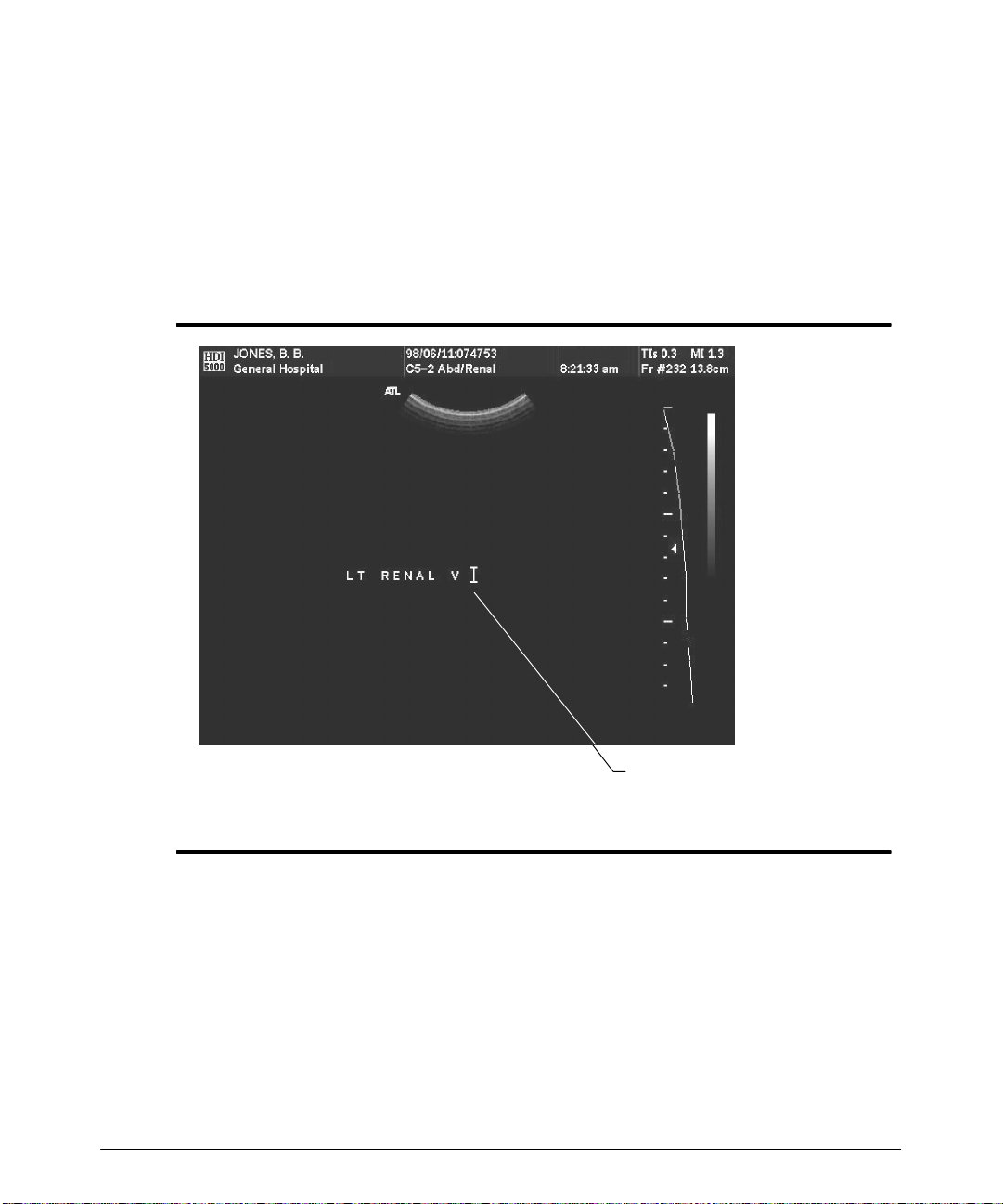
4. Simultaneously presstheSuperkeyandtheSH Poskey.Ascanheadpositionmarker
appears on the body marker (Figure 5--4).
5. Use the trackball to position the scanhead position marker on the body marker.
6. Use the arrow keysto rotatethe scanheadposition markerclockwise or counterclockwise.
7. Press the SELECT control to anchor the scanhead position marker.
8. To remove the scanhead position marker, press the Superkeyand the SH Pos key
until the scanhead position marker is removed from the body marker, or press the
Body Marker key until both the body marker and the scanhead position marker are
removed from the display.
Figure 5--4. Scanhead Position Marker
Scanhead
position
marker
5-- 4
HDI 5000 Getting Started 4708-0027-03
Page 62
Annotating the Display
"""" To display pre-defined or custom (user-defined) annotation with the TextA, B, C,
and D keys:
1. Press the Text key.
2.
Move the annotation cursor to the desired location.
3. Press the Text A, B, C,orD key to bring up initial annotation (Figure 5--5).
4. Press the Text A, B, C,orD key repeatedly to cycle through the annotations.
Figure 5--5. Using Pre-defined Annotation
HDI 5000 Getting Started 4708-0027-03
Cursor placement and initial
annotation (example from
Text D key)
5-- 5
Page 63
Annotating the Display
"""" To create annotation for the Text keys:
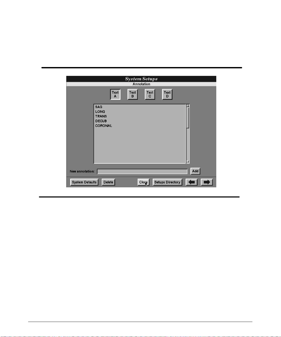
Usingthe Annotation setups,youcan createa list of terms associated withaTissueSpecific application and then assign that list to one of the four Text keys (Figure 5--6). Once
you have created the annotation and assigned it to a Text key, pressing that Text key
cycles through the terms in the list for annotation of the image display.
5-- 6
Figure 5--6. Annotation Setups
1. On the Directory of Setup Options, select Annotation.TheAnnotation setups
screen appears (Figure 5--6).
2. Select Text A, B, C,orD. A list of terms already assigned to the Text key appears in
the Annotation field.
3. Move the cursor to the New annotation field.
4. Press the SELECT control to activate text entry. The text entry cursor appears inthe
New annotation field.
5. Use the keyboard to enter the text that you want to add.
6. Select Add to add the entered term to the Annotation list.
7. Select Close.TheAnnotation setups screen is removed and imaging begins.
HDI 5000 Getting Started 4708-0027-03
Page 64

Annotating the Display
"""" To delete annotation from the Text key lists:
1. On the Directory of Setup Options, select Annotation.TheAnnotation setups
screen appears.
2. Select Text A, B, C,orD. The corresponding list appears.
3. Select the term that you want to delete.
4. Select Delete. The term is deleted from the Annotation list.
5. Select Close.TheAnnotation setups screen is removed and imaging begins.
"""" To establish a home position for the annotation cursor:
1. Press the Title key or the Text key.
2. Use the trackball to position the annotation cursor.
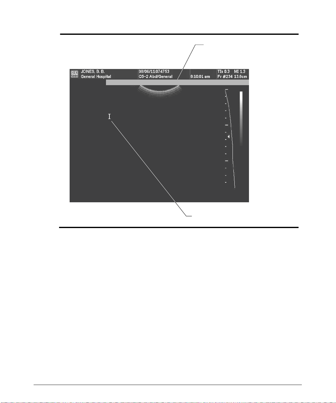
3. Press and hold theSuperkey, and then press the Set Home key.A prompt indicates
t hat t he hom e pos it ion f or t he t ex t c ur s or or t he t it le c ur s or has been s et ( F igur e 5 -- 7) .
Theannotation cursorwillappearinthenewhomepositionthe next timeyou pressthe
Title, Text,orHome key.
HDI 5000 Getting Started 4708-0027-03
5-- 7
Page 65
Annotating the Display
Prompt
(may indicate “Title” or “Text”
depending on user selection)
Textcursorhome positionhas been set.
5-- 8
Title or text cursor
Figure 5--7. Annotation Cursor Home Position Prompt
HDI 5000 Getting Started 4708-0027-03
Page 66

Annotating the Display
"""" To annotate the display with an arrow:
1. Press the Arrow key, or simultaneously press Shift and an arrow key. An arrow is
displayed.
2. Use the trackball to position the arrow. (You can display more than one arrow at a
time.)
"""" To erase annotation, perform one of the following:
· Positionthe annotationcursorto the rightoftheannotationthat you wantto erase,and
press the Backspace key.
· Position the annotation cursor to the left of the annotation that you wantto erase, and
press the spacebar.
· Press the Erase Text key to erase all text entered with the Title or Text keys.
· Press the Erase Line key to erase all text on the line with the cursor.
· Press the Erase Screen key to erase user-entered annotation from the screen.
· Press the Erase Arrow key to erase the arrows on the screen.
HDI 5000 Getting Started 4708-0027-03
5-- 9
Page 67

Making Measurements
Measurement Tools
Read t he “ M eas ur em ent s ” s ec t ion in t he Ref er enc e M anual bef or e per f or m ing t he f ollowing pr oc edur es . G uidelines in t he Ref er enc e M anual c ov er t he per f or m anc e of m eas ur ements. You should be familiar with them before performing these procedures.
Youcan measure live, frozen, or stored images. Measurement values cannot beincluded
inaprotocolunlessthe image is frozen.Asecond measurementcannot be performeduntil
the image is frozen.
Follow current medical practices when identifying specific measurement points on an
image.
Measuring 2D Images
You may want to check your setups before performing the following procedures. In the
Display setups, for 2D distance measurements, you may want to turn on the dotted line
between the cursors. In the Measurements setups, you may want to set the 2D area
method for your area measurements: Trace By Points, ContinuousTrace, and Ellipse
area methods are available. Youmay also want to set the volume method: 3 Distances,
Distance and Ellipse, and 1Distanceare available.
"""" T o perform a 2D distance measurement:
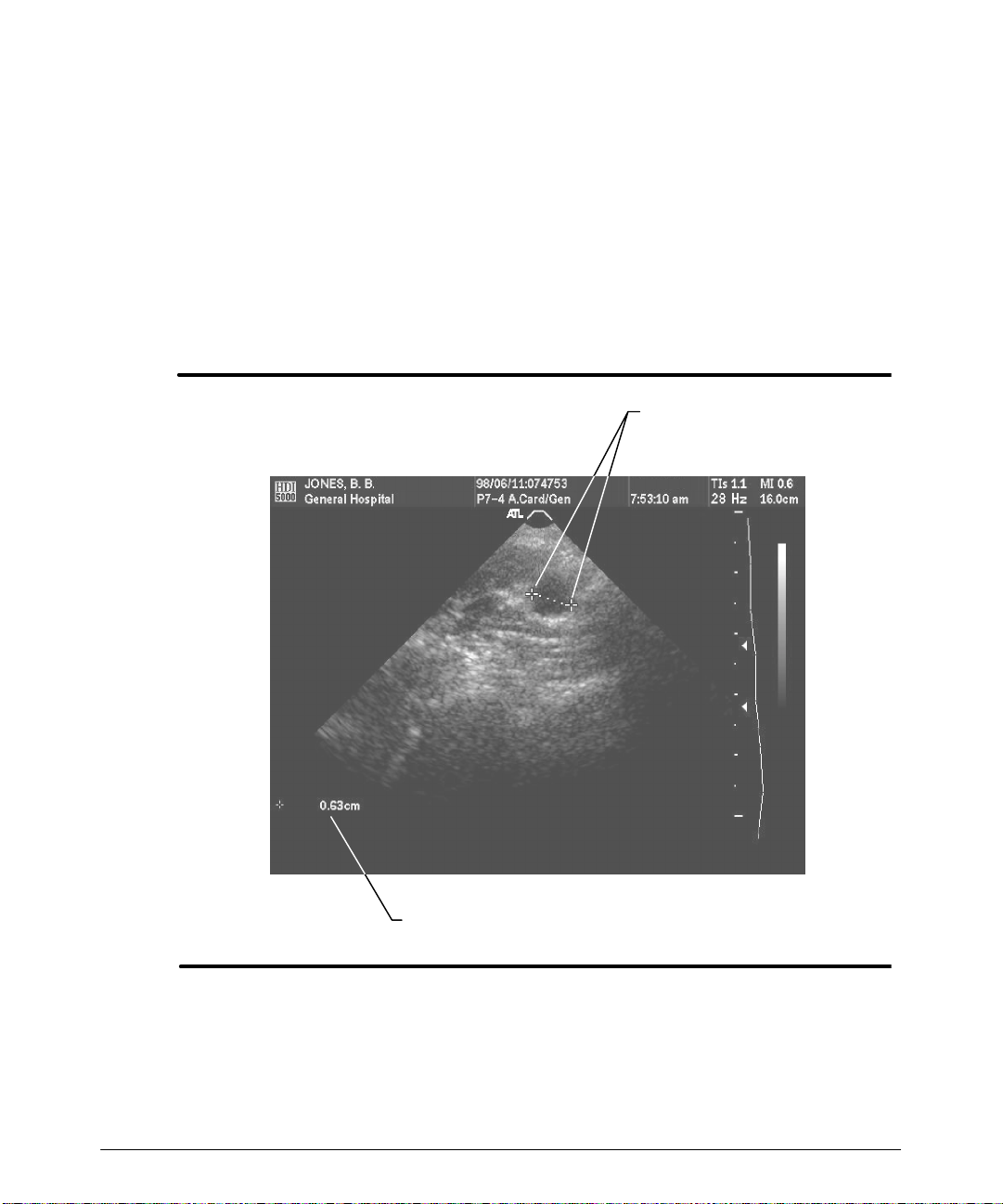
1. During 2D, Color, or Power imaging, press the DISTANCE control. A cursor appears
on the image. Initially,the results, in the lower left of the screen, contain the distance
between the cursor and the skin line.
2. Move thecursor tothe positionatwhich you wantto begin thedistance measurement.
T he dis t anc e bet ween t he c ur s or and s k in line ( ex c ept in z oom and HD z oom ) is c ontinually updated in the results.
3. Press the SELECT control. A second cursor appears, and the distance between the
two cursors is displayed in the results located in the lower left of the screen
( F igur e 6 -- 1) .
4. Move the second cursor to the desired position. The distance between the cursors is
continually updated in the results.
5. Press the SELECT control to alternate control between the two cursors, and use the
trackballto ajust thedistance between thetwocursors. Onceyouaresatisfiedwiththe
locations of the cursors, themeasurement is complete. Thedistance measurement is
displayed in the results.
HDI 5000 Getting Started 4708-0027-03
6-- 1
Page 68
Making Measurements
6. At this point you can:
-- Press the FREEZE control and then the DISTANCE control to perform and dis-
play up to six distance measurements at one time. Pressing the FREEZE control
a second time erases all measurements.
-- Press theFREEZEcontrol and then theCALCScontroltostore themeasurement
valuesinto ameasurement protocol. Pressingthe FREEZE controla secondtime
erases all measurements.
-- Press the DEL MEAS control to erase the measurement cursors and results. If
multiple measurements have been performed, pressing the DEL MEAS controla
second time will erase any remaining measurements.
Cursors
Figure 6--1. 2D Distance Measurement: Results
"""" To select a 2D area method:
You can set the default 2D area method in the Measurement setups.
1. Press the AREA control.
6-- 2
Results (distance between cursors)
HDI 5000 Getting Started 4708-0027-03
Page 69
Making Measurements
-- A cursor appears on the display.
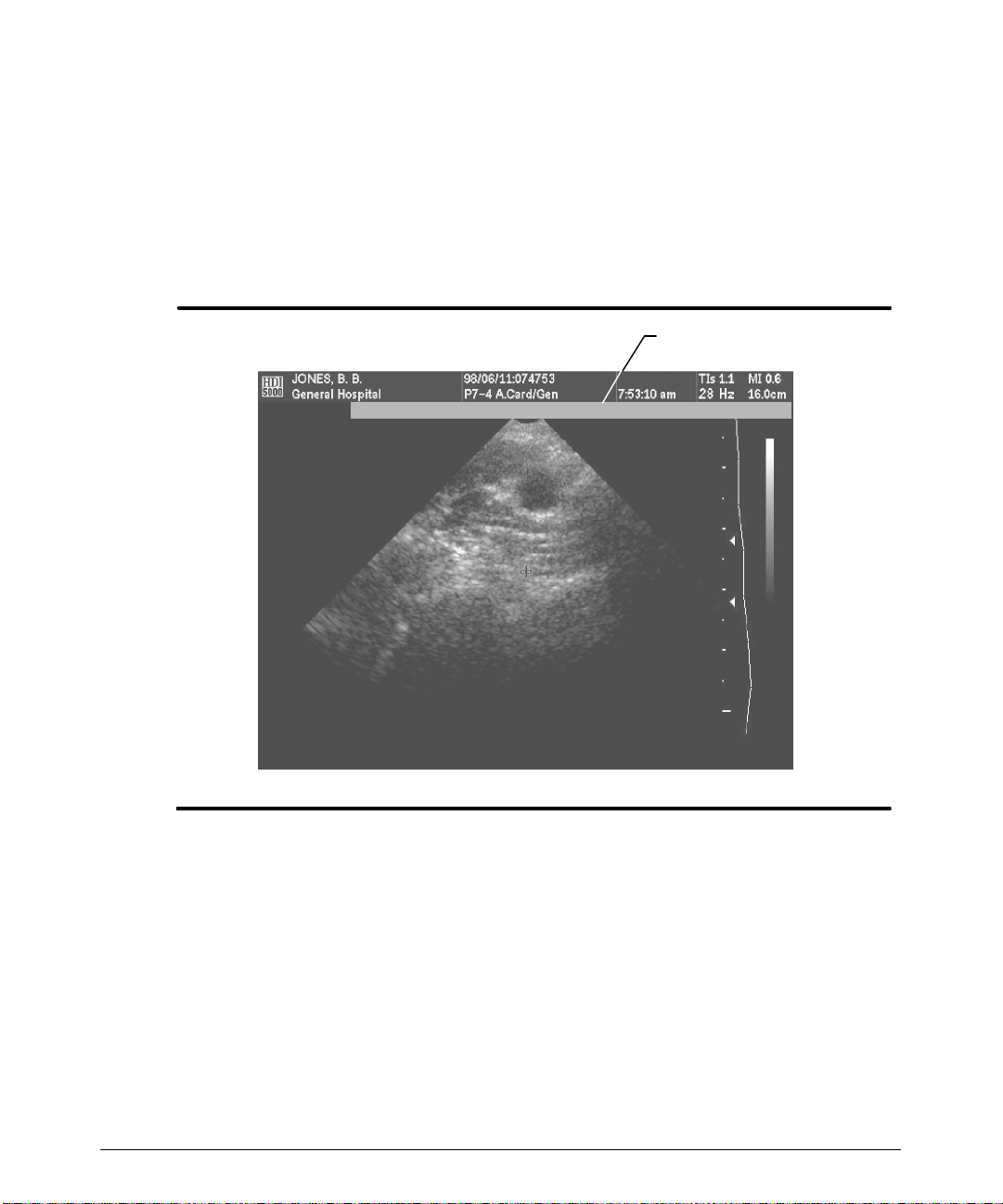
-- A 5-second prompt shows the current 2D area method (Figure 6--2).
2. To change the 2D area method, press the AREA control. Pressing the AREA control
three times cycles through the available 2D area methods: Ellipse, Continuous
Trace, and T race By Points.
3. Perform the measurement with the area method selected. See the following procedures for detailed instructions for each area method.
5-second prompt
Trace Method: Continuous Trace
Figure 6--2. 2D Area Method: 5-second Prompt
"""" To perform a 2D ellipse area measurement:
1. During 2D, Color,or Power imaging, pressthe FREEZE control. (You can measure a
live image, using the ellipse area method, but you must freeze the image before the
measurements can be stored into a measurement protocol.)
2. Press the AREA control. A cursor appears on the image.
3. Use the trackball to move the cursor to a location on the perimeter of the shape to be
measured.
4. Press the SELECT control. The first cursor is fixed and a second cursor appears. A
dotted line forms an elliptical shape based on the positions of the two cursors.
HDI 5000 Getting Started 4708-0027-03
6-- 3
Page 70
Making Measurements
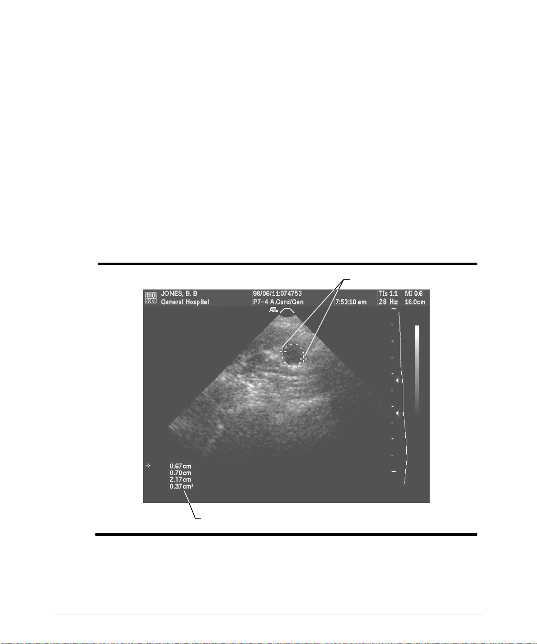
5. Usethetrackballtochangethethe length of themajoraxisandthepositionofthisaxis.
6. Press the SELECT control.
7. Use the trackball to change the width of the ellipse.
8. Use the trackball andthe SELECTcontrol to adjust the location,size and shapeofthe
ellipse. The major axis, minor axis, circumference, and area appear as results and
update as the ellipse changes shape (Figure 6--3). Once you are satisfied with the
locations of the cursors, the measurement is complete.
9. At this point you can:
-- Press the DEL MEAS control to erase the measurement cursors and results.
-- Press the AREA control to start another area measurement.
-- Press the CALCS control tostore the measurement values into a measurement
protocol.
-- Press the FREEZE control to erase the measurement and resume imaging.
Cursors
Results
Figure 6--3. Area by Ellipse
"""" To perform a 2D continuous trace area measurement:
1. During 2D, Color, or Power imaging, press the FREEZE control.
6-- 4
HDI 5000 Getting Started 4708-0027-03
Page 71

Making Measurements
2. Press the AREA control to display a cursor on the image.
3. Move the cursor to the perimeter of the shape to be measured.
4. Press the SELECTcontroltofix thepositionofthe cursoranddisplayasecond cursor.
(The second cursor will be visible once you move the trackball.)
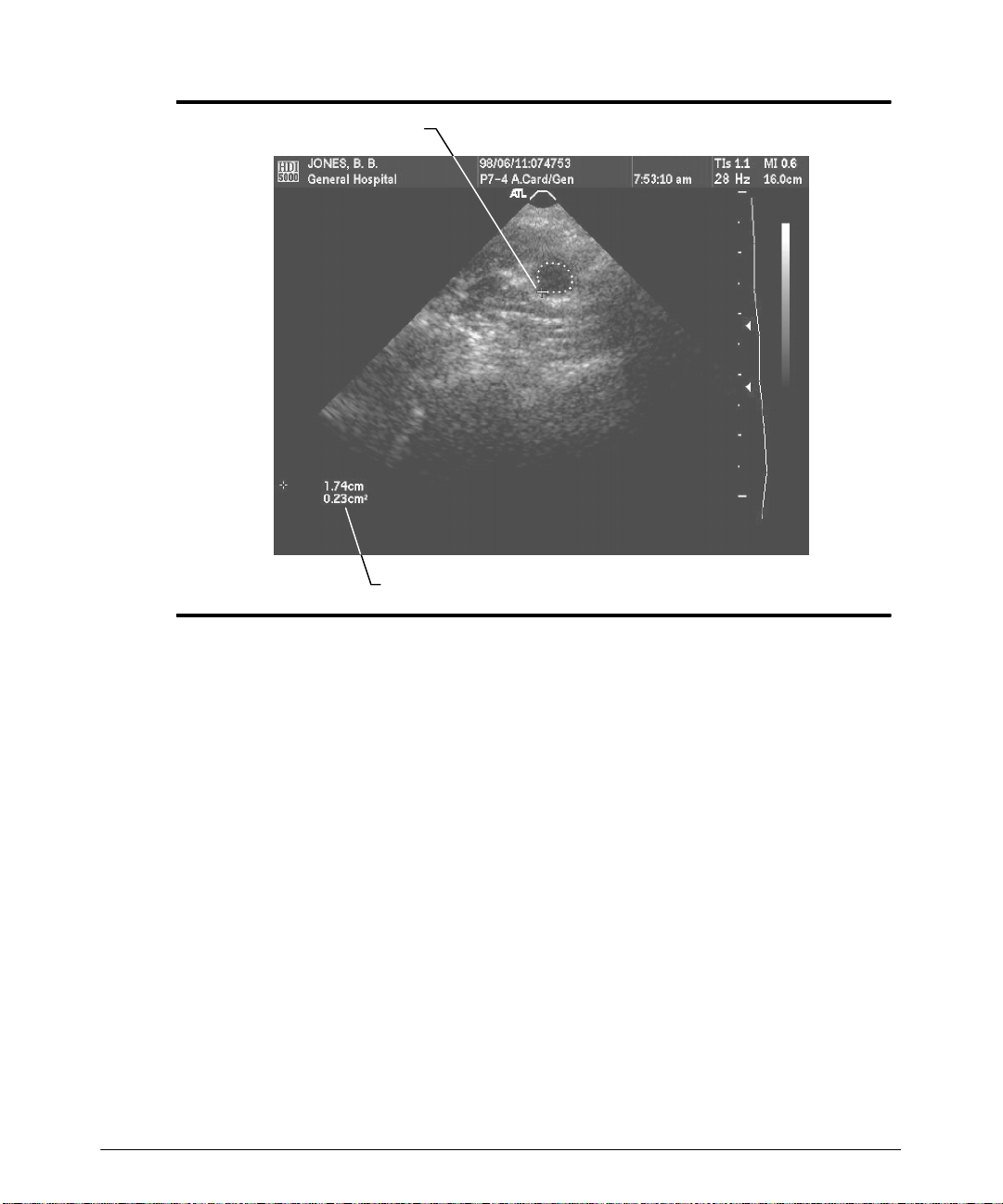
5. Move thesecond cursoraround the shape. As you move the cursor with the trackball,
t he s hape is t r ac ed on t he dis play ( F igur e 6 -- 4) .
6. If required, pressthe DEL MEAS control to erase the last segment or segmentsof the
trace.
7. Use the trackball to finish the trace near the initial cursor.
8. Press the AREA control to close the trace. The area and circumference measurement values are displayed in the results.
9. At this point you can:
-- Press theCALCS control to store the measurement values into a patient report.
(If you press the CALCS control before closing the trace, then the trace closes
and the CALCS menu appears.)
-- Press the AREA control to perform and display another continuous trace mea-
surement. (You can display three area measurements at one time.)
-- Press the DEL MEAS control to erase the measurement cursors and results.
-- Press the FREEZE control to erase the measurement and resume imaging.
HDI 5000 Getting Started 4708-0027-03
6-- 5
Page 72
Making Measurements
Cursor
Results
Figure 6--4. Area by Continuous Trace
"""" T o perform a 2D trace-by-points area measurement:
1. During 2D, Color, or Power imaging, press the FREEZE control.
2. Press the AREA control. A cursor appears on the image display.
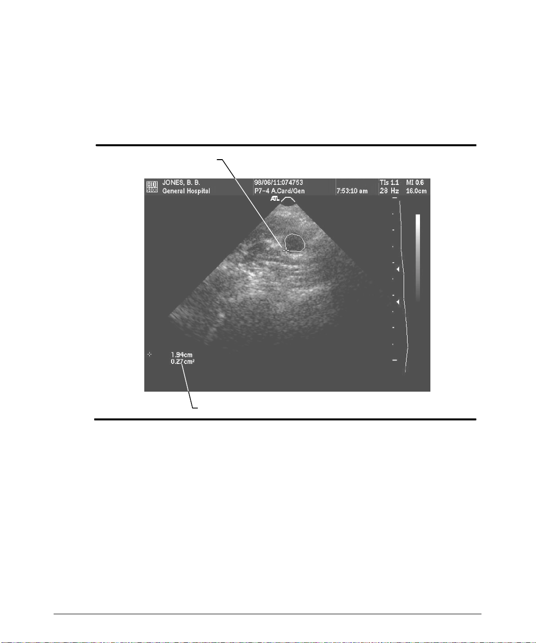
3. M ov e t he c ur s or t o t he per im et er of t he s hape t o be m eas ur ed ( F igur e 6 -- 5) .
4. Press the SELECTcontroltofix thepositionofthe cursoranddisplayasecond cursor.
5. Move the cursor to the next point on the perimeter.
6. Press the SELECT control. A straight line is drawn between the two points.
7. Repeat steps 5 and 6 until the perimeter is traced.
8. If required, press DEL MEAS to erase the last segment or segments of the trace.
9. Press the AREAcontroltoclose thetrace.The areaandcircumferencemeasurement
values are displayed in the results.
10. At this point you can:
-- Press the DEL MEAS control to erase the measurement cursors and results.
6-- 6
HDI 5000 Getting Started 4708-0027-03
Page 73
Making Measurements
-- Press the AREAcontrol to performanddisplay another trace-by-pointsmeasure-
ment. (You can display three area measurements at one time.)
-- Press theCALCS control to store the measurement values into a patient report.
(If you press the CALCS control before closing the trace, then the trace closes
and the CALCS menu appears.)
-- Press the FREEZE control to erase the measurement and resume imaging.
Cursor
Results
Figure 6--5. Area by Trace by Points
"""" T o perform a 2D volume measurement:
1. During 2D, Color, or Power imaging, obtain the image that you want to measure.
2. Press the FREEZE control.
3. Press the ADV MEAS control. The Meas Tools menu appears on the display.
4. If you have not selected avolume method in Measurements setups, or you want to
change the volume method, do so at this time.
Note
If you decide to change the volume method from the Meas Tools menu, using Vol
Method, the volume measurement will be initiated when you make your volume measurement select ion; in t his case, proceed t o st ep 6.
HDI 5000 Getting Started 4708-0027-03
6-- 7
Page 74
Making Measurements
5. Select Volume on the Meas Tools menu. The system prompts you tomake thenumber and types of measurements required by the volume method that you have
selected.
6. Use the trackball, the AREA, DISTANCE, DEL MEAS, and the SELECT controls to
perform the measurements required for the volume method selected.
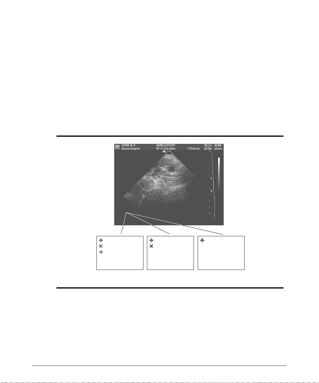
7. The results of eachmeasurementand theresults of thevolume calculationwill be displayed when you have performed the required measurements (Figure 6--6).
8. At this point you can:
-- Press the CALCS control to store the measurements into a patient report.
-- Press the DEL MEAS control to erase the measurement cursors and results.
-- Press the FREEZE control to erase the measurements and resume imaging.
6-- 8
XX.XXcm
XX.XXcm
XX.XXcm
XXX.XXccVol
XX.XXcm
XX.XXcm
XX.XXcm
XXX.XXccVol
XX.XXcm
XXX.XXccVol
1 Distance1 Dist/1 Ellipse3 Distances
Figure 6--6. 2D Volume Measurement: Results (All methods shown)
Measuring M-Mode Distance
Duringan M-modemeasurement,the measurement cursors may be movedto the2D display, and a 2D distance measurement can be performed.
To ensuredisplay integrityfor analysis andmeasurement, the M-mode displayscale must
correspond to the M-mode data display .Forthis reason, theM-mode display data isauto-
HDI 5000 Getting Started 4708-0027-03
Page 75

Making Measurements
matically cleared from the screen whenever certain control settings are changed. Similarly, the M-mode review memory buffer is cleared.
HDI 5000 Getting Started 4708-0027-03
6-- 9
Page 76
Making Measurements
"""" T o measure distance on an M-mode trace:
1. Obtain the desired M-mode display.
2. Press the FREEZE control.
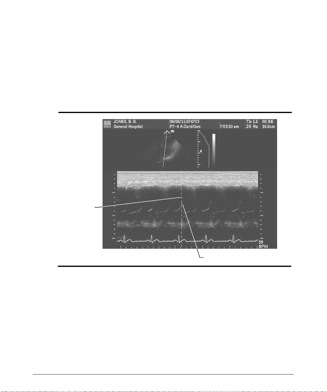
3. Press the DISTANCE control. A vertical time line and a horizontal cursor appear on
the M-mode display (Figure 6--7).
4. Use the trackball to move the timelineandthe cursorto the positionat which youwant
to begin the distance measurement. (Moving the trackball up and down moves the
cursor; moving the trackball side-to-side moves the time line.)
Vertical
time line
Horizontal cursor
Figure 6--7. M-Mode Distance Measurement
5. Press the SELECT control. A second horizontal cursor appears on the time line, and
the time line disappears. The distance between the two cursors is displayed in the
results.
6. Move the second cursor to the desired position. The distance between the cursors is
continually updated in the results.
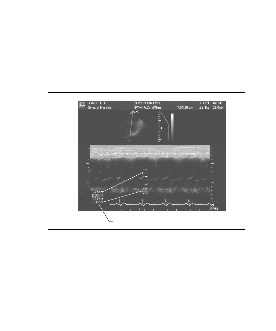
7. Toperform up to six measurementsalong thesame timeline, pressthe SELECTcont r ol t o dis play addit ional c ur s or s , and us e t he t r ac k ball t o pos it ion t hem ( F igur e 6 -- 8) .
6-- 10
HDI 5000 Getting Started 4708-0027-03
Page 77
Making Measurements
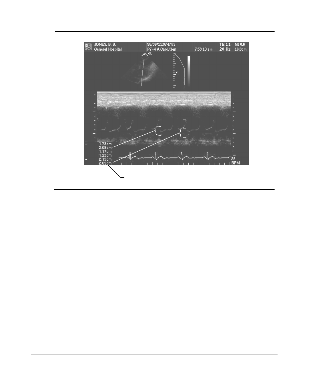
8. To perform up to six measurements along different time lines, press the DISTANCE
control todisplay successive timelines, and use thetrackball andSELECT to position
thetimelinecursors (Figure6--9).
9. At this point you can:
-- Press the DEL MEAS control to erase individual measurement cursors and
results until all are erased.
-- Press theCALCS control to store the measurement values into a patient report.
-- Press the FREEZE control to erase the measurement and resume imaging.
Figure 6--8. Multiple M-Mode Distance Measurements: Same Time Line
HDI 5000 Getting Started 4708-0027-03
Results
6-- 11
Page 78
Making Measurements
Results
6-- 12
Figure 6--9. Multiple M-Mode Distance Measurements: Different Time Lines
HDI 5000 Getting Started 4708-0027-03
Page 79

Making Measurements
Measuring Doppler Distance
You may want to check your Measurements setups before performing the following pro-
cedures.Youmay want tosetthe Doppler areamethodforyourareameasurements: Con-
tinuous Trace and Trace By Points are available. You will want to set your Doppler
Results Display in the Measurements setups.
To ensure display integrity for analysis and measurement, the Dopplerdisplay scale must
correspond to the Doppler datadisplay. For thisreason, theDoppler display data is automatically cleared from the screen whenever certain control settings are changed. Similarly, the Doppler review memory buffer is cleared.
"""" To perform a Doppler distance measurement on a live Doppler display:
1. Obtain the desired Doppler display.
2. Press theDISTANCEcontrol todisplay the measurement cursor(a dashed horizontal
line) par allel t o t he bas eline ( F igur e 6 -- 10) .
3. Use the trackball to move the measurement cursor up or down. The line provides a
way to more easily determine velocity or frequency values relative to the Doppler
scale. (Results are not displayed.)
4. At this point you can:
-- Press the DEL MEAS control to remove the measurement cursor.
-- Press theFREEZE control and perform measurements on a frozen Doppler dis-
play. Ref er t o “ To per f or m a Doppler dis t anc e m eas ur em ent on a f r oz en Doppler
display. ”
HDI 5000 Getting Started 4708-0027-03
6-- 13
Page 80
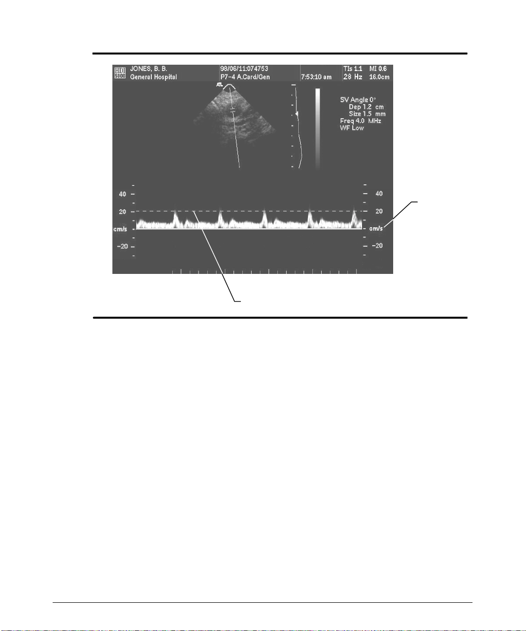
Making Measurements
Doppler
scale
Measurement cursor
Figure 6--10. Doppler Distance Measurement: Live Doppler Display
"""" To perform a Doppler distance measurement on a frozen Doppler display:
1. If you have not already done so, obtain the desired Doppler display.
2. If you have not already done so, press the FREEZE control.
3. Press the DISTANCE control to display a measurement cursor and results. The
resultscontain thedistancebetween thecursor and theDopplerbaseline in frequency
or velocity units.
4. Use the trackball to move the measurement cursor. The velocity or frequency results
are continually updated. (Youcan also move the cursor into the 2D display and perform a 2D distance measurement at this point.)
6-- 14
HDI 5000 Getting Started 4708-0027-03
Page 81
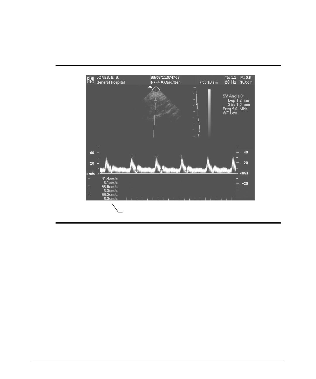
Making Measurements
5. Press the SELECT control to display the second measurement cursor of a pair of
measurement cursors (Figure 6--11).The results now contain the velocity or frequency values of the two cursors relative to the baseline and any relevant Dopplerdisplay
results.
Figure 6--11. Doppler Distance Measurement: Showing Pairs of Cursors
6. Use the trackball to move the second measurement cursor.
7. Press the SELECTcontroltoalternatecontrolbetween the cursors,andusethetrackball to adjust the positions of the cursors.
8. Onceyou are satisfiedwiththe locationsofthecursors, themeasurementiscomplete.
The velocity or frequency values of the two cursors relative to the baseline and any
Doppler display results are included in the results.
9. At this point you can:
-- Press the FREEZE control to end the measurement, remove the measurement
cursors and results, and resume live Doppler imaging.
-- Press the DISTANCEcontrolto display a different initial cursor ofa pair of associ-
at ed s ingle c ur s or s ( F igur e 6 -- 12) .
HDI 5000 Getting Started 4708-0027-03
Results
(Frozen Display)
6-- 15
Page 82
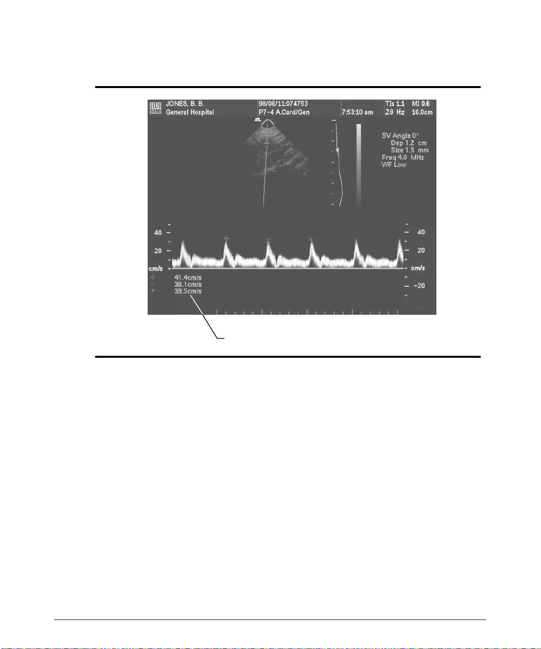
Making Measurements
-- Press the DEL MEAS control to erase the last measurement, and press theDEL
MEAS control again to delete all measurements.
6-- 16
Results
Figure 6--12. Doppler Distance Measurement: Single Cursors (Frozen Display)
HDI 5000 Getting Started 4708-0027-03
Page 83
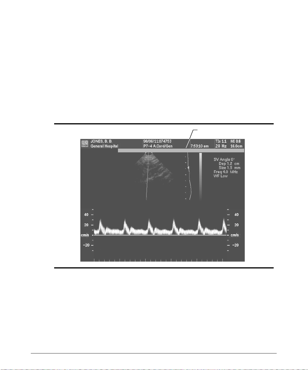
Making Measurements
"""" To select a Doppler area method:
For General Imaging clinical options, the Doppler area method is selected in the Display
setups. For Cardiology clinical options, perform the following.
1. Press the AREA control.
-- A cursor appears on the display.
-- A 5-second prompt shows the current Doppler area method (Figure 6--13).
2. Tochangethe Doppler areamethod, pressthe AREAcontrol toalternate betweenthe
two Doppler area methods: Continuous Trace and Trace By Points.
3. Perform the measurement with the area method selected. See the following procedures for detailed instructions for each area method.
5-second prompt
Trace Method: Continuous Trace
Figure 6--13. Doppler Area Method: 5-second Prompt
HDI 5000 Getting Started 4708-0027-03
6-- 17
Page 84

Making Measurements
"""" To perform a Doppler continuous trace area measurement:
1. Obtain the desired Doppler display.
2. Press the FREEZE control.
Note
If you press the AREA control, before pressing the FREEZE control, a dashed horizontal line appears along and parallel to the baseline. You can use the trackball to
move this line up and down. The line provides a way to more easily determine velocity
or frequency values relative to the Doppler scale.
3. Press the AREA control. A cursor appears on the Doppler display, and a prompt
appears above the 2D display.
4. Use the trackball to move the cursor to the start of the Doppler measurement.
5. Press the SELECT control to start the measurement and to display a second cursor.
6. Use the trackball to move the second cursor along the Doppler display to trace the
Doppler waveform.
7. If required, press DEL MEAS to erase the last segment or segments of the trace.
8. When the last point on the Doppler waveform has been traced, pressthe AREA cont r ol ( F igur e 6 -- 14) t o dis play t he r es ult s . T he v alues dis play ed depend upon t he r es ult s
selected in the Doppler Results Display in the Measurements setups.
9. At this point you can:
-- Press the AREA control to perform another continuous trace measurement.
(Only one area measurement can be displayed at one time.)
-- Press theCALCS control to store the measurement values into a patient report.
(If you press the CALCS control before closing the trace, then the trace closes
and the CALCS menu appears.)
-- Press the FREEZE control to erase the measurement and resume imaging.
-- Press the DEL MEAS control to erase the measurement cursors and results.
6-- 18
HDI 5000 Getting Started 4708-0027-03
Page 85
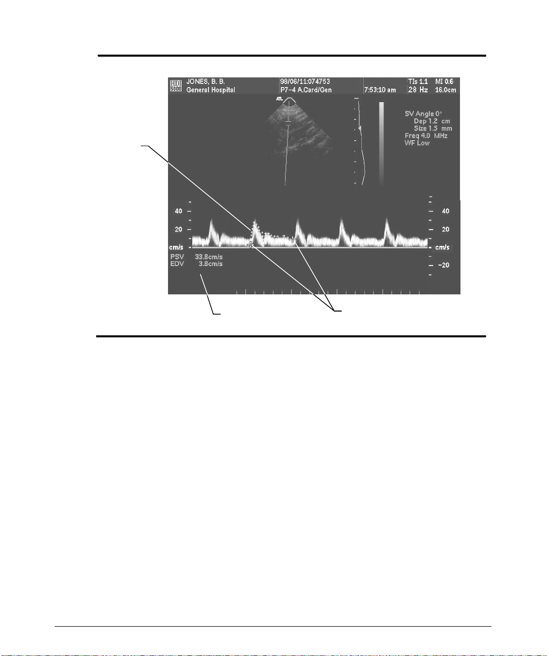
Making Measurements
Trace
Results
Figure 6--14. Doppler Area: Continuous Trace Results
"""" To perform a Doppler trace-by-points area measurement:
1. Obtain the desired Doppler display.
2. Press the FREEZE control.
Note
If you press the AREA control, before pressing the FREEZE control, a dashed horizontal line appears along and parallel to the baseline. You can use the trackball to
move this line up and down. The line provides a way to more easily determine velocity
or frequency values relative to the Doppler scale.
3. Press the AREA control to display a cursor on the Doppler.
4. Use the trackball to move the cursor to the start of the measurement.
5. Press the SELECTcontroltofix thepositionofthe cursoranddisplayasecond cursor.
6. Use the trackball to move the cursor to the next point on the Doppler waveform.
7. Press the SELECT control. A straight line is drawn between the two points.
8. Repeat steps 6 and 7 until the Doppler waveform is traced. Ensure that you end your
trace at the onset of systole.
Cursors
HDI 5000 Getting Started 4708-0027-03
6-- 19
Page 86
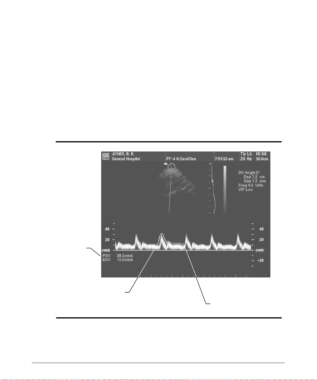
Making Measurements
9. If required, press DEL MEAS to erase the last segment of the trace.
10. Whenthe last point on theDoppler display has been marked, pressthe AREA control
to display the results. The values displayeddepend upon the parameters selected in
the Doppler Results Display in the Measurements setups (Figure 6--15).
1 1. At this point you can:
-- Press theAREA control twice to perform another trace-by-points measurement.
(Only one area measurement can be displayed at one time.)
-- Press theCALCS control to store the measurement values into a patient report.
(If you press the CALCS control before closing the trace, then the trace closes
and the CALCS menu appears.)
-- Press the FREEZE control to erase the measurement and resume imaging.
-- Press the DEL MEAS control to erase the measurement cursors and results.
6-- 20
Results
Startoftrace
End of trace
Figure 6--15. Doppler Area: Trace-by-Points Results
HDI 5000 Getting Started 4708-0027-03
Page 87

Making Measurements
Measuring Time/Slope
"""" T o perform a time/slope measurement:
1. Acquire the scrolling display that you want to measure.
2. Press the FREEZE control.
3. Press the ADV MEAS control to display the Meas Tools menu.
4. Select Time/Slope on the Meas Tools menu. A time line and a cursor appear on the
frozen scrolling display.
5. Movethe timelineandthecursortothe point at whichyouwant tobeginthetime/slope
measurement.
6. Press the SELECT control. The first cursor is fixed. A second cursor appears along
t he t im e line, and a s olid line c onnec t s t he t wo c ur s or s ( F igur e 6 -- 16) .
7. Use the trackball to position the time line and position the cursor along the time line.
(Movingthetrackballupanddownmovesthecursor; movingthetrackballside-to-side
moves the time line.) The results of the time/slope measurement are continually
updated as the cursor, the time line, or both are moved.
8. Press the SELECTcontrol, as necessary,to alternatethe locationofthe timeline,and
adjust the measurement.
9. At this point you can:
-- Press theCALCS control to store the measurement values into a patient report.
-- Sel e c t Time/Slopefromthe Meas Tools menu to start another time/slope mea-
surement. You can display two time/slope measurements at once.
-- Press the FREEZE control to erase the measurement and resume imaging.
-- Press the DEL MEAS control to erase individual measurement cursors and
results until all are erased.
HDI 5000 Getting Started 4708-0027-03
6-- 21
Page 88
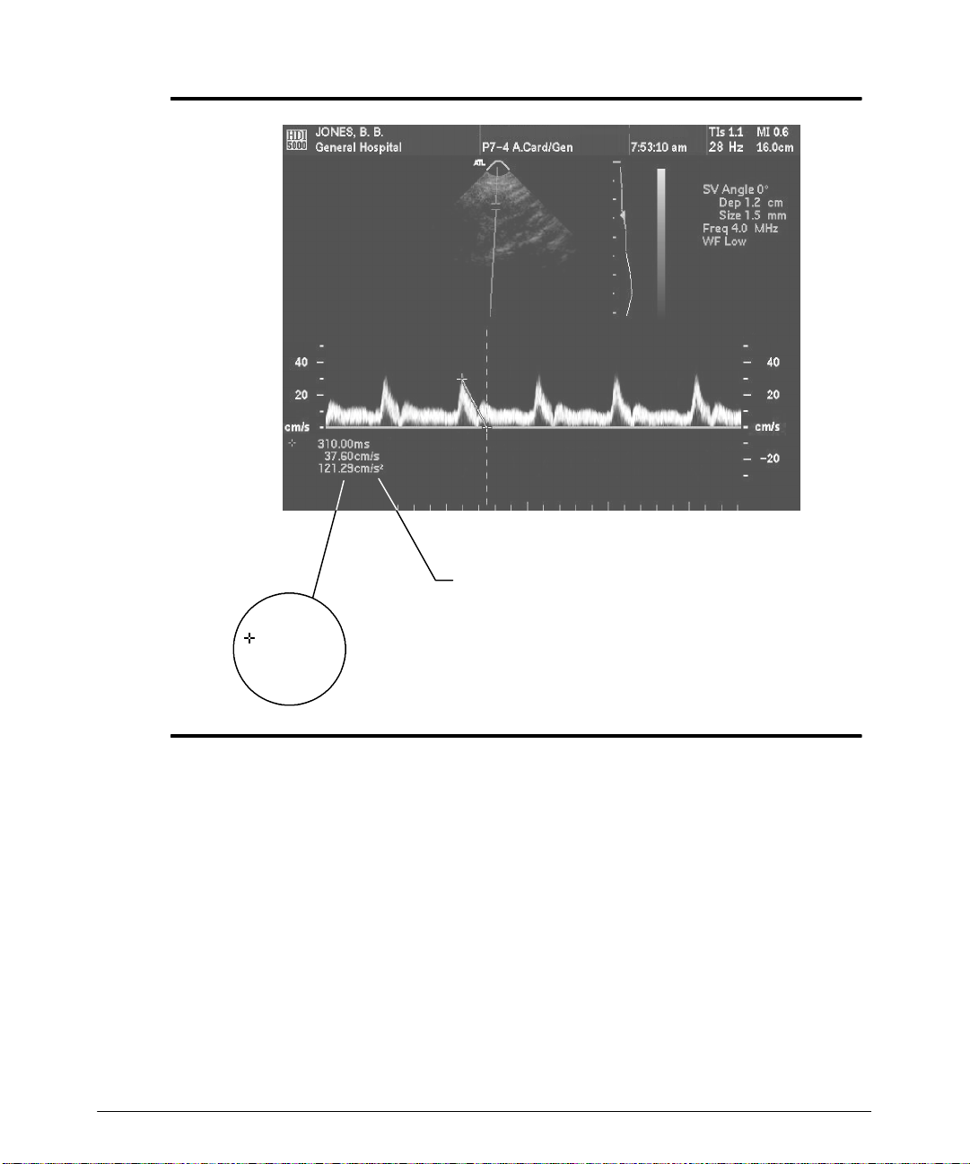
Making Measurements
Results (Doppler)
XX.XXms
XX.XXcm/s
XX.XXcm/s
Results for M-mode
Figure 6--16. Time/Slope Measurement Results
6-- 22
HDI 5000 Getting Started 4708-0027-03
Page 89

Making Measurements
Measuring Heart Rate
"""" T o measure the heart rate:
1. Acquire the desired scrolling display.
2. Press the FREEZE control.
3. Press the ADV MEAS control to display the Meas Tools menu.
4. Select Heart Rate. A vertical line cursor appears on the frozen scrolling display, extending through the scrolling display to the time line.
5. Use the trackball to position the cursor at a point in the heart cycle.
6. Press the SELECT control to fix the cursor position. Asecond cursor appears on the
display.
7. Usethe trackballto movethe cursor to an equivalent point in the next heart cycle.The
heart rate, in bpm, appears in the results and updates as cursors are moved or averaged int o t he r es ult s ( F igur e 6 -- 17) .
8. Continue to press SELECT and use the trackball to measure additional heart cycles.
The results, in bpm, are the average of the intervals that you measure.
9. At this point you can:
-- Press theCALCS control to store the measurement values into a patient report.
-- Press the FREEZE control to erase the measurement and resume imaging.
-- Press the DEL MEAS control to erase individual measurement cursors and
results until all are erased. The bpm results are adjusted accordingly .
HDI 5000 Getting Started 4708-0027-03
6-- 23
Page 90
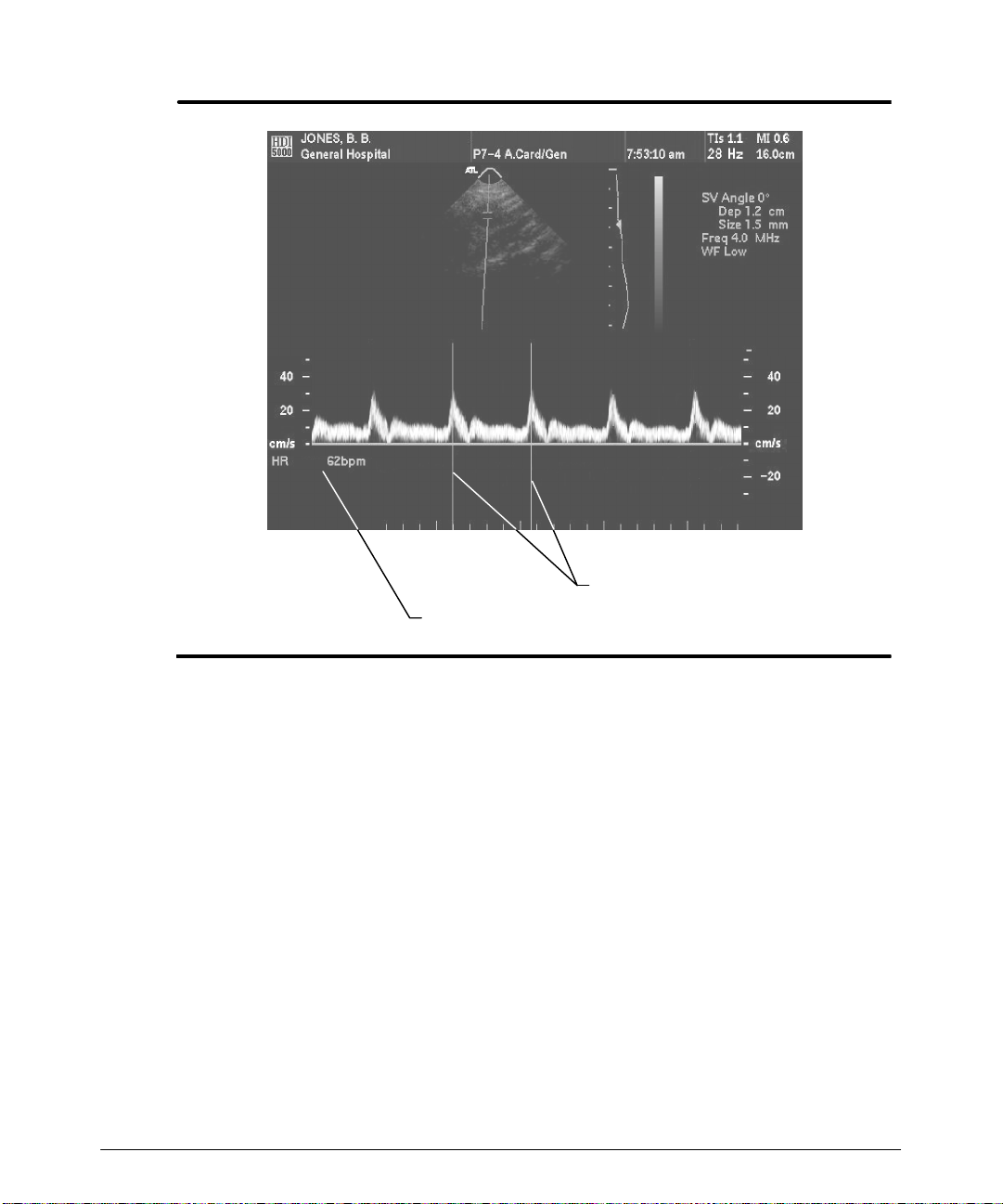
Making Measurements
Heart rate cursors
Heart rate measurement
Figure 6--17. Heart Rate Measurement (M-Mode Shown)
6-- 24
HDI 5000 Getting Started 4708-0027-03
Page 91
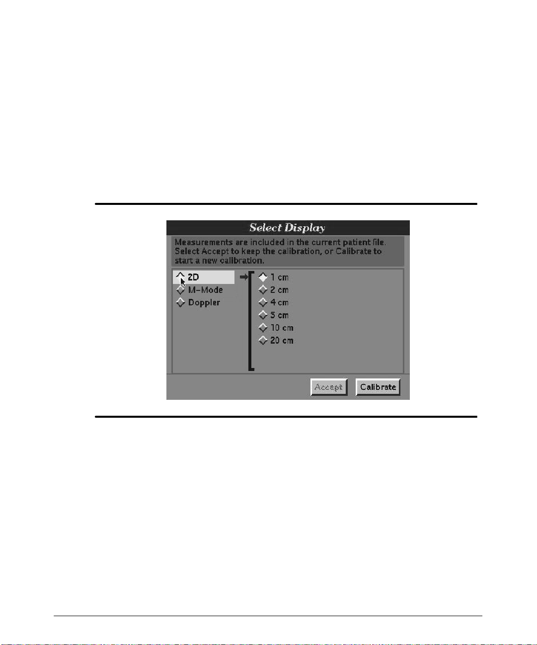
Making Measurements
Measuring Recorded or Stored Images
Anytime that you attempt to measure a recorded image (a VCR freeze-frame) or stored
image, the system requires certain information about the image. The process by which
youprovidethisinformationto thesystem is calledcalibration. The systemprovidesmessages and dialog boxes to guide you through the calibration procedure. Y ou can also
accept a previous calibration.
"""" T o select the Calibrate measurement tool:
1. Press the ADV MEAS control.
2. Select Calibrate to display the Select Display (Figure 6--18).
Figure 6--18. Select Display: 2D Calibration
"""" T o calibrate an image for measurement:
1. If you attempt to measure a recorded or stored image, the Select Display automati-
cally appears. Youcan accept thecurrent calibration, or you can choose to calibrate.
Proceed with step 2, if you select Calibrate ontheSelect Display.
2. Select 2D,M-Mode,orDoppler, depending upon thetype of image you want tomea-
sure. The parameters for the type of image appear:
-- Depth for a 2D frame (Figure 6--18)
-- Dept h and t im e f or an M - m ode f r am e ( F igur e 6 -- 19)
-- Type, orientation, time, and velocity or frequency for a Doppler frame
( F igur e 6 -- 20) .
HDI 5000 Getting Started 4708-0027-03
6-- 25
Page 92
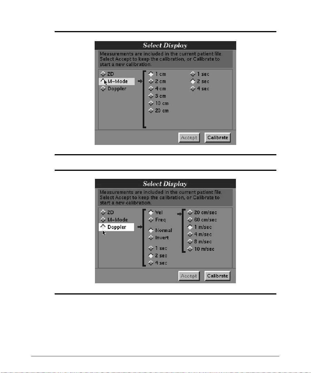
Making Measurements
Figure 6--19. M-Mode Calibration
6-- 26
Figure 6--20. Doppler Calibration
3. Select the calibration values that youwant for the type of frame you have selected in
s t ep 2. T he lar ges t c alibr at ion v alue t hat will f it in t he s c ale is t he bes t v alue t o us e f or
the calibration. For example: if you are displaying a depth of 15 cm in the image, then
the 10 cm calibration value will provide the most accurate calibration and,therefore,
the most accurate measurement.
HDI 5000 Getting Started 4708-0027-03
Page 93
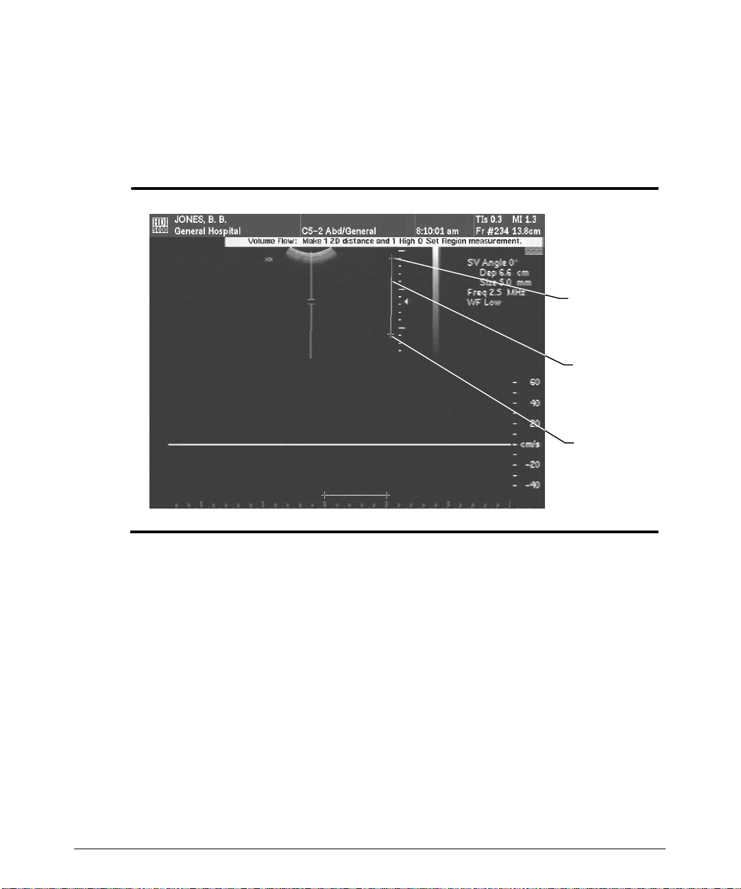
Making Measurements
4. Use the trackball to move the calibration cursors and use the SELECT control to set
them. Use the depth scale, the time scale, the frequency, or the velocity scales as
appropriate for a scale by which to position the calibration cursors. The separation
between the cursors along the scale that you use must correspond to the calibration
values select ed in st ep 3. T he syst em draws a line bet ween t he t wo cursor posit ions
(Figure 6--21). The image is calibrated and ready for measurment.
Calibration
cursor
Calibration
line
Calibration
cursor
Figure 6--21. Calibrate
"""" T o measure a calibrated image:
Measure the calibrated image, asrequired, using the measurement tools and procedures
described in this manual.
HDI 5000 Getting Started 4708-0027-03
6-- 27
Page 94

Making Measurements
High Q Automatic Doppler Measurement
HighQ automatic Doppler measurement refers to the automatic calculation anddisplay of
values for specified Doppler parameters. You specify which Doppler parameters will be
displayed. This is done in the Measurement setups. The results can be obtained from a
frozen display over aspecifiedregion of interest or the results can be obtained on a scrolling Doppler display on a real-time basis.
For accurate measurements, optimize the Doppler display as follows:
· The sample volume is centered in the vessel.
· Avoid measurements during simultaneous mode. Calculations derived from data
obtainedduring simultaneous mode willcompromisetheaccuracyofthe High Qautomatic calculations and the results.
· The spectral display does not exhibit aliasing.
· The angle correction cursor is parallel to the direction of flow.
"""" T o turn on the Mean Trace (for General Imaging clinical options):
1. Press the ADV MEAS control to display the Meas Tools menu.
2. Select Mean Trace(theDopplerdisplay mustbe scrollingto make thetrace selection)
to turn on the Mean Trace.
3. Highlight Trace on the Meas Tools menu. (The Doppler display must be scrolling to
make this selection.)
4. Press the SELECT control until thearea that you wish to includein the mean trace is
displayed. Theavailable selectionsare up, down, orall. (This selectionalso applies to
the peak trace.)
5. Obtain an optimal Doppler display.
The Doppler display mean tracing automatically occurs. (The mean trace is black; the
peak trace is blue.)
"""" To obtain High Q Doppler display results on a scrolling display:
1. Make the appropriate selections for the Doppler Results Display and the High Q
update interval in Measurements setups based on your application.
2. Obtain an optimal Doppler display.
â
â
3. P r es s t he HIGH Q
ââ
c ont r ol. T he Doppler dis play peak t r ac ing oc c ur s . ( T he peak
t r ac e is blue; t he m ean t r ac e is blac k . ) T he par am et er s t hat y ou s elec t ed in t he Do p -
pler Results Display will update in the results box based on the number of heart
cycles you select ed (F igure 6 -- 22).
6-- 28
HDI 5000 Getting Started 4708-0027-03
Page 95
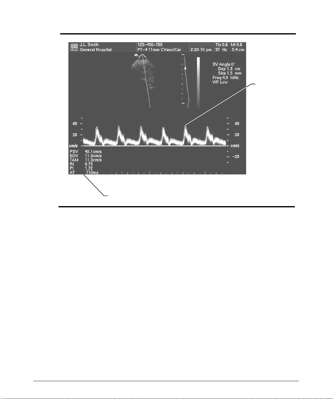
Making Measurements
Peak trace
Doppler results
Figure 6--22. High Q Automatic Doppler Results and Peak Trace
"""" To set a region for High Q automatic Doppler measurement:
Read the information about High Q measurement in the “Measurements” section of the
Ref er enc e M anual .
1. Make the appropriate selections for the Doppler Results Display and the High Q
update interval in Measurements Setups.
2. O bt ain an opt im al Doppler dis play.
3. Press the HIGH Q
ââââ
control. The Doppler display peak tracing automatically occurs
(the peak trace is blue), and the Doppler results automatically update based onyour
setups. (You can also perform this step after pressing the FREEZE control.)
4. Press the FREEZE control.
-- For general imaging clinicaloptions, press the ADV MEAS controland select Set
Region ( F igur e 6 -- 23) .
-- For cardiologyclinical options, two vertical line cursorsappear ontheDopplerdis-
play ( F igur e 6 -- 24) .
5. Position the first cursor at the onset of systole of the first heart cycle.
HDI 5000 Getting Started 4708-0027-03
6-- 29
Page 96
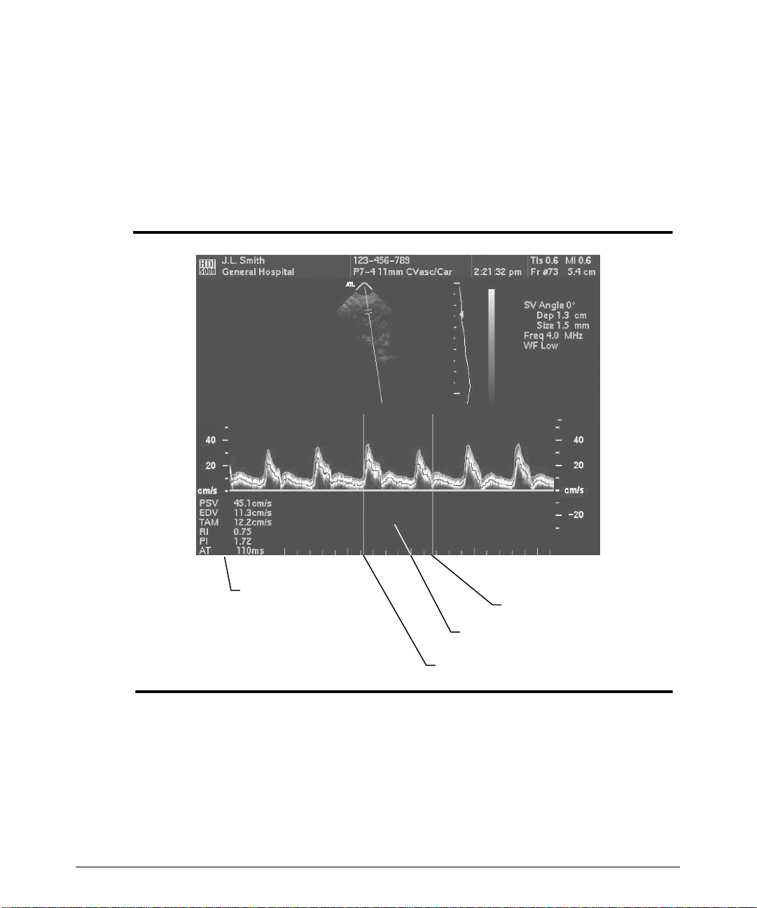
Making Measurements
6. Press the SELECT control.
7. Position the second cursor. Ensure that at least twosystolic peaks are included in the
region of interest.
8. Press the SELECT control to alternate between the cursors and adjust the cursor
positions.
The values for the parameters defined in the Measurements setups will be displayed for the region defined.
6-- 30
Results (dependent
upon Measurements
setups)
Cursor position
Region of interest
Cursor position
Figure 6--23. Set Region: General Imaging
HDI 5000 Getting Started 4708-0027-03
Page 97
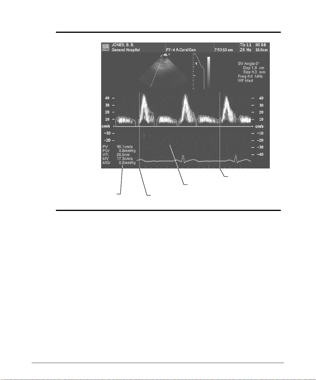
Making Measurements
Results (dependent
upon Measurements
setups)
Cursor position
Region of interest
Cursor position
Figure 6--24. Set Region: Cardiology
HDI 5000 Getting Started 4708-0027-03
6-- 31
Page 98

Making Measurements
Volume Flow
The volume flow measurement tool calculates volume flow for non-cardiology clinical
options, using a 2D distance measurement and a High Q time-averaged mean velocity
measurement. The volume flow calculation can be obtained from a frozen display or from
a real-time display.The Doppler scaling must be in velocity units. Diameter bar measurements are constrained to aline that is perpendicular to and passes through the center of
the angle correction cursor.
"""" T o measure volume flow:
2D Measurement
1. In2D-only imaging or Doppler imaging,acquirea2Dimagethat displaysalongitudinal
view of the vasculature under study.
2. Press the ADV MEAS control.
3. Select Vol Flow. The system automatically does the following:
-- Deletes existing measurement tools.
-- Turns on the High Q mean trace.
-- Turns off the High Q peak trace.
-- Displays the D-line and sample volume cursor and angle correction cursor in
2D-only imaging mode.
-- Sets the High Q control to control the mean trace.
6-- 32
4. Press the DISTANCE control. The first cursor of the diameter bar appears on the 2D
display.
5. On the 2D display, use the trackball to position the cursor on one side of the vessel
diameter.
6. Press the SELECT control to fix the position of the firstcursor and display thesecond
c ur s or of t he diam et er bar ( F igur e 6 -- 25) .
HDI 5000 Getting Started 4708-0027-03
Page 99
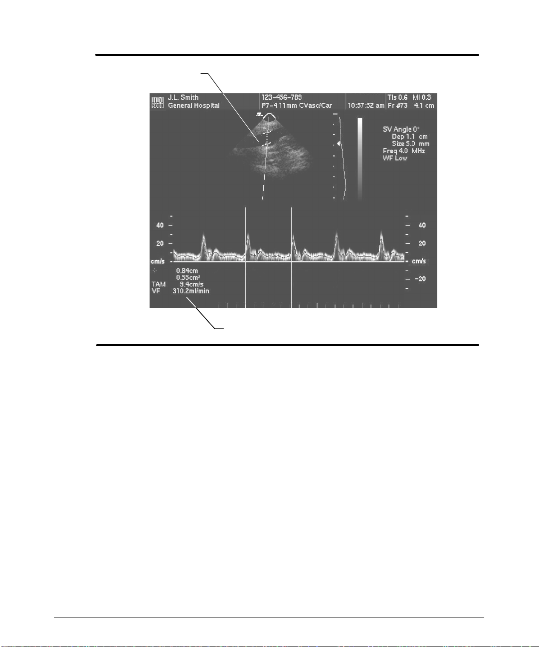
Making Measurements
Diameter bar
Results
Figure 6--25. V olume Flow: Diameter Bar Measure
7. Position the other cursor of the diameter bar on the other side of the vessel diameter.
The two cursors define the diameter of the vessel.
8. Press the SELECT control to end the 2D diameter measurement. The diameter bar
cannot be repositioned; a new2D diametermeasurementmust be started to make an
adjustment. (To start a new 2D measurement, press the DISTANCE control.)
Doppler Measurement
9. Position the samplevolumecursor within theareaofflowonthe2Dimageandobtaina
Dopplertrace. The volumeflow calculation based onthe real-time TAMvelocity is displayed in the results (Figure 6--25).
10. Todefine a specific region for volumeflow calculations, press the FREEZE control to
display two vertical cursors. To scroll back through the Doppler review memory:
a. Press the High Q control to turn off the mean trace.
b. Use the trackball to move through the Doppler review memory.
c. Pressthe High Q control todisplay themean trace and thevertical cursors again.
HDI 5000 Getting Started 4708-0027-03
6-- 33
Page 100

Making Measurements
1 1. Use the trackball and the SELECT control to define a region for volume flow calcula-
tion.
Cardiac Output (CO)
Thecardiacoutput measurementtool calculates cardiac output and stroke volume forcardiology clinical options, using a 2D distance measurement, a velocity time integral (VTI)
measurement, and a heart rate measurement from the same heart cycle as the VTI measurement. When the High Q Automatic Doppler featureis on, the peak velocity and heart
ratearedisplayedwhenthere is a frozenorreal-time display.Diametermeasurementsare
averaged.
"""" T o measure cardiac output:
2D Measurement
1. In 2D-only imaging or Doppler imaging, acquire a 2D image that displays the vasculature under study.
2. Press the ADV MEAS control.
3. Select CO. The system automatically does the following:
-- Deletes existing measurement tools.
-- Turns on the High Q peak trace.
6-- 34
4. Press the DISTANCE control. A first cursor of the diameter bar appears on the 2D
display.
5. On the 2D display, use the trackball to position the cursor on one side of the vessel
diameter.
6. Press the SELECT control to fix the position of the firstcursor and display thesecond
cursor of the diameter bar.
7. Position the other cursor of the diameter bar on the other side of the vessel diameter.
The two cursors define the diameter of the vessel.
8. Press the SELECT control to end the 2D diameter measurement. The diameter bar
cannot be repositioned; a new2D diametermeasurementmust be started to make an
adjustment.
Doppler Measurement
9. Position the samplevolumecursor within theareaofflowonthe2Dimageandobtaina
Doppler trace.
10. Press the FREEZEcontrol to display two vertical cursors. Toscroll back through the
Doppler review memory:
a. Press the High Q control to turn off the peak trace.
HDI 5000 Getting Started 4708-0027-03
 Loading...