

ATL AM2048 User Manual

User Guide
AM768A
AM2048A MP
AM2048A CAP
AM2048A OS/M
Ascom Telecom
1/187/500/610
Issue 8 - Dec 2001.
Part Number :

ascom telecom
USER GUIDE AM768A/AM2048A
THE INFORMATION CONTAINED IN
THIS DOCUMENT IS CONFIDENTIAL TO
ascom TELECOMMUNICATIONS LTD. AND MAY
NOT BE DISCLOSED OR REPRODUCED IN WHOLE
OR PART WITHOUT THEIR WRITTEN CONSENT.
©
ascom TELECOMMUNICATIONS LTD. 2001
2
Issue 8

ascom telecom
USER GUIDE AM768A/AM2048A
Note:
Ascom Telecommunications Limited reserves the right to make changes to this
Compliance Notes and Safety Instructions:
The information contained in this document is supplied without liability for errors or
omissions.
document at any time without notice.
Caution – Hazardous voltage inside the equipment
Safety Instructions:
This apparatus must be installed and maintained by SERVICE PERSONNEL.
Disconnect the mains plug and the NTP line connection before attempting to change
the user interface plug-in module.
The mains plug on the equipment serves as the disconnect device, therefore a socket
outlet shall be installed near the equipment and shall be easily accessible.
Power Rating Information – AC plug top adapter:
Voltage Range 240V – 10% +6%
Current Range 25mA to 50mA
Frequency Range 50/60Hz
Power Rating Information – 240V AC in-line adapter:
Voltage Range 240V – 10% +6%
Current Range 25mA to 50mA
Frequency Range 50/60Hz
Power Rating Information – 110V AC in-line adapter:
Voltage Range 110V – 10% +6%
Current Range 50mA to 100mA
Frequency Range 50/60Hz
Power Rating Information – DC Source:
Voltage Range 40.5V to 58V
Current Range 70mA to 200mA
TTE – Network Statement
Safety Statements
The copper DSL line connection has a safety status of TNV-3
The Plug Top DC Power connection has a safety status of TNV-2
The X.21 Digital Network Interface Port has a safety status of SELV
The V.35 Digital Network Interface Port has a safety status of SELV
The 10/100 BaseT Port has a safety status of SELV.
For the G.703 Port Connection to Unexposed Environments:
The Alarm Port has a safety status of SELV.
The G.703 Digital Network Interface Port has a safety status of SELV
For the G.703 Port Connection to Exposed Environments:
The Alarm Port has a safety status of earthed SELV.
The G.703 Digital Network Interface Port has a safety status of TNV-1
The Protective Earth on the rear panel MUST be connected (see Section 4 on
Installation)
3
Issue 8
ascom telecom
Definitions:
Exposed Environment
A TELECOMMUNICATIONS NETWORK is considered to be an exposed
environment if one or more conditions for an unexposed environment are not fulfilled.
Unexposed Environment
A TELECOMMUNICATIONS NETWORK is considered to be an unexposed
environment if the following conditions apply to all parts of the network
a) The possible effect of indirect lightning has been reduced by measures described
in IEC 61312-1.
b) The possibility of having different earth potentials has been reduced by
connecting all equipment within the network to the same equipotential bonding
system (see HD 384).
c) The possibility of power cross/contact has been reduced (see HD 384).
d) The possibility of induced transients and voltages has been reduced.
Caution – Laser Product
The Optical Interface is classified as a CLASS 1 LASER PRODUCT.
USER GUIDE AM768A/AM2048A
Caution – Electrostatic sensitive device
Electro-static discharge (ESD) Warning:
Antistatic precautions should be observed at all times.
If the unit is power fed from the DSL line interface then a functional earth MUST be
connected. (See Section 4 on Installation)
EMC Statement
This is a Class A product. In a domestic environment this product may cause
radio interference in which case the user may be required to take adequate
measures.
Manufacturers Declaration*
Ascom Telecommunications Limited declares that this product is in conformity with the
essential requirements of the ‘R&TTE directive 1999/5/EC’.
* A copy of the Declaration of Conformity is available upon request from Ascom Telecommunications Ltd.
4
Issue 8

ascom telecom
USER GUIDE AM768A/AM2048A
Contents
COMPLIANCE NOTES AND SAFETY INSTRUCTIONS:...................................3
1. INTRODUCTION........................................................................................................................................7
2. CONSTRUCTIONAL DETAILS................................................................................................................8
3. SYSTEM OVERVIEW..............................................................................................................................10
3.1 COPPER TRANSMISSION.........................................................................................................................10
3.2 OPTICAL TRANSMISSION .......................................................................................................................11
3.3 DSL TRANSMISSION FRAME .................................................................................................................12
3.4 CONTROL CIRCUIT.................................................................................................................................12
3.5 ALARM INTERFACE ...............................................................................................................................13
3.6 USER INTERFACE MODULES ..................................................................................................................13
4. INSTALLATION.........................................................................................................................................14
4.1 CONNECTION OF PROTECTIVE EARTH....................................................................................................14
4.2 POWER ON SEQUENCE...........................................................................................................................14
4.3 LOGGING ON .........................................................................................................................................14
4.4 SETTING MASTER/SLAVE MODE............................................................................................................ 15
4.5 SETTING THE USER INTERFACE .............................................................................................................15
4.6 SETTING THE NX64K USER DATA RATE ...............................................................................................16
4.7 SELECTING THE CIRCUIT CONFIGURATION............................................................................................16
4.7.1 Point to Point Link........................................................................................................................ 17
4.7.2 Point to Multipoint Link................................................................................................................20
4.8 BRINGING INTO SERVICE .......................................................................................................................22
4.9 TRANSMISSION PARAMETERS................................................................................................................23
4.9.1 Transmission Range......................................................................................................................23
4.9.2 End to End Delay..........................................................................................................................24
4.9.3 Jitter..............................................................................................................................................24
4.10 G.703 INTERFACE OPTIONS...................................................................................................................25
4.10.1 Unstructured Operation................................................................................................................25
4.10.2 Structured Operation....................................................................................................................26
4.10.3 Structured Working, CRCs Enabled.............................................................................................27
4.10.4 ETS 300 233 Loopbacks ...............................................................................................................28
5. PHYSICAL INTERFACES .......................................................................................................................30
5.1 MAINS POWER SUPPLY..........................................................................................................................30
5.1.1 240V Plug Top PSU......................................................................................................................30
5.1.2 240V In Line PSU.........................................................................................................................30
5.1.3 110V In-line PSU..........................................................................................................................30
5.2 DC POWER INLET ..................................................................................................................................30
5.3 COPPER TRANSMISSION LINE ................................................................................................................31
5.4 OPTICAL TRANSMISSION LINE...............................................................................................................31
5.5 SERIAL CONTROL ..................................................................................................................................31
5.6 ALARM INPUT/OUTPUT PORT ................................................................................................................32
5.7 INTERFACE MODULES ...........................................................................................................................33
5.7.1 G.703 ............................................................................................................................................33
5.7.2 X.21...............................................................................................................................................34
5.7.3 V.35...............................................................................................................................................35
5.8 FRONT PANEL........................................................................................................................................36
5.8.1 Controls........................................................................................................................................36
5.8.2 Indicators...................................................................................................................................... 37
5
Issue 8

ascom telecom
USER GUIDE AM768A/AM2048A
6. INTERNAL LINKS AND FUSES..................................................................................38
6.1 G.703 PLUG IN MODULE....................................................................................................................... 38
6.2 X.21 PLUG IN MODULE MK I................................................................................................................38
6.3 X.21 PLUG IN MODULE MK II..............................................................................................................39
6.4 V.35 PLUG IN MODULE (MK I AND MK II)...........................................................................................39
6.5 MOTHERBOARD.....................................................................................................................................40
7. COMPLIANCE NOTES ..............................................................................................................................41
7.1 TELECOMMUNICATION STANDARDS......................................................................................................41
8. GLOSSARY................................................................................................................................................42
9. TROUBLESHOOTING.............................................................................................................................44
APPENDIX A - X.21/V.35 CABLE LENGTHS...............................................................................................45
X.21 CABLES - POTENTIAL PROBLEM LENGTHS ...............................................................................................46
V.35 CABLES - POTENTIAL PROBLEM LENGTHS ...............................................................................................48
APPENDIX B – ORDERING INFORMATION .............................................................................................50
6
Issue 8

ascom telecom
USER GUIDE AM768A/AM2048A
1. Introduction
This manual applies to the High Speed DSL Systems, designed and manufactured by Ascom
Telecommunications Ltd in the U.K..
The modems provide synchronous communications at user data rates between 64kbps and 2048kbps
over up to three twisted pair cables or a single optical fibre. The equipment has modular transmission
and user interfaces, which allows the equipment to be configured to meet many different installation
requirements. Both rack and desktop versions of all units are available. Desktop units are AM2048A…
and rackmount units are AM2048B… This manual covers the desktop units.
The AM2048A OS provides full duplex transmission at 2.048Mbps over a single single-mode optical
fibre.
The AM2048A OM provides full duplex transmission at 2.048Mbps over a single multi-mode optical
fibre.
The AM2048A MP provides full duplex transmission at 2.048Mbps using 3 copper pairs. It can be
used in point to point or point to multipoint mode. The line code is 3B1O.
The AM2048A CAP provides full duplex transmission at 2.048Mbps using 1 or 2 copper pairs. It can
be used in point to point or point to multipoint mode. The line code is CAP.
The AM768A is a reduced cost unit, available with a single transmission module. This has most of the
functionality of the AM2048 but reduced payload bandwidth due to using one transmission line
instead of three. It is intended mainly for use in point to multipoint mode in conjunction with the
AM2048A MP or the AM2048B MP
Separate interface modules can also be purchased in order to modify the units for operation with a
different terminal interface at a later date.
Throughout the handbook, all types of unit are referred to as DSLU (Digital Subscriber Line Unit)
The DSLU can easily be configured via a dumb terminal. It is recommended to use a VT100 terminal
emulation program running on a notebook or palmtop PC. Using the menu system with on-line help
should reduce the need to refer to the handbook.
Once configured, the operation of the DSLU is totally automatic. In the event of line disturbances or
power failure, the data link is restored without operator intervention.
Chapter 4 (Installation) describes the basic set up procedure and this should be read prior to setting
up any link.
The VT100 Management User Guide gives a full description of the menu system..
Modifications to line cords and power supply leads are available for country specific requirements. In
such cases, the line cord pinout may be different. The basic model is the same, line cords and power
cords are separate plug in items.
7
Issue 8
ascom telecom
2. Constructional Details
USER GUIDE AM768A/AM2048A
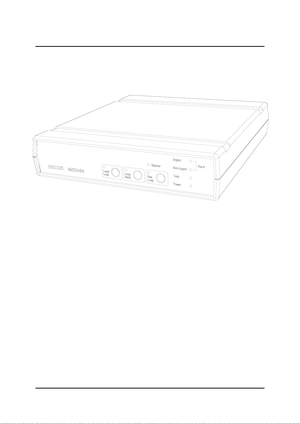
Figure 1 Desktop Unit
The desktop unit is housed in a grey non-flammable plastic case (UL94 rating V0). The membrane
front panel contains 5 LED indicators and 3 push button switches with LEDs to indicate their
activation.
LEDs
• Urgent Alarm
• Non Urgent Alarm
• Test
• Power
• Master
Buttons
• Local Loop
• Loop Back
• Rem Loop
8
Issue 8

ascom telecom
USER GUIDE AM768A/AM2048A
On the rear panel there are the following connectors:
–48V DC supply inlet socket 3-pin mini-fit
line interface 8 way RJ45 (Copper)
FC/SPC (Optical) See Appendix B for other options.
Management port interface 9 way female D-type
Alarm interface 13 way circular DIN
Data Ports (depending on module fitted)
G.703 120Ω 8 way RJ45
G.703 75Ω BNC
X.21 15 way D-type female
V35 34 way MRAC female
The data interface connector type will be from one of the three user specified interfaces available.
They are detailed in section 5. The plastic housing contains the main PCB. The plastic case has an
internal metallised layer for EMC screening purposes. The membrane front panel is attached to the
main PCB with a flexible circuit connector.
Also included is a 3 metre screened, stranded, Category 5 line cord terminated in 8-way RJ45 plugs
at both ends.
Optional plug-top and in-line mains adapters are available with a 1.8 metre long DC lead, terminating
in a 3-pin mini-fit plug. Also available is a VT100 Management connection cable.
The overall dimensions of the unit are 274mm(L) x 251mm(W) x 55mm(H).
9
Issue 8
ascom telecom
3. System Overview
USER GUIDE AM768A/AM2048A
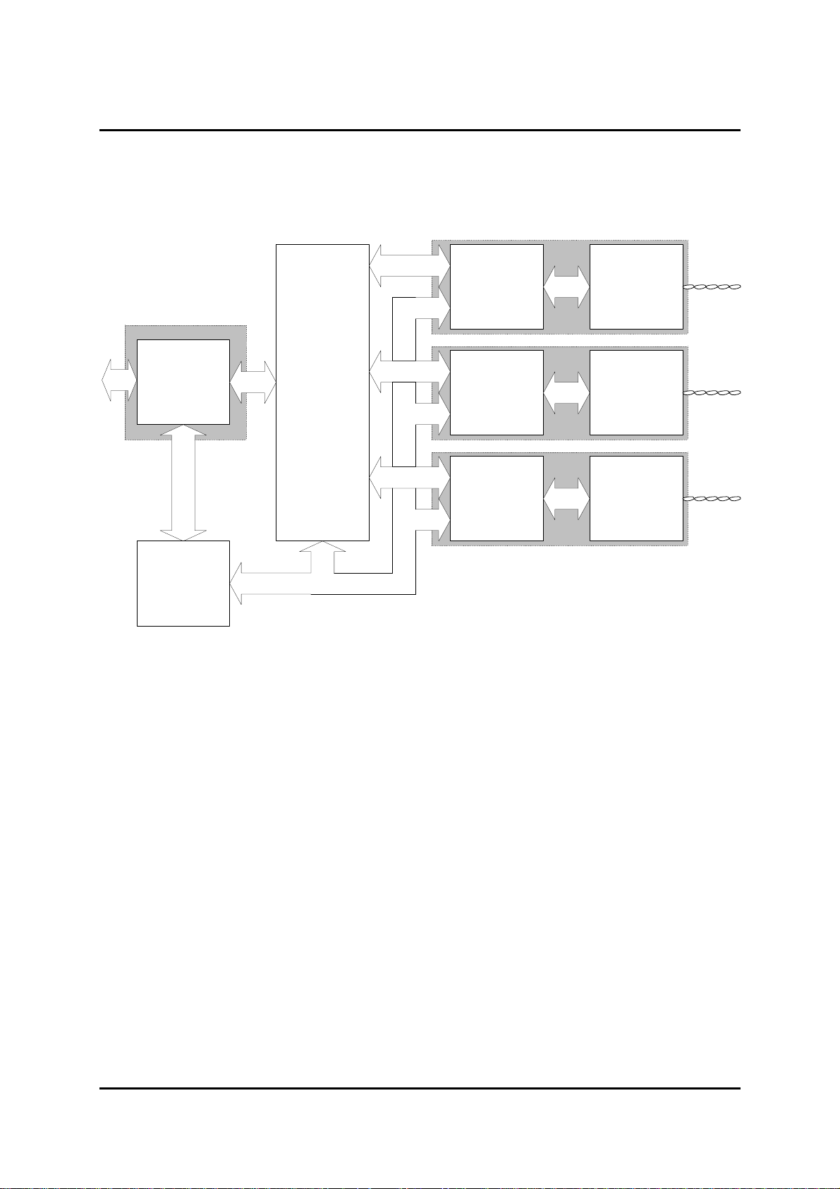
Transmission Modules
User Interface Module
G703
75/120
ohms
Primary Rate
Interface
Micro
Controller
ascom
HDSL
Interface
Chip
Figure 2 Copper System Block Diagram
DSP
Chip
DSP
Chip
DSP
Chip
Transceiver
Analogue
Interface
Transceiver
Analogue
Interface
Transceiver
Analogue
Interface
Pair 1
Pair 2
Pair 3
3.1 Copper Transmission
The copper system is intended for operation on 2-wire local telephone network circuits, such as those
meeting BT EPS-9 (Note: the DSLU requires between one and three such circuits). It will operate
satisfactorily on unloaded lines having a wide range of characteristics; bridge taps can be tolerated,
dependent upon their characteristics. Although, the system requires a baseband circuit, a continuous
loop at DC is not required. The system can transmit data at rates between 64k and 2048k.
For the copper system, echo cancellation is used to eliminate the unwanted reflections of the
transmitted signal from the receiver input.
The line is connected to the transmission circuit via a line transformer, which acts as a balun and
provides isolation; there is surge protection across the transformer line connections. The transmission
circuit utilises a custom IC and a number of proprietary components to perform the signal processing
described above.
When more than one transmission line is in operation, each transmission system operates with the
same bit rate derived from an oscillator in the master unit.
10
Issue 8
ascom telecom
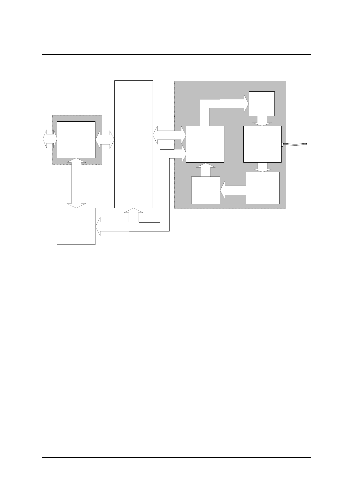
User Interface Module
USER GUIDE AM768A/AM2048A
Optical Transmission Module
Laser
Driver
G703
75/120
ohms
Primary Rate
Interface
Micro
Controller
ascom
HDSL
Interface
Chip
ascom
Tranceiver
Codec
Chip
Clock
Recovery
Optical
Duplexer
Analogue Rx
and
Channel
Separation
Filter
Figure 3 Optical System Block Diagram
3.2 Optical Transmission
The optical transmission interface module fits into the same envelope as three copper modules and is
designed to operate over a single optical fibre. This is accomplished using an optical duplexer, which
integrates a laser and a photodiode in a single package. Both directions are transmitted at the
1310nm optical window, leaving the 1550nm window free. The interface module encodes the DSL
framed data using a 5B6B block code for error monitoring and spectral shaping.
Sub-carrier modulation is used to increase the separation between the upstream and downstream
directions. Baseband transmission is used from ELU to NTU, whereas the other direction is
modulated onto a carrier.
For transmission over single-mode fibre, order the AM2048 OS.
For transmission over multi-mode fibre, order the AM2048 OM.
The AM2048A OS and AM2048 OM are Class I products in accordance with EN60825-1 and
therefore inherently safe.
11
Issue 8

ascom telecom
USER GUIDE AM768A/AM2048A
3.3 DSL Transmission Frame
Both of the above transmission systems operate in a bit pump mode. The DSL frame is sent over this
‘data pipe’. The DSL frame contains the following
• Sync word
• Stuff bits
• Stuff control bits
• EOC channel
• Customer data
The nominal DSL frame is always 6ms long, regardless of the transmission rate of the individual
channels.
The DSL frame length is adjusted slightly by the use of stuff bits. There may be 4 stuff bits or 2 stuff
bits per frame. The stuff bits are used to adjust the effective payload bandwidth of the DSL frame.
If the user rate clock is slightly quicker than the line rate clock then less stuff bits are sent.
Alternatively, if the user rate clock is slightly slower than the line rate clock then more stuff bits are
sent. This mechanism allows the line rate bandwidth to be adjusted to match the user rate bandwidth.
At the receive end, the rate at which the stuff bits arrive is used to recover the user clock.
The transmit and receive paths may be operated independently from one another so that when a
G.703 user interface is present, the transmit and receive clocks are allowed to vary independently by
50ppm. (Note. When operating with X.21 or V.35 interfaces, there is only a single clock at each user
+
interface.)
The Embedded Operation Channel (EOC) is carried in spare overhead bits in the transmission frame.
Packetised SNMP SET and GET messages are passed over the link from the ELU to the NTU, which
answers with the appropriate SNMP response.
Byte timing is maintained by the transmission system and is available if required.
3.4 Control Circuit
The control circuit is based on a micro-controller and determines the operational status of the unit
according to the state of the transmission system, the data interface and the configuration information
received from the terminal.
Configuration data and two copies of the application are stored internally in FLASH memory. On
power-up the application program is copied from FLASH to RAM from where it is executed. The main
application program is backed up so that if a corruption occurs it can be corrected. This also enables
the programming of a new application while the equipment is operating normally. Control is
transferred to the new application after an automatic restart at the end of the download. This
minimises the interruption of payload traffic. Also, if programming is interrupted, the previous version
of software will remain intact. A new application program may also be downloaded from the ELU to
the remote NTU over the line.
12
Issue 8

ascom telecom
USER GUIDE AM768A/AM2048A
3.5 Alarm Interface
A 13 pin circular DIN connector provides access to 6 alarm inputs that are used to detect metallic
contact closure. For example, they can be used to sense a cabinet door open or temperature sensors.
The priority of these auxiliary alarms may be programmed through the “Alarms>Severity Level
Settings” screen.
There are also relay contact outputs to indicate urgent and non-urgent alarms. This allows the system
to be easily integrated into the alarm systems of other equipment.
3.6 User Interface Modules
The user interface is provided by a plug-in module of which there are six types:
• G.703, with software selectable 75ohm or 120ohm ports
• X.21
• V.35
• G.703 MK II (with 1 + 1 protection switch)
• X.21 MK II (with tail buffer)
• V.35 MK II (with tail buffer)
The existing interface module can be changed out using a pluggable replacement unit. These can be
ordered separately using the part numbers detailed below. For part numbers and order codes see
Appendix B.
13
Issue 8
ascom telecom
USER GUIDE AM768A/AM2048A
4. Installation
This chapter describes the basic steps that are required to set up a system involving the DSL Modem.
4.1 Connection of Protective Earth
If it is required to connect the G.703 port to a circuit that is defined as TNV, then a protective earth
must be connected to the earth bond stud on the rear panel. See the Compliance Notes and Safety
Instructions inside the front cover.
If the unit is power fed then a functional earth must be connected to the earth bond stud on the rear
panel to provide a discharge path to ground for ESD protection. See the Compliance Notes and
Safety Instructions inside the front cover.
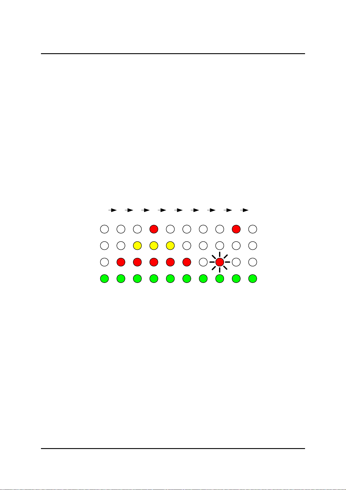
4.2 Power On Sequence
With no DTE or line connected to the DSLU on power up, the following LED sequence will be
displayed:
2345678 9 10
1
Urgent
Non-Urgent
Test
Power
Prior to the sequence starting, a random pattern may appear momentarily.
During sequence 1 to 7 the LEDs are illuminated in turn as an LED confidence test.
During stage 8 the test LED flashes as the internal self-test sequence is completed. The flashing will
normally last for about 4 seconds, however, if a new application has been loaded this time will be
extended by about 10 seconds while a backup copy of the application is made.
With no external connections the unit will sense the loss of external signals, raise the urgent alarm
and stop at stage 9.
When the system has been installed and is working correctly, the unit should move to stage 10.
4.3 Logging On
Connect a VT100 terminal (or PC running a VT100 emulation program) to the 9-way serial port on the
rear of the unit. The log on screen should appear automatically once the DSLU detects the terminal.
Type ‘C’ to select Configuration, then press ‘Enter’
Type ‘ascom’ the default password setting, then press ‘Enter’
The top level menu system displays the sub-menus available.
For a full description of the menu system, refer to the ‘VT100 Management User Guide’.
14
Issue 8

ascom telecom
USER GUIDE AM768A/AM2048A
4.4 Setting Master/Slave mode.
For all modes of operation, one unit must be set to master mode, while the other unit is set to slave
mode. The master unit is referred to as the ELU or Exchange Line Unit and the slave unit is referred
to as the NTU or Network Terminating Unit. The front panel ‘Master’ LED indicates the mode of the
unit.
The ELU is a ‘master’ in several senses. The master end provides the source of the bit rate timing for
the transmission line(s). The ELU is also the ‘master’ from a network management point of view. It
contains the database of configuration information for itself and all connected NTUs. The alarm and
performance monitoring history is saved at the ELU. When the management terminal is connected to
the ELU it can read all of the information from the remote NTU, whereas when the management
terminal is connected to the NTU, only the local information is obtainable.
The factory default is for the unit to be configured as a slave (NTU).
To change the setting, using the terminal go to the “Configuration>Master/Slave” screen and select
the appropriate option. (use the arrow keys or tab key to navigate and the spacebar to change the
setting). The basic setup for all modes is as follows:
At the master end:
Configuration>Master/Slave
1. select Master.
2. select Point- to Point or Point to Multipoint, as appropriate.
3. enable the required number of lines
At the slave end:
The factory default setting should allow the units to get into sync, otherwise:
Configuration>Master/Slave
4. select Slave.
5. select Point- to Point or Point to Multipoint, as appropriate.
6. enable the required number of lines
The unit will automatically reboot with the new settings once the “return” key is pressed to accept the
changes. You will then be invited to log back on to the system.
It is possible to set Master/Slave by using the front panel buttons if a terminal is unavailable, see
section 5.8.1.
4.5 Setting the User Interface
The unit automatically detects what kind of user interface is plugged in and displays the appropriate
screen in the “Configuration>User Port” screen.
For X.21 and V.35, DTE/DCE selection is carried out by moving the link header on the user interface
plug-in module. The software automatically senses the link setting and sets the unit up accordingly.
To check the user interface and any link settings, using the terminal, go to the “Information>System”
screen, this will display which user interface has been plugged in, and which mode it is in.
Once a unit is configured as an ELU, the expected interface at the NTU may be set, or by default, the
unit will auto-discover the NTU user port configuration after the line gets into synchronisation.
15
Issue 8

ascom telecom
USER GUIDE AM768A/AM2048A
4.6 Setting the Nx64K User Data Rate
For X.21 and V.35 the data rate may be set in increments of 64kbps. The default setting of N = 6. The
data rate is set by entering the desired value of N. The full range of N is from 1 to 32. The screen
display gives the equivalent data rate in kbps for the value of N. The software automatically restricts
the value of N to match the user interface and line interface combination. e.g. for an Am768, the
maximum value of N = 12.
For a G.703 to Nx64 configuration, the maximum value of N is 31 as only timeslots 1 to 31 are
transported over the transmission link. N may be further restricted depending on the transmission
system.
For software up to version 2.9
At the master end:
Configuration>User Port
1. Set the desired value of N.
2. Press F8, to select the remote end
3. Set the desired value of N
4. Press Enter to activate the change.
For software versions greater than 2.9
At the master end:
Configuration>User Port
1. Set the desired value of N.
2. Press Enter to activate the change.
, the value of N must be entered for each end of the link as follows:
, the value of N only needs to be set once:
4.7 Selecting the Circuit Configuration
The term ‘digital section’ refers to the data link between the user ports of the connected DSLUs.
In a standalone section, the DSLUs provide the complete transmission system.
In a tandem section, the DSLUs are used to extend an existing circuit or network port. To achieve
synchronous data transfer, the master DSLU must derive its timing from the circuit to which it is
connected.
A Point to Point link requires two DSLUs, one master and one slave.
A Point to Multipoint link can have up to four DSLUs, one master and up to three slaves.
The DSLU at one end of the digital section is selected to be a Master (ELU), the remote end(s) are
selected to be slave(s) (NTUs).
For a tandem section, the DSLU connected to the tandem section is configured as the master.
Please refer to the diagrams on the following pages.
16
Issue 8
 Loading...