

ATL AM200 User Manual

AM200 USER GUIDE

ATL User Guide
AM200 Modem
2
ATL Part No 1/360/001/610
Issue 04 JUne 2004
Disclaimer
The information contained in this document is confidential to ATL Telecom Ltd. and may not be disclosed or
reproduced in whole or in part without their written consent.
© ATL Telecom Ltd 2004.
Note: The information contained in this document is supplied without liability for errors or omissions.
ATL Telecom Limited reserves the right to make changes to this document at any time without notice.

ATL User Guide
AM200 Modem
3
COMPLIANCE NOTES & SAFETY INSTRUCTIONS
Caution: - Hazardous voltages inside the equipment
Safety Instructions:
This apparatus must be installed and maintained by SERVICE PERSONNEL.
There are NO user serviceable parts inside the modems.
Caution: - Electrostatic sensitive devices inside the equipment
Electrostatic discharge (ESD) Warning:
Antistatic precautions should be observed at all times.
Power Rating Information - AC Version:
Voltage Rating 85Vrms to 250Vrms
Maximum Current 100mA
Frequency Range 50 - 60Hz
Power Rating Information - DC Version:
Voltage Rating -18V to -72V
Maximum Current 222mA
Disconnect Device Statement:
For the AM200 DC Version the DC input socket serves as the disconnect device.
TTE - Network Safety Statement:
The AM200 is a Class 1 product and must be connected to a reliable earth connection. If the MAINS EARTH
cannot be guaranteed to be PROTECTIVE EARTH, then a PROTECTIVE EARTH conductor must be connected
to the M3 stud on the REAR PANEL of the unit.
Safety Classification of traffic Ports
The DSL line connection has a safety status of TNV-3
10/100BaseT - 8 WAY RJ45 connection has a safety status of UNEARTHED SELV.
X21/V35 - 25 WAY FEMALE D-Type connection has a safety status of EARTHED SELV.

ATL User Guide
AM200 Modem
4
G703 connected to an Unexposed Environment:
Tx 75ohm BNC connection has a safety status of EARTHED SELV.
Rx 75ohm BNC connection has a safety status of UNEARTHED SELV.
120ohm 8WAY RJ45 connection has a safety status of UNEARTHED SELV
For the DC version, the M3 stud on the rear panel MUST be connected to ground.
G703 connected to an Exposed Environment:
Tx 75ohm BNC connection has a safety status of EARTHED TNV-1.
Rx 75ohm BNC connection has a safety status of UNEARTHED TNV-1.
120ohm 8 WAY RJ45 connection has a safety status of UNEARTHED TNV-1.
For the DC version, the M3 stud on the rear panel MUST be connected to ground.
Safety Status Classification of non-traffic PORTS
Mains Input - IEC320 85Vrms - 250Vrms 50/60Hz connection has a safety status of PRIMARY CIRCUIT.
DC Input - TNV-2
Management Port Interface - 9 WAY FEMALE D-Type connection has a safety status of EARTHED SELV.
Definitions
Exposed Environment
A TELECOMMUNICATIONS NETWORK is considered to be an exposed environment if one or more conditions
for an unexposed environment are not fulfilled.
Unexposed Environment
A TELECOMMUNICATIONS NETWORK is considered to be an unexposed environment if the following
conditions apply to all parts of the network
a) The possible effect of indirect lightening has been reduced by measures described in IEC 61312-1.
b) The possibility of having different earth potentials has been reduced by connecting all equipment
within the network to the same equipotential bonding system.
c) The possibility of power cross/contact has been reduced.
d) The possibility of induced transients and voltages has been reduced.
Manufacturers Declaration*
ATL Telecom Limited declares that this product is in conformity
with the essential requirements of the 'R&TTE directive 1999/5/EC'.
*A copy of the Declaration of Conformity is available upon request from ATL Telecom Ltd.

ATL User Guide
AM200 Modem
5
1 SCOPE 11
2 INTRODUCTION 12
3 EXAMPLE APPLICATIONS 14
3.1 AM200 BACK TO BACK SET-UP (INTEGRATED VOICE & DATA TRANSMISSION) 14
3.2 AM200 TO AM200 CONNECTION VIA AN AM7000 MULTIPLEXER (CROSS CONNECTION) 14
3.3 AM200 MODEMS CONNECTED TO A D.D.N. VIA AN AM7000 MULTIPLEXER AT 1.024Mbps 15
4 CONSTRUCTION 16
4.1 AM200ALE FRONT PANEL 16
4.2 AM200AE FRONT PANEL 16
4.3 AM200 REAR PANEL 17
4.3.1 AC VARIANT 3-PIN IEC MAINS INLET SOCKET AND SWITCH 17
4.3.2 DC VARIANT 17
4.3.3 REAR CONNECTORS COMMON TO AC & DC VARIANTS 18
5 INSTALLATION 19
5.1 CONNECTION OF PROTECTIVE EARTH 19
5.2 LED POWER ON SEQUENCE 19
5.3 LCD POWER ON SEQUENCE 19
5.4 DEFAULT SETTINGS 19
6 QUICK START GUIDE 21
6.1 SET ONE END TO CO 21
6.2 LINE RATE 21
6.3 ETHERNET 22
6.3.1 CONFIGURATION AS A BRIDGE 22
6.3.2 CHANGING AN AM200 FROM ROUTER TO BRIDGE 23
6.3.3 C0NFIGURATION AS A ROUTER 24
6.4 G703 26
6.5 Nx64 27
7 SELECTING THE CIRCUIT CONFIGURATION 28
7.1 STANDALONE SECTION 28
7.1.1 INTERNAL TIMING 29
7.1.1.1 G.703 to G.703 Internal Timing Master 29
7.1.1.2 G.703 to X.21/V.35 Internal Timing 29
7.1.1.3 X.21/V.35 DCE to X.21/V.35 DCE 30
7.1.2 G.703 TO G.703 TRANSPARENT TIMING 30
7.2 TANDEM SECTION - EXTERNAL TIMING 31
7.2.1 G.703 TO G.703 EXTERNAL TIMING 31
7.2.2 X.21/V.35 DTE-TO X.21/V.35 DCE 32
7.2.3 G.703-TO X.21/V.35 DCE 32
7.3 CROSSING AN SDH NETWORK 33

ATL User Guide
AM200 Modem
6
7.4 CROSSING A PDH NETWORK 33
8 SETTING UP USING CLI 34
8.1 CONNECTION VIA TERMINAL PORT 34
8.2 CONNECTION VIA ETHERNET PORT - TELNET 35
8.3 CLI COMMAND STRUCTURE 36
8.3.1 <GROUP> 36
8.3.2 <SUB-GROUP> 36
8.3.3 <COMMAND> 36
8.3.4 <INSTANCE> 36
8.3.5 <ATTRIBUTE-NAME> 36
8.3.6 <ATTRIBUTE-VALUE> 37
8.4 CLI HELP COMMAND 38
8.5 CLI AUTO COMPLETE 40
8.6 CHANGING THE IP ADDRESS 41
8.7 SETTING CO/CPE 41
8.7.1 TO SET THE AM200 AS CPE 41
8.7.2 TO SET AS CO 41
8.8 SETTING THE DSL LINE RATE 41
8.9 MANAGEMENT MODE 43
8.10 THE USER INTERFACE 44
8.10.1 ETHERNET PORT 44
8.10.1.1 Setting the Ethernet User Port Data Rate 44
8.10.1.2 Enabling Alarm Reporting 44
8.10.2 G703 USER PORT 44
8.10.2.1 Enabling the G703 Alarm Reporting 44
8.10.2.2 Setting the G703 Time slots 44
8.10.3 NX64 USER PORT 45
8.10.3.1 Enabling the Nx64 Alarm Reporing 45
8.10.3.2 Setting the Nx64 User Port Type 45
8.10.3.3 Setting The Nx64k User Port Data Rate 46
8.11 BRIDGE 48
8.12 ROUTER 50
8.13 RIP 51
8.14 RESTORING FACTORY DEFAULT 52
8.15 SAVING CLI CHANGES 52
8.16 RESTORING TO SAVED SETTINGS 52
8.17 EXAMPLE CONFIGURATION 53
8.17.1 G703 EXAMPLE CONFIGURATION 53
8.17.2 V35 EXAMPLE CONFIGURATION 54
8.17.3 V35 & G703 EXAMPLE CONFIGURATION 55

ATL User Guide
AM200 Modem
7
9 SETTING UP USING WEB BROWSER 57
9.1 INTERNET/EXPLORER SET-UP 57
9.2 OPENING THE WEB BROWSER 58
9.3 WEB BROWSER MENU'S 58
9.3.1 HELP 59
9.3.2 STATUS 60
9.3.3 SYSTEM 61
9.3.3.1 Error Log 61
9.3.3.2 Hardware 61
9.3.3.3 Inventory 62
9.3.3.4 Remote Access 63
9.3.3.5 Upgrade 63
9.3.3.6 Restart 64
9.3.3.7 System Time 65
9.3.4 ADVANCED STATUS 66
9.3.4.1 DHCP Server 66
9.3.4.2 DNS Client 66
9.3.4.3 DNS Relay 67
9.3.4.4 Security 67
9.3.4.5 User Ports 68
9.3.4.5.2 HDLC 69
9.3.4.5.3 Nx64 69
9.3.5 PERFORMANCE 70
9.3.5.1 DSL 70
9.3.5.2 DS1 71
9.3.6 CONFIGURATION 71
9.3.6.1 Save 72
9.3.6.2 Authentication 72
9.3.6.3 DHCP Server 73
9.3.6.4 DNS Client 75
9.3.6.5 DNS Relay 76
9.3.6.6 DEVICE 77
9.3.6.7 IP Routes 79
9.3.6.8 Login 80
9.3.6.9 Security 80
9.3.6.10 User Ports 82
9.3.6.10.1 DS0 82
9.3.6.10.2 DS1 User Port 83
9.3.6.10.3 HDLC Port 85
9.3.6.10.4 N*64 User Port 87

ATL User Guide
AM200 Modem
8
9.3.7 TEST 90
9.3.7.1 DS0 90
9.3.7.2 DS1 90
9.3.7.3 Nx64 91
9.3.7.4 BERT TESTER 92
10 SETTING UP USING THE LCD 93
10.1 MENU STRUCTURE 93
10.1.1 SHOW SUB-MENUS 93
10.1.2 SET SUB-MENUS 93
10.1.3 MENU STRUCTURE LAYOUT 94
10.2 AM200 MENU 95
10.2.1 SHOW OPTION 95
10.2.2 SET OPTION 96
10.2.2.1 DS1MODE 97
10.2.2.2 MANAGEMENT MODE 97
10.2.2.3 EXPECTED MODEL 97
10.2.2.4 LINE RATE 98
10.2.2.5 ENABLE LINE 98
10.2.2.6 LCD TIME 98
10.3 INVENTORY MENU 99
10.3.1 SHOW OPTION 99
10.4 DS0 MENU 100
10.4.1 DS0 SHOW OPTION 100
10.4.2 DS0 SET OPTION 100
10.4.2.1 ENABLE TIMESLOTS 101
10.4.2.2 SET LOOPBACKS 101
10.5 DS1 MENU 102
10.5.1 DS1 SHOW OPTION 102
10.5.2 DS1 SET OPTION 103
10.5.2.1 ADMIN STAUS 104
10.5.2.2 LINE TYPE 104
10.5.2.3 TxC CLOCK SOURCE 104
10.5.2.4 CHANNELIZATION 105
10.5.2.5 TIMESLOTS 105
10.5.2.6 LOOPBACK 105
10.5.2.7 LINK TRAP ENABLE 106
10.5.2.8 STATUS TRAP ENABLE 106
10.6 HDLC MENU 106
10.6.1 HDLC SHOW OPTION 106
10.6.2 HDLC SET OPTION 107

ATL User Guide
AM200 Modem
9
10.6.2.1 ADMIN STAUS 107
10.6.2.2 NTimes64K 108
10.6.2.3 Link Trap Enable 108
10.7 Nx64 MENU 108
10.7.1 NX64 SHOW OPTION 109
10.7.2 NX64 SET OPTION 11 0
10.7.2.1 ADMIN STAUS 110
10.7.2.2 NTimes64K 111
10.7.2.3 TYPE 111
10.7.2.4 MODE 111
10.7.2.5 ENABLE DTE CLOCK 112
10.7.2.6 106 CLAMP 112
10.7.2.7 LOCAL LOOP 112
10.7.2.8 LOOP BACK 11 2
10.7.2.9 LINE TRAP 113
10.7.2.10 SIGNAL LOSS 113
10.7.2.11 CLOCK OUT OF RANGE 113
10.8 SYSTEM MENU 114
10.8.1 RESTART 11 4
10.8.2 CONFIGURE 114
10.8.2.1 SAVE 114
10.8.2,2 RESTORE 115
11 COMMISSIONING 116
11.1 PERFORMANCE VIA WEB BROWSER 116
11.1.1 DSL 116
11.1.2 DS1 117
12 OPERATION & MAINTENANCE 118
12.1 INTERNAL LINKS & FUSES 118
12.1.1 AC VARIANTS 118
12.1.2 DC VARIANTS 118
12.1.3 G703 USER PORT 118
13 SPECIFICATION 119
13.1 AM200 DIMENSIONS 11 9
13.2 TRANSMISSION PERFORMANCE 119
13.2.1 END TO END DELAY 119
13.2.2 JITTER 119
13.2.3 TRANSMISSION RANGE 119
13.3 AC POWER INLET 120
13.4 DC POWER INLET 120
13.5 DC POWER CABLE 121

ATL User Guide
AM200 Modem
10
13.6 COPPER TRANSMISSION LINE 121
13.7 TERMINAL CONNECTION 122
13.8 INTERFACE CONNECTION 123
13.8.1 ETHERNET PORT 123
13.8.2 G703 124
13.8.2.1 G703 75 Ohm 124
13.8.2.2 G703 120 Ohm 124
13.8.3 RS530 DCE 125
13.8.4 RS530 DTE 126
13.8.5 V35 DCE 127
13.8.6 V35 DTE 128
13.8.7 X21 DCE 129
13.8.8 X21 DTE 130
13.9 MOUNTING BRACKET 131
13.10 ENVIRONMENTAL 132
13.10.1 TRANSPORTATION 132
13.10.2 STORAGE 132
13.10.3 OPERATIONAL 132
14 SYSTEM OVERVIEW 133
14.1 COPPER TRANSMISSION 133
14.2 DSL TRANSMISSION FRAME 133
14.3 CONTROL CIRCUIT 134
15 COMPLIANCE NOTES 135
15.1 TELECOMMUNICATION STANDARDS 135
16 ORDERING INFORMATION 136
16.1 USER INTERFACES 136
16.2 AM200 DESKTOP UNITS, NON LCD 136
16.3 AM200 DESKTOP UNITS, WITH LCD 136
16.4 SPECIAL AM200 VARIANTS 136
16.5 ACCESSORIES 136
17 F.A.Q.s 137
18 Appendix 1 Glossary 138

ATL User Guide
AM200 Modem
11
1
1 SCOPE
This User Guide applies to the AM200 DSL modem designed and manufactured by ATL Telecom Limited in
the U.K. It provides guidance for installation, commissioning and operation of the modem as well as reference
information covering maintenance, specification and compliance.
ATL User Guide
AM200 Modem
12
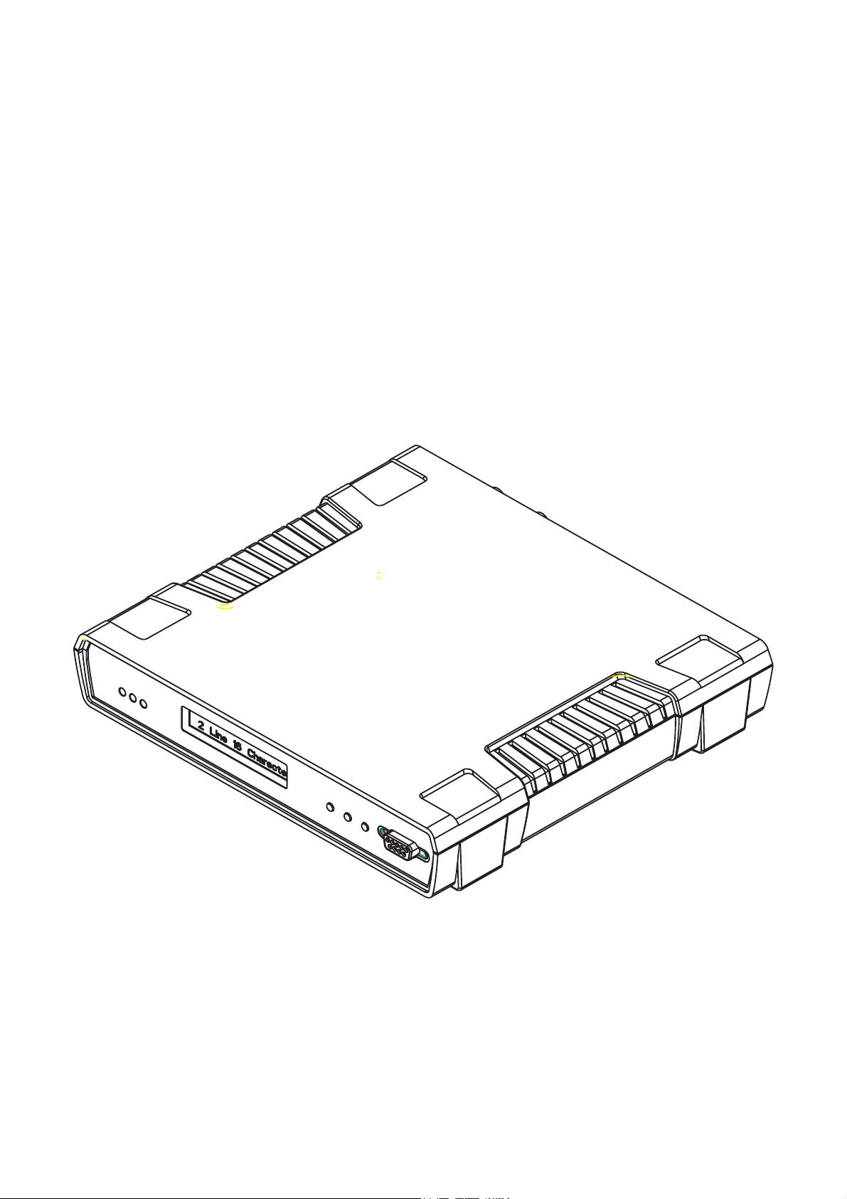
2 INTRODUCTION
The AM200 is a DSL modem that complies with the G.SHDSL standard for high-speed digital line technology.
It is capable of transmitting up to 7½ Km at 128kbps over 0.5mm2 cable (5.9Km at 2Mbps).
The AM200 supports transmission rates from 128kbps to 2.3Mbps over a single pair copper line.
The AM200 provides a combination of Ethernet, X21/V35 and G703 interface options. All of the interfaces
can be operated simultaneously. The X21 and V35 Interface options require the use of a special converter
cable that attaches to the 25 way D-type connector on the back of the AM200.
The Ethernet interface supports Routing and Bridging over PPP and Frame Relay. The Nx64 interface supports
data rates between 64kbps and 2.3Mbps. The Nx64 supports V35, X21 and RS530 user selectable interfaces.
Management control can be provided remotely via SNMP, Telnet, and Web Browser or locally via the RS232
connector. Alternatively the AM200 (LCD version) can be set-up locally using the menu/navigation buttons on
the front of the unit.
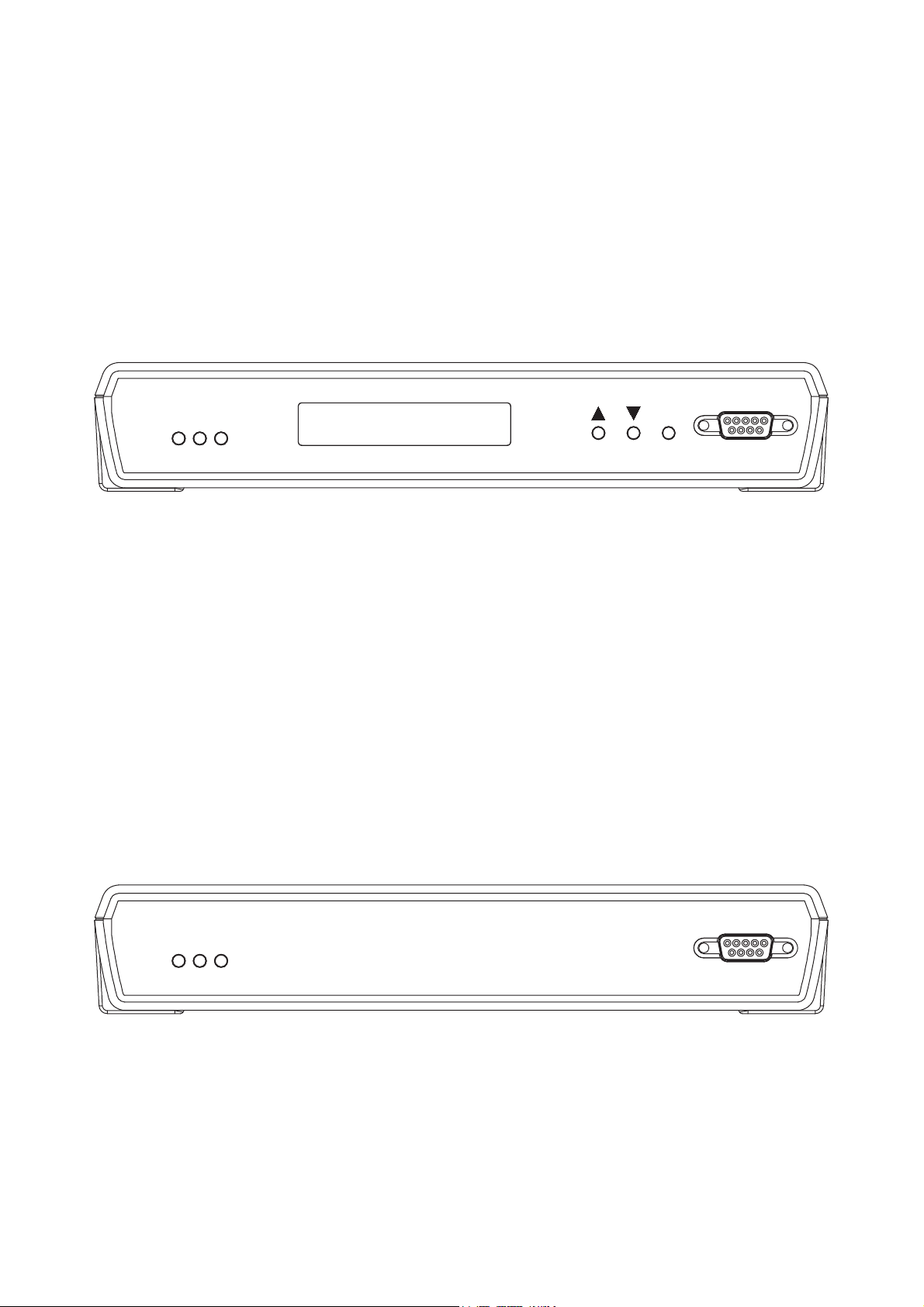
Figure 1 AM200 with LCD Display
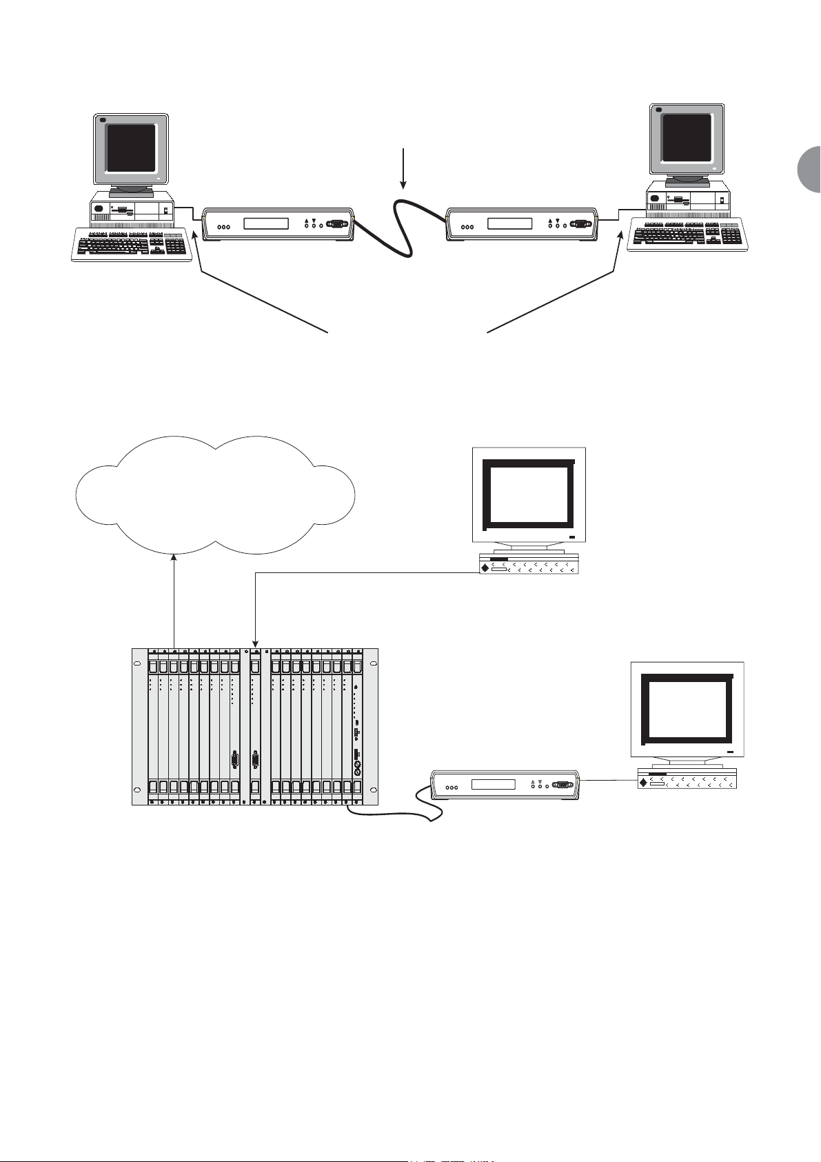
The AM200 can be connected back to back to give a cost effective high-speed data transfer link between two
sites.
ATL User Guide
AM200 Modem
13
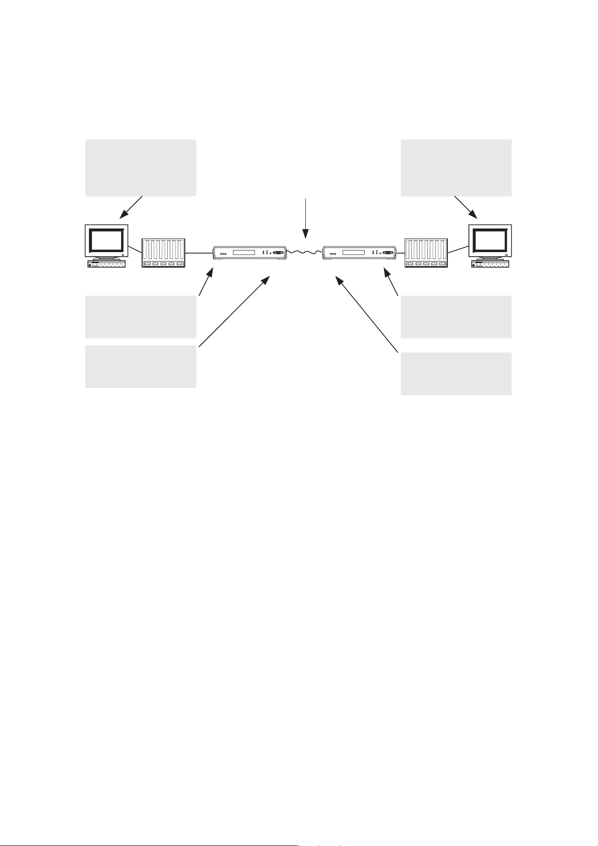
2
Figure 2 AM200 Back-to-Back connection
The AM200 is part of ATL's AM7000 family of products, which allows the unit to be linked to the AM7000
shelf. One AM7000 shelf can manage and serve up to 128 AM200 units.
Figure 3 AM200 to AM7000 Connection
1 Copper pair
AM200 AM200
atl
er
ine
Us
L
AM200
Test
Term
CO CPE
G703/X.21/V.35/RS530/
100BaseT
atl
User
Line
AM200
st
Te
Term
D.D.N.
(Digital Data Network)
Status
Status
Status
Status
Test
Test
Test
Test
Chan
Chan
Chan
Chan
atl
atl
atl
atl
AM7000
AM7000
AM7000
AM7000
AM7000
E1S16
E1S16
E1S16
E1S16
E1S16
Status
Status
Status
Test
Test
Chan
Chan
atl
atl
AM7000
AM7000
E1S16
E1S16
Status
Status
Status
Test
Test
Test
Test
Chan
Chan
Chan
Chan
Mngmt
Mngmt
Ether
Ether
Rmvd
Rmvd
atl
atl
atl
atl
AM7000
AM7000
AM7000
E1S16
AM7000
PMX
PMX
E1S16
10/100BaseT
SNMP Manager
Status
Status
Status
Status
Status
Status
Status
Test
Test
Test
Chan
Chan
Chan
atl
atl
atl
AM7000
AM7000
AM7000
E1S16
E1S16
E1S16
Status
Test
Test
Test
Test
Test
Chan
Chan
Chan
Chan
Chan
Status
Test
Alarm
Fuse A
Fuse B
atl
AM7000
E1S16
Power
atl
atl
atl
atl
AM7000
AM7000
AM7000
Fan Alarm
E1S16
E1S16
E1S16
PWR1
Fan Power
Fuse A
Fuse B
12.5A/250V
atl
AM200
Customer
Terminal
ATL User Guide
AM200 Modem
14
3 EXAMPLE APPLICATIONS
The following examples illustrate some of the applications.
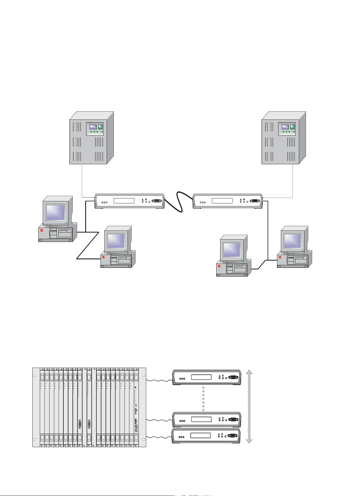
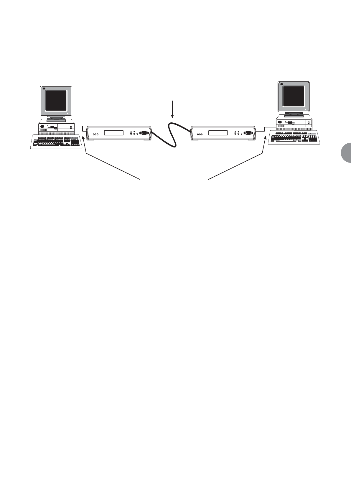
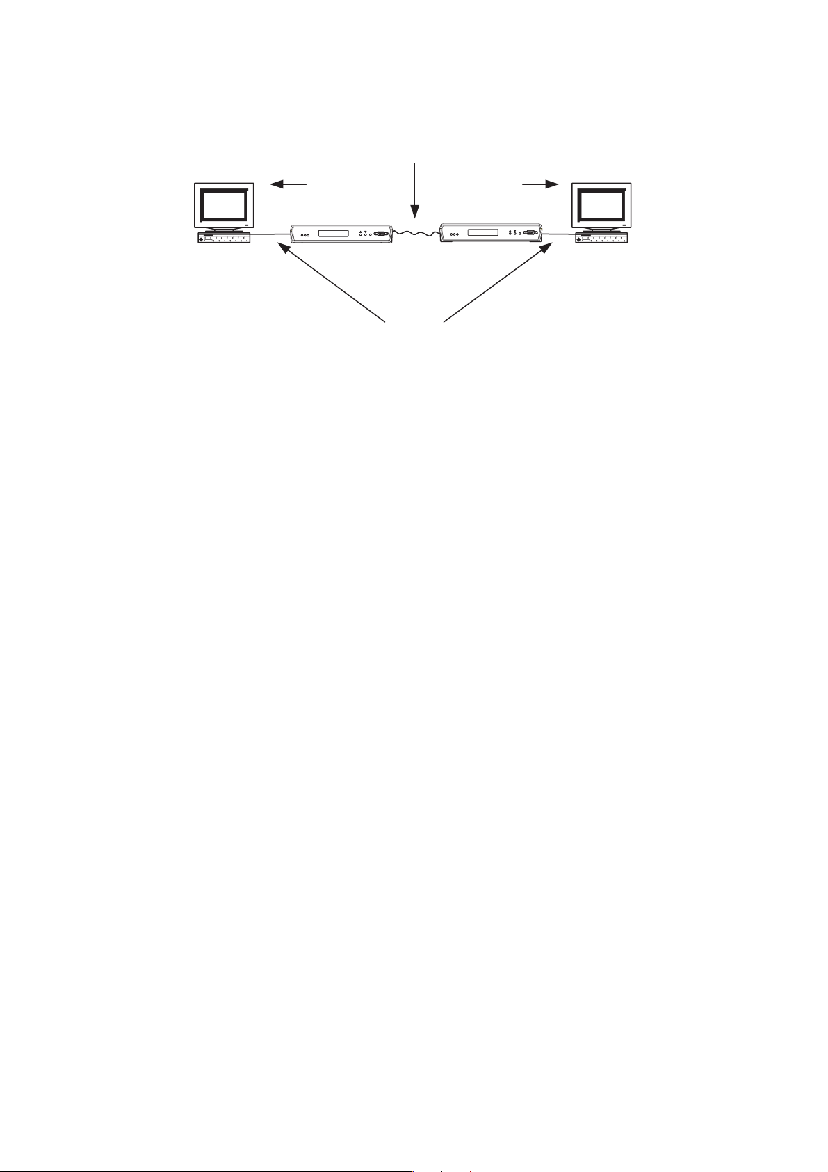
3.1 AM200 BACK TO BACK SET-UP (INTEGRATED VOICE & DATA TRANSMISSION)
Due to the flexibility of the AM200 DSL modem the unit can be connected back-to-back to give high-speed
integrated voice and data transmission between two sites.
Figure 4 Example showing PBX and LAN connection between two sites
3.2 AM200 TO AM200 CONNECTION VIA AN AM7000 MULTIPLEXER (CROSS
CONNECTION)
When the AM7000 Rack is fitted with a PMX Card plus 16 x DSL-8 Cards the DSL Access Multiplexer can cross
connect 128 x AM200 DSL Modems (Figure 5) operating from 128kbps up to 2.3Mbps.
Figure 5 AM200 cross-connection via an AM7000 Multiplexer
PBX
Line
User
atl AM200
AM200
Test
Term
Line
User
atl AM200
Test
AM200
Term
PBX
CO (master) CPE (slave)
LAN
LAN
AM7000 Access Multiplexer fitted with
16 DSL-8 Cards
Status
Status
Status
Status
Test
Chan
atl
AM7000
DSL8
Status
Test
Test
Test
Test
Chan
Chan
Chan
Chan
atl
atl
atl
atl
AM7000
AM7000
AM7000
AM7000
DSL8
DSL8
DSL8
DSL8
Status
Status
Status
Test
Test
Chan
Chan
atl
atl
AM7000
AM7000
DSL8
DSL8
Status
Status
Test
Test
Chan
Chan
Mngmt
Ether
Rmvd
atl
atl
AM7000
AM7000
PMX
DSL8
Status
Status
Status
Status
Status
Status
Status
Test
Test
Test
Test
Chan
Mngmt
Ether
Rmvd
atl
AM7000
PMX
Test
Chan
Chan
Chan
Chan
atl
atl
atl
atl
AM7000
AM7000
AM7000
AM7000
DSL8
DSL8
DSL8
DSL8
Status
Test
Test
Test
Test
Chan
Chan
Chan
Chan
Status
Test
Alarm
Fuse A
Fuse B
atl
AM7000
DSL8
Power
atl
atl
atl
AM7000
AM7000
AM7000
Fan Alarm
DSL8
DSL8
DSL8
PWR1
Fan Power
Fuse A
Fuse B
12.5A/250V
2.048Mbps
atl AM200
atl
AM200
atl AM200
Up to 128 AM200 DSL
Modems can be cross-
connected using 16 DSL-8
Line Cards
ATL User Guide
AM200 Modem
15
3
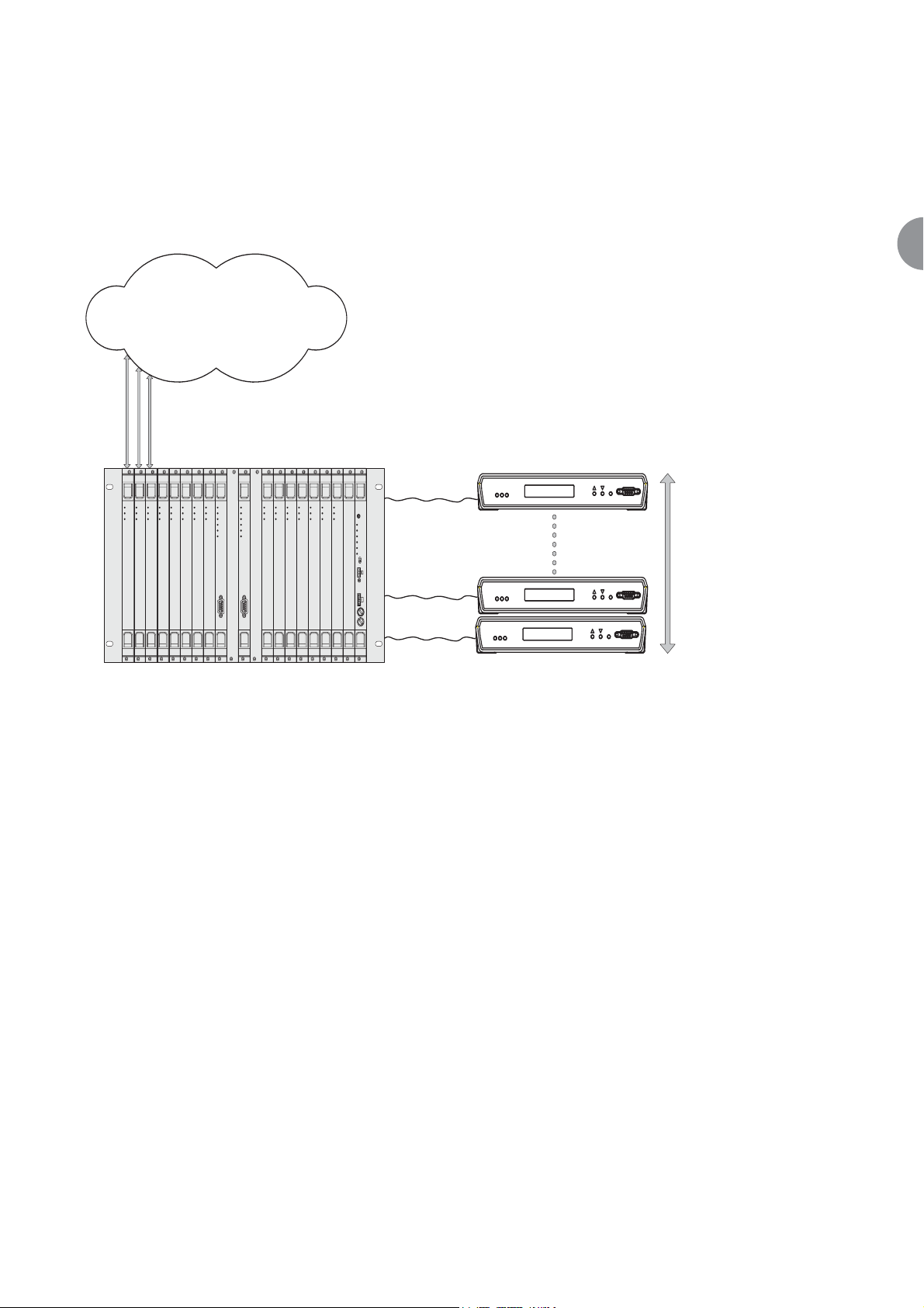
3.3 AM200 MODEMS CONNECTED TO A D.D.N. VIA AN AM7000 MULTIPLEXER AT
1.024MBPS
With the AM7000 Rack fitted with a PMX Card plus 12 x DSL-8 Cards and 3 x E1S-16 Cards the DSL Access
Multiplexer can support 96 x AM200 DSL Modems operating at 1.024Mbps with 48 x E1 Interfaces (Figure
6) giving connection to a Digital Data Network.
Figure 6 Example Connection to a AM7000 Multiplexer @ 1.024Mbps
D.D.N.
(Digital Data Network)
48 x E1
connections
Status
Status
Status
Status
Status
Test
Test
Test
Test
Test
Chan
Chan
Chan
Chan
Chan
atl
atl
atl
atl
AM7000
E1S16
atl
AM7000
AM7000
AM7000
AM7000
E1S16
E1S16
DSL8
DSL8
Status
Status
Test
Chan
atl
AM7000
AM7000
DSL8
Status
Status
Status
Test
Test
Test
Chan
Chan
Chan
Mngmt
Ether
Rmvd
atl
atl
atl
AM7000
AM7000
PMX
DSL8
DSL8
Status
Status
Status
Status
Status
Status
Test
Test
Test
Chan
Chan
Chan
Mngmt
Ether
Rmvd
atl
atl
atl
AM7000
AM7000
AM7000
AM7000
PMX
DSL8
DSL8
Status
Test
Test
Test
Test
Test
Chan
Chan
Chan
Chan
Chan
atl
atl
atl
atl
atl
AM7000
AM7000
AM7000
AM7000
DSL8
DSL8
DSL8
DSL8
DS8
AM7000 Access Multiplexer fitted with
12 DSL-8 & 3 E1S-16 Cards
atl AM200
Status
Test
Alarm
Fuse A
Fuse B
Power
Fan Alarm
PWR1
Fan Power
Fuse A
Fuse B
12.5A/250V
atl
AM200
Up to 96 AM200 DSL
Modems can be connected
atl AM200
1.024Mbps
ATL User Guide
AM200 Modem
16
4 CONSTRUCTION
The DSL modem is a desktop/wall mounting unit housed in a non-flammable plastic case (UL94 rating V0).
The unit can be mounted on a wall (optional wall bracket is required) or placed on a desk. The design allows
for a number of units to be stacked (if required). The AM200 can be purchased either with a LCD display
(AM200ALE) or without a LCD display (AM200AE).
4.1 AM200ALE FRONT PANEL
The front panel of the AM200ALE version contains a RS232 9 way D-Type Terminal connection and three
status LED's, plus three buttons and a menu driven 2 line 32-character LCD display.
LEDS
Test
User Port
Lines
Buttons
Up Arrow
Down Arrow
Select
4.2 AM200AE FRONT PANEL
The front panel of the AM200AE version contains a RS232 9 way D-Type Terminal connection and three
status LEDs.
LEDs
Test
User Port
Lines
Term
atl
User
Line
AM200
est
T
Select
AM200
atl
Line
User
est
T
Term
ATL User Guide
AM200 Modem
17
4
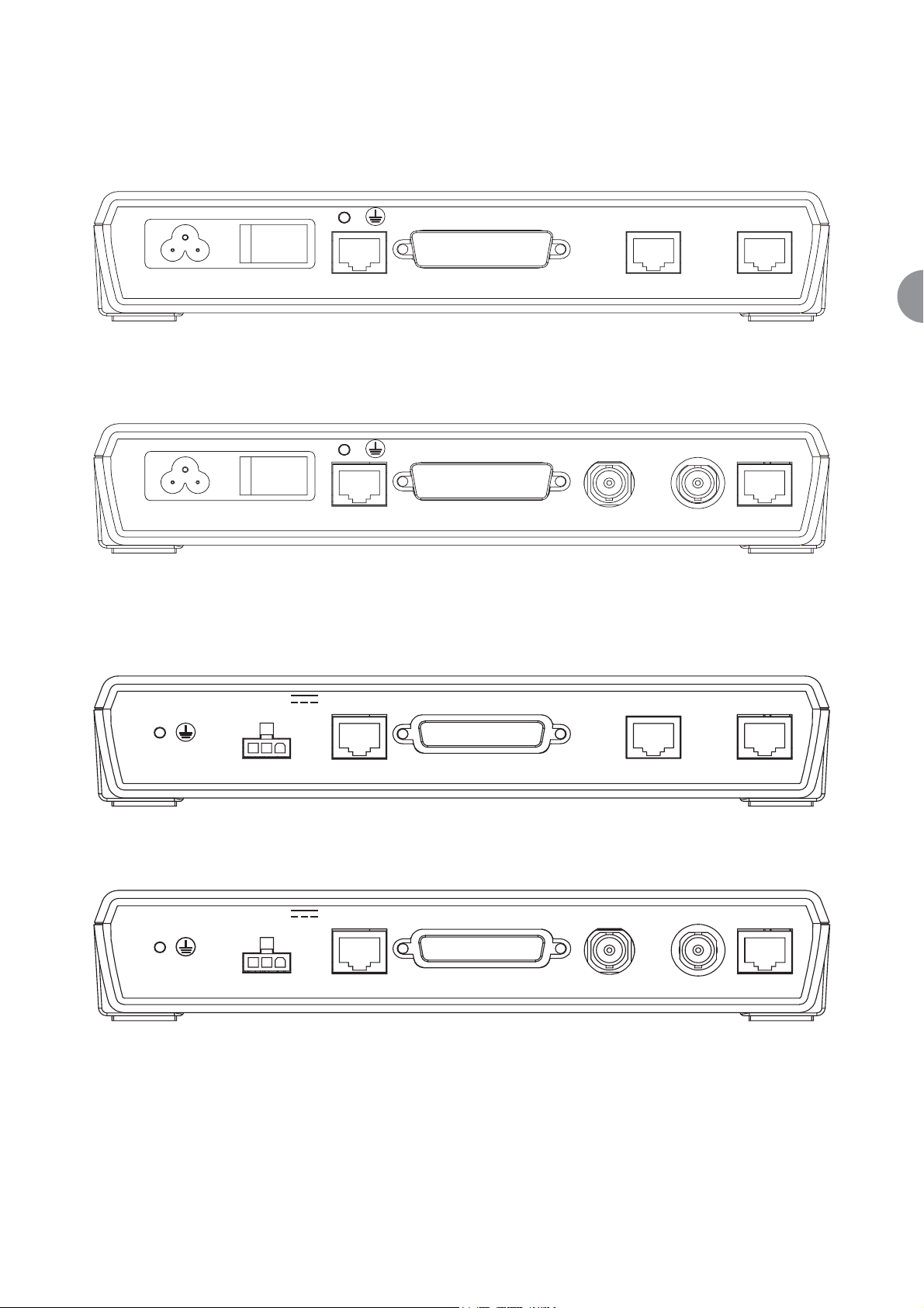
4.3 AM200 REAR PANEL
4.3.1 AC Variant 3-pin IEC mains inlet socket and switch
Figure 7 AM200 AC with 10/100BaseT, RS530 & G703 120 Ohm data ports
Figure 8 AM200 AC with 10/100BaseT, RS530 & G703 75 Ohm data ports
4.3.2 DC Variant
Figure 9 AM200 DC with 10/100BaseT, RS530 & G703 120 Ohm data ports
Figure 10 AM200 DC with 10/100BaseT, RS530 & G703 75 Ohm data ports
85-250V AC 100mA
85-250V AC 100mA
50-60Hz
50-60Hz
-18V to -72V
222mA
LINE
LINE
RS530/V35/X21
RS530/V35/X21
G703
TX RXG703
100 BaseT
100 BaseT
LINE
RS530/V35/X21
G703
100 BaseT
-18V to -72V
222mA
LINE
RS530/V35/X21
TX RXG703
100 BaseT

ATL User Guide
AM200 Modem
18
4.3.3 Rear Connectors Common to AC & DC Variants
RJ45 Line Interface
User Data Ports (depending on variant)
With LCD
AM200ALE 10/100BaseT RJ45
AM200ALEX 10/100BaseT + X21/V35 RJ45 + 25 way D type
AM200ALEG7 10/100BaseT + G703 75 ohms RJ45 + 2*BNC
AM200ALEG1 10/100BaseT + G703 120 ohms RJ45 + RJ45
Without LCD
AM200AE 10/100BaseT RJ45
AM200AEX 10/100BaseT + X21/V35 RJ45 + 25 way D type
AM200AEG7 10/100BaseT + G703 75 ohms RJ45 + 2*BNC
AM200AEG1 10/100BaseT + G703 120 ohms RJ45 + RJ45
CABLES
The X21 Data Port requires a 25way D Type to 15way D Type Converter cable.
The V35 Data Port requires a 25way D type to MRAC Converter cable.
Also included is a 2.0m mains lead fitted with a country variant mains plug (AC models only) and a 3 metre
screened Category 5 line cord terminated in 8-way RJ45 plugs at both ends

ATL User Guide
AM200 Modem
19
5
5 INSTALLATION
This chapter describes the basic steps that are required to set up a system using the AM200 DSL modem.
It is recommended that if two desktop units are to be connected they should be tested back to back to check
for operation before deployment.
5.1 CONNECTION OF PROTECTIVE EARTH
If a G703 port needs to be connected to a circuit that is defined as TNV, then a protective earth must be
connected to the earth bond stud on the rear panel. See the Safety Statements at the front of this User
Guide.
5.2 LED POWER ON SEQUENCE
The TEST LED is red during the boot sequence and self-test.
Followed by all LEDs flashing orange for 45 seconds.
Followed by normal operation.
5.3 LCD POWER ON SEQUENCE
On power-on, and after a button inactivity timeout, the LCD display will revert to a status display. The upper
LCD display line will show the product name, management mode and DSL mode, while the lower LCD display
line will show the DSL and userport states (Up, Errored, Down or Disabled) in rotation.
AM200:Master:Co
Line:Up
This display, and some of the 'Show' sub-menu items, is refreshed automatically every two seconds.
Pressing any one of the three buttons will wake-up the LCD.
5.4 DEFAULT SETTINGS

ATL User Guide
AM200 Modem
20
Mode NTU/CPE/RT
Line Rate Rate Adaptive
Management Mode Slave
Enable Line True
Expected Model (slave) AM200EXG
IP Interface
IP Address 10.254.254.253
Mask 255.255.0.0
Ethernet Port
Ethernet Port Enabled
User Rate Line Rate
Electrical IEEE 802.3 10 Base T/IEEE 802.3u (Fast Ethernet)
Nx64 Data Port
Nx64 Port Disabled (if fitted)
User Rate 0
Electrical V35
Mode DCE
Control Interchange circuits Clamped ON
G.703 Port
G.703 Port Disabled (if fitted)
User Rate 2048 kbps
Time Slots All Time slots Disabled
Frame E1 Framed with CRC enabled
ATL User Guide
AM200 Modem
21
6
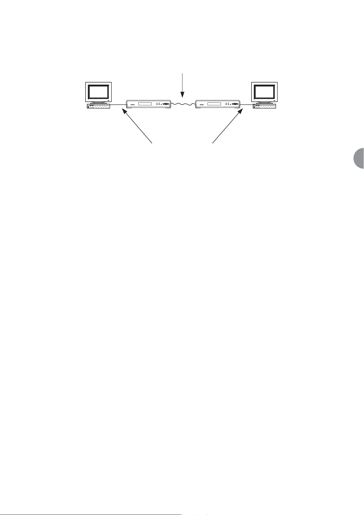
6 QUICK START GUIDE
This section of the manual is intended to allow the user to set up the AM200 in a simple point-to-point
configuration quickly, and simply.
Figure 11 Point-to-Point Configurations
Each of these configurations assumes that the AM200s start in the factory default configuration. The AM200
can be returned to its factory default state by using the following CLI command:
--> system config restore factory
↵↵
6.1 SET ONE END TO CO
All configurations require one AM200 to be configured as a CO, and the other as a CPE. AM200 defaults to
a CPE, so the first thing we must do is set one of the units to be a CO. This is done using the following CLI
command:
--> am200 set interface local dslmode co
↵↵
6.2 LINE RATE
By default AM200 will rate adapt to the highest line rate it can achieve on the line it is connected to. The rate
being used can be found by using the following command:
--> am200 show interface local currentlinerate
↵↵
Alternatively the line rate can be specified. The line rate should be set at the CO end only. See section 8.8 of
this manual for instructions on how to set the line rate.
1 Copper pair
AM200 AM200
atl
er
ine
Us
L
AM200
Test
Term
CO CPE
G703/X.21/V.35/RS530/
100BaseT
atl
User
Line
AM200
st
Te
Term
ATL User Guide
AM200 Modem
22
6.3 ETHERNET
6.3.1 CONFIGURATION AS A BRIDGE
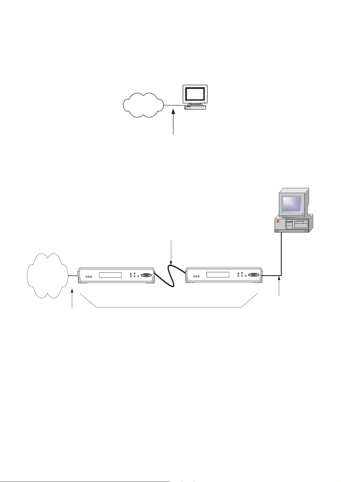
The User's PC and the Network are connected directly together and so must be on the same IP subnet.
Figure 12 AM200 to PC Connection
Figure 12 shows a PC connected to a local LAN. If the user wishes to connect a remote PC to the LAN then
a pair of AM200s may be used to bridge between them as shown in Figure 13.
Figure 13 AM200 Bridge
Bridging is the default mode of operation of the AM200.
Connect the AM200 over the transmission line to form the wide area link. Connect the LAN to the 'CO'
AM200 with a straight cable. Connect the PC to the 'CPE' AM200 with a crossover cable.
AM200s are supplied with a default address and subnet mask as follows.
IP address 10.254.254.253
Subnet Mask 255.0.0.0
The IP address of one of the AM200s will have to be changed so that the two don't clash. If the address
clashes with something else on the network then both will have to be changed.
LAN
User's
PC
10/100BaseT
Straight cable
User's PC
Network
atl
Line
User
AM200
leased line
AM200
Test
Term
Line
User
atl AM200
Test
CO
AM200
Term
CPE
10/100BaseT
Crossover cable
10/100BaseT
Straight cable
Wide Area
Link

ATL User Guide
AM200 Modem
23
6
To change the IP address use the following CLI command:
--> ip set interface iplan ipaddress <ipaddress> <netmask>
↵↵
Where <ipaddress> is the desired IP address, and <netmask> is the desired subnet mask.
6.3.2 CHANGING AN AM200 FROM ROUTER TO BRIDGE
Probably the quickest way to change an AM200 to be a Bridge is to restore the factory default settings as
described at the start of the section. Otherwise the following commands will configure the AM200 to be a
bridge.
First remove the router configuration. Type in:-
--> ip clear interfaces
↵↵
--> ip clear routes
↵↵
--> ip clear riproutes
↵↵
Then add interfaces for each side of the bridge, e.g. "lan" for the Ethernet user port and "wan" for the DSL
connection: Type in:-
--> bridge add interface lan
↵↵
--> bridge add interface wan
↵↵
Then attach the interfaces to the appropriate transports. Type in:
--> bridge attach lan ethernet
↵↵
--> bridge attach wan hdlc
↵↵
Finally to allow IP management of the unit, create an IP interface "iplan" and attach the bridge to the IP stack:
--> ip add interface iplan <ipaddress> <netmask>
↵↵
--> ip attachbridge iplan
↵↵
ATL User Guide
AM200 Modem
24
6.3.3 C0NFIGURATION AS A ROUTER
See the diagram below for an example configuration of AM200 being used as a router. AM200 defaults to
be a bridge, so first we must clear the bridge configuration. Type in:
--> bridge clear interfaces
↵↵
--> ip clear interfaces
↵↵
Then we add IP interfaces for each side of the router, e.g. "lan" (the Ethernet user port) and "wan" (the DSL
line interface).
--> ip add interface lan <ipaddress> <netmask>
↵↵
--> ip add interface wan <ipaddress> <netmask>
↵↵
For the example above the following commands would be used at the CO.
--> ip add interface lan 10.10.1.1 255.255.0.0
↵↵
--> ip add interface wan 192.168.1.1 255.255.0.0
↵↵
And at the CPE
--> ip add interface lan 10.11.1.1 255.255.0.0
↵↵
--> ip add interface wan 192.168.1.2 255.255.0.0
↵↵
Then attach the interfaces we have created to the appropriate transports.
--> ip attach lan ethernet
↵↵
--> ip attach wan hdlc
↵↵
PC
IP 10.10.0.1
Mask 255.255.0.0
Gateway 10.10.1.1
User's
PC
User Port
IP 10.10.1.1
Mask 255.255.0.0
Line
IP 192.168.1.1
Mask 255.255.0.0
Hub Hub
AM200
CO
leased line
AM200
CPE
PC
IP 10.11.18.8
Mask 255.255.0.0
Gateway 10.11.1.1
User's
PC
User Port
IP 10.11.1.1
Mask 255.255.0.0
Line
IP 192.168.1.2
Mask 255.255.0.0

ATL User Guide
AM200 Modem
25
6
Then, add a default route for the wan link using the command
--> ip add defaultroute gateway <ipaddress>
↵↵
For the example above the following commands would be used at the CO.
--> ip add defaultroute gateway 192.168.1.2
↵↵
And at the CPE
--> ip add defaultroute gateway 192.168.1.1
↵↵
Finally, add a route back to the connection on the LAN using the command:
--> ip add route <name> <subnet> <netmask> interface lan
↵↵
For the example above the following commands would be used at the CO.
--> ip add route route1 10.10.0.0 255.255.0.0 interface lan
↵↵
And at the CPE
--> ip add route route2 10.11.0.0 255.255.0.0 interface lan
↵↵
After doing these changes you must enter the following command and press the return key to store your
settings. Type in:
--> system config save Normal
↵↵
Note: Wait for the CLI confirmation message before you switch off the AM200.
ATL User Guide
AM200 Modem
26
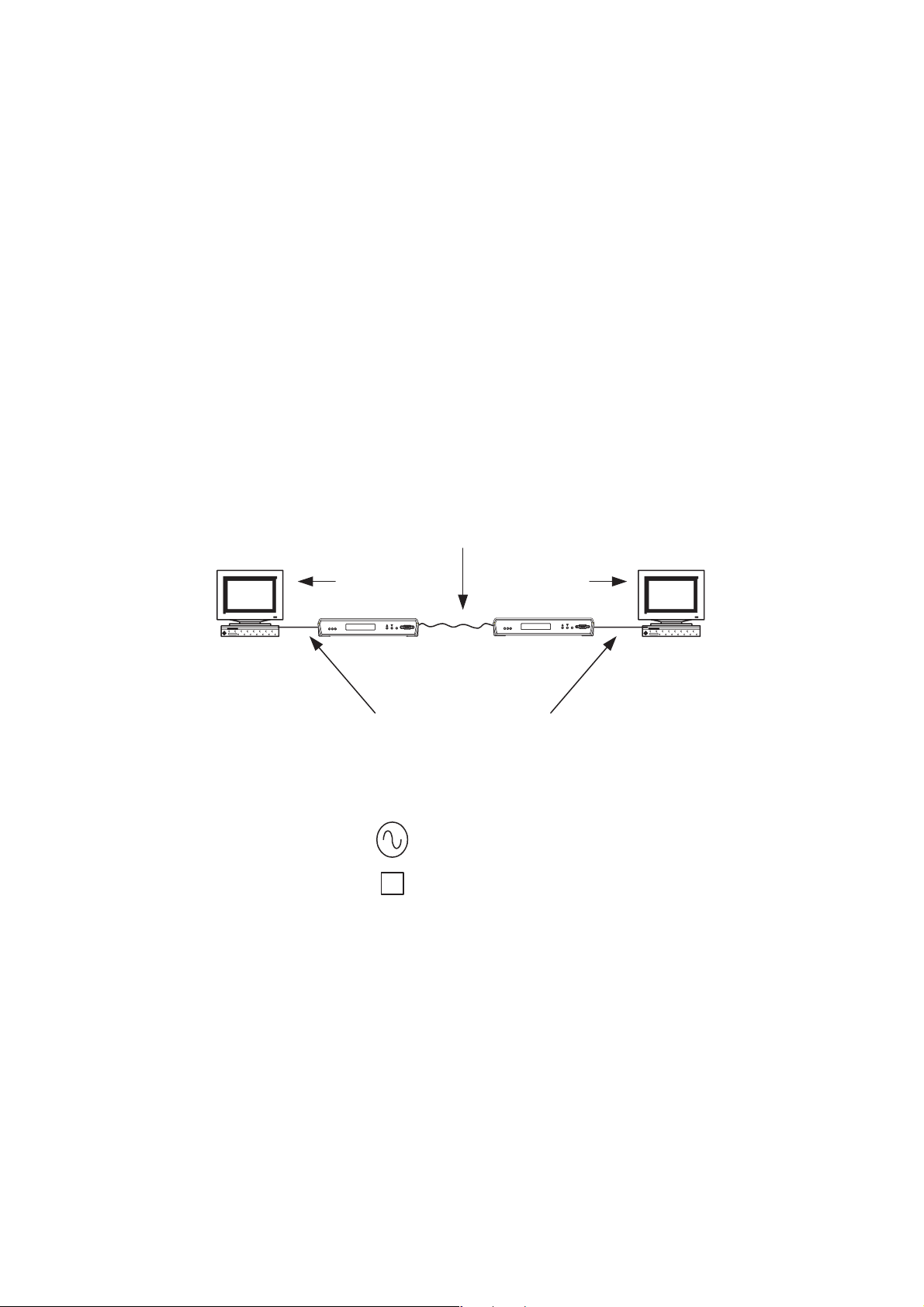
6.4 G703
To set up a G703 link. Start from factory default configuration. Set one unit to be a CO as described above.
Then on both units (CO and CPE) input the following commands.
First disable the Ethernet port, which is enabled by default. Type in:
--> hdlc set interface local adminstatus down
↵↵
--> hdlc set interface local ntimes64k 0
↵↵
Then enable the G703 port. Type in:
--> ds1 config set interface local adminstatus up
↵↵
--> ds1 config set interface local chanelization disabled
↵↵
This will enable G703 port in the following configuration
· E1 Framed mode
· AM200 as the timing master for the link (both CO and CPE set to local timing)
· All 32 timeslots active
Note. The current line rate must be 2048k or greater for this configuration to operate correctly
copper pair
timing timing
AM200
CPE
Customer
Terminal
Customer
Terminal
AM200
CO
G.703
ATL User Guide
AM200 Modem
27
6
6.5 NX64
To set up an Nx64 link. Start from factory default configuration. Set one unit to be a CO as described above.
Then on both units (CO and CPE) input the following commands.
First disable the Ethernet port, which is enabled by default. Type in:
--> hdlc set interface local adminstatus down
↵↵
--> hdlc set interface local ntimes64k 0
↵↵
Then enable the Nx64 port. Type in
--> nx64 set interface local adminstatus up
↵↵
--> nx64 set interface local ntimes64k linerate
↵↵
This will enable nx64 port in the following configuration
· V35 DCE interface
· Data rate equal to current line rate
copper pair
AM200
CPE
DCE
Customer
Terminal
Customer
Terminal
AM200
CO
DCE
X.21/V.35/RS530
ATL User Guide
AM200 Modem
28
7 SELECTING THE CIRCUIT CONFIGURATION
The term 'digital section' refers to the data link between the user ports of the connected AM200s.
In a standalone section, the AM200s provide the complete transmission system.
In a tandem section, the AM200s are used to extend an existing circuit or network port. To achieve
synchronous data transfer, the CO AM200 must derive its timing from the circuit to which it is connected.
A Point-to-Point link requires two AM200s, one CO and one CPE.
The AM200 at one end of the digital section is selected to be a CO; the remote end is selected to be a CPE.
For a tandem section, the AM200 connected to the tandem section is configured as the CO.
Please refer to the diagrams on the following pages.
7.1 STANDALONE SECTION
Key for following diagrams:
Customer
Terminal
copper pair
AM200A AM200A
CO CPE
G.703/X.21/V.35/RS530/100BaseT
Clock Source
B
Buffer
TimingTiming
Customer
Terminal
ATL User Guide
AM200 Modem
29
7
7.1.1 Internal Timing
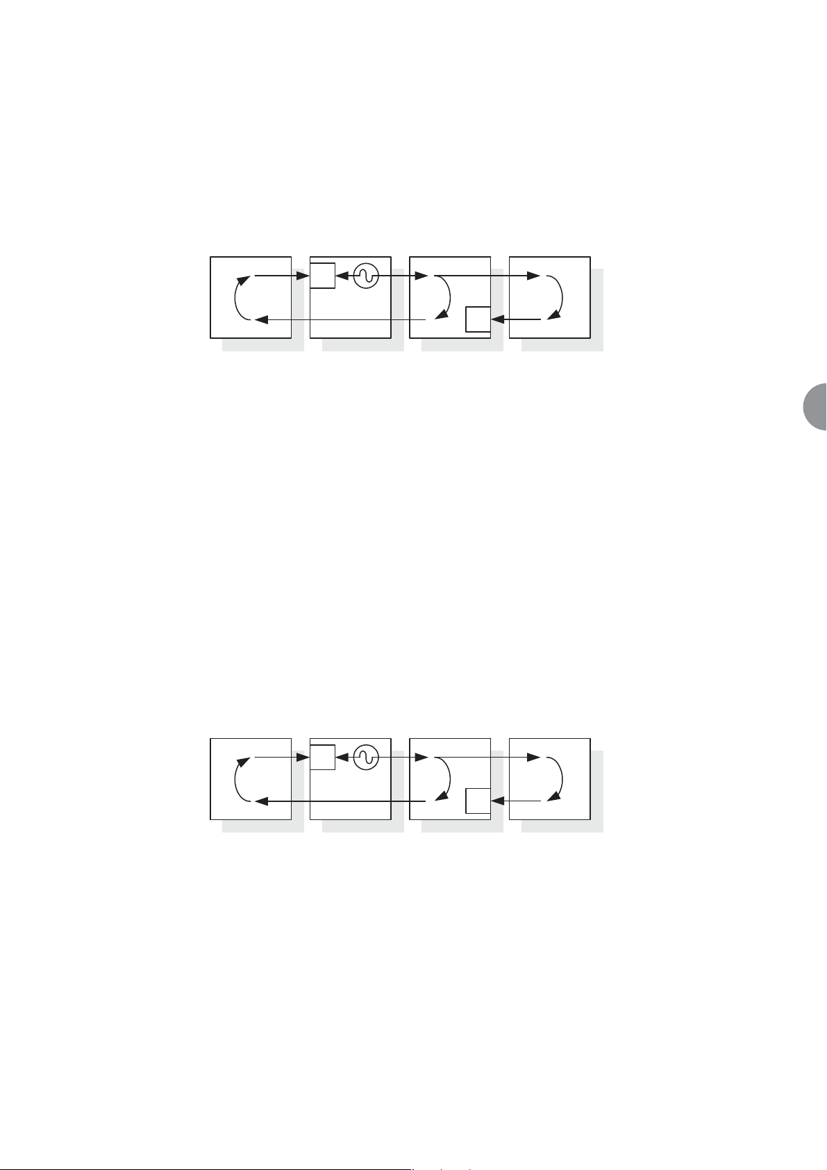
7.1.1.1 G.703 to G.703 Internal Timing Master
Slave terminals are connected to the digital section at both ends. The clock source inside the CO then
becomes the reference clock for the entire system.
The internal clock is generated at the CO. Both terminals lock to this clock and return the clock to the
AM200s. An elastic store in the AM200 buffers the data.
1. At the CO, select the 'Local' timing option for the G.703 port.
2. At the CPE, select the 'Local' timing option for the G.703 port.
This is the default timing mode for G.703.
7.1.1.2 G.703 to X.21/V.35 Internal Timing
Slave terminals are connected to the digital section at both ends. A clock inside the CO then becomes the
reference clock for the entire system.
The internal clock is generated at the CO. Both terminals lock to this clock and return the clock to the
AM200s. An elastic store in the AM200 buffers the data.
1. At the CO, select the 'Local' timing option for the G.703 port.
2. At the CPE, select the 'DCE' mode option for the Nx64 port.
Terminal Terminal
AM200
CO
AM200
CPE
B
B
G.703 G.703G.703G.703
Terminal Terminal
AM200
CO
AM200
CPE
B
B
G.703 Nx64 DTENx64 DCEG.703
ATL User Guide
AM200 Modem
30
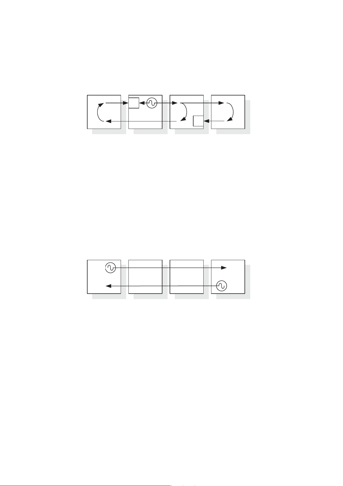
7.1.1.3 X.21/V.35 DCE to X.21/V.35 DCE
The terminals connected to the digital section at both ends are DTEs. A clock inside the CO then becomes the
reference clock for the entire system.
1. At the CO, select the 'DCE' timing option for the Nx64 port.
2. At the CPE, select the 'DCE' mode option for the Nx64 port.
This is the default timing mode for Nx64.
7.1.2 G.703 to G.703 Transparent Timing
In this configuration, the terminals are the source of timing. One of the connected terminals may act as a
master, the other as a slave. However, both terminals could operate independently or plesiochronously.
Clocks T1 and T2 are independent of one another and are transported independently through the DSL system.
1. At the CO, select the 'Through' timing option for the G.703 port.
2. At the CPE, select the 'Through' timing option for the G.703 port.
Terminal Terminal
AM200
CO
AM200
CPE
B
B
Nx64 DCENx64 DTE
Nx64 DTENx64 DCE
Master
Terminal
AM200
CO
AM200
CPE
Slave
Terminal
T1
T2
G.703 G.703G.703G.703
 Loading...