


 Loading...
V-series P5G41H
ASUS PC (Desktop Barebone)
User’s Manual

E4613
First Edition V1
April 2009
Copyright © 2009 ASUSTeK Computer Inc. All Rights Reserved.
No part of this manual, including the products and software described in it, may be reproduced, transmitted, transcribed, stored in a retrieval system, or translated into any language in any form or by any means, except documentation kept by the purchaser for backup purposes, without the express written permission of ASUSTeK Computer Inc. (“ASUS”).
Product warranty or service will not be extended if: (1) the product is repaired, modified or altered, unless such repair, modification of alteration is authorized in writing by ASUS; or (2) the serial number of the product is defaced or missing.
ASUS PROVIDES THIS MANUAL “AS IS” WITHOUT WARRANTY OF ANY KIND, EITHER EXPRESS OR IMPLIED, INCLUDING BUT NOT LIMITED TO THE IMPLIED WARRANTIES OR CONDITIONS OF MERCHANTABILITY OR FITNESS FOR A PARTICULAR PURPOSE. IN NO EVENT SHALL ASUS, ITS DIRECTORS, OFFICERS, EMPLOYEES OR AGENTS BE LIABLE FOR ANY INDIRECT, SPECIAL, INCIDENTAL, OR CONSEQUENTIAL DAMAGES (INCLUDING DAMAGES FOR LOSS OF PROFITS, LOSS OF BUSINESS, LOSS OF USE OR DATA, INTERRUPTION OF BUSINESS AND THE LIKE), EVEN IF ASUS HAS BEEN ADVISED OF THE POSSIBILITY OF SUCH DAMAGES ARISING FROM ANY DEFECT OR ERROR IN THIS MANUAL OR PRODUCT.
SPECIFICATIONS AND INFORMATION CONTAINED IN THIS MANUAL ARE FURNISHED FOR INFORMATIONAL USE ONLY, AND ARE SUBJECT TO CHANGE AT ANY TIME WITHOUT NOTICE, AND SHOULD NOT BE CONSTRUED AS A COMMITMENT BY ASUS. ASUS ASSUMES NO RESPONSIBILITY OR LIABILITY FOR ANY ERRORS OR INACCURACIES THAT MAY APPEAR IN THIS MANUAL, INCLUDING THE PRODUCTS AND SOFTWARE DESCRIBED IN IT.
Products and corporate names appearing in this manual may or may not be registered trademarks or copyrights of their respective companies, and are used only for identification or explanation and to the owners’ benefit, without intent to infringe.
ii

Table of contents
Notices.......................................................................................................... |
vi |
Safety information...................................................................................... |
vii |
About this guide........................................................................................ |
viii |
System package contents............................................................................ |
x |
Chapter 1: System introduction
1.1 |
Welcome!....................................................................................... |
1-2 |
|
1.2 |
Front panel .................................................................................... |
1-2 |
|
|
1.2.1 |
V2-P5G41H front panel ................................................. |
1-2 |
|
1.2.2 |
V6-P5G41H front panel................................................... |
1-3 |
1.3 |
Rear panel...................................................................................... |
1-5 |
|
|
Voltage selector.............................................................................. |
1-7 |
|
1.4 |
Internal components..................................................................... |
1-8 |
|
1.5 |
Qualified Vendors Lists (QVL)..................................................... |
1-9 |
|
Chapter 2: Starting up
2.1 |
Installing an operating system.................................................... |
2-2 |
|
2.2 |
Powering up................................................................................... |
2-2 |
|
2.3 |
Support DVD information............................................................. |
2-2 |
|
|
2.3.1 |
Running the support DVD................................................ |
2-3 |
|
2.3.2 |
Utilities menu................................................................... |
2-4 |
|
2.3.3 |
Manual menu................................................................... |
2-6 |
|
2.3.4 |
ASUS Contact information............................................... |
2-7 |
|
2.3.5 |
Other information............................................................. |
2-8 |
2.4 |
Software information.................................................................. |
2-10 |
|
|
2.4.1 |
ASUS AI Manager......................................................... |
2-10 |
|
2.4.2 |
ASUS Express Gate...................................................... |
2-16 |
Chapter 3: Motherboard info
3.1 |
Introduction................................................................................... |
3-2 |
3.2 |
Motherboard layout....................................................................... |
3-2 |
3.3 |
Jumpers......................................................................................... |
3-3 |
3.4 |
Connectors.................................................................................... |
3-5 |
iii

Table of contents
Chapter 4: BIOS setup
4.1 |
Managing and updating your BIOS............................................. |
4-2 |
|
|
4.1.1 |
ASUS Update utility......................................................... |
4-2 |
|
4.1.2 |
ASUS EZ Flash 2 utility................................................... |
4-5 |
|
4.1.3 |
ASUS CrashFree BIOS 3 utility....................................... |
4-6 |
4.2 |
BIOS setup program..................................................................... |
4-7 |
|
|
4.2.1 |
BIOS menu screen.......................................................... |
4-8 |
|
4.2.2 |
Menu bar......................................................................... |
4-8 |
|
4.2.3 |
Navigation keys............................................................... |
4-8 |
|
4.2.4 |
Menu items...................................................................... |
4-9 |
|
4.2.5 |
Sub-menu items.............................................................. |
4-9 |
|
4.2.6 |
Configuration fields.......................................................... |
4-9 |
|
4.2.7 |
Pop-up window................................................................ |
4-9 |
|
4.2.8 |
Scroll bar......................................................................... |
4-9 |
|
4.2.9 |
General help.................................................................... |
4-9 |
4.3 |
Main menu................................................................................... |
4-10 |
|
|
4.3.1 |
System Time ................................................................. |
4-10 |
|
4.3.2 |
System Date ................................................................. |
4-10 |
|
4.3.3 |
Primary IDE Master/Slave, SATA1~4............................. |
4-11 |
|
4.3.4 |
Storage Configuration.................................................... |
4-12 |
|
4.3.5 |
System Information........................................................ |
4-13 |
4.4 |
Advanced menu.......................................................................... |
4-14 |
|
|
4.4.1 |
JumperFree Configuration............................................. |
4-14 |
|
4.4.2 |
CPU Configuration......................................................... |
4-17 |
|
4.4.3 |
Chipset.......................................................................... |
4-18 |
|
4.4.4 |
Onboard Devices Configuration.................................... |
4-21 |
|
4.4.5 |
USB Configuration......................................................... |
4-22 |
|
4.4.6 |
PCI PnP......................................................................... |
4-23 |
4.5 |
Power menu................................................................................. |
4-24 |
|
|
4.5.1 |
Suspend Mode ............................................................. |
4-24 |
|
4.5.2 |
ACPI 2.0 Support .......................................................... |
4-24 |
|
4.5.3 |
ACPI APIC Support ...................................................... |
4-24 |
|
4.5.4 |
APM Configuration........................................................ |
4-25 |
|
4.5.5 |
Hardware Monitor.......................................................... |
4-26 |
iv

Table of contents
4.6 |
Boot menu................................................................................... |
4-27 |
|
|
4.6.1 |
Boot Device Priority....................................................... |
4-27 |
|
4.6.2 |
Boot Settings Configuration........................................... |
4-28 |
|
4.6.3 |
Security.......................................................................... |
4-29 |
4.7 |
Tools menu.................................................................................. |
4-31 |
|
|
4.7.1 ASUS EZ Flash 2.......................................................... |
4-31 |
|
|
4.7.2 |
Express Gate................................................................. |
4-32 |
|
4.7.3 |
AI NET 2........................................................................ |
4-32 |
4.8 |
Exit menu..................................................................................... |
4-33 |
|

Notices
Federal Communications Commission Statement
This device complies with Part 15 of the FCC Rules. Operation is subject to the following two conditions:
•This device may not cause harmful interference, and
•This device must accept any interference received including interference that may cause undesired operation.
This equipment has been tested and found to comply with the limits for a Class B digital device, pursuant to Part 15 of the FCC Rules. These limits are designed to provide reasonable protection against harmful interference in a residential installation. This equipment generates, uses and can radiate radio
frequency energy and, if not installed and used in accordance with manufacturer’s instructions, may cause harmful interference to radio communications. However, there is no guarantee that interference will not occur in a particular installation. If this equipment does cause harmful interference to radio or television reception, which can be determined by turning the equipment off and on, the user is encouraged to try to correct the interference by one or more of the following measures:
•Reorient or relocate the receiving antenna.
•Increase the separation between the equipment and receiver.
•Connect the equipment to an outlet on a circuit different from that to which the receiver is connected.
•Consult the dealer or an experienced radio/TV technician for help.
WARNING! The use of shielded cables for connection of the monitor to the graphics card is required to assure compliance with FCC regulations. Changes or modifications to this unit not expressly approved by the party responsible for compliance could void the user’s authority to operate this equipment.
Canadian Department of Communications Statement
This digital apparatus does not exceed the Class B limits for radio noise emissions from digital apparatus set out in the Radio Interference Regulations of the Canadian Department of Communications.
This class B digital apparatus complies with Canadian ICES-003.
REACH
Complying with the REACH (Registration, Evaluation, Authorisation, and Restriction of Chemicals) regulatory framework, we published the chemical substances in our products at ASUS REACH website at http://green.asus.com/english/REACH.htm.
vi

Safety information
Electrical safety
•To prevent electrical shock hazard, disconnect the power cable from the electrical outlet before relocating the system.
•When adding or removing devices to or from the system, ensure that the power cables for the devices are unplugged before the signal cables are connected.
•If the power supply is broken, do not try to fix it by yourself. Contact a qualified service technician or your retailer.
Operation safety
•Before installing devices into the system, carefully read all the documentation that came with the package.
•Before using the product, make sure all cables are correctly connected and the power cables are not damaged. If you detect any damage, contact your dealer immediately.
•To avoid short circuits, keep paper clips, screws, and staples away from connectors, slots, sockets and circuitry.
•Avoid dust, humidity, and temperature extremes. Do not place the product in any area where it may become wet. Place the product on a stable surface.
•If you encounter technical problems with the product, contact a qualified service technician or your retailer.
•We recommend that you use this product in environments with an ambient temperature below 35ºC.
Lithium-Ion Battery Warning
CAUTION: Danger of explosion if battery is incorrectly replaced. Replace only with the same or equivalent type recommended by the manufacturer.
Dispose of used batteries according to the manufacturer’s instructions.
VORSICHT: Explosionsgetahr bei unsachgemäßen Austausch der Batterie.
Ersatz nur durch denselben oder einem vom Hersteller empfohlenem
ähnljchen Typ. Entsorgung gebrauchter Batterien nach Angaben des Herstellers.
LASER PRODUCT WARNING
CLASS 1 LASER PRODUCT
vii

DO NOT throw the motherboard in municipal waste. This product has been designed to enable proper reuse of parts and recycling. This symbol of the crossed out wheeled bin indicates that the product (electrical and electronic equipment) should not be placed in municipal waste. Check local regulations for disposal of electronic products.
DO NOT throw the mercury-containing button cell battery in municipal waste. This symbol of the crossed out wheeled bin indicates that the battery should not be placed in municipal waste.
About this guide
Audience
This guide provides general information and installation instructions about the ASUS Vintage V-series P5G41H barebone system. This guide is intended for experienced users and integrators with hardware knowledge of personal computers.
How this guide is organized
This guide contains the following parts:
1.Chapter 1: System introduction
This chapter gives a general description of the ASUS
V-series P5G41H. The chapter lists the system features, including introduction on the front and rear panel, and internal components.
2.Chapter 2: Starting up
This chapter helps you power up the system and install drivers and utilities from the support DVD.
3.Chapter 3: Motherboard info
This chapter gives information about the motherboard that comes with the system. This chapter includes the motherboard layout, jumper settings, and connector locations.
4.Chapter 4: BIOS setup
This chapter tells how to change system settings through the BIOS Setup menus and describes the BIOS parameters.
viii

Conventions used in this guide
WARNING: Information to prevent injury to yourself when trying to complete a task.
CAUTION: Information to prevent damage to the components when trying to complete a task.
IMPORTANT: Instructions that you MUST follow to complete a task.
NOTE: Tips and additional information to aid in completing a task.
Where to find more information
Refer to the following sources for additional information and for product and software updates.
1.ASUS Websites
The ASUS websites worldwide provide updated information on ASUS hardware and software products. Refer to the ASUS contact information.
2.Optional Documentation
Your product package may include optional documentation, such as warranty flyers, that may have been added by your dealer. These documents are not part of the standard package.
ix
System package contents
Check your V-series P5G41H system package for the following items.
If any of the items is damaged or missing, contact your retailer immediately.
Item description
1.ASUS V-series P5G41H barebone system with
•ASUS motherboatd
•Power supply unit
•ASUS chassis
2.Cable
•AC power cable
3.Support DVD
4.Quick Installation Guide
5.Telecom Adapter Card (Optional)
Chapter 1
This chapter gives a general description of the ASUS
V-series P5G41H. The chapter lists the system features including introduction on the front and rear panel, and internal components.
System introduction
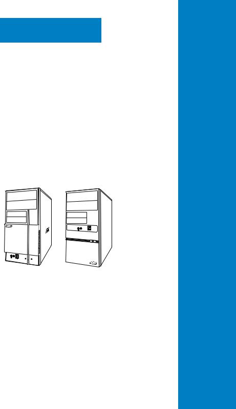
1.1Welcome!
Thank you for choosing the ASUS V-series P5G41H!
The ASUS V-series P5G41H is an all-in-one barebone system with a versatile home entertainment feature.
The system comes in a stylish casing and powered by the ASUS motherboard that supports the Intel® Core™2 Extreme / Core™2 Duo / Core™2 Quad / Pentium® dual-core / Celeron® processors in the 775-land package.
The system supports up to 8 GB of system memory using DDR2-1066/800/667 DIMMs. High-resolution graphics via integrated graphics controller or PCI Express x16 slot, Serial ATA, USB 2.0, and 8-channel audio feature the system and take you ahead in the world of power computing.
1.2Front panel
The front panel includes the optical drive bays, power button, and several I/O ports are located at the front panel.
1.2.1V2-P5G41H front panel
1 |
2 |
3 |
4 |
5 |
6 |
7 |
8 |
1-2 |
Chapter 1: System introduction |
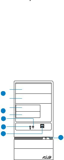
1.Two empty 5.25-inch drive bays. These bays are for 5.25-inch IDE/SATA optical drives.
2.Two empty 3.5-inch drive bays. These bays are for 3.5-inch hard disk drives.
3.Power button. Press this button to turn the system on.
4.Reset button. Press this button to reboot the system without turning off the power.
5.HDD LED. This LED lights up when data is read from or written to the hard disk drive.
6.USB 2.0 ports. These Universal Serial Bus 2.0 (USB 2.0) ports are available for connecting USB 2.0 devices such as a mouse, printer, scanner, camera, PDA, and others.
7.Headphone port. This Line In (lime) port connects a headphone with a stereo mini-plug.
8.Microphone port. This Mic (pink) port connects a microphone.
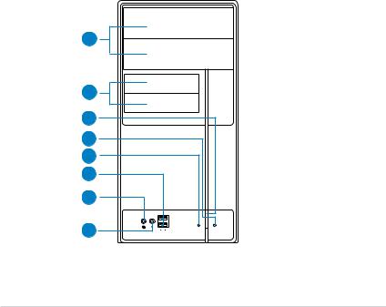
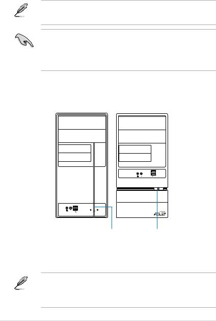
1.2.2V6-P5G41H front panel
10
11
12
13
14
15
|
|
|
|
|
|
ASUS V-series P5G41H |
1-3 |
||||

10.Two empty 5.25-inch drive bays. These bays are for 5.25-inch IDE/SATA optical drives.
11.Two empty 3.5-inch drive bays. These bays are for 3.5-inch hard disk drives.
12.Microphone port. This Mic (pink) port connects a microphone.
13.Headphone port. This Line In (lime) port connects a headphone with a stereo mini-plug.
14.USB 2.0 ports. These Universal Serial Bus 2.0 (USB 2.0) ports are available for connecting USB 2.0 devices such as a mouse, printer, scanner, camera, PDA, and others.
15.Power button. Press this button to turn the system on.
This V-series provide V2/V6 two types of front panel for users to choose, please refer to your product package for the front panel type you purchased.
1-4 |
Chapter 1: System introduction |

1.3Rear panel
The system rear panel includes the power connector and several I/O ports that allow convenient connection of devices.
1
2
6
7
8
9
10
12
14
15
16
17
3
4
5
HDMI |
OUT SPDIF |
DVI |
|
11
13
18
19
20
Do NOT cover the rear vent , and the ambient temperature is limited up to 35oC to prevent the system from overheating.
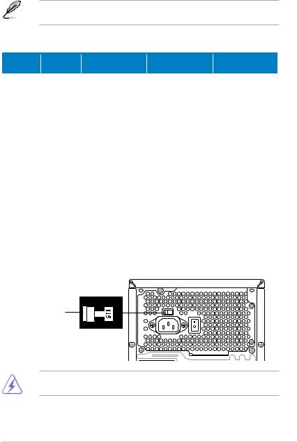
1.Voltage selector. This switch allows you to adjust the system input voltage according to the voltage supply in your area. See the section “Voltage selector” on page 1-7 before adjusting this switch.
2.Power connector. This connector is for the power cable and plug.
3.Power supply unit fan vent. This vent is for the PSU fan that provides ventilation inside the power supply unit.
ASUS V-series P5G41H |
1-5 |
4.Power Switch. This switch is for switching on/off the power supply unit.
5.Chassis fan vent. This vent is for the fan that provides ventilation inside the system chassis.
6.PS/2 mouse port. This green 6-pin connector is for a PS/2 mouse.
7.PS/2 keyboard port. This purple 6-pin connector is for a PS/2 keyboard.
8.Optical S/PDIF Out port. This port connects an external audio output device via an optical S/PDIF cable.
9.HDMI port. This port is for a High-Definition Multimedia Interface (HDMI) connector, and is HDCP compliant allowing playback of HD DVD, Blu-Ray and other protected content.
10.DVI-D Out port. This port is for any DVI-D compatible device and is HDCP compliant allowing playback of HD DVD, Blu-Ray and other protected content.
11.Video Graphics Adapter (VGA) port. This 15-pin port is for a VGA monitor or other VGA-compatible devices.
12.USB 2.0 ports 1 ~ 4. These 4-pin Universal Serial Bus (USB) ports are available for connecting USB 2.0 devices.
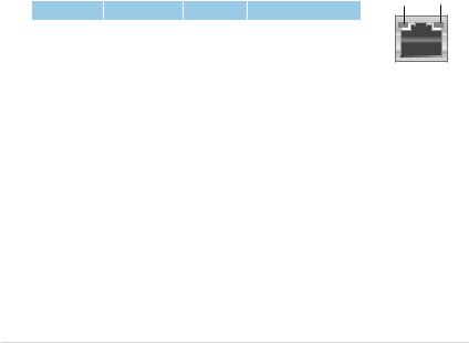
13.LAN (RJ-45) port. This port allows gigabit connection to a Local Area Network (LAN) through a network hub. Refer to the table below for the LAN port LED indications.
LAN port LED indications
|
Activity/Link |
|
Speed LED |
|
Status |
|
Description |
Status |
Description |
OFF |
|
No link |
OFF |
10 Mbps connection |
ORANGE |
|
Linked |
ORANGE |
100 Mbps connection |
BLINKING |
|
Data activity |
GREEN |
1 Gbps connection |
ACT/LINK SPEED LED LED
LAN port |
14.Rear Speaker Out port (black). This port connects the rear speakers in a
4-channel, 6-channel, or 8-channel audio configuration.
15.Side Speaker Out port (gray). This port connects the side speakers in an
8-channel audio configuration.
16.Microphone port (pink). This port connects a microphone.
17.Line Out port (lime). This port connects a headphone or a speaker. In
4-channel, 6-channel, and 8-channel configuration, the function of this port becomes Front Speaker Out.
18.Center/Subwoofer port (orange). This port connects the center/subwoofer speakers.
1-6 |
Chapter 1: System introduction |
19.Line In port (light blue). This port connects the tape, CD, DVD player, or other audio sources.
Refer to the audio configuration table below for the function of the audio ports in 2, 4, 6, or 8-channel configuration.
Audio 2, 4, 6, or 8-channel configuration
Port |
Headset. |
4-channel |
6-channel |
8-channel |
|
2-channel |
|||||
|
|
|
|
||
Light Blue |
Line In |
Line In |
Line In |
Line In |
|
Lime |
Line Out |
Front Speaker Out |
Front Speaker Out |
Front Speaker Out |
|
Pink |
Mic In |
Mic In |
Mic In |
Mic In |
|
Orange |
– |
– |
Center/Subwoofer |
Center/Subwoofer |
|
Black |
– |
Rear Speaker Out |
Rear Speaker Out |
Rear Speaker Out |
|
Gray |
– |
– |
– |
Side Speaker Out |
20.Expansion slot covers. Remove these covers when installing expansion cards.
Voltage selector
The PSU has a 115 V/230 V voltage selector switch located beside the power connector. Use this switch to select the appropriate system input voltage according to the voltage supply in your area.
If the voltage supply in your area is 100 127 V, set this switch to 115 V. If the voltage supply in your area is 200 240 V, set this switch to 230 V.
115V/230V |
Voltage selector |
Setting the switch to 115V in a 230V environment or 230V in a 115V environment will seriously damage the system!
ASUS V-series P5G41H |
1-7 |
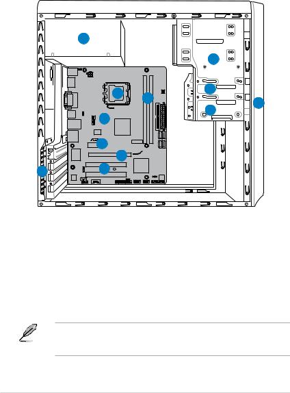
1.4Internal components
The illustration below is the internal view of the system when you remove the side cover and the power supply unit. The installed components are labeled for your reference.
5
|
|
2 |
|
6 |
7 |
3 |
|
1 |
|||
|
|||
|
|
||
|
|
4 |
8
|
10 |
|
P5QPL- 9 |
12 |
11 |
1. |
Front panel cover |
8. |
ASUS motherboard |
2. |
5.25-inch optical drive bays |
9. |
PCI Express x16 slot |
3. |
3.5-inch drive bay |
10. |
PCI Express x1 slot |
4. |
Hard disk drive bay |
11. |
PCI slots |
5. |
Power supply unit |
12. |
Metal bracket lock |
6.CPU socket
7.DIMM sockets
Refer to the bundled Quick Installation Guide for installing additional system components and get assistance from professionals when you disassemble or assemble the system.
1-8 |
Chapter 1: System introduction |

1.5Qualified Vendors Lists (QVL)
DDR2-1066MHz capability
|
|
|
SS/ |
Chip |
|
|
DIMM |
||
Vendor |
Part No. |
Size |
Chip NO. |
CL |
support |
||||
DS |
Brand |
A* |
B* |
||||||
|
|
|
|
|
|||||
|
|
|
|
|
|
|
|||
A-Data |
AD21066E002GU |
4096MB(2 x 2048MB) |
DS |
N/A |
Heat-Sink Package |
5-5-5-15 |
• |
• |
|
Apacer |
78.0AG9S.9K4 |
2048MB(2 x 1024MB) |
DS |
N/A |
Heat-Sink Package |
5-5-5-15 |
• |
• |
|
Apacer |
78.AAGAL.9KZ |
4096MB(2 x 2048MB) |
DS |
N/A |
Heat-Sink Package |
5-5-5-15 |
• |
• |
|
Corsair |
CM2X1024-8500C5 |
1024MB |
DS |
Corsair |
Heat-Sink Package |
|
• |
• |
|
Corsair |
CM2X2048-8500C5D |
2048MB(2 x 1024MB) |
DS |
N/A |
Heat-Sink Package |
5-5-5-15 |
• |
• |
|
G.SKILL |
F2-8500CL5S-1GBPK |
1024MB |
DS |
N/A |
Heat-Sink PackageSN:815130037562 |
5-5-5-15 |
• |
• |
|
G.SKILL |
F2-8500CL5D-2GBPK |
2048MB(2 x 1024MB) |
DS |
N/A |
Heat-Sink Package |
5-5-5-15 |
• |
• |
|
G.SKILL |
F2-8500CL5D-4GBPI |
4096MB(2 x 2048MB) |
DS |
N/A |
Heat-Sink Package |
5-5-5-15 |
• |
• |
|
G.SKILL |
F2-8500CL5D-4GBPK |
4096MB(2 x 2048MB) |
DS |
N/A |
Heat-Sink Package |
5-5-5-15 |
• |
|
|
GEIL |
GB22GB8500C5DC |
1024MB |
SS |
GEIL |
GL2L128M88BA25AB |
5 |
• |
• |
|
GEIL |
GB24GB8500C5QC |
1024MB |
SS |
GEIL |
GL2L128M88BA25AB |
5 |
• |
• |
|
GEIL |
GE22GB1066C5DC |
1024MB |
SS |
GEIL |
Heat-Sink Package |
5 |
• |
• |
|
GEIL |
GE24GB1066C5QC |
1024MB |
SS |
GEIL |
Heat-Sink Package |
5 |
• |
• |
|
GEIL |
GB24GB8500C5DC |
2048MB |
DS |
GEIL |
GL2L128M88BA25AB |
5 |
• |
• |
|
GEIL |
GE24GB1066C5DC |
2048MB |
DS |
GEIL |
Heat-Sink Package |
5 |
• |
• |
|
GEIL |
GX24GB8500C5UDC |
4096MB(2 x 2048MB) |
DS |
N/A |
Heat-Sink Package |
5 |
• |
• |
|
Kingston |
KHX8500D2K2/1G |
1024MB(2 x 512MB) |
SS |
N/A |
Heat-Sink Package |
5-5-5-15 |
• |
• |
|
Kingston |
KHX8500D2K2/1GN(EPP) |
1024MB(2 x 512MB) |
SS |
Kingston |
Heat-Sink Package |
5-5-5-18 |
• |
• |
|
Kingston |
KHX8500D2K2/2GN(EPP) |
1024MB |
DS |
Kingston |
Heat-Sink Package |
5-5-5-18 |
• |
• |
|
Kingston |
KVR1066D2N7/1G |
1024MB |
DS |
Elpida |
E5108AJBG-1J-E |
7 |
• |
• |
|
Kingston |
KHX8500D2K2/2G |
2048MB(2 x 1024MB) |
DS |
N/A |
Heat-Sink Package |
5-5-5-15 |
• |
• |
|
Kingston |
KHX8500D2K2/4G |
2048MB(2 x 1024MB) |
DS |
N/A |
Heat-Sink Package |
5-5-5-15 |
• |
• |
|
OCZ |
OCZ2N10662GK |
2048MB(2 x 1024MB) |
DS |
N/A |
Heat-Sink Package |
5-5-5-15 |
• |
|
|
OCZ |
OCZ2N1066SR2DK(Epp) |
2048MB(2 x 1024MB) |
DS |
OCZ |
Heat-Sink Package |
5-5-5-15 |
• |
• |
|
004820806001601-2 |
|||||||||
|
|
|
|
|
|
|
|
||
OCZ |
OCZ2N1066SR2GK(EPP) |
2048MB(2 x 1024MB) |
DS |
N/A |
Heat-Sink Package |
5 |
|
• |
|
OCZ |
OCZ2RPR10664GK |
4096MB(2 x 2048MB) |
DS |
N/A |
Heat-Sink Package |
5-5-5-15 |
• |
• |
|
PSC |
AL8E8G73F-AE1 |
2048MB |
DS |
PSC |
A3R1GE3FGF907MAT0FTAIWAN- |
5-5-5-12 |
• |
• |
|
G8E |
|||||||||
|
|
|
|
|
|
|
|
||
Qimonda |
HYS64T128000EU-1.9-C2 |
1024MB |
DS |
Qimonda |
HYB18T1G800C2F-1.9FSS25253 |
|
• |
• |
|
Transcend |
TX1066QLU-2GK |
2048MB(2 x 1024MB) |
SS |
N/A |
Heat-Sink Package |
5 |
• |
• |
|
Transcend |
TX1066QLJ-2GK |
2048MB(2 x 1024MB) |
DS |
Transcend |
Heat-Sink Package |
5 |
• |
|
|
Transcend |
TX1066QLU-4GK |
4096MB(2 x 2048MB) |
DS |
Transcend |
Heat-Sink Package |
5 |
• |
• |
|
AENEON |
AXT860UD20-19E |
4096MB(2 x 2048MB) |
DS |
AENEON |
Heat-Sink Package |
6 |
• |
• |
|
Elixir |
M2Y1G64TU88D5B-BD |
1024MB |
SS |
Elixir |
M2TU1G800E-BD |
5 |
• |
• |
|
Mushkin |
996612 |
2048MB(2 x 1024MB) |
DS |
N/A |
Heat-Sink Package |
5-5-5-15 |
• |
• |
|
Mushkin |
996619 |
4096MB(2 x 2048MB) |
DS |
N/A |
Heat-Sink Package |
5-5-5-15 |
• |
• |
|
ASUS V-series P5G41H |
1-9 |

DDR2-800MHz capability
|
|
|
SS/ |
Chip |
|
|
DIMM |
||
Vendor |
Part No. |
Size |
Chip NO. |
CL |
support |
||||
DS |
Brand |
A* |
B* |
||||||
|
|
|
|
|
|||||
|
|
|
|
|
|
|
|||
A-Data |
M2GVD6G3H3160Q1E52 |
512MB |
SS |
VDATA |
VD29608A8A-25EG20813 |
|
• |
• |
|
A-Data |
AD2800E001GOU |
2048MB(2 x 1024MB) |
SS |
N/A |
Heat-Sink Package |
4-4-4-12 |
• |
• |
|
A-Data |
M2GVD6G314170Q1E58 |
1024MB |
DS |
VDATA |
VD29608A8A-25EG80813 |
|
• |
• |
|
A-Data |
AD2800E002GOU |
4096MB(2 x 2048MB) |
DS |
N/A |
Heat-Sink Package |
4-4-4-12 |
• |
• |
|
Apacer |
78.91G91.9K5 |
512MB |
SS |
Apacer |
AM4B5708JQJS8E0751C |
5 |
• |
• |
|
Apacer |
78.01GA0.9K5 |
1024MB |
SS |
Apacer |
AM4B5808CQJS8E0749D |
5 |
• |
• |
|
Apacer |
78.A1GA0.9K4 |
2048MB |
DS |
Apacer |
AM4B5808CQJS8E0740E |
5 |
• |
• |
|
Apacer |
78.A1GA0.9K4 |
2048MB |
DS |
Apacer |
AM4B5808CQJS8E0747D |
5 |
• |
• |
|
Corsair |
CM2X1024-6400 |
1024MB |
DS |
Corsair |
Heat-Sink Package |
|
• |
• |
|
Corsair |
XMS2-6400 |
1024MB |
DS |
Corsair |
Heat-Sink Package |
4 |
• |
• |
|
Corsair |
XMS2-6400 |
1024MB |
DS |
Corsair |
Heat-Sink Package |
5 |
• |
• |
|
Corsair |
CM2X2048-6400C5DHX |
4096MB(2 x 2048MB) |
DS |
N/A |
Heat-Sink Package |
5 |
• |
• |
|
Corsair |
CM2X2048-6400C5 |
4096MB(2 x 2048MB) |
DS |
N/A |
Heat-Sink Package |
5 |
• |
• |
|
Crucial |
BL12864AL80A.8FE5(EPP) |
2048MB(2 x 1024MB) |
SS |
N/A |
Heat-Sink Package |
4-4-4-12 |
• |
• |
|
Crucial |
BL25664AL80A.16FE5(EPP) |
4096MB(2 x 2048MB) |
DS |
N/A |
Heat-Sink Package |
4-4-4-12 |
• |
• |
|
Crucial |
BL25664AR80A.16FE5(EPP) |
4096MB(2 x 2048MB) |
DS |
N/A |
Heat-Sink Package |
4-4-4-12 |
• |
• |
|
G.SKILL |
F2-6400CL5D-1GBNQ |
512MB |
SS |
G.SKILL |
Heat-Sink Package SN:8151030036642 |
5-5-5-15 |
• |
• |
|
G.SKILL |
F2-6400CL4D-2GBPK |
1024MB |
DS |
G.SKILL |
Heat-Sink Package |
4 |
• |
• |
|
G.SKILL |
F2-6400CL5D-2GBNQ |
1024MB |
DS |
G.SKILL |
Heat-Sink Package |
5 |
• |
• |
|
G.SKILL |
F2-6400CL4D-4GBPK |
2048MB |
DS |
G.SKILL |
Heat-Sink Package |
4 |
• |
• |
|
G.SKILL |
F2-6400CL5D-4GBPQ |
2048MB |
DS |
G.SKILL |
Heat-Sink Package |
5 |
• |
• |
|
G.SKILL |
F2-6400CL6Q-16GMQ |
4096MB |
DS |
N/A |
Heat-Sink Package |
5 |
• |
• |
|
GEIL |
GB22GB6400C4DC |
1024MB |
DS |
GEIL |
GL2L64M088BA30EB |
5 |
• |
• |
|
GEIL |
GB22GB6400C5DC |
1024MB |
DS |
GEIL |
GL2L64M088BA30EB |
5 |
• |
• |
|
GEIL |
GB24GB6400C4QC |
1024MB |
DS |
GEIL |
GL2L64M088BA30EB |
4 |
• |
• |
|
GEIL |
GB24GB6400C5QC |
1024MB |
DS |
GEIL |
GL2L64M088BA30EB |
5 |
• |
• |
|
GEIL |
GE22GB800C4DC |
1024MB |
DS |
GEIL |
Heat-Sink Package |
4 |
• |
• |
|
GEIL |
GE22GB800C5DC |
1024MB |
DS |
GEIL |
Heat-Sink Package |
5 |
• |
• |
|
GEIL |
GE24GB800C4QC |
1024MB |
DS |
GEIL |
Heat-Sink Package |
4 |
• |
• |
|
GEIL |
GE24GB800C5QC |
1024MB |
DS |
GEIL |
Heat-Sink Package |
5 |
• |
• |
|
GEIL |
GX22GB6400DC |
1024MB |
DS |
GEIL |
Heat-Sink Package |
5 |
• |
• |
|
GEIL |
GX22GB6400UDC |
1024MB |
DS |
GEIL |
Heat-Sink Package |
4 |
• |
• |
|
GEIL |
GB24GB6400C4DC |
2048MB |
DS |
GEIL |
GL2L128M88BA25AB |
4 |
• |
• |
|
GEIL |
GB24GB6400C5DC |
2048MB |
DS |
GEIL |
GL2L128M88BA25AB |
5 |
• |
• |
|
GEIL |
GB28GB6400C4QC |
2048MB |
DS |
GEIL |
GL2L128M88BA25AB |
4 |
• |
• |
|
GEIL |
GB28GB6400C5QC |
2048MB |
DS |
GEIL |
GL2L128M88BA25AB |
5 |
• |
• |
|
GEIL |
GE24GB800C4DC |
2048MB |
DS |
GEIL |
Heat-Sink Package |
4 |
• |
• |
|
GEIL |
GE24GB800C5DC |
2048MB |
DS |
GEIL |
Heat-Sink Package |
5 |
• |
• |
|
GEIL |
GE28GB800C4QC |
2048MB |
DS |
GEIL |
Heat-Sink Package |
4 |
• |
• |
|
GEIL |
GE28GB800C5QC |
2048MB |
DS |
GEIL |
Heat-Sink Package |
5 |
• |
• |
|
GEIL |
GX22GB6400CUSC |
2048MB |
DS |
GEIL |
Heat-Sink Package |
4 |
• |
• |
|
GEIL |
GX22GB6400LX |
2048MB |
DS |
GEIL |
Heat-Sink Package |
5 |
• |
• |
|
GEIL |
GX24GB6400DC |
2048MB |
DS |
GEIL |
Heat-Sink Package |
5 |
• |
• |
|
Kingmax |
KLDC28F-A8KI5 |
512MB |
SS |
Kingmax |
KKA8FF1XF-JFS-25A |
|
• |
• |
|
Kingmax |
KKB8FFBXF-CFA-25U |
1024MB |
SS |
Kingmax |
KLDD48F-B8KB5 |
|
• |
• |
|
kingmax |
KLDE88F-B8KB5 |
2048MB |
DS |
kingmax |
KKB8FFBXF-CFA-25U |
|
• |
• |
|
Kingston |
KVR800D2N6/ 512 |
512MB |
SS |
Elpida |
E5108AJBG-8E-E |
6 |
• |
• |
|
Kingston |
KHX6400D2LLK2/1GN |
1024MB(2 x 512MB) |
SS |
Kingston |
Heat-Sink Package |
4-4-4-12 |
• |
• |
|
Kingston |
KVR800D2N5/1G(Low Profile) |
1024MB |
SS |
Kingston |
D1288TEFCGL25U |
5 |
• |
• |
|
Kingston |
KHX6400D2LL/1G |
1024MB |
DS |
Kingston |
Heat-Sink Package |
4-4-4-12 |
• |
• |
|
continued on the next page
1-10 |
Chapter 1: System introduction |
DDR2-800MHz capability
|
|
|
SS/ |
|
|
|
DIMM |
|
|
Vendor |
Part No. |
Size |
Chip Brand |
Chip NO. |
CL |
support |
|
||
DS |
A* |
B* |
|
||||||
|
|
|
|
|
|
|
|||
|
|
|
|
|
|
|
|
||
Kingston |
KVR800D2N5/1G |
1024MB |
DS |
Kingston |
D6408TR4CGL25USL36240 |
5 |
• |
• |
|
6PECXA |
|
||||||||
|
|
|
|
|
|
|
|
|
|
Kingston |
KVR800D2N6/1G(Low Profile) |
1024MB |
DS |
Elpida |
E510BAJBG-8E-E |
6 |
• |
• |
|
Kingston |
KVR800D2N6/1G |
1024MB |
DS |
Elpida |
E5108AJBG-8E-E |
6 |
• |
• |
|
Kingston |
KHX6400D2K2/2G |
2048MB |
DS |
N/A |
Heat-Sink Package |
5-5-5-15 |
• |
• |
|
(2 x 1024MB) |
|
||||||||
Kingston |
KHX6400D2/2G |
2048MB |
DS |
Kingston |
Heat-Sink Package |
5 |
• |
• |
|
Kingston |
KVR800D2N5/2G(Low Profile) |
2048MB |
DS |
Kingston |
D1288TPFCGL25U |
5 |
• |
• |
|
Kingston |
KVR800D2N5/2G |
2048MB |
DS |
Elpida |
E1108ACBG-8E-E |
5 |
• |
• |
|
Kingston |
KVR800D2N6/2G(Low Profile) |
2048MB |
DS |
Elpida |
E8105ACBG-8E-E |
6 |
• |
• |
|
Kingston |
KVR800D2N6/2G |
2048MB |
DS |
Qimonda |
HYB18T1G800C2F-2.5 |
6 |
• |
• |
|
Kingston |
KVR800D2N6/4G |
4096MB |
DS |
Elpida |
E2108ABSE-8G-E |
6 |
• |
• |
|
OCZ |
OCZ2G800R22GK |
1024MB |
DS |
OCZ |
Heat-Sink Package |
4-5-5-15 |
• |
• |
|
OCZ |
OCZ2P800R22GK |
1024MB |
DS |
OCZ |
Heat-Sink Package |
4-4-4-15 |
• |
• |
|
OCZ |
OCZ2RPR8002GK |
1024MB |
DS |
OCZ |
Heat-Sink Package |
4-4-4-15 |
• |
• |
|
OCZ |
OCZ2VU8004GK |
1024MB |
DS |
OCZ |
Heat-Sink Package |
5-6-6-18 |
• |
• |
|
OCZ |
OCZ2SE8002GK |
2048MB |
DS |
N/A |
Heat-Sink Package |
5-5-5-15 |
• |
• |
|
(2 x 1024MB) |
|
||||||||
OCZ |
OCZ2F8004GK(EPP) |
2048MB |
DS |
N/A |
Heat-Sink Package |
5-4-4-18 |
• |
• |
|
PSC |
AL7E8F73C-8E1 |
1024MB |
SS |
PSC |
A3R1GE3CFF734MAA0E |
5 |
• |
• |
|
PSC |
AL8E8F73C-8E1 |
2048MB |
DS |
PSC |
A3R1GE3CFF734MAA0E |
5 |
• |
• |
|
PSC |
PL8E8F73C-8E1 |
2048MB |
DS |
PSC |
SHG772-AA3G |
5 |
• |
• |
|
PSC |
PL8E8G73E-8E1 |
2048MB |
DS |
PSC |
XCP271A3G-A |
5 |
• |
• |
|
Qimonda |
HYS64T256020EU-2.5-C2 |
2048MB |
DS |
Qimonda |
HY818T1G800C2F-2.5 |
5 |
• |
• |
|
Samsung |
K4T51083QG-HCF7 |
512MB |
SS |
Qimonda |
M378T6553GZS-CF7 |
6 |
• |
• |
|
Samsung |
K4T1G084QQ-HCF7 |
1024MB |
SS |
Qimonda |
M378T2863QZS-CF7 |
6 |
• |
• |
|
Samsung |
K4T51083QG-HCF7 |
1024MB |
DS |
Samsung |
M378T2953GZ3-CF7 |
6 |
• |
• |
|
Samsung |
K4T1G084QQ-HCF7 |
2048MB |
DS |
Samsung |
M37875663QZ3-CF7 |
6 |
• |
• |
|
Samsung |
M378T5263AZ3-CF7 |
4096MB |
DS |
Samsung |
K4T2G084QA-HCF7 |
|
• |
• |
|
Super Talent |
T800UB1GC4 |
1024MB |
DS |
Super Talent |
Heat-Sink Package |
4 |
• |
• |
|
Transcend |
TS64MLQ64V8J |
512MB |
SS |
Micron |
7HD22 D9GMH |
5 |
• |
• |
|
Transcend |
JM800QLU-1G |
1024MB |
SS |
Transced |
TQ1243PCF8 |
5 |
• |
• |
|
Transcend |
TS128MLQ64V8U |
1024MB |
SS |
ELPIDA |
E1108ACBG-8E-E |
5 |
• |
• |
|
Transcend |
JM800QLJ-1G |
1024MB |
DS |
Transced |
TQ123PJF8F0801 |
5 |
• |
• |
|
Transcend |
JM800QLJ-1G |
1024MB |
DS |
Transcend |
TQ123YBF8 T0747 |
5 |
• |
• |
|
Transcend |
TS128MLQ64V8J |
1024MB |
DS |
Mircon |
7HD22D9GMH |
5 |
• |
• |
|
Transcend |
JM800QLU-2G |
2048MB |
DS |
Transced |
TQ243PCF8 |
5 |
• |
• |
|
Transcend |
TS256MLQ64V8U |
2048MB |
DS |
Elpida |
E1108ACBG-8E-E |
5 |
• |
• |
|
AENEON |
AET760UD00-25DC08X |
1024MB |
SS |
AENEON |
AET03R250C 0732 |
5 |
• |
• |
|
AENEON |
AET860UD00-25DC08X |
2048MB |
DS |
AENEON |
AET03R25DC 0732 |
5 |
• |
• |
|
ASINT |
SLY2128M8-JGE |
1024MB |
SS |
ASINT |
DDRII1208-GE 8115 |
|
• |
• |
|
ASINT |
SLZ2128M8-JGE |
2048MB |
DS |
ASINT |
DDRII1208-GE 8115 |
|
• |
• |
|
Elixir |
M2Y1G64TU88D5B-AC 0828.GS |
1024MB |
SS |
Elixir |
N2TU16800E-AC |
|
• |
• |
|
ELIXIR |
M2Y1G64TU8HB0B-25C |
1024MB |
DS |
ELIXIR |
N2TU 51280BE-25C802006Z1DV |
5 |
• |
|
|
Elixir |
M2Y2G64TU8HD5B-AC 0826.SG |
2048MB |
DS |
Elixir |
N2TUG80DE-AC |
|
• |
• |
|
MDT |
MDT 512MB |
512MB |
SS |
MDT |
18D 51280D-2.50726F |
5 |
|
• |
|
MDT |
MDT 1024MB |
1024MB |
DS |
MDT |
18D 51280D-2.50726E |
5 |
• |
• |
|
TAKEMS |
TMS51B264C081-805EP |
512MB |
SS |
takeMS |
MS18T 51280-2.5P0710 |
5 |
• |
• |
|
TAKEMS |
TMS1GB264C081-805EP |
1024MB |
DS |
takeMS |
MS18T 51280-2.5P0716 |
5 |
• |
• |
|
UMAX |
D48001GP3-63BJU |
1024MB |
DS |
UMAX |
U2S12D30TP-8E |
|
• |
• |
|
UMAX |
D48002GP0-73BCU |
2048MB |
DS |
UMAX |
U2S24D30TP-8E |
5 |
• |
• |
|
|
|
|
|
|
|
|
|
|
|
ASUS V-series P5G41H |
1-11 |

DDR2-667MHz capability
|
|
|
SS/ |
|
|
|
DIMM |
||
Vendor |
Part No. |
Size |
Chip Brand |
Chip NO. |
CL |
support |
|||
DS |
A* |
B* |
|||||||
|
|
|
|
|
|
||||
|
|
|
|
|
|
|
|||
A-Data |
M2OAD5H3J4170I1C53 |
2048MB |
DS |
ADATA |
AD20908A8A-3EG 30724 |
|
• |
• |
|
Apacer |
78.91G92.9K5 |
512MB |
SS |
Apacer |
AM4B5708JQJS7E0751C |
5 |
• |
• |
|
Apacer |
AU 512E667C5KBGC |
512MB |
SS |
Apacer |
AM4B5708GQJS7E06332F |
5 |
• |
• |
|
Apacer |
AU 512E667C5KBGC |
512MB |
SS |
Apacer |
AM4B5708MIJS7E0627B |
5 |
• |
• |
|
Apacer |
78.01G9O.9K5 |
1024MB |
SS |
Apacer |
AM4B5808CQJS7E0751C |
5 |
• |
• |
|
Apacer |
AU01GE667C5KBGC |
1024MB |
DS |
Apacer |
AM4B5708GQJS7E0636B |
|
• |
• |
|
Apacer |
AU01GE667C5KBGC |
1024MB |
DS |
Apacer |
AM4B5708MIJS7E0627B |
5 |
• |
• |
|
Apacer |
AM4B5808CQJS7E0749B |
2048MB |
DS |
Apacer |
78.A1G9O.9K4 |
5 |
• |
• |
|
Corsair |
VS 512MB667D2 |
512MB |
DS |
Corsair |
MIII0052532M8CEC |
|
• |
• |
|
Corsair |
VS1GB667D2 |
1024MB |
DS |
Corsair |
MID095D62864M8CEC |
|
• |
• |
|
Corsair |
XMS2-5400 |
1024MB |
DS |
Corsair |
Heat-Sink Package |
4 |
• |
• |
|
G.SKILL |
F2-5400PHU2-2GBNT |
2048MB |
DS |
G.SKILL |
D2 64M8CCF 0815 C7173S |
5-5-5-15 |
• |
• |
|
(2 x 1024MB) |
|||||||||
|
|
|
|
|
|
|
|
||
G.SKILL |
F2-5300CL5D-4GBMQ |
4096MB |
DS |
G.SKILL |
Heat-Sink Package |
5-5-5-15 |
• |
• |
|
(2 x 2048MB) |
SN:8151030036559 |
||||||||
|
|
|
|
|
|
|
|||
GEIL |
GX21GB5300SX |
1024MB |
DS |
GEIL |
Heat-Sink Package |
3 |
• |
• |
|
GEIL |
GX22GB5300LX |
2048MB |
DS |
GEIL |
Heat-Sink Package |
5 |
• |
• |
|
GEIL |
GX24GB5300LDC |
2048MB |
DS |
GEIL |
Heat-Sink Package |
5 |
• |
• |
|
Kingmax |
KLCC28F-A8KB5 |
512MB |
SS |
Kingmax |
KKEA88B4LAUG-29DX |
|
• |
• |
|
Kingmax |
KLCD48F-A8KB5 |
1024MB |
DS |
Kingmax |
KKEA88B4LAUG-29DX |
|
• |
• |
|
Kingston |
KVR667D2N5/ 512(Low Profile) |
512MB |
SS |
Kingston |
D6408TR7CGL25U |
5 |
• |
• |
|
Kingston |
KVR667D2N5/ 512 |
512MB |
SS |
Kingston |
SO1237650821 SBP D6408TR4CGL25 |
5 |
• |
• |
|
USL074905PECNB |
|||||||||
|
|
|
|
|
|
|
|
||
Kingston |
KVR667D2N5/1G(Low Profile) |
1024MB |
DS |
PSC |
E5108AJBG-8E-E |
5 |
• |
• |
|
Kingston |
KVR667D2N5/2G(Low Profile) |
2048MB |
DS |
Elpida |
E1108ACBG-8E-E |
5 |
• |
• |
|
Kingston |
KVR667D2N5/2G |
2048MB |
DS |
Micron |
7RE22 D9HNL |
5-5-5-15 |
• |
• |
|
Micron |
MT8HTF12864AY-667E1 |
1024MB |
SS |
Micron |
D9HNL 7ZE17 |
5 |
• |
• |
|
PSC |
AL6E8E63J-6E1 |
512MB |
SS |
PSC |
A3R12E3JFF717B9A00 |
5 |
• |
• |
|
PSC |
AL7E8F73C-6E1 |
1024MB |
SS |
PSC |
A3R1GE3CFF734MAA0J |
5 |
• |
• |
|
PSC |
AL6E8E63J-6E1 |
1024MB |
DS |
PSC |
A3R12E3JFF717B9A01 |
5 |
• |
• |
|
PSC |
AL8E8F73C-6E1 |
2048MB |
DS |
PSC |
A3R1GE3CFF733MAA00 |
5 |
• |
• |
|
Samsung |
M378T5263AZ3-CE6 |
4096MB |
DS |
Samsung |
K4T2G084QA-HCE6 |
|
• |
• |
|
Super |
T667UB1GV |
1024MB |
DS |
Super Talent |
PG 64M8-800 0750 |
5 |
• |
• |
|
Talent |
|||||||||
|
|
|
|
|
|
|
|
||
Transcend |
JM667QLU-1G |
1024MB |
SS |
Transced |
TQ243PCF8T0838 |
5 |
• |
• |
|
Transcend |
JM667QLJ-1G |
1024MB |
DS |
Elpida |
E5108AJBG-6E-E |
5 |
• |
• |
|
Transcend |
JM667QLU-2G |
2048MB |
DS |
Transced |
TQ243PCF8T0834 |
5 |
• |
• |
|
Twinmos |
8D-A3JK5MPETP |
512MB |
SS |
PSC |
A3R12E3GEF633ACAOY |
5 |
• |
• |
|
AENEON |
AET860UD00-30DB08X |
2048MB |
DS |
AENEON |
AET03F30DB 0730 |
5 |
• |
• |
|
Asint |
SLX264M8-J6E |
512MB |
SS |
Asint |
DDRII6408-6E |
|
• |
• |
|
ASINT |
SLY2128M8-J6E |
1024MB |
SS |
ASINT |
DDRII1208-6E 8115 |
|
• |
• |
|
Century |
CENTURY 512MB |
512MB |
SS |
Hynix |
HY5PS12821AFP-Y5 |
|
• |
• |
|
Century |
CENTURY 512MB |
512MB |
SS |
Nanya |
NT5TU64M8AE-3C |
|
• |
• |
|
Century |
CENTURY 1G |
1024MB |
DS |
Nanya |
NT5TU64M8AE-3C |
|
• |
• |
|
ELIXIR |
M2Y1G64TU8HA2B-3C |
1024MB |
DS |
elixir |
M2TU 51280AE-3C717095R28F |
5 |
• |
• |
|
Elixir |
M2Y1G64TU8HBOB-3C |
1024MB |
DS |
Elixir |
N2TU 51280BE-3C639009W1CF |
5 |
• |
• |
|
KINGBOX |
512MB 667MHz |
512MB |
SS |
KINGBOX |
EPD264082200-4 |
|
|
• |
|
KINGBOX |
DDRII 1G 667MHz |
1024MB |
DS |
KINGBOX |
EPD264082200-4 |
|
• |
|
|
continued on the next page
1-12 |
Chapter 1: System introduction |

DDR2 667MHz capability
|
|
|
SS/ |
|
|
|
DIMM |
||
Vendor |
Part No. |
Size |
Chip Brand |
Chip NO. |
CL |
support |
|||
DS |
A* |
B* |
|||||||
|
|
|
|
|
|
||||
|
|
|
|
|
|
|
|||
Leadmax |
LRMP 512U64A8-Y5 |
1024MB |
DS |
Hynix |
HY5PS12821CFP-Y5 C 702AA |
5 |
• |
• |
|
MDT |
DDRII 512 PC667 |
512MB |
DS |
MDT |
18D 51201D-30726E |
4 |
• |
• |
|
MDT |
MDT 1024MB |
1024MB |
DS |
MDT |
18D 51280D-30646E |
4 |
• |
• |
|
TAKEMS |
TMS51B264C081-665AP |
512MB |
SS |
takeMS |
MS18T 51280-3S0627D |
5 |
• |
• |
|
TAKEMS |
TMS51B264C081-665QI |
512MB |
SS |
takeMS |
MS18T 51280-3 |
5 |
• |
• |
|
TAKEMS |
TMS1GB264C081-665AE |
1024MB |
DS |
takeMS |
MS18T 51280-3SEA07100 |
5 |
• |
• |
|
TAKEMS |
TMS1GB264C081-665AP |
1024MB |
DS |
takeMS |
MS18T 51280-3SP0717A |
5 |
• |
|
|
TAKEMS |
TMS1GB264C081-665QI |
1024MB |
DS |
takeMS |
MS18T 51280-3 |
5 |
• |
• |
|
TEAM |
TVDD1.02M667C4 |
1024MB |
DS |
TEAM |
T2D648PT-6 |
|
• |
• |
|
UMAX |
D46701GP3-63BJU |
1024MB |
DS |
UMAX |
U2S12D30YP-6E |
|
• |
• |
|
UMAX |
D46702GP0-73BCU |
2048MB |
DS |
UMAX |
U2S24D30TP-6E |
5 |
• |
• |
|
SS - Single-sided / DS - Double-sided
DIMM support:
•A*: Supports one module inserted in any slot as Single-channel memory configuration.
•B*: Supports one pair of modules inserted into both the yellow slots as one pair of Dual-channel memory configuration.
Visit the ASUS website at www.asus.com for the latest QVLs.
ASUS V-series P5G41H |
1-13 |

1-14 |
Chapter 1: System introduction |
Chapter 2
This chapter helps you power up the system and install drivers and utilities from the support DVD.
Starting up
2.1Installing an operating system
The barebone system supports Windows® XP/Vista operating systems (OS). Always install the latest OS version and corresponding updates so you can maximize the features of your hardware.
Motherboard settings and hardware options vary. Use the setup procedures presented in this chapter for general reference only. Refer to your OS documentation for more information.
•Windows XP OS setup cannot recognize Serial ATA hard drives in a RAID
set without the necessary drivers. Use a RAID driver disk when installing Windows XP OS to a Serial ATA hard drive included in a RAID set.
•From the Windows XP setup screen, press F6 when prompted then follow succeeding screen instructions to install the SATA drivers.
2.2Powering up
Press the system power button ( ) to enter the OS.
Press to turn ON the system |
2.3Support DVD information
The support DVD that came with the system contains useful software and several utility drivers that enhance the system features.
• Screen display and driver options may not be the same for different operating system versions.
•The contents of the support DVD are subject to change at any time without notice. Visit the ASUS website at www.asus.com for updates.
2-2 |
Chapter 2: Starting up |
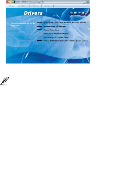
2.3.1Running the support DVD
To begin using the support DVD, place the DVD in your optical drive. The DVD automatically displays the Drivers menu if Autorun is enabled in your computer.
Click an icon to 
 display support
DVD/motherboard information
Click an item to install
If Autorun is NOT enabled in your computer, browse the contents of the support
DVD to locate the file ASSETUP.EXE from the BIN folder. Double-click the
ASSETUP.EXE to run the DVD.
ASUS InstAll-Installation Wizard for Anti-Virus and Drivers Utility
Launches the ASUS InstAll driver installation wizard.
Norton Internet Security 2009
Installs the Norton Internet Security 2009.
Reaktek Audio Driver
Installs the Realtek audio driver and application.
Intel Chipset Inf Update Program
Installs the Intel® chipset Inf update program.
Intel Graphics Accelerator Driver
Installs the Intel® Graphics accerlerator driver.
Atheros AR8121/AR8113/AR8114 PCI-E Ethernet Controller
Installs the Atheros® AR8121/AR8113/AR8114 PCI-E Ethernet Controller.
ASUS V-series P5G41H |
2-3 |
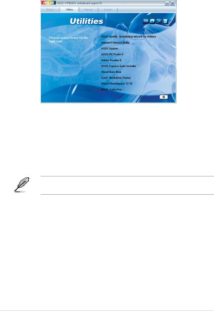
2.3.2Utilities menu
The Utilities menu shows the applications and other software that the motherboard supports.
ASUS InstAll-Installation Wizard for Utilities
Installs all of the utilities through the Installation Wizard.
Atheros Ethernet Utility
Installs the Atheros® Ethernet Utility.
ASUS Update
Allows you to download the latest version of the BIOS from the ASUS website.
Before using the ASUS Update, make sure that you have an Internet connection so you can connect to the ASUS website.
ASUS PC Probe II
This smart utility monitors the fan speed, CPU temperature, and system voltages, and alerts you of any detected problems. This utility helps you keep your computer
in healthy operating condition.
Adobe Acrobat Reader 8
Installs the Adobe® Acrobat® Reader that allows you to open, view, and print documents in Portable Document Format (PDF).
ASUS Express Gate Installer
Installs the ASUS Express Gate application.
2-4 |
Chapter 2: Starting up |

Ulead Burn. Now
Installs the Ulead Burn. Now application for Audio DVD,CD and data disc creation.
Corel MediaOne Starter
Installs the Corel MediaOne Starter application to easily manage, edit share and protect your multimedia data.
Ulead Photolmpact 12 SE
Installs the Photolmpact image editing software.
ASUS Turbo Key
Installs ASUS Turbo Key.
Click |
to display the next screen. |
|
|
WinZip 11
Installs the Winzip utility for easy file-compression and protection.
Microsoft DirectX 9.0c
Installs the Microsoft® DirectX 9.0c driver. The Microsoft DirectX® 9.0c is a multimedia technology that enhances computer graphics and sound. DirectX® improves the multimedia features of you computer so you can enjoy watching TV and movies, capturing videos, or playing games in your computer. Visit the Microsoft website (www.microsoft.com) for updates.
FarStone Utility
Installs the FarStone Utility.
ASUS V-series P5G41H |
2-5 |
Loading...