


V-Series P5V900
ASUS PC (Desktop Barebone)
E3071

First
 Edition

December 2006
Copyright © 2006 ASUSTeK COMPUTER INC.

 All
All
 Rights Reserved.
No part of this manual, including the products and software described in it, may be reproduced, transmitted, transcribed, stored in a retrieval system, or translated into any language in any form or by any means, except documentation kept by the purchaser for backup purposes, without the express written permission of ASUSTeK COMPUTER INC. (“ASUS”).
Product warranty or service will not be extended if: (1) the product is repaired, modified or altered, unless such repair, modification of alteration is authorized in writing by ASUS; or (2) the serial number of the product is defaced or missing.
ASUS PROVIDES THIS MANUAL “AS IS” WITHOUT WARRANTY OF ANY KIND, EITHER EXPRESS OR IMPLIED, INCLUDING BUT NOT LIMITED TO THE IMPLIED WARRANTIES OR CONDITIONS OF MERCHANTABILITY OR FITNESS FOR A PARTICULAR PURPOSE. IN NO EVENT SHALL ASUS, ITS DIRECTORS, OFFICERS, EMPLOYEES OR AGENTS BE LIABLE FOR ANY INDIRECT, SPECIAL,
INCIDENTAL, OR CONSEQUENTIAL DAMAGES (INCLUDING DAMAGES FOR LOSS OF PROFITS, LOSS OF BUSINESS, LOSS OF USE OR DATA, INTERRUPTION OF BUSINESS AND THE LIKE), EVEN IF ASUS HAS BEEN ADVISED OF THE POSSIBILITY OF SUCH DAMAGES ARISING FROM ANY DEFECT OR ERROR IN THIS MANUAL OR PRODUCT.
SPECIFICATIONS AND INFORMATION CONTAINED IN THIS MANUAL ARE FURNISHED FOR INFORMATIONAL USE ONLY, AND ARE SUBJECT TO CHANGE AT ANY TIME WITHOUT NOTICE, AND SHOULD NOT BE CONSTRUED AS A COMMITMENT BY ASUS. ASUS ASSUMES NO RESPONSIBILITY OR LIABILITY FOR ANY ERRORS OR INACCURACIES THAT MAY APPEAR IN THIS MANUAL, INCLUDING THE PRODUCTS AND SOFTWARE DESCRIBED IN IT.
Products and corporate names appearing in this manual may or may not be registered trademarks or copyrights of their respective companies, and are used only for identification or explanation and to the owners’ benefit, without intent to infringe.
ii


Table of contents
Notices................................................................................................. |
vi |
Safety information............................................................................... |
vii |
About this guide................................................................................. |
viii |
System package contents.................................................................... |
x |
Chapter 1: System Introduction |
|
|
1.1 |
Welcome!............................................................................... |
1-2 |
1.2 |
Front panel (external)........................................................... |
1-2 |
1.3 |
Rear panel.............................................................................. |
1-4 |
1.4 |
Internal components.............................................................. |
1-7 |
Chapter 2: |
Basic Installation |
|
|
2.1 |
Preparation............................................................................ |
2-2 |
|
2.2 |
Before you proceed............................................................... |
2-2 |
|
2.3 |
Removing the side cover and front panel assembly.............. |
2-3 |
|
2.4 |
Central Processing Unit (CPU)............................................... |
2-4 |
|
|
2.4.1 |
Overview.................................................................. |
2-4 |
|
2.4.2 |
Installing the CPU..................................................... |
2-4 |
|
2.4.3 Installing the CPU fan and heatsink assembly......... |
2-6 |
|
2.5 |
Installing a DIMM.................................................................... |
2-8 |
|
|
2.5.1 |
Memory configurations............................................ |
2-8 |
|
2.5.2 Installing a DDR2 DIMM.......................................... |
2-11 |
|
|
2.5.3 Removing a DDR2 DIMM......................................... |
2-11 |
|
2.6 |
Expansion slots.................................................................... |
2-12 |
|
|
2.6.1 Installing an expansion card................................... |
2-12 |
|
|
2.6.2 Configuring an expansion card............................... |
2-12 |
|
|
2.6.3 PCI Express x1 slot................................................ |
2-14 |
|
|
2.6.4 |
PCI slots................................................................. |
2-14 |
|
2.6.5 PCI Express x16 slot.............................................. |
2-14 |
|
2.7 |
Installing an optical drive..................................................... |
2-15 |
|
2.8 |
Installing a hard disk drive................................................... |
2-17 |
|
2.9 |
Installing a floppy disk drive................................................ |
2-20 |
|
2.10 |
Re-connecting cables.......................................................... |
2-21 |
|
2.11 |
Reinstalling the cover.......................................................... |
2-22 |
|
iii


Table of contents
Chapter 3: |
Starting up |
|
|
3.1 |
Installing an operating system.............................................. |
3-2 |
|
3.2 |
Powering up........................................................................... |
3-2 |
|
3.3 |
Support CD information......................................................... |
3-2 |
|
|
3.3.1 Running the support CD.......................................... |
3-3 |
|
|
3.3.2 |
Utilities menu........................................................... |
3-4 |
|
3.3.3 |
Make disk................................................................. |
3-5 |
|
3.3.4 |
Manual..................................................................... |
3-5 |
|
3.3.5 |
ASUS Contact information....................................... |
3-6 |
3.4 |
Software information............................................................. |
3-7 |
|
Chapter 4: Motherboard Info |
|
|
4.1 |
Introduction........................................................................... |
4-2 |
4.2 |
Motherboard layout............................................................... |
4-2 |
4.3 |
Jumpers................................................................................. |
4-3 |
4.4 |
Connectors............................................................................ |
4-6 |
Chapter 5: |
BIOS Information |
|
5.1 Managing and updating your BIOS......................................... |
5-2 |
|
5.1.1 |
ASUS Update utility................................................. |
5-2 |
5.1.2 Creating a bootable floppy disk............................... |
5-5 |
|
5.1.3 ASUS EZ Flash 2 utility............................................ |
5-6 |
|
5.1.4 |
AwardBIOS Flash utility............................................ |
5-7 |
5.1.5 Saving the current BIOS file..................................... |
5-9 |
|
5.1.6 ASUS CrashFree BIOS 2 utility............................... |
5-10 |
|
5.2 BIOS setup program............................................................ |
5-11 |
|
5.2.1 |
BIOS menu screen.................................................. |
5-12 |
5.2.2 |
Menu bar................................................................ |
5-12 |
5.2.3 |
Legend bar............................................................ |
5-13 |
iv


Table of contents
|
5.2.4 |
Menu items............................................................ |
5-13 |
|
5.2.5 |
Sub-menu items..................................................... |
5-13 |
|
5.2.6 |
Configuration fields................................................ |
5-13 |
|
5.2.7 |
Pop-up window...................................................... |
5-14 |
|
5.2.8 |
General help........................................................... |
5-14 |
5.3 |
Main menu........................................................................... |
5-15 |
|
|
5.3.1 |
System Time ........................................................ |
5-15 |
|
5.3.2 |
System Date ......................................................... |
5-15 |
|
5.3.3 |
Primary IDE Master/Slave...................................... |
5-16 |
|
5.3.4 |
SATA 1/2.............................................................. |
5-18 |
|
5.3.5 |
HDD SMART Monitoring......................................... |
5-19 |
|
5.3.6 |
Installed Memory................................................... |
5-19 |
|
5.3.7 |
Usable Memory...................................................... |
5-19 |
5.4 |
Advanced menu................................................................... |
5-19 |
|
|
5.4.1 |
CPU Configuration.................................................. |
5-20 |
|
5.4.2 |
Chipset.................................................................. |
5-21 |
|
5.4.3 |
PCIPnP.................................................................... |
5-22 |
|
5.4.4 |
Onboard Device Configuration............................... |
5-23 |
|
5.4.5 |
USB Configuration.................................................. |
5-24 |
5.5 |
Power menu......................................................................... |
5-25 |
|
|
5.5.1 |
ACPI Suspend Type................................................ |
5-25 |
|
5.5.2 |
ACPI APIC Support................................................. |
5-25 |
|
5.5.3 |
APM Configuration................................................. |
5-26 |
|
5.5.4 |
Hardware Monitor.................................................. |
5-28 |
5.6 |
Boot menu........................................................................... |
5-30 |
|
|
5.6.1 |
Boot Device Priority............................................... |
5-30 |
|
5.6.2 |
Boot Settings Configuration.................................. |
5-31 |
|
5.6.3 |
Security................................................................. |
5-32 |
5.7 |
Tool menu........................................................................... |
5-33 |
|
5.8 |
Exit menu............................................................................ |
5-33 |
|
Notices
Federal

 Communications Commission Statement
This device complies with Part 15 of the FCC Rules. Operation is subject to the following two conditions:
•This device may not cause harmful interference, and
•This device must accept any interference received including interference that may cause undesired operation.
This equipment has been tested and found to comply with the limits for a Class B digital device, pursuant to Part 15 of the FCC Rules. These limits are designed to provide reasonable protection against harmful interference in a residential installation. This equipment generates, uses and can radiate radio frequency energy and, if not installed and used in accordance with manufacturer’s instructions, may cause harmful interference to radio communications. However, there is no guarantee that interference will
not occur in a particular installation. If this equipment does cause harmful interference to radio or television reception, which can be determined by turning the equipment off and on, the user is encouraged to try to correct the interference by one or more of the following measures:
•Reorient or relocate the receiving antenna.
•Increase the separation between the equipment and receiver.
•Connect the equipment to an outlet on a circuit different from that to which the receiver is connected.
•Consult the dealer or an experienced radio/TV technician for help.
WARNING! The use of shielded cables for connection of the monitor to the graphics card is required to assure compliance with FCC regulations.
Changes or modifications to this unit not expressly approved by the party responsible for compliance could void the user’s authority to operate this equipment.
Canadian Department of Communications Statement
This digital apparatus does not exceed the Class B limits for radio noise emissions from digital apparatus set out in the Radio Interference Regulations of the Canadian Department of Communications.
This class B digital apparatus complies with Canadian ICES
 -003.
-003.
vi

Safety information
Electrical

 safety
•To prevent electrical shock hazard, disconnect the power cable from the electrical outlet before relocating the system.
•When adding or removing devices to or from the system, ensure that the power cables for the devices are unplugged before the signal cables are connected.
•If the power supply is broken, do not try to fix it by yourself. Contact a qualified service technician or your retailer.
Operation safety
•Before installing devices into the system, carefully read all the documentation that came with the package.
•Before using the product, make sure all cables are correctly connected and the power cables are not damaged. If you detect any damage, contact your dealer immediately.
•To avoid short circuits, keep paper clips, screws, and staples away from connectors, slots, sockets and circuitry.
•Avoid dust, humidity, and temperature extremes. Do not place the product in any area where it may become wet. Place the product on a stable surface.
•If you encounter technical problems with the product, contact a qualified service technician or your retailer.
Lithium-Ion Battery Warning
CAUTION: Danger of explosion if battery is incorrectly replaced. Replace only with the same or equivalent type recommended by the manufacturer. Dispose of used batteries according to the manufacturer’s instructions.
VORSICHT: Explosionsgetahr bei unsachgemäßen Austausch der
Batterie. Ersatz nur durch denselben oder einem vom Hersteller empfohlenem ähnljchen Typ. Entsorgung gebrauchter Batterien nach Angaben des Herstellers.
LASER PRODUCT WARNING |
CLASS 1 LASER PRODUCT |
vii

About this guide
Audience
This guide provides general information and installation instructions about the ASUS V-Series P5V900 barebone system. This guide is intended for experienced users and integrators with hardware knowledge of personal computers.
How this guide is
 organized
This guide contains the following parts:
1. Chapter 1: System introduction
This chapter gives a general description of the ASUS
V-Series P5V900. The chapter lists the system features, including introduction on the front and rear panel, and internal components.
2. Chapter 2: Basic installation
This chapter provides step-by-step instructions on how to install components in the system.
3. Chapter 3: Starting up
This chapter helps you power up the system and install drivers and utilities from the support CD.
4. Chapter 4: Motherboard information
This chapter gives information about the motherboard that comes with the system. This chapter includes the motherboard layout, jumper settings, and connector locations.
5. Chapter 5: BIOS information
This chapter tells how to change system settings through the BIOS Setup menus and describes the BIOS parameters.
viii

Conventions used in this guide
WARNING: Information to prevent injury to yourself when trying to complete a task.
CAUTION: Information to prevent damage to the components when trying to complete a task.
IMPORTANT: Instructions that you MUST follow to complete a task.
NOTE: Tips and additional information to aid in completing a task.
Where to find more information
Refer to the following sources for additional information and for product and software updates.
1. ASUS Websites
The ASUS websites worldwide provide updated information on ASUS hardware and software products. Refer to the ASUS contact information.
2. Optional Documentation
Your product package may include optional documentation, such as warranty flyers, that may have been added by your dealer. These documents are not part of the standard package.
ix

System package contents
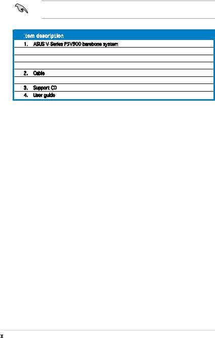
Check your V-Series P5V900 system package for the following items.
If any of the items is damaged or missing, contact your retailer immediately.
Item
 description
1.ASUS V-Series P5V900 barebone system with
•ASUS motherboard
•300 W (peak) PFC power supply unit
•ASUS chassis
2.Cable
•AC power cable
3.Support CD
4.User guide
Chapter 1
This chapter gives a general description of the ASUS V-Series P5V900. The chapter
lists the system features including introduction on the front and rear panel, and internal components.
System introduction
1.1Welcome!
Thank you for choosing the ASUS V-Series P5V900!
The ASUS V-Series P5V900 is an all-in-one barebone system with a versatile home entertainment feature.
The system comes in a stylish casing and powered by the ASUS motherboard that supports the Intel® CoreTM 2 Duo, Intel® Pentium® D, Intel® Pentium® 4 or Intel® Celeron® processor in the 775-land package. This motherboard supports CPUs with the latest Intel CPU technology including Dual-core, EIST and HyperThreading.
The system supports up to 4 GB of system memory using DDR2-667/533/400 DIMMs. High-resolution graphics via integrated graphics controller or PCI Express x16 slot, Serial ATA, USB 2.0, and 6-channel audio feature the system and take you ahead in the world of power computing.
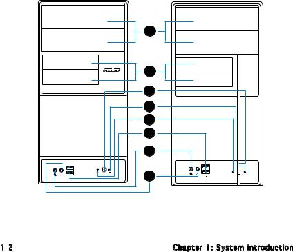
1.2Front panel
The front panel includes the optical drive bays, floppy disk drive slot, power button, and several I/O ports are located at the front panel.
1 |
2 |
3 |
4 |
5 |
6 |
7 |
8 |
1- |
Chapter 1: System introduction |
1.Two empty 5.25-inch bays. These bays are for IDE optical drives.
2.3.5-inch drive bays. These slots are for 3.5-inch floppy or hard disk drives.
3.Power button. Press this button to turn the system on.
4.Reset button. Press this button to reboot the system without turning off the power.
5.HDD
 LED.
LED.

 This LED lights up when data is read from or written to the hard disk drive.
6.USB 2.0 ports. These Universal Serial Bus 2.0 (USB 2.0) ports are available for connecting USB 2.0 devices such as a mouse, printer, scanner, camera, PDA, and others.
7.Headphone
 port. This Line In (green) port connects a headphone with a stereo mini-plug.
8.Microphone port. This Mic (pink) port connects a microphone.
ASUS V-Series P5V900 |
1- |

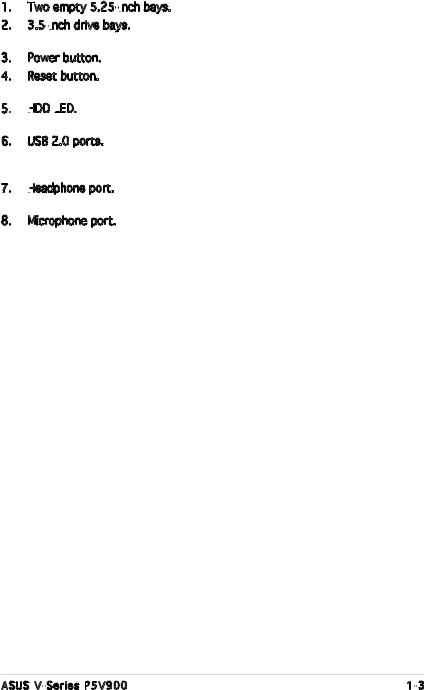
1.3Rear panel
The system rear panel includes the power connector and several I/O ports that allow convenient connection of devices.
1 |
|
2 |
12 |
|
3
4
6
7 |
13 |
|
8
14
9
10
11
15
1.Power connector. This connector is for the power cable and plug.
2.Voltage selector. This switch allows you to adjust the system input voltage according to the voltage supply in your area. See the section “Voltage selector” on page 1-6 before adjusting this switch.
3.PS/2 mouse port. This green 6-pin connector is for a PS/2 mouse.
4.PS/2 keyboard port. This purple 6-pin connector is for a PS/2 keyboard.
1- |
Chapter 1: System introduction |
6.Parallel
 port. This 25-pin port connects a printer, scanner, or other devices.
7.VGA port. This port connects a VGA monitor.
8.USB 2.0 ports 1, 2, 3 and 4. These 4-pin Universal Serial Bus (USB) ports are available for connecting USB 2.0 devices.
9.Microphone port (pink). This port connects a microphone.
10.Line
 Out port (lime). This port connects a headphone or a speaker.
In 4-channel and 6-channel configuration, the function of this port becomes Front Speaker Out.
11.Line
 In
In
 port (light blue). This port connects the tape, CD, DVD player, or other audio sources.
12.Power supply unit fan vent. This vent is for the PSU fan that provides ventilation inside the power supply unit.
13.Chassis fan vent. This vent is for the fan that provides ventilation inside the system chassis.
14.LAN
 (RJ-45) port. This port allows Gigabit connection to a Local Area Network (LAN) through a network hub.
15.Expansion
 slot covers. Remove these covers when installing expansion cards.
Refer to the audio configuration table below for the function of the audio ports in 2, 4, or 6-channel configuration.
Audio 2, 4, or 6-channel
 configuration
Port |
Headset |
4-speaker |
6-speaker |
|
2-speaker |
|
|
|
|
|
|
Light Blue |
Line In |
Surround Out |
Surround Out |
Lime |
Line Out |
Front Speaker Out |
Front Speaker Out |
Pink |
Mic In |
Mic In |
Center/Bass |
ASUS V-Series P5V900 |
1- |
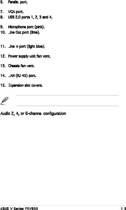
Voltage selector
The PSU has a 115 V/230 V voltage selector switch located beside the power connector. Use this switch to select the appropriate system input voltage according to the voltage supply in your area.
If the voltage supply in your area is 100 127 V, set this switch to 115 V. If the voltage supply in your area is 200 240 V, set this switch to 230 V.
115V/230V Voltage selector
Setting the switch to 115V in a 230V environment or 230V in a 115V environment will seriously damage the system!
1- |
Chapter 1: System introduction |
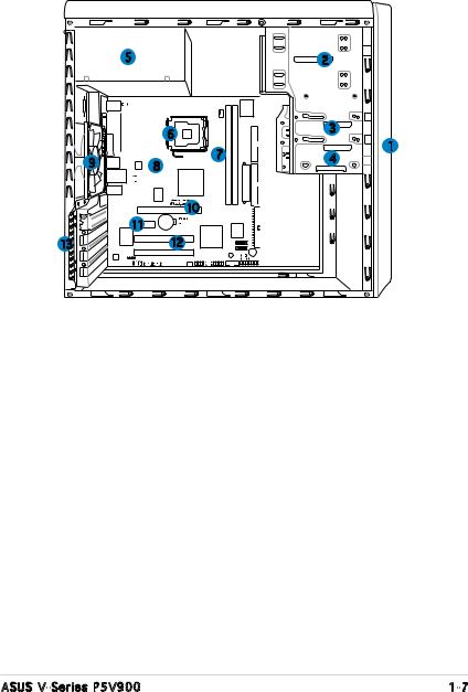
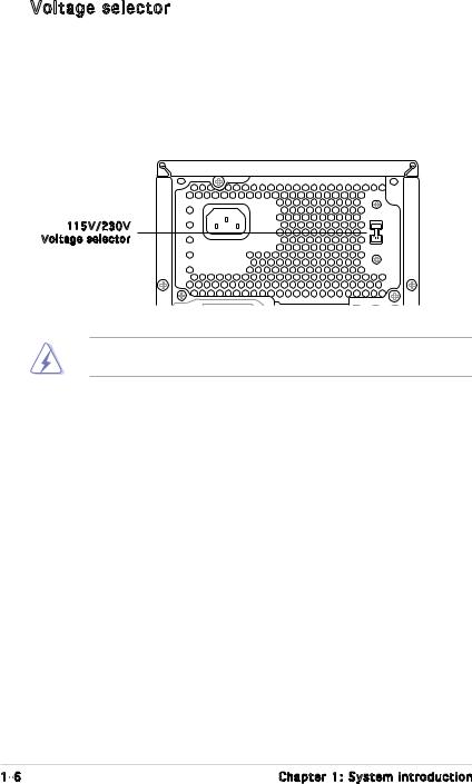
1.4Internal components
The illustration below is the internal view of the system when you remove the top cover and the power supply unit. The installed components are labeled for your reference. Proceed to Chapter 2 for instructions on installing additional system components.
|
5 |
|
|
2 |
|
|
6 |
|
3 |
|
|
|
1 |
|
|
|
|
7 |
|
9 |
8 |
|
4 |
|
|
|
|||
|
|
|
10 |
|
|
11 |
|
|
|
13 |
|
12 |
|
|
|
|
|
|
|
|
|
|
|
|
|
1. |
Front panel cover |
8. |
ASUS motherboard |
|||||||
2. |
5.25-inch optical drive bays |
9. |
Chassis fan |
|||||||
3. |
Hard disk drive bay |
10. |
PCI Express x16 slot |
|||||||
4. |
Floppy disk drive bay |
11. |
PCI Express x1 slot |
|||||||
5. |
Power supply unit |
12. |
PCI slots |
|||||||
6. |
CPU socket |
13. |
Metal bracket lock |
|||||||
7.DIMM sockets
ASUS V-Series P5V900 |
1- |
1- |
Chapter 1: System introduction |

Chapter 2
This chapter provides step-by-step instructions on how to install components in the system.
Basic installation
2.1Preparation
Before you proceed, make sure that you have all the components you plan to install in the system.
Basic components to install

1.Central Processing Unit (CPU)
2.DDR2 Dual Inline Memory Module (DIMM)
3.Expansion card(s)
4.Hard disk drive
5.Optical drive
6.Floppy disk drive
Tool
Phillips (cross) screw driver
2.2Before you proceed
Take note of the following precautions before you install components into the system.
•Use a grounded wrist strap or touch a safely grounded object or
a metal object, such as the power supply case, before handling components to avoid damaging them due to static electricity.
•Hold components by the edges to avoid touching the ICs on them.
•Whenever you uninstall any component, place it on a grounded antistatic pad or in the bag that came with the component.
The motherboard comes with an onboard standby power LED. This LED lights up to indicate that the system is ON, in sleep mode or in soft-off mode, and not powered OFF. Unplug the power cable from the power outlet and make sure that the standby power LED is OFF before installing any system component.
2- |
Chapter 2: Basic installation |
2.3Removing the side cover and front panel assembly
1.Remove the cover screws on the rear panel.
2.Pull the side cover toward the rear panel until its hooks disengage from the chassis tab holes. Set the side cover aside.
3.Locate the front panel assembly hooks, then lift them until they disengage from the chassis.
4.Swing the front panel assembly to the right, until the hinge-like tabs on the right side of the assembly are exposed.
5.Remove the front panel assembly, then set aside.
|
3 |
4 |
1 |
|
|
Air duct |
|
|
2 |
3 |
4 |
|
|
1 |
4 |
|
3
2
Chassis tab holes
4
ASUS V-Series P5V900 |
2- |
2.4Central Processing Unit (CPU)
2.4.1 Overview
The motherboard comes with a surface mount LGA775 socket designed for the Intel® Pentium® 4 processor in the 775-land package.
•Your boxed Intel® Pentium® 4 LGA775 processor package should come with installation instructions for the CPU, heatsink, and the retention mechanism. If the instructions in this section do not match the CPU documentation, follow the latter.
•Check your motherboard to make sure that the PnP cap is on the CPU socket and the socket contacts are not bent. Contact your retailer immediately if the PnP cap is missing, or if you see any damage to the PnP cap/socket contacts/motherboard components. ASUS will shoulder the cost of repair only if the damage is shipment/ transit-related.
•Keep the cap after installing the motherboard. ASUS will process
Return Merchandise Authorization (RMA) requests only if the motherboard comes with the cap on the LGA775 socket.
•The product warranty does not cover damage to the socket contacts resulting from incorrect CPU installation/removal, or misplacement/loss/incorrect removal of the PnP cap.
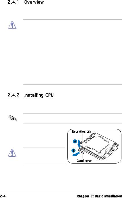
2.4.2 Installing
 CPU
CPU
To install a CPU:
1.Locate the CPU socket on the motherboard.
Before installing the CPU, make sure that the socket box is facing towards you and the load lever is on your left.
2.Press the load lever with your thumb (A), then move it to the left (B) until it is released from the retention tab.
To prevent damage to the socket pins, do not remove the PnP cap unless you are installing a CPU.
Retention tab
A
B
Load
 lever
lever

2- |
Chapter 2: Basic installation |
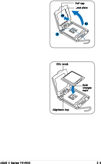
3.Lift the load lever in the direction of the arrow to a 135º angle.
4.Lift the load plate with your thumb and forefinger to a 100º angle (4A), then push the PnP cap from the load plate window to remove (4B).
PnP cap
Load
 plate
plate
4B
4A
3
5.Position the CPU over the socket, making sure that the gold triangle is on the
bottom left corner of the socket then fit the socket alignment key into the CPU notch.
CPU notch
Gold triangle mark
Alignment key
ASUS V-Series P5V900 |
2- |
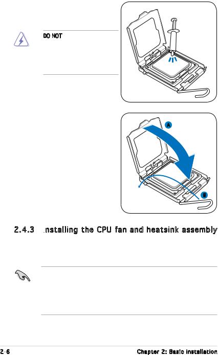
6.Apply Thermal Interface Material on the CPU before closing the
load plate.
DO NOT eat the Thermal Interface Material. If it gets into your eyes or touches your skin, make sure to wash it off immediately, and seek professional medical help.
7.Close the load plate (A), then
push the load lever (B) until it |
A |
snaps into the retention tab. |
|
B
2.4.3 Installing the CPU fan and heatsink assembly
The Intel® Pentium® 4 LGA775 processor requires a specially designed heatsink and fan assembly to ensure optimum thermal condition and performance.
•When you buy a boxed Intel® Pentium® 4 processor, the package
includes the CPU fan and heatsink assembly. If you buy a CPU separately, make sure that you use only Intel® certified multi directional heatsink and fan.
•Your Intel® Pentium® 4 LGA775 heatsink and fan assembly comes in a push-pin design and requires no tool to install.
2- |
Chapter 2: Basic installation |
If you purchased a separate CPU heatsink and fan assembly, make sure that the Thermal Interface Material is properly applied to the CPU heatsink or CPU before you install the heatsink and fan assembly.
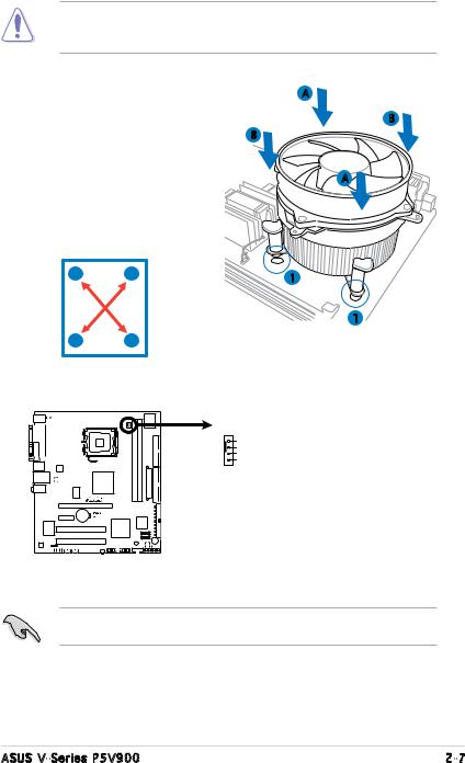
To install the CPU heatsink and fan: |
A |
1. Place the heatsink on top of the |
B |
installed CPU, making sure that |
B |
the four fasteners match the |
|
holes on the motherboard. |
A |
|
2.Push down two fasteners at
a time in a diagonal sequence to secure the heatsink and fan assembly in place.
A |
B |
1 |
|
|
1
BA
3.When the fan and heatsink assembly is in place, connect the CPU fan cable to the connector on the motherboard.
CPU_FAN
GND
CPU FAN PWR
CPU FAN IN
CPU FAN PWM
CPU Fan Connector
Do not forget to connect the CPU fan connector! Hardware monitoring errors can occur if you fail to plug this connector.
ASUS V-Series P5V900 |
2- |
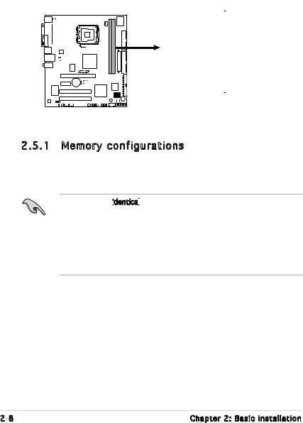
2.5Installing a DIMM
The system motherboard comes with two Double Data Rate 2 (DDR2) Dual Inline Memory Module (DIMM) sockets.
The following figure illustrates the location of the sockets:
DIMM1 |
DIMM2 |
112 Pins 128 Pins
240-pin DDR2 DIMM Sockets
2.5.1 Memory configurations
You may install up to 4 GB system memory using 256 MB, 512 MB, 1 GB and 2GB DDR2 DIMMs.
•Install only identical


 (the same type and size) DDR2 memory modules.
•Install only ASUS-certified memory modules. Refer to the DDR2 Qualified Vendors List on the next page for details.
•Always install DIMMs with the same CAS latency. For optimum compatibility, we recommend that you obtain memory modules from the same vendor.
2- |
Chapter 2: Basic installation |
Qualified Vendors Lists
 (QVL)
(QVL)
DDR2-533
|
|
|
|
|
|
DIMM Support |
|
|
|
|
|
|
|
||
|
Size |
Vendor |
Model |
Side(s) |
Component |
A |
B |
|
256MB |
KINGSTON |
E5116AF-5C-E |
SS |
KVR533D2N4/256 |
V |
V |
|
512MB |
KINGSTON |
HYB18T512800AF37 |
SS |
KVR533D2N4/512 |
V |
V |
|
1024MB |
KINGSTON |
5YDIID9GCT |
DS |
KVR533D2N4/1G |
V |
V |
|
256MB |
Qimonda |
HYB18T512160AF-3.7 |
SS |
HYS64T32000HU-3.7-A |
V |
V |
|
512MB |
Qimonda |
HYB18T512800AF37 |
S |
HYS64T64000HU-3.7-A |
V |
V |
|
1024MB |
Qimonda |
HYB18T512800AF37 |
DS |
HYS64T128020HU-3.7-A |
V |
V |
|
2048MB |
Qimonda |
HYB18T1G800AF-3.7 |
DS |
HYS64T256020HU-3.7-A |
V |
V |
|
256MB |
Qimonda |
HYB18T5121608BF-3.7 |
SS |
HYS64T32000HU-3.7-B |
V |
V |
|
512MB |
Qimonda |
HYB18T512800BF37 |
SS |
HYS64T64000HU-3.7-B |
V |
V |
|
1024MB |
Qimonda |
HYB18T512800BF37 |
DS |
HYS64T128020HU-3.7-B |
V |
V |
|
512MB |
Hynix |
HY5PS12821F-C4 |
SS |
HYMP564U648-C4 |
V |
V |
|
1024MB |
Hynix |
HY5PS12821F-C4 |
DS |
HYMP512U648-C4 |
V |
V |
|
1024MB |
Hynix |
HY5PS12821FP-C4 |
DS |
HYMP512U648-C4 |
V |
V |
|
512MB |
Hynix |
HY5PS12821AFP-C3 |
SS |
HYMP564U64AP8-C3 |
V |
V |
|
1024MB |
Hynix |
HY5PS12821AFP-C3 |
DS |
HYMP512U64AP8-C3 |
V |
V |
|
512MB |
ELPIDA |
E5108AB-5C-E |
SS |
EBE51UD8ABFA-5C |
V |
V |
|
512MB |
ELPIDA |
E5108AB-5C-E |
SS |
EBE51UD8ABFA-5C-E |
V |
V |
|
1024MB |
ELPIDA |
E5108AB-5C-E |
DS |
EBE11UD8ABFA-5C-E |
V |
V |
|
256MB |
Apacer |
E5116AB-5C-E |
SS |
78.81077.420 |
V |
V |
|
512MB |
KINGMAX |
E5108AE-5C-E |
SS |
KLBC28F-A8EB4 |
V |
V |
|
1024MB |
KINGMAX |
E5108AE-5C-E |
DS |
KLBD48F-A8EB4 |
V |
V |
|
512MB |
KINGMAX |
KKEA88E4AAK-37 |
SS |
KLBC28F-A8KE4 |
V |
V |
|
1024MB |
KINGMAX |
5MB22D9DCN |
DS |
KLBD48F-A8ME4 |
V |
V |
|
256MB |
CENTURY |
K4T56083QF-GCD5 |
SS |
25V6S8SSD5F4-K43 |
V |
V |
|
512MB |
CENTURY |
E5108AB-5C-E |
SS |
25V2H8EL5CB4-J43 |
V |
V |
|
512MB |
Aeneon |
AET93F370A |
SS |
AET660UD00-370A98Z |
V |
V |
|
512MB |
Aeneon |
AET93F370A |
SS |
AET660UD00-370A98X |
V |
V |
|
1024MB |
Aeneon |
AET93F370A |
DS |
AET760UD00-370A98Z |
V |
V |
|
1024MB |
Aeneon |
AET92F370A |
DS |
AET760UD00-370A98S |
V |
V |
|
1024MB |
PQI |
64MX8D2-E |
DS |
MEAB-323LA |
V |
V |
|
512MB |
PQI |
64MX8D2-E |
SS |
MEAB-423LA |
V |
V |
|
512MB |
TwinMOS |
K4T51083QB-GCD5 |
SS |
8D-22JB5-K2T |
V |
V |
|
256MB |
SimpleTech |
858S032F25A |
SS |
SVM-42DR2/256 |
V |
V |
|
512MB |
SimpleTech |
858S064F25A |
SS |
SVM-42DR2/512 |
V |
V |
|
1024MB |
Patriot |
Heat-Sink Package |
SS |
PDC21G5600+XBLK |
V |
V |
|
256MB |
Patriot |
PM32M16D2B-3.7KC |
SS |
PSD2256533 |
V |
V |
|
512MB |
Patriot |
PM64M8D2B-3.7KC |
SS |
PSD2512533 |
V |
V |
|
1024MB |
Patriot |
PM64M8D2B-3.7KC |
DS |
PSD21G5332 |
V |
V |
|
512MB |
UMAX |
U2S12D30TP-5C |
SS |
53014051-7100 |
V |
V |
|
512MB |
Veritech |
VTD264M8PC6G |
SS |
GTP512HLTM46DG |
V |
V |
|
1024MB |
Veritech |
VTD264M8PC6G |
DS |
GTP01GHLTM56DG |
V |
V |
|
|
|
|
|
|
|
|
ASUS V-Series P5V900 |
2- |
DDR2-667
|
|
|
|
|
DIMM Support |
|
|
|
|
|
|
||
Size |
Vendor |
Model |
Side(s) |
Component |
A |
B |
512MB |
KINGSTON |
E5108AE-6E-E |
SS |
KVR667D2N5/512 |
V |
V |
1024MB |
KINGSTON |
E5108AE-6E-E |
DS |
KVR667D2N5/1G |
V |
V |
512MB |
KINGSTON |
E5108AE-6E-E |
SS |
KVR667D2E5/512 |
V |
V |
256MB |
KINGSTON |
HYB18T256800AF3 |
SS |
KVR667D2N5/256 |
V |
V |
256MB |
Qimonda |
HYB18T512160AF-3S |
SS |
HYS64T32000HU-3S-A |
V |
V |
512MB |
Qimonda |
HYB18T512800AF3S |
SS |
HYS64T64000HU-3S-A |
V |
V |
1024MB |
Qimonda |
HYB18T512800AF3S |
DS |
HYS64T128020HU-3S-A |
V |
V |
256MB |
Qimonda |
HYB18T512160BF-3S |
SS |
HYS64T32000HU-3S-B |
V |
V |
512MB |
Qimonda |
HYB18T512800BF3S |
SS |
HYS64T64000HU-3S-B |
V |
V |
1024MB |
Qimonda |
HYB18T512800BF3S |
DS |
HYS64T128020HU-3S-B |
V |
V |
256MB |
SAMSUNG |
K4T51163QC-ZCE6 |
SS |
M378T3354CZ0-CE6 |
V |
V |
512MB |
SAMSUNG |
ZCE6K4T51083QC |
SS |
M378T6553CZ0-CE6 |
V |
V |
1024MB |
SAMSUNG |
ZCE6K4T51083QC |
DS |
M378T2953CZ0-CE6 |
V |
V |
512MB |
Hynix |
HY5PS12821AFP-Y5 |
SS |
HYMP564U64AP8-Y5 |
V |
V |
1024MB |
Hynix |
HY5PS12821AFP-Y5 |
DS |
HYMP512U64AP8-Y5 |
V |
V |
512MB |
Hynix |
HY5PS12821AFP-Y4 |
SS |
HYMP564U64AP8-Y4 |
V |
V |
1024MB |
Hynix |
HY5PS12821AFP-Y4 |
DS |
HYMP512U64AP8-Y4 |
V |
V |
256MB |
ELPIDA |
E2508AB-6E-E |
SS |
EBE25UC8ABFA-6E-E |
V |
V |
512MB |
ELPIDA |
E5108AE-6E-E |
SS |
EBE51UD8AEFA-6E-E |
V |
V |
512MB |
A-DATA |
AD29608A8B-3EG |
SS |
M20AD5Q3H3163J1C52 |
V |
V |
512MB |
A-DATA |
AD29608A8A-3EG |
SS |
M2OAD5G3H3166I1C52 |
V |
V |
512MB |
crucial |
Heat-Sink Package |
SS |
BL6464AA663.8FD |
V |
V |
1024MB |
crucial |
Heat-Sink Package |
DS |
BL12864AA663.16FD |
V |
V |
1024MB |
crucial |
Heat-Sink Package |
DS |
BL12864AL664.16FD |
V |
V |
1024MB |
Apacer |
E5108AE-6E-E |
DS |
78.01092.420 |
V |
V |
512MB |
Apacer |
AM4B5708GQJS7E |
SS |
AU512E667C5KBGC |
V |
V |
1024MB |
Apacer |
AM4B5708GQJS7E |
DS |
AU01GE667C5KBGC |
V |
V |
512MB |
Kingmax |
KKEA88B4LAUG-29DX |
SS |
KLCC28F-A8KB5 |
V |
V |
1024MB |
Kingmax |
KKEA88B4LAUG-29DX |
DS |
KLCD48F-A8KB5 |
V |
V |
512MB |
Transcend |
E5108AE-6E-E |
SS |
TS64MLQ64V6J |
V |
V |
1024MB |
Transcend |
E5108AE-6E-E |
DS |
TS128MLQ64V6J |
V |
V |
512MB |
Transcend |
J12Q3AB-6 |
SS |
JM367Q643A-6 |
V |
V |
1024MB |
Transcend |
J12Q3AB-6 |
DS |
JM388Q643A-6 |
V |
V |
512MB |
Veritech |
VTD264M8PC5G |
SS |
GTP512HLTM45EG |
V |
V |
1024MB |
Veritech |
VTD264M8PC5G |
DS |
GTP01GHLTM55EG |
V |
V |
512MB |
TwinMOS |
E5108AE-GE-E |
SS |
8G-25JK5-EBT |
V |
V |
1024MB |
NANYA |
NT5TU128M8BJ-3C |
SS |
NT1GT64U88B0JY-3C |
V |
V |
512MB |
GEIL |
Heat-Sink Package |
SS |
GX21GB5300DC |
V |
V |
512MB |
GEIL |
Heat-Sink Package |
SS |
GX21GB5300SDC |
V |
V |
512MB |
Aeneon |
AET93F30DA |
SS |
AET660UD00-30DA98Z |
V |
V |
1024MB |
Aeneon |
AET93F30DA |
DS |
AET760UD00-30DA98Z |
V |
V |
512MB |
Kingbox |
EPD264082200-4KI0629 |
SS |
N/A |
V |
V |
1024MB |
Kingbox |
EPD264082200-4KI0629 |
DS |
N/A |
V |
V |
Side(s): SS - Single-sided DS - Double-sided
CL: CAS Latency
DIMM support:
A- Supports one module inserted into either slot, in Single-channel memory configuration.
B- Supports one pair of modules inserted into both slots as one pair of Dual-channel memory configuration.
2-10 |
Chapter 2: Basic installation |
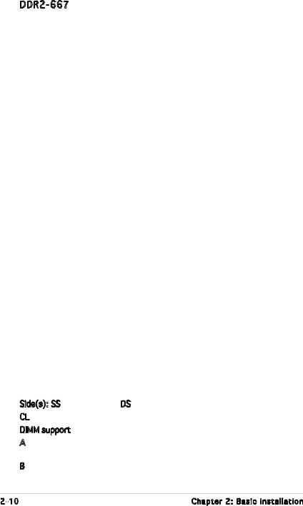
2.5.2 Installing a DDR2 DIMM
Make sure to unplug the power supply before adding or removing DIMMs or other system components. Failure to do so may cause severe damage to both the motherboard and the components.
1.Unlock a DDR2 DIMM socket by pressing the retaining clips outward.
2.Align a DIMM on the socket such that the notch on the
DIMM matches the break on |
|
the socket. |
1 |
2
DDR2 DIMM notch
1
Unlocked retaining clip
A DDR2 DIMM is keyed with a notch so that it fits in only one direction.
DO NOT force a DIMM into a socket to avoid damaging the DIMM.
3. Firmly insert the DIMM into the |
|
3 |
socket until the retaining clips |
|
|
snap back in place and the DIMM |
|
|
is properly seated. |
|
|
Locked Retaining Clip |
||
2.5.3 Removing a DDR2 DIMM |
|
|
Follow these steps to remove a DIMM. |
|
2 |
1. Simultaneously press the |
|
1 |
|
|
|
retaining clips outward to |
|
|
unlock the DIMM. |
1 |
|
|
DDR2 DIMM notch |
|
|
|
|
Support the DIMM lightly with your fingers when pressing the retaining clips. The DIMM might get damaged when it flips out with extra force.
2.Remove the DIMM from the socket.
ASUS V-Series P5V900 |
2-11 |
2.6Expansion slots
In the future, you may need to install expansion cards. The following sub sections describe the slots and the expansion cards that they support.
Make sure to unplug the power cord before adding or removing expansion cards. Failure to do so may cause you physical injury and damage motherboard components.
2.6.1 Installing an expansion card
To install an expansion card:
1.Before installing the expansion card, read the documentation that came with it and make the necessary hardware settings for the card.
2.Remove the system unit cover (if your motherboard is already installed in a chassis).
3.Remove the bracket opposite the slot that you intend to use. Keep the screw for later use.
4.Align the card connector with the slot and press firmly until the card is completely seated on the slot.
5.Secure the card to the chassis with the screw you removed earlier.
6.Replace the system cover.
2.6.2 Configuring an expansion card
After installing the expansion card, configure it by adjusting the software settings.
1.Turn on the system and change the necessary BIOS settings, if any. See Chapter 5 for information on BIOS setup.
2.Assign an IRQ to the card. Refer to the tables on the next page.
3.Install the software drivers for the expansion card.
2-12 |
Chapter 2: Basic installation |
 Loading...