


disassembly procedure
3Chapter
Disassembly Procedure
Please follow the information provided in this section to perform the complete disassembly procedure of the notebook. Be sure to use proper tools described before.
ASUS V6000 Series Notebook consists of various modules. This chapter describes the procedures for the complete notebook disassembly. In addition, in between procedures, the detailed disassembly procedure of individual modules will be provided for your service needs.
The disassembly procedure consists of the following steps:
•Battery Module
•HDD Module
•Memory Module
•CPU Module
•Mini PCI Module
•Optical Drive Module
•Keyboard Module
•Microphone Module
•Top Case Module
•Speaker Module
•LCD Module
•Motherboard Module
3 - 1 |
V6 |
B A T T E R Y M O D U L E
H D D
M O D U L E
H D D
R E M O V A L
disassembly procedure
Battery Module
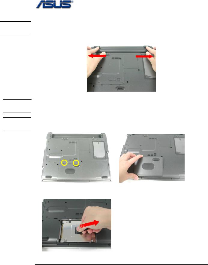
The illustration below shows how to remove the battery module.
1. Press latch to open the battery module, then lift battery module away from the system.
HDD Module
The illustrations below show how to remove the HDD module from the notebook.
Removing HDD Module
1.Remove 1 screw (M2*5L(K)), then remove the HDD door.
M2*5L
2.Pull and lift the hard disk module and take away the hard disk module.
3 - 2 |
V6 |

M E M O R Y M O D U L E
M E M O R Y R E M O V A L
disassembly procedure
Memory Module
The V6000 Series Notebook does not have onboard RAM. There are two SO-DIMM sockets for installing SO-DIMM RAM. It can upgrade the total memory size up to 1GB with a 512MB module on each socket.
Removing Memory module
1. Remove 6 screws (M2*5L(K)), then remove the CPU / DIMM door.
M2*5L
2. Pop the module up to a 45° angles, and then pulling out the module in that angle.
Don’t touch it!
Notice Don’t touch the dies on the Memory.
3 - 3 |
V6 |

C P U M O D U L E
R E M O V A L
C P U
R E M O V A L
disassembly procedure
CPU Module
The illustrations below show how to remove the CPU module from the notebook.
Removing CPU Module
1.Remove 2 screws(M2*5L(K)) and disconnect the FAN connector and then take away the Fan Module.
M2*5L
2.Remove the 4 screws (M2*5L(K)) by order upon the thermal module and take away the CPU heat sink module gently
3 2
M2*5L
1 4
3 - 4 |
V6 |
M I N I P C I M O D U L E
M I N I P C I R E M O V A L
disassembly procedure
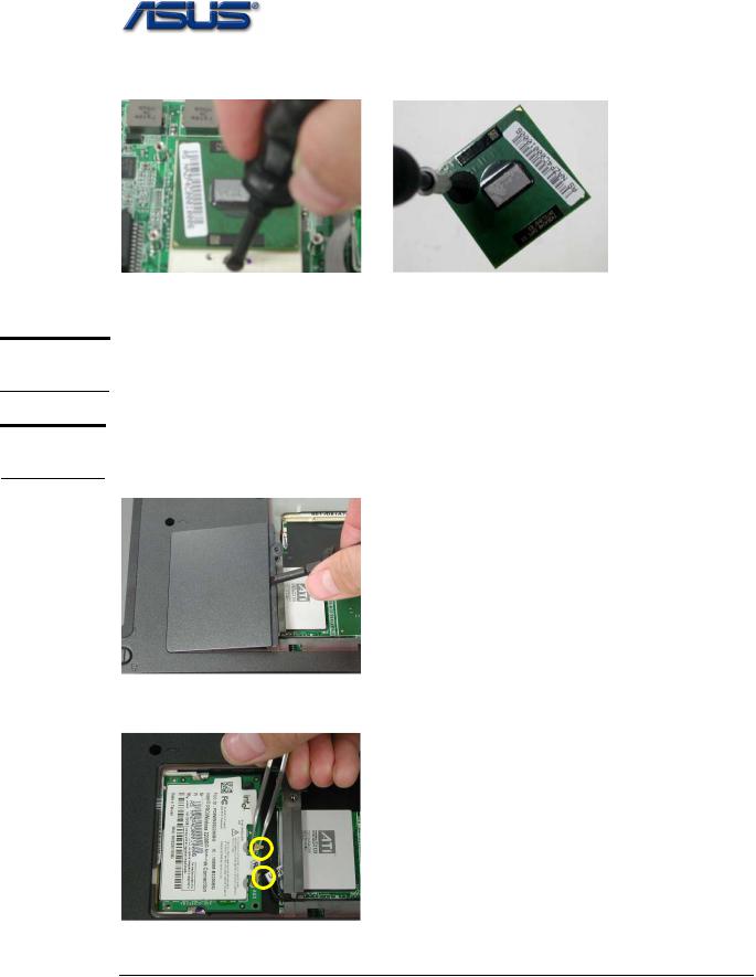
3.Turn the non-removable screw here 180 degrees counter-clockwise to loosen the CPU and take the CPU away
Note: If thermal module has no thermal pad on it, please plus a thermal pad on the CPU die before assembling.
MINI PCI Module
This socket usually has Wireless LAN module when leaving the factory, this socket is for optional system upgrade.
Removing MINI PCI Module
1.Use Molex CPU Socket to remove Wireless LAN door, then take the mini-PCI cover off.
2. Remove 2 Antenna cables from wireless LAN module
|
|
|
V6 |
|
|
|
|
3 - 5 |
|||
O P T I C A L
D R I V E
R E M O V A L
disassembly procedure
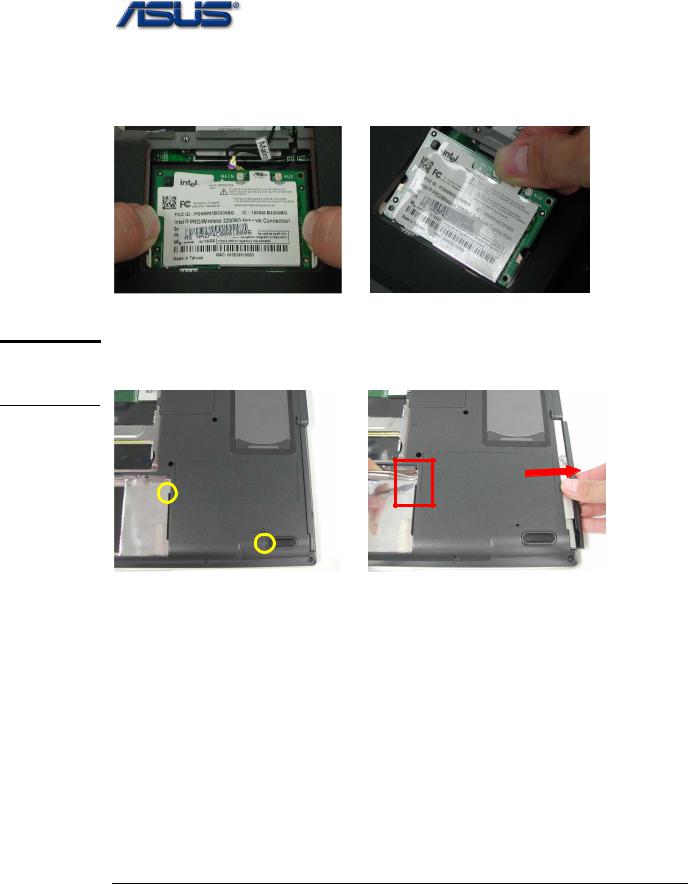
3. Remove the wireless LAN module by opening the 2 latches aside, which will pop the module up to an angle of 30°, then pull out the module in that angle just like memory module.
Optical Drive Module
Remove 2 screws(M2*5L(K)) and use tweezers to put the Optical Drive Module out.
M2*5L
3 - 6 |
V6 |
 Loading...