


V7-P5G43M
V7-series P5G43M
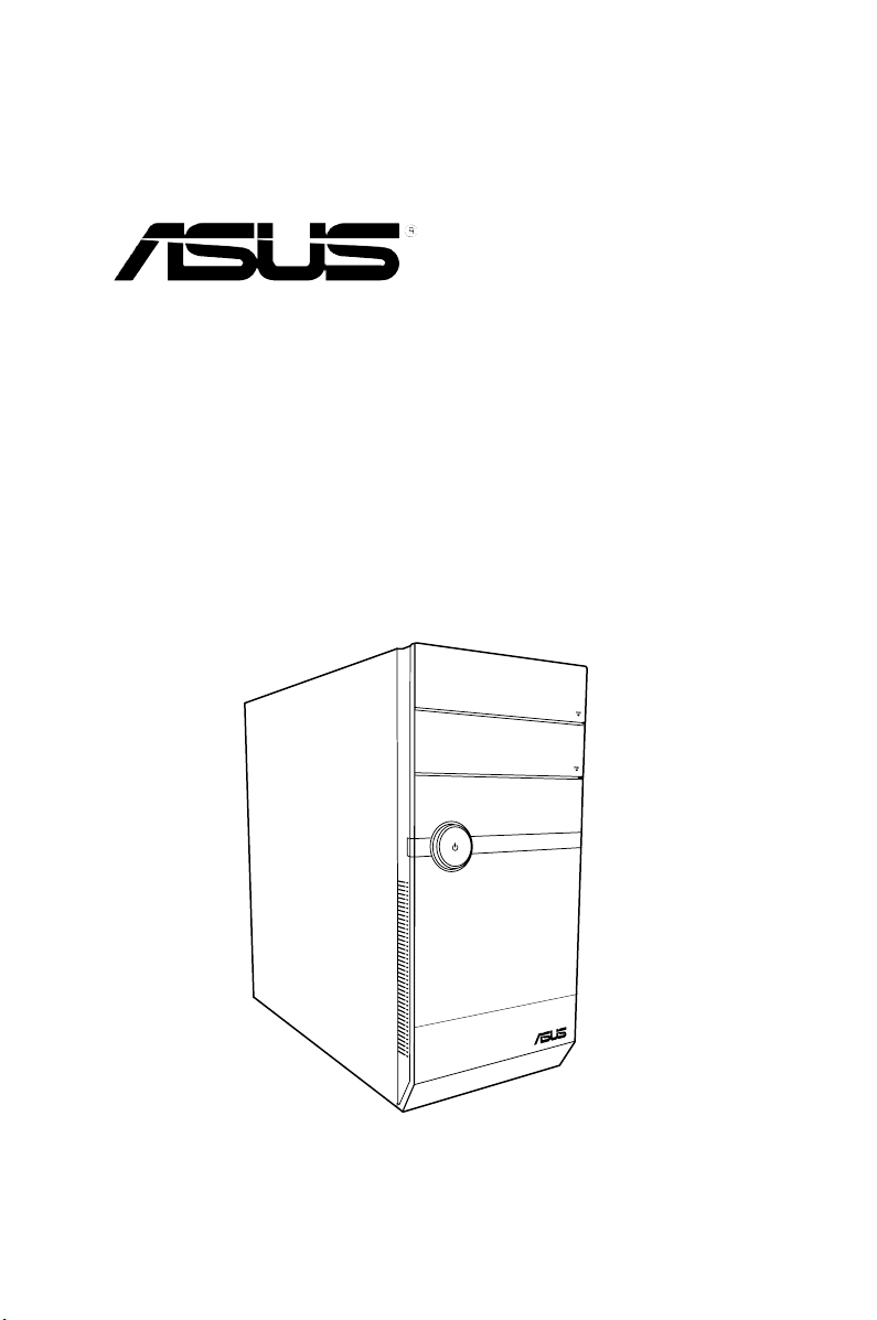
ASUS PC (Desktop Barebone)
User’s Manual

ii
Copyright © 2009 ASUSTeK Computer Inc. All Rights Reserved.
No part of this manual, including the products and software described in it, may be reproduced,
transmitted, transcribed, stored in a retrieval system, or translated into any language in any form or by any
means, except documentation kept by the purchaser for backup purposes, without the express written
permission of ASUSTeK Computer Inc. (“ASUS”).
Product warranty or service will not be extended if: (1) the product is repaired, modied or altered, unless
such repair, modication of alteration is authorized in writing by ASUS; or (2) the serial number of the
product is defaced or missing.
ASUS PROVIDES THIS MANUAL “AS IS” WITHOUT WARRANTY OF ANY KIND, EITHER EXPRESS
OR IMPLIED, INCLUDING BUT NOT LIMITED TO THE IMPLIED WARRANTIES OR CONDITIONS OF
MERCHANTABILITY OR FITNESS FOR A PARTICULAR PURPOSE. IN NO EVENT SHALL ASUS, ITS
DIRECTORS, OFFICERS, EMPLOYEES OR AGENTS BE LIABLE FOR ANY INDIRECT, SPECIAL,
INCIDENTAL, OR CONSEQUENTIAL DAMAGES (INCLUDING DAMAGES FOR LOSS OF PROFITS,
LOSS OF BUSINESS, LOSS OF USE OR DATA, INTERRUPTION OF BUSINESS AND THE LIKE),
EVEN IF ASUS HAS BEEN ADVISED OF THE POSSIBILITY OF SUCH DAMAGES ARISING FROM ANY
DEFECT OR ERROR IN THIS MANUAL OR PRODUCT.
SPECIFICATIONS AND INFORMATION CONTAINED IN THIS MANUAL ARE FURNISHED FOR
INFORMATIONAL USE ONLY, AND ARE SUBJECT TO CHANGE AT ANY TIME WITHOUT NOTICE,
AND SHOULD NOT BE CONSTRUED AS A COMMITMENT BY ASUS. ASUS ASSUMES NO
RESPONSIBILITY OR LIABILITY FOR ANY ERRORS OR INACCURACIES THAT MAY APPEAR IN THIS
MANUAL, INCLUDING THE PRODUCTS AND SOFTWARE DESCRIBED IN IT.
Products and corporate names appearing in this manual may or may not be registered trademarks or
copyrights of their respective companies, and are used only for identication or explanation and to the
owners’ benet, without intent to infringe.
E4966
First Edition V1
August 2009

iii
Table of contents
Notices ......................................................................................................... vi
Safety information
..................................................................................... vii
About this guide
....................................................................................... viii
System package contents
........................................................................... x
Chapter 1 System introduction
1.1 Welcome! ...................................................................................... 1-2
1.2 Front panel
................................................................................... 1-2
1.2.1 V7-P5G43M front panel ..................................................
1-2
1.3 Rear panel
..................................................................................... 1-4
Voltage selector .............................................................................. 1-6
1.4 Internal components
.................................................................... 1-7
1.5 QualiedVendorsLists(QVL)
.................................................... 1-8
Chapter 2 Starting up
2.1 Installing an operating system ................................................... 2-2
2.2 Powering up
.................................................................................. 2-2
2.3 SupportDVDinformation
............................................................ 2-2
2.3.1 Running the support DVD ...............................................
2-3
2.3.2 Utilities menu ..................................................................
2-4
2.3.3 ASUS Contact information ..............................................
2-5
2.3.4 Other information ............................................................
2-6
2.4 Software information
................................................................... 2-8
2.4.1 ASUS AI Manager ...........................................................
2-8
2.4.2 ASUS Express Gate .....................................................
2-14
Chapter 3 Motherboard info
3.1 Introduction .................................................................................. 3-2
3.2 Motherboard layout
...................................................................... 3-2
3.3 Jumpers
........................................................................................ 3-3
3.4 Connectors
................................................................................... 3-5
Chapter 4 BIOS setup
4.1 Managing and updating your BIOS ............................................ 4-2
4.1.1 ASUS Update utility ........................................................
4-2
4.1.2 ASUS EZ Flash 2 utility ...................................................
4-3

iv
Table of contents
4.1.3 ASUS CrashFree BIOS .................................................. 4-4
4.2 BIOS setup program
.................................................................... 4-5
4.2.1 BIOS menu screen ..........................................................
4-6
4.2.2 Menu bar .........................................................................
4-6
4.2.3 Navigation keys ...............................................................
4-7
4.2.4 Menu items .....................................................................
4-7
4.2.5 Submenu items ...............................................................
4-7
4.2.6 Conguration elds .........................................................
4-7
4.2.7 Pop-up window ...............................................................
4-7
4.2.8 Scroll bar .........................................................................
4-7
4.2.9 General help ...................................................................
4-7
4.3 Main menu
.................................................................................... 4-8
4.3.1 System Time ..................................................................
4-8
4.3.2 System Date ...................................................................
4-8
4.3.3
SATA 1-6 ............................................................................................4-8
4.3.4 Storage Conguration .....................................................
4-9
4.3.5 System Information .......................................................
4-10
4.4 Advanced menu
......................................................................... 4-11
4.4.1 CPU Conguration .........................................................
4-11
4.4.2 Chipset ..........................................................................
4-12
4.4.3 Onboard Devices Conguration ....................................
4-13
4.4.4 USB Conguration ........................................................
4-14
4.4.5 PCI PnP ........................................................................
4-15
4.5 Power menu
................................................................................ 4-16
4.5.1 Suspend Mode ..............................................................
4-16
4.5.2 ACPI 2.0 Support ..........................................................
4-16
4.5.3 ACPI APIC Support .......................................................
4-16
4.5.4 APM Conguration ........................................................
4-17
4.5.5 Hardware Monitor .........................................................
4-17
4.6 Boot menu
.................................................................................. 4-19
4.6.1 Boot Device Priority ......................................................
4-19
4.6.2 Boot Settings Conguration ..........................................
4-19
4.6.3 Security .........................................................................
4-20
4.7 Tools menu
................................................................................. 4-22

v
Table of contents
4.7.1 ASUS EZ Flash 2 .......................................................... 4-22
4.7.2 AI NET 2
........................................................................ 4-22
4.8 Exit menu
.................................................................................... 4-23

vi
Notices
Federal Communications Commission Statement
This device complies with Part 15 of the FCC Rules. Operation is subject to the
following two conditions:
•
This device may not cause harmful interference, and
•
This device must accept any interference received including interference that
may cause undesired operation.
This equipment has been tested and found to comply with the limits for a
Class B digital device, pursuant to Part 15 of the FCC Rules. These limits are
designed to provide reasonable protection against harmful interference in a
residential installation. This equipment generates, uses and can radiate radio
frequency energy and, if not installed and used in accordance with manufacturer’s
instructions, may cause harmful interference to radio communications. However,
there is no guarantee that interference will not occur in a particular installation. If
this equipment does cause harmful interference to radio or television reception,
which can be determined by turning the equipment off and on, the user is
encouraged to try to correct the interference by one or more of the following
measures:
•
Reorient or relocate the receiving antenna.
•
Increase the separation between the equipment and receiver.
•
Connect the equipment to an outlet on a circuit different from that to which the
receiver is connected.
•
Consult the dealer or an experienced radio/TV technician for help.
Canadian Department of Communications Statement
This digital apparatus does not exceed the Class B limits for radio noise emissions
from digital apparatus set out in the Radio Interference Regulations of the
Canadian Department of Communications.
This class B digital apparatus complies with Canadian ICES-003.
WARNING! The use of shielded cables for connection of the monitor to the
graphics card is required to assure compliance with FCC regulations. Changes
or modications to this unit not expressly approved by the party responsible for
compliance could void the user’s authority to operate this equipment.
REACH
Complying with the REACH (Registration, Evaluation, Authorisation, and
Restriction of Chemicals) regulatory framework, we published the chemical
substances in our products at ASUS REACH website at
http://green.asus.com/english/REACH.htm.

vii
Safety information
Electrical safety
•
To prevent electrical shock hazard, disconnect the power cable from the
electrical outlet before relocating the system.
•
When adding or removing devices to or from the system, ensure that the power
cables for the devices are unplugged before the signal cables are connected.
•
If the power supply is broken, do not try to x it by yourself. Contact a qualied
service technician or your retailer.
Operation safety
•
Before installing devices into the system, carefully read all the documentation
that came with the package.
•
Before using the product, make sure all cables are correctly connected and the
power cables are not damaged. If you detect any damage, contact your dealer
immediately.
•
To avoid short circuits, keep paper clips, screws, and staples away from
connectors, slots, sockets and circuitry.
•
Avoid dust, humidity, and temperature extremes. Do not place the product in
any area where it may become wet. Place the product on a stable surface.
•
If you encounter technical problems with the product, contact a qualied
service technician or your retailer.
• We recommend that you use this product in environments with an ambient
temperature below 35ºC.
Lithium-Ion Battery Warning
CAUTION: Danger of explosion if battery is incorrectly replaced. Replace
only with the same or equivalent type recommended by the manufacturer.
Dispose of used batteries according to the manufacturer’s instructions.
VORSICHT: Explosionsgetahr bei unsachgemäßen Austausch der Batterie.
Ersatz nur durch denselben oder einem vom Hersteller empfohlenem
ähnljchen Typ. Entsorgung gebrauchter Batterien nach Angaben des
Herstellers.
LASER PRODUCT WARNING
CLASS1LASERPRODUCT

viii
About this guide
Audience
This guide provides general information and installation instructions about the
ASUS Vintage V7-series P5G43M barebone system. This guide is intended
for experienced users and integrators with hardware knowledge of personal
computers.
How this guide is organized
This guide contains the following parts:
1. Chapter 1: System introduction
This chapter gives a general description of the ASUS
V7-series P5G43M. The chapter lists the system features, including
introduction on the front and rear panel, and internal components.
2. Chapter 2: Starting up
This chapter helps you power up the system and install drivers and utilities
from the support DVD.
3. Chapter 3: Motherboard info
This chapter gives information about the motherboard that comes with the
system. This chapter includes the motherboard layout, jumper settings, and
connector locations.
4. Chapter 4: BIOS setup
This chapter tells how to change system settings through the BIOS Setup
menus and describes the BIOS parameters.
DO NOT throw the motherboard in municipal waste. This product has been
designed to enable proper reuse of parts and recycling. This symbol of the
crossed out wheeled bin indicates that the product (electrical and electronic
equipment) should not be placed in municipal waste. Check local regulations for
disposal of electronic products.
DO NOT throw the mercury-containing button cell battery in municipal waste.
This symbol of the crossed out wheeled bin indicates that the battery should not
be placed in municipal waste.
ix
Conventions used in this guide
WARNING: Information to prevent injury to yourself when trying to
complete a task.
CAUTION: Information to prevent damage to the components when
trying to complete a task.
IMPORTANT: Instructions that you MUST follow to complete a task.
NOTE: Tips and additional information to aid in completing a task.
Wheretondmoreinformation
Refer to the following sources for additional information and for product and
software updates.
1. ASUS Websites
The ASUS websites worldwide provide updated information on ASUS
hardware and software products. Refer to the ASUS contact information.
2. Optional Documentation
Your product package may include optional documentation, such as warranty
yers, that may have been added by your dealer. These documents are not
part of the standard package.
x
System package contents
Check your V7-series P5G43M system package for the following items.
If any of the items is damaged or missing, contact your retailer immediately.
Item description
1. ASUS V7-series P5G43 barebone system with
• ASUS motherboatd
• Power supply unit
• ASUS chassis
2. Cable
• AC power cable
3. Support DVD
4. Quick Installation Guide
5. Telecom Adapter Card (Optional)
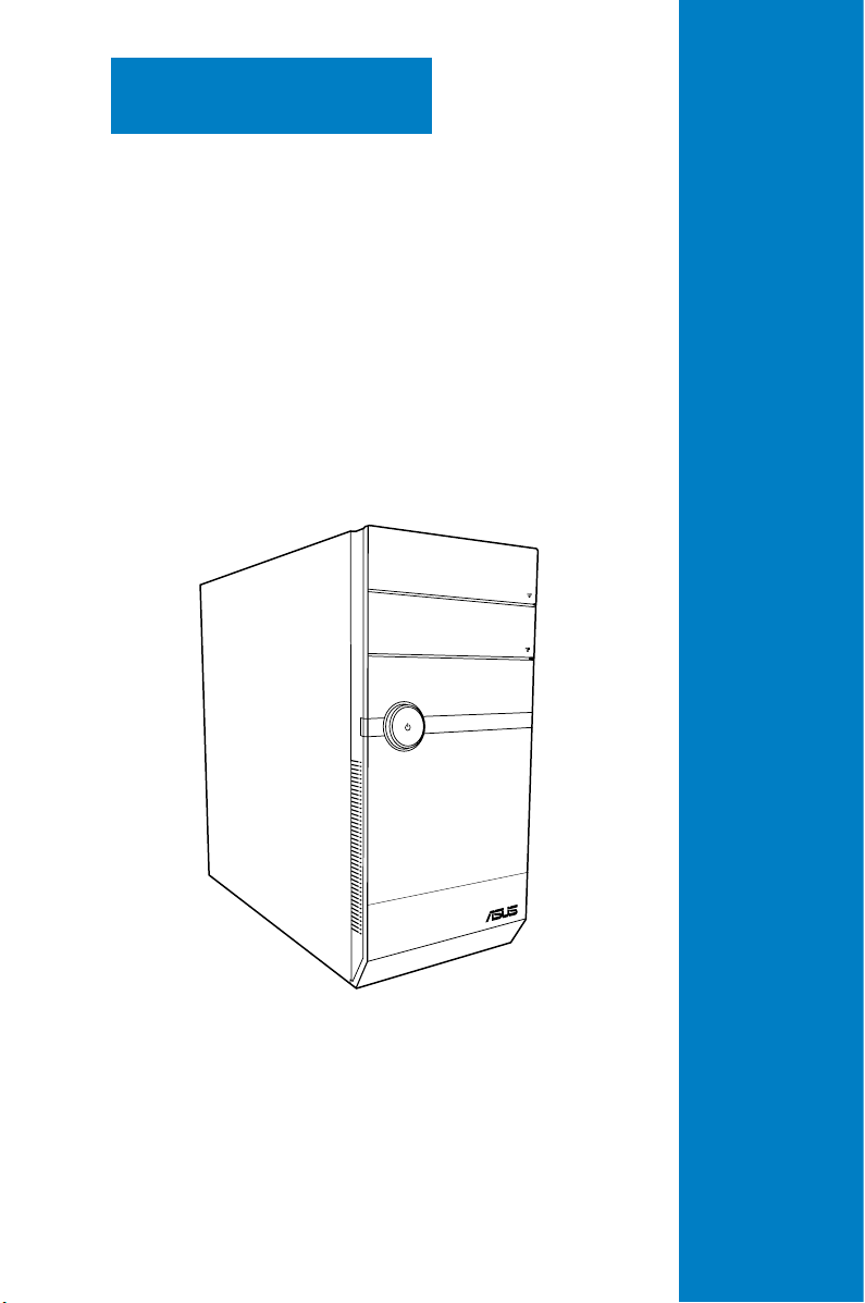
System introduction
This chapter gives a general
description of the ASUS
V7-series P5G43M. The chapter
lists the system features including
introduction on the front and rear panel,
and internal components.
Chapter 1
1-2 Chapter 1: System introduction
1.1 Welcome!
Thank you for choosing the ASUS V7-series P5G43M!
The ASUS V7-series P5G43M is an all-in-one barebone system with a versatile
home entertainment feature.
The system comes in a stylish casing and powered by the ASUS motherboard that
supports the Intel
®
Core™2 Extreme / Core™2 Duo / Core™2 Quad / Pentium
®
dual-core / Celeron
®
processors in the 775-land package.
The system supports up to 8 GB of system memory using DDR2-1066/800/667
DIMMs. High-resolution graphics via integrated graphics controller or PCI Express
x16 slot, Serial ATA, USB 2.0, and 8-channel audio feature the system and take
you ahead in the world of power computing.
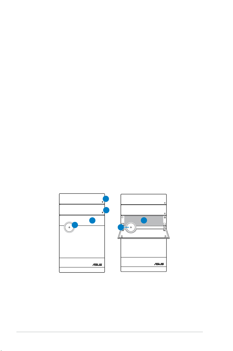
1.2 Front panel
The front panel includes the optical drive bays, power button, and several I/O ports
are located at the front panel.
1.2.1 V7-P5G43Mfrontpanel
4
1
4
5
2
3

1-3ASUS V7-series P5G43M
1. Push button. Press this button to open the front panel cover.
2. Push button
. Press this button to open the front panel cover.
3. Front panel cover.
These bays are for 5.25-inch IDE/SATA optical drivers
and 3.5-inch hard disk drivers.
4. Power button.
Press this button to turn the system on.
5. CF/MemoryStick
®
/,Memory Stick Pro™ card slot Secure Digital™/Multimedia
Card slot
1-4 Chapter 1: System introduction
SPDIF OUT
DVI
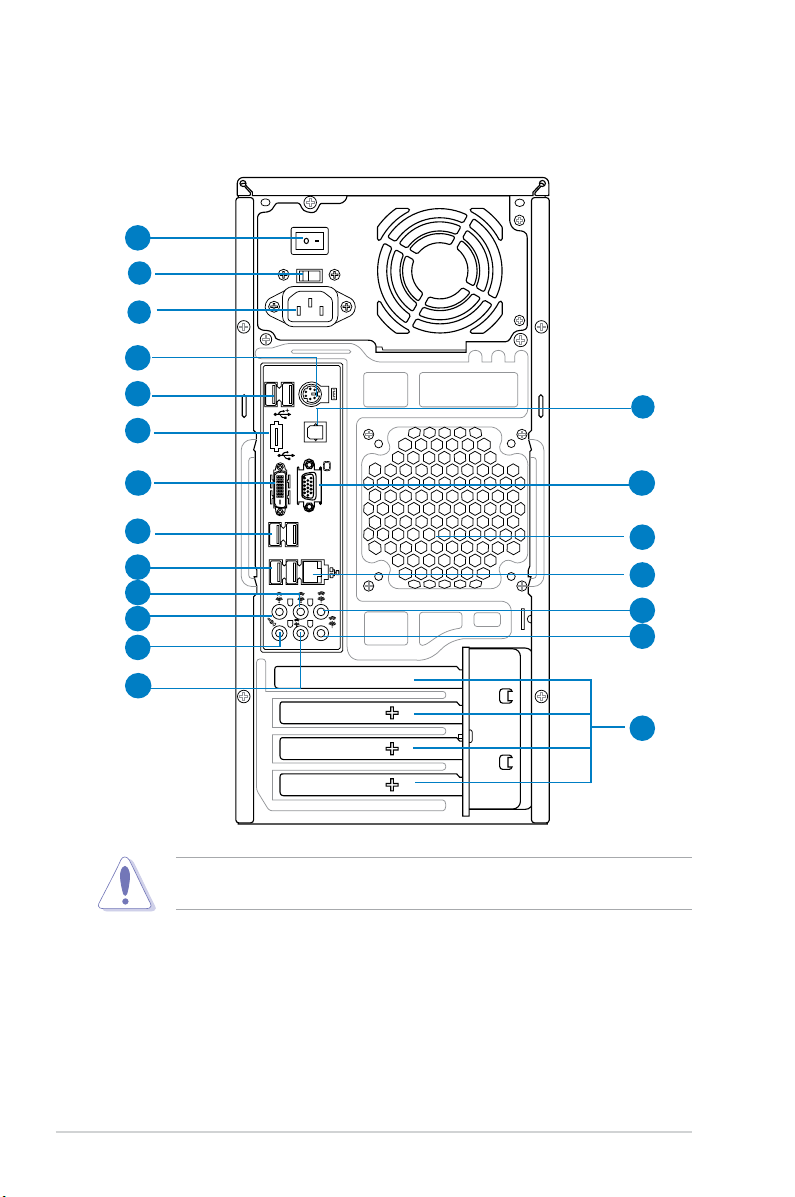
1.3 Rear panel
The system rear panel includes the power connector and several I/O ports that
allow convenient connection of devices.
1. Voltageselector.
This switch allows you to adjust the system input voltage
according to the voltage supply in your area. See the section “Voltage
selector” on page 1-7 before adjusting this switch.
2. Power connector.
This connector is for the power cable and plug.
3. Chassis fan vent.
This vent is for the fan that provides ventilation inside the
system chassis.
2
1
7
10
12
6
3
11
8
13
4
9
5
Do NOT cover the rear vent , and the ambient temperature is limited up to 35
o
C
to prevent the system from overheating.
14
15
16
17
18
19
20
1-5ASUS V7-series P5G43M
4. PS/2 mouse/keyboard port. This 6-pin connector is for a PS/2 mouse and
keyboard.
5. USB 2.0 ports.
These 4-pin Universal Serial Bus (USB) ports are available
for connecting USB 2.0 devices.
6. Optical S/PDIF Out port.
This port connects an external audio output device
via an optical S/PDIF cable.
7. HDMI port.
This port is for a High-Denition Multimedia Interface (HDMI)
connector, and is HDCP compliant allowing playback of HD DVD, Blu-Ray
and other protected content.
8. DVI-DOutport.
This port is for any DVI-D compatible device and is HDCP
compliant allowing playback of HD DVD, Blu-Ray and other protected
content.
9. VideoGraphicsAdapter(VGA)port.
This 15-pin port is for a VGA monitor
or other VGA-compatible devices.
10. USB 2.0 ports.
These 4-pin Universal Serial Bus (USB) ports are available
for connecting USB 2.0 devices.
11. USB 2.0 ports.
These 4-pin Universal Serial Bus (USB) ports are available
for connecting USB 2.0 devices.
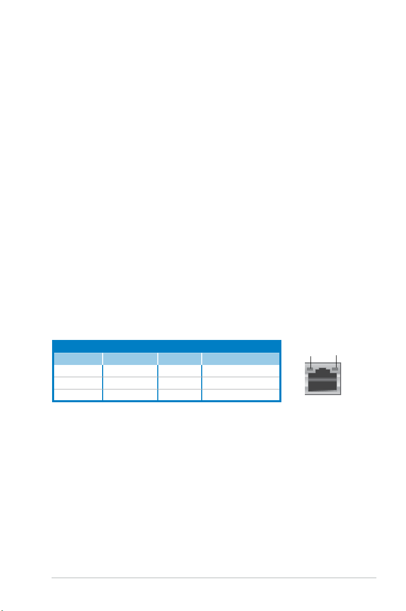
12. LAN(RJ-45)port.
This port allows gigabit connection to a Local Area
Network (LAN) through a network hub. Refer to the table below for the LAN
port LED indications.
Activity/Link SpeedLED
Status Description Status Description
OFF No link OFF 10 Mbps connection
ORANGE Linked ORANGE 100 Mbps connection
BLINKING Data activity GREEN 1 Gbps connection
LANportLEDindications
SPEED
LED
ACT/LINK
LED
LANport
13. RearSpeakerOutport(black).
This port connects the rear speakers in a
4-channel, 6-channel, or 8-channel audio conguration.
14. SideSpeakerOutport(gray).
This port connects the side speakers in an
8-channel audio conguration.
15. Microphoneport(pink).
This port connects a microphone.
16. LineOutport(lime).
This port connects a headphone or a speaker. In
4-channel, 6-channel, and 8-channel conguration, the function of this port
becomes Front Speaker Out.
17. Center/Subwooferport(orange).
This port connects the center/subwoofer
speakers.
1-6 Chapter 1: System introduction
Refer to the audio conguration table below for the function of the audio ports in
2, 4, 6, or 8-channel conguration.
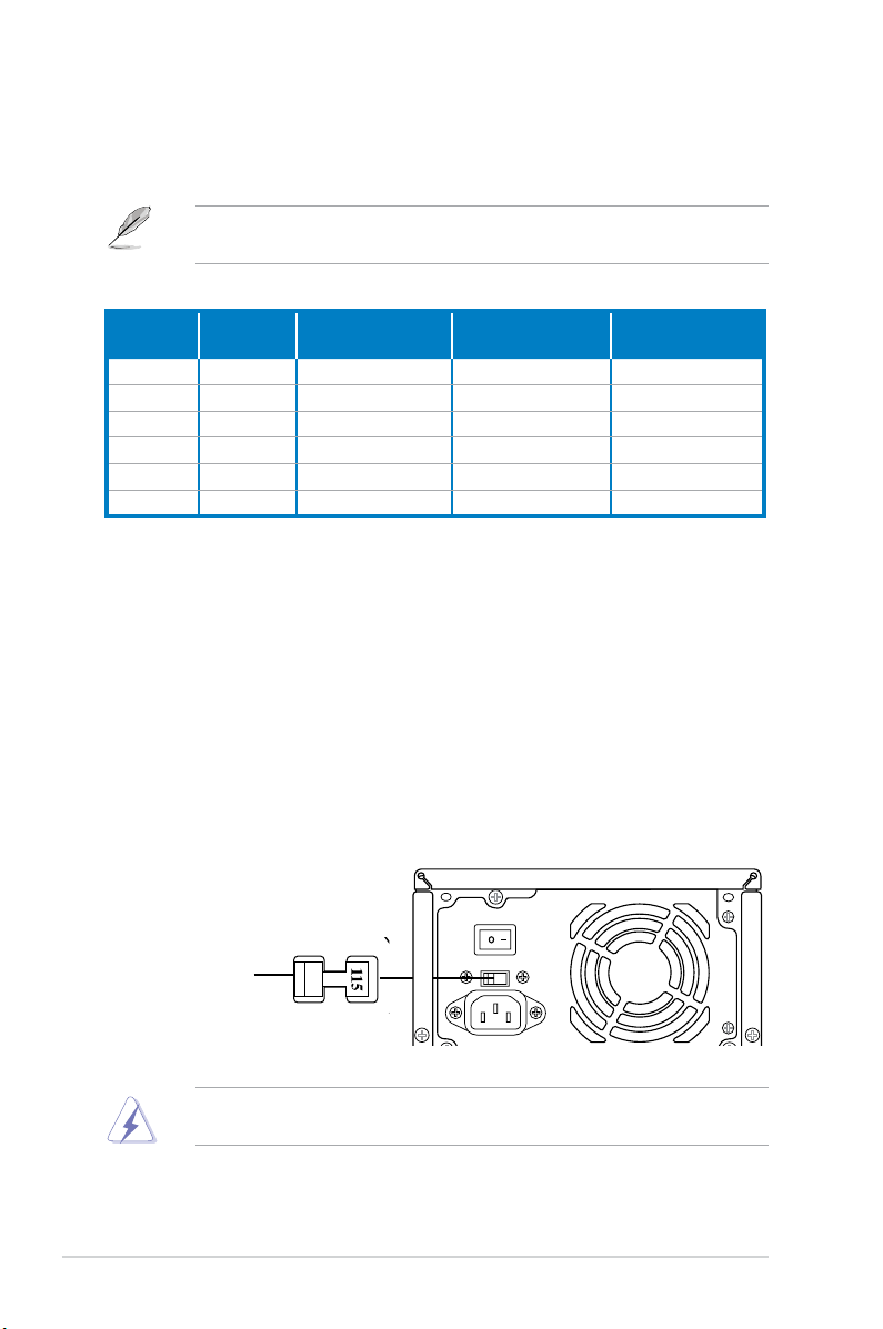
Voltageselector
The PSU has a 115 V/230 V voltage selector switch located beside the power
connector. Use this switch to select the appropriate system input voltage according
to the voltage supply in your area.
If the voltage supply in your area is 100-127 V, set this switch to 115 V.
If the voltage supply in your area is 200-240 V, set this switch to 230 V.
Setting the switch to 115V in a 230V environment or 230V in a 115V
environment will seriously damage the system!
18. LineInport(lightblue).
This port connects the tape, CD, DVD player, or
other audio sources.
Audio2,4,6,or8-channelconguration
Port
Headset
2-channel
4-channel 6-channel 8-channel
Light Blue Line In Line In Line In Line In
Lime Line Out Front Speaker Out Front Speaker Out Front Speaker Out
Pink Mic In Mic In Mic In Mic In
Orange – – Center/Subwoofer Center/Subwoofer
Black – Rear Speaker Out Rear Speaker Out Rear Speaker Out
Gray – – – Side Speaker Out
19. Expansion slot covers.
Remove these covers when installing expansion
cards.
20. Power Switch. This switch is for switching on/off the power supply unit.
115V/230V
Voltageselector
1-7ASUS V7-series P5G43M
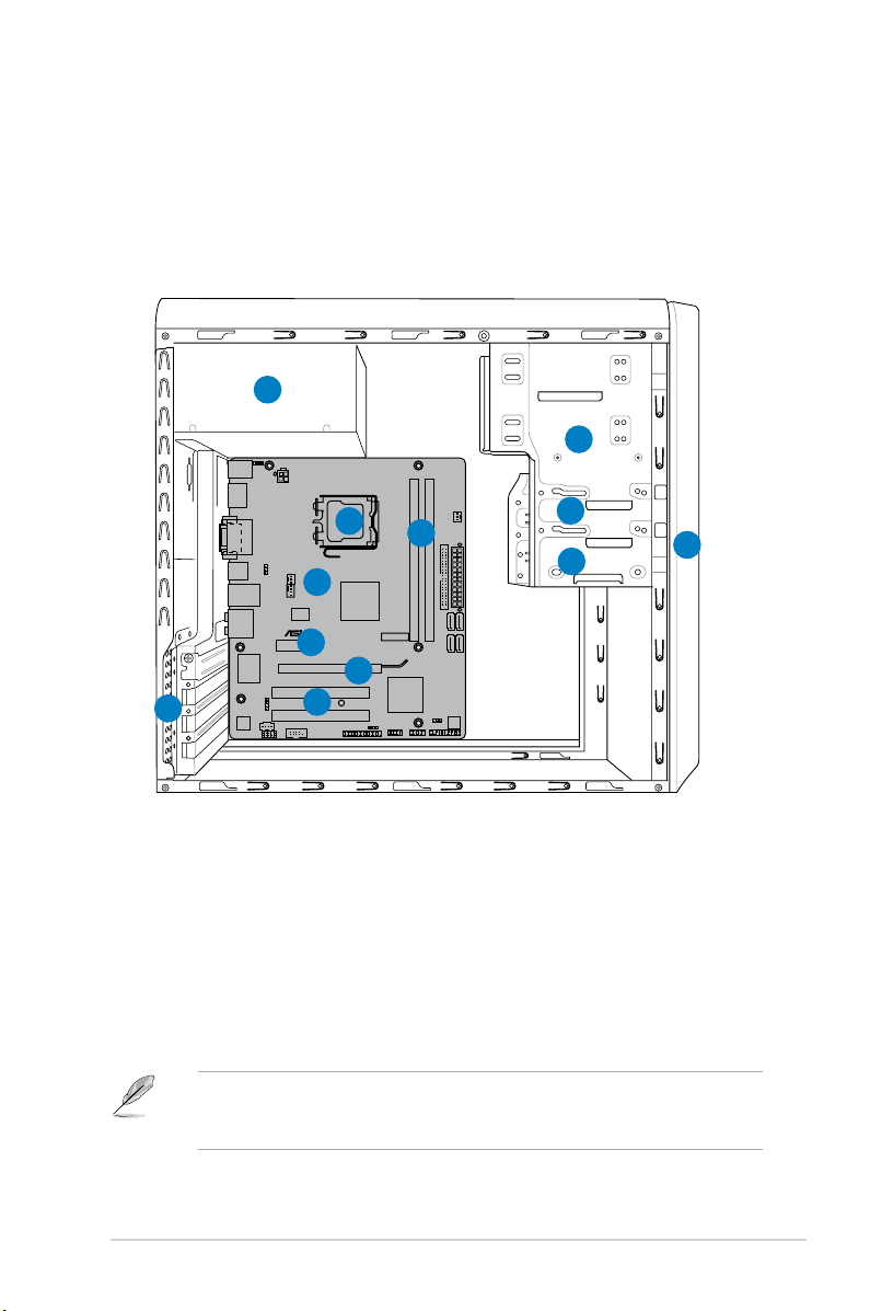
1.4 Internal components
The illustration below is the internal view of the system when you remove the side
cover and the power supply unit. The installed components are labeled for your
reference.
1. Front panel cover
2. 5.25-inch optical drive bays
3. 3.5-inch drive bay
4. Hard disk drive bay
5. Power supply unit
6. CPU socket
7. DIMM sockets
8. ASUS motherboard
9. PCI Express x16 slot
10. PCI Express x1 slot
11. PCI slots
12. Metal bracket lock
P5QPL-VM EPU
1
4
2
3
5
6
7
8
9
10
11
12
Refer to the bundled Quick Installation Guide for installing additional system
components and get assistance from professionals when you disassemble or
assemble the system.
1-8 Chapter 1: System introduction
1.5 QualiedVendorsLists(QVL)
DDR2-1066MHz capability
Vendor Part No. Size
SS/
DS
Brand Chip NO.
Timing
DIMM
(BIOS)
Voltage
DIMM
Support
A* B*
Crucial BL12864AA1065.8FE5 1024MB SS N/A Heat-Sink Package • •
Crucial CT25664AA1067.16FE1 2048MB DS Micron 9DJKH D9JKH 7-7-7-13 • •
G.SKILL F2-8500CL5D-2GBPI 2048MB(kit of 2) SS N/A Heat-Sink Package 5-5-5-15 2.1V • •
G.SKILL F2-8500CL5S-1GBPK 1024MB DS N/A Heat-Sink PackageSN:
815130037562
5-5-5-15 • •
G.SKILL F2-8500CL5D-2GBPK 2048MB(Kit of 2) DS N/A Heat-Sink Package 5-5-5-15 • •
G.SKILL F2-8500CL5D-4GBPI-B 4096MB(Kit of 2) DS N/A Heat-Sink Package • •
G.SKILL F2-8500CL5D-4GBPI 4096MB(Kit of 2) DS N/A Heat-Sink Package 5-5-5-15 2.0 ~ 2.1V • •
G.SKILL F2-8500CL5D-4GBPK 4096MB(kit of 2) DS N/A Heat-Sink Package 5-5-5-15 • •
GEIL
GB22GB8500C5DC 1024MB SS GEIL GL2L128M88BA25AB 5 • •
GEIL GB24GB8500C5QC 1024MB SS GEIL GL2L128M88BA25AB 5 • •
GEIL GE22GB1066C5DC 1024MB SS GEIL Heat-Sink Package 5 • •
GEIL GE24GB1066C5QC 1024MB SS GEIL Heat-Sink Package 5 • •
GEIL GB24GB8500C5DC 2048MB DS GEIL GL2L128M88BA25AB 5 • •
GEIL GE24GB1066C5DC 2048MB DS GEIL Heat-Sink Package 5 • •
GEIL GX24GB8500C5UDC 4096MB(kit of 2) DS N/A Heat-Sink Package 5 • •
kingmax KLED48F-B8KU6-NGES 1024MB SS kingmax KKB8FNUXF-DXX-18A 6-6-6-24 1.9V • •
kingmax KLEE88F-B8KU6-NNAS 2048MB DS kingmax KKB8FNUXF-DXX-18A 6-6-6-24 1.9V • •
Kingston KHX8500D2K2/1G 1024MB(Kit of 2) SS N/A Heat-Sink Package 5-5-5-15 2.2V • •
Kingston KHX8500D2K2/1GN(EPP) 1024MB(Kit of 2) SS Kingston Heat-Sink Package 5-5-5-18 1.8V • •
Kingston KHX8500D2K2/2GN(EPP) 1024MB DS Kingston Heat-Sink Package 5-5-5-18 1.8V • •
Kingston KVR1066D2N7/1G 1024MB DS Elpida E5108AJBG-1J-E 7 1.8V • •
Kingston KHX8500D2K2/2G 2048MB(Kit of 2) DS N/A Heat-Sink Package 5-5-5-15 2.2V • •
Kingston KHX8500D2K2/4G 2048MB(Kit of 2) DS N/A Heat-Sink Package 5-5-5-15 2.2V • •
OCZ OCZ2N10662GK(Epp) 2048MB(Kit of 2) DS N/A Heat-Sink Package 5-5-5-15 21.V • •
OCZ OCZ2N1066SR2DK(Epp) 2048MB(Kit of 2) DS OCZ Heat-Sink Package
004820806001601-2
5-5-5-15 2.1 - 2.3V • •
OCZ OCZ2P10664GK 2048MB DS N/A Heat-Sink Package • •
OCZ OCZ2F10664GK 4096MB(kit of 2) DS N/A Heat-Sink Package 6-7-7-20 2.2V • •
OCZ OCZ2RPR10664GK 4096MB(kit of 2) DS N/A Heat-Sink Package 5-5-5-15 2.2V • •
PSC AL8E8G73F-AE1 2048MB DS PSC A3R1GE3FGF907M
AT0FTAIWAN-G8E
5-5-5-12 • •
Qimonda HYS64T128000EU-1.9-C2 1024MB DS Qimonda HYB18T1G800C2F-
1.9FSS25253
• •
Transcend TX1066QLU-2GK 2048MB(Kit of 2) SS N/A Heat-Sink Package 5 • •
Transcend TX1066QLU-4GK 4096MB(kit of 2) DS Transcend Heat-Sink Package 5 • •
AENEON AXT760UD00-19DC97X 2048MB(Kit of 2) DS Heat-Sink Package • •
AENEON AXT860UD20-19E 4096MB(Kit of 2) DS AENEON Heat-Sink Package 6 • •
Elixir M2Y1G64TU88D5B-BD 1024MB SS Elixir M2TU1G800E-BD 5 • •
Mushkin 996612 2048MB(kit of 2) DS N/A Heat-Sink Package 5-5-5-15 2.1V • •
Mushkin 996619 4096MB(kit of 2) DS N/A Heat-Sink Package 5-5-5-15 2.1V • •
1-9ASUS V7-series P5G43M
DDR2-800MHz capability
Vendor Part No. Size
SS/
DS
Brand ChipNO.
Timing
DIMM
(BIOS)
Voltage
DIMM Support
A* B* C*
A-Data M2GVD6G3H3160Q1E52 512MB SS VDATA VD29608A8A-25EG20813 • • •
A-Data M2OAD6G3H3160Q1E58 512MB SS ADATA AD29608A8A-25EG80812 • • •
A-Data
AD2800E001GOU 2048MB(Kitof2)
SS N/A
Heat-SinkPackage
4-4-4-12
• •
•
A-Data M2GVD6G314170Q1E58
1024MB
DS VDATA
VD29608A8A-25EG80813
• •
A-Data AD2800E002GOU 4096MB(Kitof2) DS N/A Heat-SinkPackage 4-4-4-12 1.9~2.1V • • •
Apacer 78.91G91.9K5 512MB SS Apacer AM4B5708JQJS8E0751C 5 • •
Apacer 78.01GA0.9K5 1024MB SS Apacer AM4B5808CQJS8E0749D 5 • •
Apacer 78.A1GA0.9K4 2048MB DS Apacer AM4B5808CQJS8E0740E 5 • • •
Apacer 78.A1GA0.9K4 2048MB DS Apacer AM4B5808CQJS8E0747D 5 • •
Corsair CM2X1024-6400 1024MB DS Corsair Heat-SinkPackage • •
Corsair XMS2-6400 1024MB DS Corsair Heat-SinkPackage 4 • • •
Corsair XMS2-6400 1024MB DS Corsair Heat-SinkPackage 5 • •
Corsair CM2X2048-6400C5DHX 4096MB(Kitof2) DS N/A Heat-SinkPackage 5 • •
Corsair CM2X2048-6400C5 4096MB(Kitof2) DS N/A Heat-SinkPackage 5 • • •
Crucial BL12864AL80A.8FE5(EPP) 2048MB(kitof2) SS N/A Heat-SinkPackage 4-4-4-12 • • •
Crucial BL25664AL80A.16FE5(EPP) 4096MB(kitof2) DS N/A Heat-SinkPackage 4-4-4-12 • • •
Crucial BL25664AR80A.16FE5(EPP) 4096MB(kitof2) DS N/A Heat-SinkPackage 4-4-4-12 • • •
G.SKILL F2-6400CL5D-1GBNQ 512MB SS G.SKILL Heat-SinkPackageSN:
8151030036642
5-5-5-15 • • •
G.SKILL F2-6400CL4D-2GBPK 1024MB DS G.SKILL Heat-SinkPackage 4 • • •
G.SKILL F2-6400CL5D-2GBNQ 1024MB DS G.SKILL Heat-SinkPackage 5 • • •
G.SKILL F2-6400CL4D-4GBPK 2048MB DS G.SKILL Heat-SinkPackage 4 • • •
G.SKILL F2-6400CL5D-4GBPQ 2048MB DS G.SKILL Heat-SinkPackage 5 • •
G.SKILL F2-6400CL6Q-16GMQ 4096MB DS N/A Heat-SinkPackage 5 • • •
GEIL GB22GB6400C4DC 1024MB DS GEIL GL2L64M088BA30EB 5 • • •
GEIL GB22GB6400C5DC 1024MB DS GEIL GL2L64M088BA30EB 5 • • •
GEIL GB24GB6400C4QC 1024MB DS GEIL GL2L64M088BA30EB 4 • • •
GEIL GB24GB6400C5QC 1024MB DS GEIL GL2L64M088BA30EB 5 • • •
GEIL GE22GB800C4DC 1024MB DS GEIL Heat-SinkPackage 4 • • •
GEIL GE22GB800C5DC 1024MB DS GEIL Heat-SinkPackage 5 • • •
GEIL GE24GB800C4QC 1024MB DS GEIL Heat-SinkPackage 4 • • •
GEIL GE24GB800C5QC 1024MB DS GEIL Heat-SinkPackage 5 • •
GEIL GX22GB6400DC 1024MB DS GEIL Heat-SinkPackage 5 • • •
GEIL GX22GB6400UDC 1024MB DS GEIL Heat-SinkPackage 4 • •
GEIL GB24GB6400C4DC 2048MB DS GEIL GL2L128M88BA25AB 4 • •
GEIL GB24GB6400C5DC 2048MB DS GEIL GL2L128M88BA25AB 5 • • •
GEIL GB28GB6400C4QC 2048MB DS GEIL GL2L128M88BA25AB 4 • • •
GEIL GB28GB6400C5QC 2048MB DS GEIL GL2L128M88BA25AB 5 • • •
GEIL GE24GB800C4DC 2048MB DS GEIL Heat-SinkPackage 4 • • •
GEIL GE24GB800C5DC 2048MB DS GEIL Heat-SinkPackage 5 • • •
GEIL GE28GB800C4QC 2048MB DS GEIL Heat-SinkPackage 4 • •
GEIL GE28GB800C5QC 2048MB DS GEIL Heat-SinkPackage 5 • • •
GEIL GX22GB6400CUSC 2048MB DS GEIL Heat-SinkPackage 4 • •
GEIL GX22GB6400LX 2048MB DS GEIL Heat-SinkPackage 5 • • •
GEIL GX24GB6400DC 2048MB DS GEIL Heat-SinkPackage 5 • •
Kingmax KLDC28F-A8KI5 512MB SS Kingmax KKA8FF1XF-JFS-25A • •
Kingmax KKB8FFBXF-CFA-25U 1024MB SS Kingmax KLDD48F-B8KB5 • • •
kingmax KLDE88F-B8KB5 2048MB DS kingmax KKB8FFBXF-CFA-25U • • •
(continued on the next page)

1-10 Chapter 1: System introduction
DDR2-800MHz capability
Vendor Part No. Size
SS/
DS
Brand ChipNO.
Timing
DIMM
(BIOS)
Voltage
DIMM Support
A* B* C*
Kingston KVR800D2N6/ 512 512MB SS Elpida E5108AJBG-8E-E 6 1.8V • • •
Kingston KHX6400D2LLK2/1GN 1024M(Kitof2) SS Kingston Heat-SinkPackage 4-4-4-12 2.0V • • •
Kingston KHX6400D2LL/1G 1024MB DS Kingston Heat-SinkPackage 4-4-4-12 2.0V • • •
Kingston
KVR800D2N5/1G
1024MB DS
Kingston D6408TR4CGL25USL3624
06PECXA
5
1.8V •
• •
Kingston KVR800D2N6/1G 1024MB DS Elpida E5108AJBG-8E-E • •
Kingston KHX6400D2K2/2G 2048MB(Kitof2) DS N/A Heat-SinkPackage 5-5-5-15 2.0V • • •
Kingston 461625.010819 PTGC 2048MB DS Kingston KVR800D2N6/2G 6 1.8V • • •
Kingston KHX6400D2/2G 2048MB DS Kingston Heat-SinkPackage 5 1.8V • • •
Kingston KVR800D2N5/2G 2048MB DS Elpida E1108ACBG-8E-E 5 1.8V • • •
Kingston KVR800D2N6/4G 4096MB DS Elpida E2108ABSE-8G-E 6 • • •
OCZ OCZ2G800R22GK 1024MB DS OCZ Heat-SinkPackage 5 • • •
OCZ OCZ2P800R22GK 1024MB DS OCZ Heat-SinkPackage 4 • • •
OCZ OCZ2RPR8002GK 1024MB DS OCZ Heat-SinkPackage 4 • • •
OCZ OCZ2VU8004GK 1024MB DS OCZ Heat-SinkPackage 6 • • •
OCZ OCZ2SE8002GK 2048MB(Kitof2) DS N/A Heat-SinkPackage 5-5-5-15 1.8V • • •
OCZ OCZ2F8004GK 2048MB DS N/A Heat-SinkPackage 5 • •
PSC AL7E8F73C-8E1 1024MB SS PSC A3R1GE3CFF734MAA0E 5 • •
PSC AL8E8F73C-8E1 2048MB DS PSC A3R1GE3CFF734MAA0E 5 • • •
PSC SHG772-AA3G 2048MB DS PSC PL8E8F73C-8E1 • • •
PSC XCP271A3G-A 2048MB DS PSC PL8E8G73E-8E1 • •
Qimonda HYS64T256020EU-2.5-C2 2048MB DS Qimonda HY818T1G800C2F-2.5 5 • • •
Samsung K4T51083QG-HCF7 512MB SS Qimonda M378T6553GZS-CF7 6 • • •
Samsung K4T1G084QQ-HCF7 1024MB SS Qimonda M378T2863QZS-CF7 6 • •
Samsung K4T1G084QQ-HCF7 2048MB DS Samsung M37875663QZ3-CF7 6 • •
Samsung M378T5263AZ3-CF7 4096MB DS Samsung K4T2G084QA-HCF7 • • •
Super
Talent
T800UB1GC4 1024MB DS Super
Talent
Heat-SinkPackage 4 • •
Transcend TS64MLQ64V8J 512MB SS Micron 7HD22D9GMH 5 • • •
Transcend JM800QLU-1G 1024MB SS Transced TQ1243PCF8 5 • •
Transcend TS128MLQ64V8U 1024MB SS ELPIDA E1108ACBG-8E-E 5 • • •
Transcend JM800QLJ-1G 1024MB DS Transced TQ123PJF8F0801 5 • •
Transcend JM800QLJ-1G 1024MB DS Transcend TQ123YBF8T0747 5 • • •
Transcend TS128MLQ64V8J 1024MB DS Mircon 7HD22D9GMH 5 • • •
Transcend JM800QLU-2G 2048MB DS Transced TQ243PCF8 5 • •
Transcend TS256MLQ64V8U 2048MB DS Elpida E1108ACBG-8E-E 5 • • •
AENEON AET760UD00-25DC08X 1024MB SS AENEON AET03R250C0732 5 • • •
AENEON AET860UD00-25DC08X 2048MB DS AENEON AET03R25DC0732 5 • • •
ASINT SLY2128M8-JGE 1024MB SS ASINT DDRII1208-GE8115 • • •
ASINT SLZ2128M8-JGE 2048MB DS ASINT DDRII1208-GE8115 • • •
Century 28V0H8 1024MB DS Hynix HY5PS12821CFP-S5 5 • •
Elixir M2Y1G64TU88D5B-AC 0828.GS 1024MB SS Elixir N2TU16800E-AC • • •
ELIXIR M2Y1G64TU8HB0B-25C 1024MB DS ELIXIR N2TU51280BE-
25C802006Z1DV
5 • • •
Elixir M2Y2G64TU8HD5B-AC 0826.SG 2048MB DS Elixir N2TUG80DE-AC • • •
MDT MDT 512MB 512MB SS MDT 18D51280D-2.50726F 5 • • •
MDT MDT 1024MB 1024MB DS MDT 18D51280D-2.50726E 5 • •
TAKEMS TMS51B264C081-805EP 512MB SS takeMS MS18T51280-2.5P0710 5 • • •
TAKEMS TMS1GB264C081-805EP 1024MB DS takeMS MS18T51280-2.5P0716 5 • •
UMAX D48001GP3-63BJU 1024MB DS UMAX U2S12D30TP-8E • • •
UMAX D48002GP0-73BCU 2048MB DS UMAX U2S24D30TP-8E 5 • • •
1-11ASUS V7-series P5G43M
DDR2-667MHz capability
Vendor Part No. Size
SS/
DS
Brand ChipNO.
Timing
DIMM
(BIOS)
Voltage
DIMM
Support
A* B* C*
A-Data M2OAD5H3J4170I1C53 2048MB DS ADATA AD20908A8A-3EG30724 • • •
Apacer 78.91G92.9K5 512MB SS Apacer AM4B5708JQJS7E0751C 5 • • •
Apacer AU512E667C5KBGC 512MB SS Apacer AM4B5708GQJS7E06332F 5 • •
Apacer AU512E667C5KBGC 512MB SS Apacer AM4B5708MIJS7E0627B 5 • •
Apacer 78.01G9O.9K5 1024MB SS Apacer AM4B5808CQJS7E0751C 5 • • •
Apacer AU01GE667C5KBGC 1024MB DS Apacer AM4B5708GQJS7E0636B • • •
Apacer AU01GE667C5KBGC 1024MB DS Apacer AM4B5708MIJS7E0627B 5 • •
Apacer AM4B5808CQJS7E0749B 2048MB DS Apacer 78.A1G9O.9K4 5 • • •
Corsair VS512MB667D2 512MB DS Corsair MIII0052532M8CEC • •
Corsair VS1GB667D2 1024MB DS Corsair MID095D62864M8CEC • •
Corsair XMS2-5400 1024MB DS Corsair Heat-SinkPackage 4 • • •
G.SKILL F2-5400PHU2-2GBNT 2048MB(Kitof2) DS G.SKILL D264M8CCF0815C7173S 5-5-5-15 • • •
G.SKILL F2-5300CL5D-4GBMQ 4096MB(Kitof2) DS G.SKILL Heat-SinkPackageSN:
8151030036559
5-5-5-15 • •
GEIL GX21GB5300SX 1024MB DS GEIL Heat-SinkPackage 3 • •
GEIL GX22GB5300LX 2048MB DS GEIL Heat-SinkPackage 5 • •
GEIL GX24GB5300LDC 2048MB DS GEIL Heat-SinkPackage 5 • • •
Kingmax KLCC28F-A8KB5 512MB SS Kingmax KKEA88B4LAUG-29DX • • •
Kingmax KLCD48F-A8KB5 1024MB DS Kingmax KKEA88B4LAUG-29DX • • •
Kingston KVR667D2N5/512 512MB SS Kingston SO1237650821SBPD6408TR
4CGL25USL074905PECNB
5 1.8V • • •
Kingston KVR667D2N5/1G 1024MB DS Kingston SO1280420822SOPD6408TR
4CGL25USL156304PECXA
5 1.8V • • •
Kingston KVR667D2N5/2G 2048MB DS Micron 7RE22D9HNL 5-5-5-15 2.0V • • •
Kingston KVR667D2N5/2G 2048MB DS ELPIDA E1108ACBG-8E-E0813A90CC 5 1.8V • • •
Micron MT8HTF12864AY-667E1 1024MB SS Micron D9HNL7ZE17 5 • •
PSC AL6E8E63J-6E1 512MB SS PSC A3R12E3JFF717B9A00 5 • • •
PSC AL7E8F73C-6E1 1024MB SS PSC A3R1GE3CFF734MAA0J 5 • • •
PSC AL6E8E63J-6E1 1024MB DS PSC A3R12E3JFF717B9A01 5 • • •
PSC AL8E8F73C-6E1 2048MB DS PSC A3R1GE3CFF733MAA00 5 • • •
Samsung M378T5263AZ3-CE6 4096MB DS Samsung K4T2G084QA-HCE6 • • •
T667UB1GV 1024MB DS SuperTalent PG64M8-8000750 5 • • •
Transcend JM667QLU-1G 1024MB SS Transced TQ243PCF8T0838 5 • • •
Transcend JM667QLJ-1G 1024MB DS Elpida E5108AJBG-6E-E 5 • • •
Transcend JM667QLU-2G 2048MB DS Transced TQ243PCF8T0834 5 • • •
Twinmos 8D-A3JK5MPETP 512MB SS PSC A3R12E3GEF633ACAOY 5 • • •
AENEON AET860UD00-30DB08X 2048MB DS AENEON AET03F30DB0730 5 • • •
Asint SLX264M8-J6E 512MB SS Asint DDRII6408-6E • • •
ASINT SLY2128M8-J6E 1024MB SS ASINT DDRII1208-6E8115 • • •
Century CENTURY512MB 512MB SS Hynix HY5PS12821AFP-Y5 • •
Century CENTURY512MB 512MB SS Nanya NT5TU64M8AE-3C • • •
Century CENTURY1G 1024MB DS Hynix HY5PS12821AFP-Y5 • • •
Century CENTURY1G 1024MB DS Nanya NT5TU64M8AE-3C • •
ELIXIR M2Y1G64TU8HA2B-3C 1024MB DS elixir M2TU51280AE-
3C717095R28F
5 1.7-1.9v • • •
Elixir M2Y1G64TU8HBOB-3C 1024MB DS Elixir N2TU51280BE-
3C639009W1CF
5 • • •
KINGBOX 512MB667MHz 512MB SS KINGBOX EPD264082200-4 • • •
KINGBOX DDRII1G667MHz 1024MB DS KINGBOX EPD264082200-4 • • •
Leadmax LRMP512U64A8-Y5 1024MB DS Hynix HY5PS12821CFP-Y5C702AA 5 • • •
(continued on the next page)
1-12 Chapter 1: System introduction
DDR2 667MHz capability
SS - Single-sided / DS - Double-sided
DIMM support:
• A*: Supports one module inserted in any slot as Single-channel
memory conguration.
• B*: Supports one pair of modules inserted into either the yellow slots
or the black slots as one pair of Dual-channel memory conguration.
• C*: Supports four modules inserted into both the yellow and black slots
as two pairs of Dual-channel memory conguration.
Visit the ASUS website at http://support.asus.com for the latest QVL.
Vendor Part No. Size
SS/
DS
Brand ChipNO.
Timing
DIMM
(BIOS)
Voltage
DIMM
Support
A* C*
MDT DDRII512PC667 512MB DS MDT 18D51201D-30726E 4 • • •
MDT MDT1024MB 1024MB DS MDT 18D51280D-30646E 4 • • •
TAKEMS TMS51B264C081-665AP 512MB SS takeMS MS18T51280-3S0627D 5 • • •
TAKEMS TMS51B264C081-665QI 512MB SS takeMS MS18T51280-3 5 • • •
TAKEMS TMS1GB264C081-665AE 1024MB DS takeMS MS18T51280-3SEA07100 5 • •
TAKEMS TMS1GB264C081-665AP 1024MB DS takeMS MS18T51280-3SP0717A 5 • • •
TAKEMS TMS1GB264C081-665QI 1024MB DS takeMS MS18T51280-3 5 • •
TEAM TVDD1.02M667C4 1024MB DS TEAM T2D648PT-6 • •
UMAX D46701GP3-63BJU 1024MB DS UMAX U2S12D30YP-6E • • •
UMAX D46702GP0-73BCU 2048MB DS UMAX U2S24D30TP-6E 5 • •
This chapter helps you power up the
system and install drivers and utilities
from the support DVD.
Chapter 2
Starting up
2-2 Chapter 2: Starting up
2.1 Installing an operating system
The barebone system supports Windows
®
XP/Vista operating systems (OS).
Always install the latest OS version and corresponding updates so you can
maximize the features of your hardware.
2.3 Support DVD information
The support DVD that came with the system contains useful software and several
utility drivers that enhance the system features.
2.2 Powering up
Press the system power button ( ) to enter the OS.
Motherboard settings and hardware options vary. Use the setup procedures
presented in this chapter for general reference only. Refer to your OS
documentation for more information.
•
Screen display and driver options may not be the same for different
operating system versions.
•
The contents of the support DVD are subject to change at any time without
notice. Visit the ASUS website at www.asus.com for updates.
• Windows XP OS setup cannot recognize Serial ATA hard drives in a RAID
set without the necessary drivers. Use a RAID driver disk when installing
Windows XP OS to a Serial ATA hard drive included in a RAID set.
• From the Windows XP setup screen, press F6 when prompted then follow
succeeding screen instructions to install the SATA drivers.
Press to turn ON the system
 Loading...