


 Loading...
PRIME X399-A
Motherboard

E13889
Revised Edition V3
January 2018
Copyright© 2018 ASUSTeK COMPUTER INC. All Rights Reserved.
No part of this manual, including the products and software described in it, may be reproduced, transmitted, transcribed, stored in a retrieval system, or translated into any language in any form or by any means, except documentation kept by the purchaser for backup purposes, without the express written permission of ASUSTeK COMPUTER INC. (“ASUS”).
Product warranty or service will not be extended if: (1) the product is repaired, modified or altered, unless such repair, modification of alteration is authorized in writing by ASUS; or (2) the serial number of the product is defaced or missing.
ASUS PROVIDES THIS MANUAL “AS IS” WITHOUT WARRANTY OF ANY KIND, EITHER EXPRESS OR IMPLIED, INCLUDING BUT NOT LIMITED TO THE IMPLIED WARRANTIES OR CONDITIONS OF MERCHANTABILITY OR FITNESS FOR A PARTICULAR PURPOSE. IN NO EVENT SHALL ASUS, ITS DIRECTORS, OFFICERS, EMPLOYEES OR AGENTS BE LIABLE FOR ANY INDIRECT, SPECIAL, INCIDENTAL, OR CONSEQUENTIAL DAMAGES (INCLUDING DAMAGES FOR LOSS OF PROFITS, LOSS OF BUSINESS, LOSS OF USE OR DATA, INTERRUPTION OF BUSINESS AND THE LIKE), EVEN IF ASUS HAS BEEN ADVISED OF THE POSSIBILITY OF SUCH DAMAGES ARISING FROM ANY DEFECT OR ERROR IN THIS MANUAL OR PRODUCT.
SPECIFICATIONS AND INFORMATION CONTAINED IN THIS MANUAL ARE FURNISHED FOR INFORMATIONAL USE ONLY, AND ARE SUBJECT TO CHANGE AT ANY TIME WITHOUT NOTICE, AND SHOULD NOT BE CONSTRUED AS A COMMITMENT BY ASUS. ASUS ASSUMES NO RESPONSIBILITY OR LIABILITY FOR ANY ERRORS OR INACCURACIES THAT MAY APPEAR IN THIS MANUAL, INCLUDING THE PRODUCTS AND SOFTWARE DESCRIBED IN IT.
Products and corporate names appearing in this manual may or may not be registered trademarks or copyrights of their respective companies, and are used only for identification or explanation and to the owners’ benefit, without intent to infringe.
Offer to Provide Source Code of Certain Software
This product contains copyrighted software that is licensed under the General Public License (“GPL”), under the Lesser General Public License Version (“LGPL”) and/or other Free Open Source Software Licenses. Such software in this product is distributed without any warranty to the extent permitted by the applicable law. Copies of these licenses are included in this product.
Where the applicable license entitles you to the source code of such software and/or other additional data, you may obtain it for a period of three years after our last shipment of the product, either
(1)for free by downloading it from https://www.asus.com/support/
or
(2)for the cost of reproduction and shipment, which is dependent on the preferred carrier and the location where you want to have it shipped to, by sending a request to:
ASUSTeK Computer Inc.
Legal Compliance Dept.
15 Li Te Rd.,
Beitou, Taipei 112
Taiwan
In your request please provide the name, model number and version, as stated in the About Box of the product for which you wish to obtain the corresponding source code and your contact details so that we can coordinate the terms and cost of shipment with you.
The source code will be distributed WITHOUT ANY WARRANTY and licensed under the same license as the corresponding binary/object code.
This offer is valid to anyone in receipt of this information.
ASUSTeK is eager to duly provide complete source code as required under various Free Open Source Software licenses. If however you encounter any problems in obtaining the full corresponding source code we would be much obliged if you give us a notification to the email address gpl@asus.com, stating the product and describing the problem (please DO NOT send large attachments such as source code archives, etc. to this email address).
ii

Contents
Safety information....................................................................................................... |
v |
About this guide.......................................................................................................... |
vi |
PRIME X399-A specifications summary................................................................. |
viii |
Package contents...................................................................................................... |
xii |
Installation tools and components.......................................................................... |
xiii |
Chapter 1: |
Product Introduction |
|
|
1.1 |
Motherboard overview............................................................................... |
1-1 |
|
|
1.1.1 |
Before you proceed..................................................................... |
1-1 |
|
1.1.2 |
Motherboard layout...................................................................... |
1-2 |
|
1.1.3 |
Central Processing Unit (CPU).................................................... |
1-4 |
|
1.1.4 |
System memory........................................................................... |
1-5 |
|
1.1.5 |
Expansion slots............................................................................ |
1-7 |
|
1.1.6 |
Jumpers, buttons and holes......................................................... |
1-9 |
|
1.1.7 |
Onboard LEDs........................................................................... |
1-11 |
|
1.1.8 |
Internal connectors.................................................................... |
1-17 |
Chapter 2: |
Basic Installation |
|
|
2.1 |
Building your PC system........................................................................... |
2-1 |
|
|
2.1.1 |
CPU installation........................................................................... |
2-1 |
|
2.1.2 |
CPU heatsink and fan assembly installation................................ |
2-3 |
|
2.1.3 |
Motherboard installation.............................................................. |
2-4 |
|
2.1.4 |
DIMM installation......................................................................... |
2-6 |
|
2.1.5 |
ATX power connection................................................................. |
2-7 |
|
2.1.6 |
SATA device connection.............................................................. |
2-8 |
|
2.1.7 |
Front I/O connector...................................................................... |
2-9 |
|
2.1.8 |
Expansion card installation........................................................ |
2-10 |
|
2.1.9 |
M.2 installation........................................................................... |
2-11 |
2.2 |
BIOS update utility.................................................................................... |
2-12 |
|
2.3 |
Motherboard rear and audio connections.............................................. |
2-13 |
|
|
2.3.1 |
Rear I/O connection................................................................... |
2-13 |
|
2.3.2 |
Audio I/O connections................................................................ |
2-15 |
2.4 |
Starting up for the first time.................................................................... |
2-17 |
|
2.5 |
Turning off the computer......................................................................... |
2-17 |
|
Chapter 3: |
BIOS Setup |
|
|
3.1 |
Knowing BIOS............................................................................................. |
3-1 |
|
3.2 |
BIOS setup program................................................................................... |
3-2 |
|
|
3.2.1 |
EZ Mode...................................................................................... |
3-3 |
|
3.2.2 |
Advanced Mode........................................................................... |
3-4 |
|
3.2.3 |
QFan Control............................................................................... |
3-7 |
|
3.2.4 |
EZ Tuning Wizard........................................................................ |
3-8 |
iii

3.3 |
My Favorites.............................................................................................. |
3-10 |
|
3.4 |
Main menu................................................................................................. |
3-12 |
|
3.5 |
Ai Tweaker menu...................................................................................... |
3-12 |
|
3.6 |
Advanced menu........................................................................................ |
3-13 |
|
|
3.6.1 |
Trusted Computing.................................................................... |
3-13 |
|
3.6.2 |
AMD fTPM Configuration........................................................... |
3-13 |
|
3.6.3 |
SATA Configuration................................................................... |
3-13 |
|
3.6.4 |
Onboard Devices Configuration................................................. |
3-14 |
|
3.6.5 |
APM Configuration..................................................................... |
3-15 |
|
3.6.6 |
CPU Configuration..................................................................... |
3-16 |
|
3.6.7 |
Network Stack Configuration..................................................... |
3-16 |
|
3.6.8 |
HDD/SSD SMART Information.................................................. |
3-16 |
|
3.6.9 |
USB Configuration..................................................................... |
3-16 |
|
3.6.10 |
AMD PBS................................................................................... |
3-17 |
3.7 |
Monitor menu............................................................................................ |
3-17 |
|
3.8 |
Boot menu................................................................................................. |
3-18 |
|
3.9 |
Tool menu.................................................................................................. |
3-19 |
|
|
3.9.1 |
ASUS EZ Flash 3 Utility............................................................. |
3-19 |
|
3.9.2 |
Secure Erase............................................................................. |
3-20 |
|
3.9.3 |
ASUS Overclocking Profile........................................................ |
3-21 |
|
3.9.4 |
ASUS SPD Information.............................................................. |
3-21 |
|
3.9.5 |
Graphics Card Information......................................................... |
3-21 |
3.10 |
Exit menu................................................................................................... |
3-22 |
|
3.11 |
Updating BIOS.......................................................................................... |
3-23 |
|
|
3.11.1 |
EZ Update.................................................................................. |
3-23 |
|
3.11.2 |
ASUS EZ Flash 3....................................................................... |
3-24 |
|
3.11.3 |
ASUS CrashFree BIOS 3.......................................................... |
3-26 |
Chapter 4: |
RAID Support |
|
|
4.1 |
AMD RAID Array configurations............................................................... |
4-1 |
|
|
4.1.1 |
RAID definitions........................................................................... |
4-1 |
|
4.1.2 |
Installing storage devices............................................................ |
4-2 |
|
4.1.3 |
RaidXpert2 Configuration Utility in UEFI BIOS............................ |
4-2 |
4.2 |
Creating a RAID driver disk....................................................................... |
4-5 |
|
|
4.2.1 |
Creating a RAID driver disk in Windows® ................................... |
4-5 |
Appendix |
|
|
|
Notices |
..................................................................................................................... |
|
A-1 |
ASUS contact information...................................................................................... |
A-5 |
||
iv

Safety information
Electrical safety
•To prevent electrical shock hazard, disconnect the power cable from the electrical outlet before relocating the system.
•When adding or removing devices to or from the system, ensure that the power cables for the devices are unplugged before the signal cables are connected. If possible, disconnect all power cables from the existing system before you add a device.
•Before connecting or removing signal cables from the motherboard, ensure that all power cables are unplugged.
•Seek professional assistance before using an adapter or extension cord. These devices could interrupt the grounding circuit.
•Ensure that your power supply is set to the correct voltage in your area. If you are not sure about the voltage of the electrical outlet you are using, contact your local power company.
•If the power supply is broken, do not try to fix it by yourself. Contact a qualified service technician or your retailer.
Operation safety
•Before installing the motherboard and adding devices on it, carefully read all the manuals that came with the package.
•Before using the product, ensure all cables are correctly connected and the power cables are not damaged. If you detect any damage, contact your dealer immediately.
•To avoid short circuits, keep paper clips, screws, and staples away from connectors, slots, sockets and circuitry.
•Avoid dust, humidity, and temperature extremes. Do not place the product in any area where it may become wet.
•Place the product on a stable surface.
•If you encounter technical problems with the product, contact a qualified service technician or your retailer.
v

About this guide
This user guide contains the information you need when installing and configuring the motherboard.
How this guide is organized
This guide contains the following parts:
1.Chapter 1: Product Introduction
This chapter describes the features of the motherboard and the new technology it supports. It includes description of the switches, jumpers, and connectors on the motherboard.
2.Chapter 2: Basic Installation
This chapter lists the hardware setup procedures that you have to perform when installing system components.
3.Chapter 3: BIOS Setup
This chapter tells how to change system settings through the BIOS Setup menus. Detailed descriptions of the BIOS parameters are also provided.
4.Chapter 4: RAID Support
This chapter describes the RAID configurations.
Where to find more information
Refer to the following sources for additional information and for product and software updates.
1.ASUS website
The ASUS website (www.asus.com) provides updated information on ASUS hardware and software products.
2.Optional documentation
Your product package may include optional documentation, such as warranty flyers, that may have been added by your dealer. These documents are not part of the standard package.
vi

Conventions used in this guide
To ensure that you perform certain tasks properly, take note of the following symbols used throughout this manual.
DANGER/WARNING: Information to prevent injury to yourself when trying to complete a task.
CAUTION: Information to prevent damage to the components when trying to complete a task.
IMPORTANT: Instructions that you MUST follow to complete a task.
NOTE: Tips and additional information to help you complete a task.
Typography
Bold text |
Indicates a menu or an item to select. |
Italics |
Used to emphasize a word or a phrase. |
<Key> |
Keys enclosed in the less-than and greater-than sign |
|
means that you must press the enclosed key. |
|
Example: <Enter> means that you must press the Enter or |
|
Return key. |
<Key1> + <Key2> + <Key3> |
If you must press two or more keys simultaneously, the key |
|
names are linked with a plus sign (+). |
vii

PRIME X399-A specifications summary
CPU |
AMD SocketTR4 socket for AMD Ryzen™ Threadripper™ processors |
|
* Refer to www.asus.com for the CPU support list. |
||
|
||
|
|
|
Chipset |
AMD X399 |
|
|
|
|
|
AMD Ryzen™ Threadripper™ Processors |
|
|
- 8 x DIMM, max. 128GB, DDR4 3600+(O.C.)/3466(O.C.)/3333(O.C.)/3200(O.C.)/3 |
|
Memory |
000(O.C.)/2800(O.C.)/2666/2400/2133 MHz, ECC and non-ECC, un-buffered |
|
memory |
||
|
- Quad channel memory architecture |
|
|
* Please refer to Memory QVL (Qualified Vendors List) for details. |
|
|
|
|
|
AMD Ryzen™ Threadripper™ Processors |
|
Expansion |
- 4 x PCIe 3.0 x16 slots (support x16/x8/x16/x8) |
|
AMD X399 chipset |
||
slots |
||
- 1 x PCIe 2.0 x4 slot |
||
|
||
|
- 1 x PCIe 2.0 x1 slot |
|
|
|
|
Multi-GPU |
Supports NVIDIA® 3-Way/2-Way/Quad-GPU SLI™ Technology |
|
support |
Supports AMD 3-Way/2-Way/Quad-GPU CrossFireX™ Technology |
AMD Ryzen™ Threadripper™ Processors*
-1 x M.2_1 Socket 3 with M key, type 2242/2260/2280 storage devices support (both SATA & PCIE 3.0 x 4 mode)
-1 x M.2_2 Socket 3 with vertical M Key, type 2242/2260/2280/22110 storage devices support (both SATA & PCIE 3.0 x 4 mode)
|
Storage |
- 1 x U.2 port |
|
|
|
|
|
|
|
AMD X399 chipset |
|
|
|
- 6 x SATA 6Gb/s ports |
|
|
|
* Supports PCIe RAID configurations via onboard M.2 storages for up to 8 storage |
|
|
|
devices. |
|
|
|
|
|
|
|
Intel® Ethernet Controller I211-AT |
|
|
LAN |
ASUS LAN Guard |
|
|
|
ASUS Turbo LAN Utility |
|
|
|
|
|
|
|
AMD Ryzen™ Threadripper™ Processors |
|
|
|
- 8 x USB 3.1 Gen 1 ports (8 ports at back panel[blue]) |
|
|
|
AMD X399 chipset: |
|
|
USB |
- 1 x USB 3.1 Gen 2 front panel connector |
|
|
- 4 x USB 3.1 Gen 1 ports (4 ports at mid-board) |
|
|
|
|
|
|
|
|
- 4 x USB 2.0 ports (4 ports at mid-board) |
|
|
|
ASMedia® 3142 USB 3.1 Gen 2 controller |
|
|
|
- 2 x USB 3.1 Gen 2 ports (1 x Type-A and 1 x USB Type-C™, at back panel) |
|
|
|
|
|
|
|
(continued on the next page) |
|
viii

PRIME X399-A specifications summary
|
Realtek® S1220A 8-channel high definition audio CODEC featuring |
|
|
Crystal Sound 3 |
|
|
- Power pre-regulator reduces power input noise to ensure consistent |
|
|
performance |
|
|
- Separate layer for left and right track, ensuring both sound deliver equal |
|
|
quality |
|
|
- Impedance sense for front and rear headphone outputs |
|
|
- Audio shielding ensures precise analog/digital separation and greatly |
|
|
reduced multi-lateral interference |
|
|
- EMI protection cover to prevent electrical noise to affect the amplifier |
|
|
quality |
|
|
- Internal audio Amplifier to enhance the highest quality sound for |
|
Audio |
headphone and speakers |
|
- Unique de-pop circuit to reduce start-up popping noise to audio outputs |
||
|
||
|
- Premium Japan-made audio capacitors provides warm, natural, and |
|
|
immersive sound with exceptional clarity and fidelity |
|
|
- High quality 120dB SNR stereo playback output (Line-out@back) & 113dB |
|
|
SNR input (Line-in) support |
|
|
- Supports up to 32-Bit/192kHz playback* |
|
|
- DTS® Headphone:X™ |
|
|
- DTS® Connect |
|
|
- Supports jack-detection, multi-streaming, front panel jack-retasking (MIC) |
|
|
- Optical S/PDIF out port at back I/O |
|
|
* Due to limitations in HDA bandwidth, 32-Bit/192kHz is not supported for |
|
|
8-Channel audio. 32-Bit/192kHz is only available under Windows® 10. |
|
<Performance> |
|
|
OC Design: ASUS PRO Clock Technology |
|
|
- Full BCLK range for extreme overclocking performance. |
|
|
5-Way Optimization |
|
|
- Whole system optimization with a single click! Perfectly consolidates |
|
|
better CPU performance, power saving, digital power control, system |
|
|
cooling and app usages. |
|
|
DIGI+ Power Control |
|
ASUS Exclusive |
- CPU Power: Digital 8+3 phase power design |
|
- DRAM Power: Digital 4-phase power design |
||
Features |
||
TPU |
||
|
||
|
- Auto Tuning, TPU |
|
|
EPU |
|
|
Fan Xpert 4 |
|
|
Turbo App |
|
|
UEFI BIOS |
|
|
CrashFree BIOS 3 |
|
|
EZ Flash 3 |
|
|
EZ Tuning Wizard |
|
|
|
|
|
(continued on the next page) |
ix

PRIME X399-A specifications summary
<Gaming>
AURA SYNC
3D Printing Friendly design Turbo LAN
|
|
<EZ Management> |
|
|
|
File Transfer |
|
|
ASUS Exclusive |
PC Cleaner |
|
|
<EZ DIY> |
||
|
Features |
||
|
|
Q-Design |
|
|
|
- ASUS Q-Code |
|
|
|
- ASUS Q-Connector |
|
|
|
- ASUS Q-DIMM |
|
|
|
- ASUS Q-LED (CPU, DRAM, VGA, Boot Device LED) |
|
|
|
- ASUS Q-Shield |
|
|
|
- ASUS Q-Slot |
|
|
|
|
|
|
|
ASUS SafeSlot |
|
|
|
- Protect your graphics card Investment |
|
|
|
ASUS 5X Protection III |
|
|
|
- ASUS SafeSlot Core - Fortified PCIe with solid soldering |
|
|
|
- ASUS LANGuard - Protects against LAN surges, lightning strikes and |
|
|
|
static-electricity discharges! |
|
|
ASUS Special |
- ASUS Overvoltage Protection - World-class circuit-protecting power |
|
|
design |
||
|
Features |
||
|
- ASUS DIGI+ VRM - Digital power design |
||
|
|
||
|
|
- ASUS DRAM Overcurrent Protection: Enhanced DRAM overcurrent |
|
|
|
protection |
|
|
|
- ASUS Stainless-Steel Back I/O: 3X corrosion-resistance for greater |
|
|
|
durability! |
|
|
|
- AI Suite 3 |
|
|
|
- Ai Charger |
|
|
|
|
|
|
ASUS Quiet |
Quiet Thermal Design: |
|
|
|
|
|
|
Thermal |
- ASUS Fan Xpert 4 |
|
|
Solution |
- ASUS Stylish MOS & M.2 heatsink Design |
|
|
|
||
|
|
|
|
|
|
1 x BIOS Flashback button |
|
|
|
1 x Optical S/PDIF out |
|
|
Back Panel I/O |
1 x Intel LAN (RJ45) port |
|
|
2 x USB 3.1 Gen 2 ports (Type-A + USB Type-C™ [teal blue]) |
||
|
Ports |
||
|
8 x USB 3.1 Gen 1 ports (blue) |
||
|
|
||
|
|
5 x Audio jacks (Line in, Front Speaker Out, Mic in, Center/Subwoofer, Rear |
|
|
|
Speaker Out) |
|
|
|
(continued on the next page) |
|
x
PRIME X399-A specifications summary
|
1 x USB 3.1 Gen 2 front panel connector |
|
2 x USB 3.0 Gen 1 connectors support additional 4 USB ports (19-pin) |
|
2 x USB 2.0 connectors support additional 4 USB ports |
|
1 x M.2_1 Socket 3 with M key, type 2242/2260/2280 storage devices |
|
support (both SATA & PCIE 3.0 x 4 mode) |
|
1 x M.2_2 Socket 3 with vertical M Key, type 2242/2260/2280/22110 storage |
|
devices support (both SATA & PCIE 3.0 x 4 mode) |
|
1 x U.2 port |
|
6 x SATA 6.0Gb/s connectors |
|
1 x 4-pin W_PUMP+ connector |
|
1 x 4-pin AIO_PUMP fan connector |
|
1 x 4-pin CPU fan connector |
|
1 x 4-pin CPU optional fan (CPU_OPT) connector |
Internal I/O |
1 x 3-pin Cover fan (COV_FAN) connector |
connectors |
3 x 4-pin Chassis fan connectors |
|
|
|
1 x 4-pin M.2 fan connector |
|
1 x 5-pin Extension Fan (EXT_FAN) connector |
|
1 x 2-pin Thermal sensor header |
|
1 x 24-pin EATX Power connector |
|
1 x 8-pin EATX 12V Power connector |
|
1 x 4-pin EATX 12V Power connector |
|
2 x RGB headers |
|
1 x Front panel audio connector (AAFP) |
|
1 x System panel connector (Q-Connector) |
|
1 x Q_Code LED |
|
1 x Clear CMOS header |
|
1 x Power-on button |
|
|
|
128 Mb Flash ROM, UEFI AMI BIOS, PnP, WfM2.0, SM BIOS 3.0, ACPI |
BIOS Features |
6.1, Multi-language BIOS, ASUS EZ Flash 3, CrashFree BIOS 3, F11 EZ |
Tuning Wizard, F6 Qfan Control, F3 My Favorites, Last Modified log, F12 |
|
|
PrintScreen, and ASUS DRAM SPD (Serial Presence Detect) memory |
|
information |
|
|
Manageability |
WfM 2.0, DMI 3.0, WOL by PME, PXE |
|
|
|
Drivers |
Support DVD |
ASUS Utilities |
contents |
EZ Update |
|
Anti-virus software (OEM version) |
|
|
Operating |
Windows® 10 64-bit |
system support |
|
Form factor |
Extended ATX Form Factor, 12”x 10.6” (30.5 cm x 26.9 cm) |
• Specifications are subject to change without notice.
• Visit the ASUS website for the software manual.
xi

Package contents
Check your motherboard package for the following items.
Motherboard |
ASUS PRIME X399-A motherboard |
|
Cables |
4 x Serial ATA 6.0 Gb/s cables |
|
1 x ASUS SLI HB BRIDGE (2-WAY-M) |
||
|
||
|
1 x Q-Connector |
|
Accessories |
1 x M.2 vertical bracket |
|
1 x M.2 screw package |
||
|
||
|
1 x ASUS Q-Shield |
|
|
|
|
Application DVD |
Motherboard support DVD |
|
|
|
|
Documentation |
User manual |
If any of the above items is damaged or missing, contact your retailer.
xii
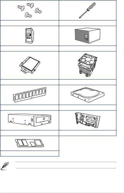
Installation tools and components
1 Bag of screws |
Phillips (cross) screwdriver |
PC chassis |
Power supply unit |
AMD SocketTR4 CPU |
AMD SocketTR4 compatible CPU Fan |
DDR4 DIMM |
SATA hard disk drive |
SATA optical disc drive (optional) |
Graphics card |
M.2 SSD module (optional) |
|
The tools and components in the table above are not included in the motherboard package.
xiii

xiv

Product Introduction |
1 |
1.1Motherboard overview
1.1.1Before you proceed
Take note of the following precautions before you install motherboard components or change any motherboard settings.
•Unplug the power cord from the wall socket before touching any component.
•Before handling components, use a grounded wrist strap or touch a safely grounded object or a metal object, such as the power supply case, to avoid damaging them due to static electricity.
•Hold components by the edges to avoid touching the ICs on them.
•Whenever you uninstall any component, place it on a grounded antistatic pad or in the bag that came with the component.
•Before you install or remove any component, ensure that the ATX power supply is switched off or the power cord is detached from the power supply. Failure to do so may cause severe damage to the motherboard, peripherals, or components.
Chapter 1
ASUS PRIME X399-A |
1-1 |
1 Chapter
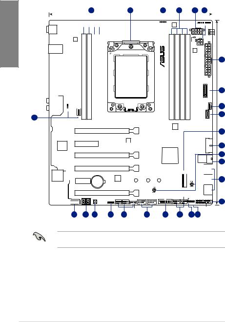
1.1.2Motherboard layout
1 |
26.9cm(10.6in) 2 |
3 |
|
1 |
4 |
5 |
|
|
|
|||||||||
|
|
|
|
|
|
|
|
|
|
|
|
|
|
|
|
|
|
|
|
|
|
|
|
|
|
|
|
|
|
CPU_OPT |
|
|
|
|
|||
|
|
|
|
|
|
|
|
|
|
|
CPU_FAN |
|||||||
|
|
|
|
|
|
|
|
|
|
|
|
|
|
|
|
|
|
|
|
|
|
|
|
|
|
|
|
|
|
|
|
|
|
|
|
|
|
|
|
|
|
RGB_HEADER2 |
DIGI+ |
|
|
|
|
|
|
|
|
|
|
|||
|
|
|
|
|
|
|
|
EPU |
|
|
|
|
|
|
|
|
|
|
|
|
|
|
|
|
|
|
|
|
|
|
|
|
|
|
|
|
|
BIOS_FLBK
DIGI+
U31G1_5~8
|
|
|
LANGuard |
|
|
|
module)pin-288(64bit,D1* |
module)pin-288(64bit,D2 |
LAN_U31G1_34 |
|
|
|
|
||||
|
|
|
|
|
|
|
|
|
|
|
|
|
|
|
|
|
|
U31G1_12 |
|
|
|
|
|
|
|
|
|
|
|
|
Intel |
|
|
|
|
|
|
|
|
|
I211AT |
|
|
|
|
|
|
|
|
|
_ |
_ |
|
|
|
|
|
|
ASM |
|
DIMM |
DIMM |
U31G2_EA2 |
|
|
|
|
3142 |
|
|
|
U31G2_EC1 |
|
|
|
|
|
|
DDR4 |
DDR4 |
|
|
|
|
|
|
|
||
|
|
|
|
|
|
|
||
AUDIO |
|
|
|
|
|
PUMP |
|
|
|
|
|
|
|
|
AIO_ |
|
|
|
|
COV_FAN |
|
|
|
|||
|
|
|
|
|
|
|
|
|
5
Super |
PCIEX4 |
|
|
I/O |
|
Crystal Sound
PCIEX1
Q_CODE
AAFP 


C1* (64bit, 288-pin module) |
C2 (64bit, 288-pin module) |
|
|
DDR4 DIMM_ |
DDR4 DIMM_ |
|
|
|
|
|
|
|
|
|
|
SocketTR4
128Mb BIOS
|
|
|
|
|
EATX12V_1 |
BOOT |
|
|
|
|
|
|
|
|
|
|
|
|
|
VGA |
|
|
|
|
|
|
CPU |
|
|
|
|
PWR1 |
|
DRAM |
|
|
|
|
EATX12V_2 |
|
|
|
|
|
|
8PIN |
DIGI+ |
|
DDR4 DIMM A2 (64bit, 288-pin module) |
DDR4 DIMM A1* (64bit, 288-pin module) |
DDR4 DIMM B2 (64bit, 288-pin module) |
DDR4 DIMM B1* (64bit, 288-pin module) |
PLUG_ |
EATXPWR |
M.2 2(SOCKET3) |
|
|
|
|
|
|
CHA FAN1 |
|
|
|
|
|
U31G2 C1 |
|
PRO
Clock
PCIEX16_1
DIGI+
EPU 


 910_U31G1
PCIEX16_2 |
AMD |
|
|
X399 |
U.2 |
|
|
|
|
M.2_1(SOCKET3) |
1 2 |
||
PCIEX16_3 |
|
|
|
SATA6G |
SATA6G |
||
CMOS Power |
|
|
|
|
|
3 4 |
|
TPU |
|
|
|
|
SATA6G |
SATA6G |
|
Lithium Cell |
|
|
|
|
|
|
|
|
2280 |
|
2260 |
2242 |
|
|
|
PCIEX16_4 |
|
|
|
|
|
SATA6G 5 |
SATA6G 6 |
|
|
|
M.2_FAN |
|
|
|
|
|
|
|
|
|
|
|
|
PWR_SW |
CHA_FAN3 CHA_FAN2 |
USB12 |
USB34 |
U31G1_1112 W_PUMP+ |
T_SENSOR |
|
|
RGB_HEADER1 |
|
|
|
|
|
|
|
|
|
|
|
|
CLRTC |
|
|
|
EXT_FAN |
|
|
|
|
PANEL |
|
|
|
|
|
|
|
|
|
4 30.5cm(12.0in)
6
5
7
6
8
9
10
11
12
18 |
17 |
16 |
3 |
5 |
15 |
8 |
5 |
14 13 |
Refer to 1.1.8 Internal connectors and 2.3.1 Rear I/O connection for more information about rear panel connectors and internal connectors.
1-2 |
Chapter 1: Product Introduction |

Layout contents
Connectors/Jumpers/Buttons and switches/Slots |
Page |
|
1. |
DDR4 DIMM slots |
1-5 |
2. |
SocketTR4 CPU socket |
1-4 |
3. |
RGB header (4-pin RGB_HEADER1-2) |
1-25 |
4. |
ATX power connectors (24-pin EATXPWR; 8-pin EATX12V_1; 4-pin |
1-22 |
|
EATX12V_2) |
|
5. |
CPU, CPU optional, cover, AIO pump, water pump+, extension, M.2, |
1-21 |
|
and chassis fan connectors (4-pin CPU_FAN; 4-pin CPU_OPT; 3-pin |
|
|
COV_FAN; 4-pin AIO_PUMP; 4-pin W_PUMP+; 4-pin M.2_FAN; 5-pin |
|
|
EXT_FAN; 4-pin CHA_FAN1-3) |
|
6. |
M.2 sockets [M.2_1(Socket 3); M.2_2(Socket 3)] |
1-24 |
7. |
USB 3.1 Gen 2 front panel connector (U31G2_C1) |
1-18 |
8. |
USB 3.1 Gen 1 connectors (20-1 pin U31G1_910; U31G1_1112) |
1-19 |
9. |
3D Mount holes |
1-10 |
10. |
U.2 connector (U.2) |
1-24 |
11. |
AMD Serial ATA 6.0 Gb/s connectors (7-pin SATA6G_1-6) |
1-17 |
12. |
System panel connector (20-5 pin PANEL) |
1-23 |
13. |
Clear RTC RAM jumper (2-pin CLRTC) |
1-9 |
14. |
Thermal sensor connector (2-pin T_SENSOR) |
1-20 |
15. |
USB 2.0 connectors (10-1 pin USB12; USB34) |
1-20 |
16. |
Power-on button |
1-10 |
17. |
Q-Code LED |
1-11 |
18. |
Front panel audio connector (10-1 pin AAFP) |
1-18 |
Chapter 1
ASUS PRIME X399-A |
1-3 |
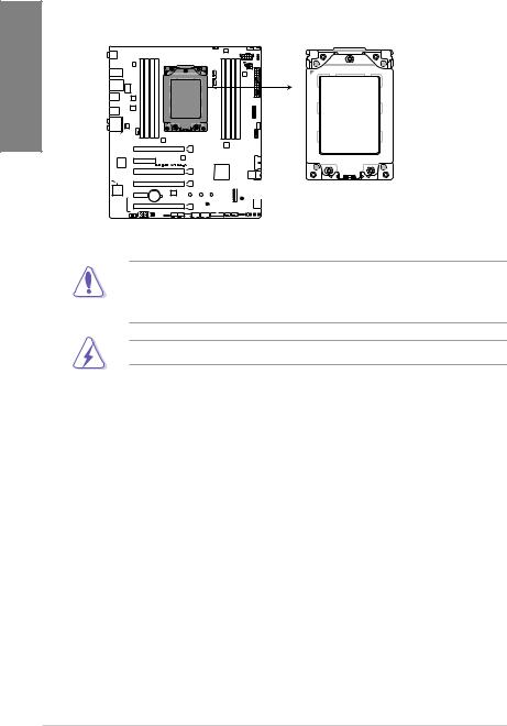
1.1.3Central Processing Unit (CPU)
The motherboard comes with a SocketTR4 socket designed for the AMD Ryzen™ Threadripper™ processors.
1 Chapter
PRIME X399-A CPU SocketTR4
The SocketTR4 socket has a different pinout design. Ensure that you use a CPU designed for the SocketTR4 socket. The CPU fits in only one correct orientation. DO NOT force the CPU into the socket to prevent bending the connectors on the socket and damaging the CPU!
Ensure that all power cables are unplugged before installing the CPU.
1-4 |
Chapter 1: Product Introduction |

1.1.4System memory
The motherboard comes with eight DDR4 (Double Data Rate 4) Dual Inline Memory Modules (DIMM) slots.
A DDR4 module is notched differently from a DDR, DDR2, or DDR3 module. DO NOT install a DDR, DDR2, or DDR3 memory module to the DDR4 slot.
|
|
|
|
|
|
|
|
|
|
|
|
|
|
|
|
|
|
|
|
|
|
DIMM D1* DIMM D2 |
|
|
|
DIMM C1* DIMM C2 |
DIMM A2 DIMM A1* |
|
|
|
DIMM B2 DIMM B1* |
|
|
|
|
|
|
|
|
|
|
|
|
|
|
|
|
|
|
|
|
|
|||||||||||
|
|
|
|
|
|
|
|
|
|
|
|
|
|
|
|
|
|
|
|
|
|||||||||||
|
|
|
|
|
|
|
|
|
|
|
|
|
|
|
|
|
|
|
|
|
|||||||||||
|
|
|
|
|
|
|
|
|
|
|
|
|
|
|
|
|
|
|
|
|
|||||||||||
|
|
|
|
|
|
|
|
|
|
|
|
|
|
|
|
|
|
|
|
|
|||||||||||
|
|
|
|
|
|
|
|
|
|
|
|
|
|
|
|
|
|
|
|
|
|
|
|
|
|
|
|
|
|
|
|
|
|
|
|
|
|
|
|
|
|
|
|
|
|
|
|
|
|
|
|
|
|
|
|
|
|
|
|
|
|
|
|
|
|
|
|
|
|
|
|
|
|
|
|
|
|
|
|
|
|
|
|
|
|
|
|
|
|
|
|
|
|
|
|
|
|
|
|
|
|
|
|
|
|
|
|
|
|
|
|
|
|
|
|
|
|
|
|
|
|
|
|
|
|
|
|
|
|
|
|
|
|
|
|
|
|
|
|
|
|
|
|
|
|
|
|
|
|
|
|
|
|
|
|
|
|
|
|
|
|
|
|
|
|
|
|
|
|
|
|
|
|
|
|
|
|
|
|
|
|
|
|
|
|
|
|
|
|
|
|
|
|
|
|
|
|
|
|
|
|
|
|
|
|
|
|
|
|
|
|
|
|
|
|
|
|
|
|
|
|
|
|
|
|
|
|
|
|
|
|
|
|
|
|
|
|
|
|
|
|
|
|
|
|
|
|
|
|
|
|
|
|
|
|
|
|
|
|
|
|
|
|
|
|
|
|
|
|
|
|
|
|
|
|
|
|
|
|
|
|
|
|
|
|
|
|
|
|
|
|
|
|
|
|
|
|
|
|
|
|
|
|
|
|
|
|
|
|
|
|
|
|
|
|
|
|
|
|
|
|
|
|
|
|
|
|
|
|
|
|
|
|
|
|
|
|
|
|
|
|
|
|
|
|
|
|
|
|
|
|
|
|
|
|
|
|
|
|
|
|
|
|
|
|
|
|
|
|
|
|
|
|
|
|
|
|
|
|
|
|
|
|
|
|
|
|
|
|
|
|
|
|
|
|
|
|
|
|
|
|
|
|
|
|
|
|
|
|
|
|
|
|
|
|
PRIME X399-A 288-pin DDR4 DIMM sockets
Recommended memory configurations
Chapter 1
ASUS PRIME X399-A |
1-5 |

1 Chapter
Memory configurations
You may install 2 GB, 4 GB, 8 GB and 16 GB unbuffered ECC and non-ECC DDR4 DIMMs into the DIMM sockets.
• You may install varying memory sizes in Channel A, Channel B, Channel C, and Channel D. The system maps the total size of the lower-sized channel for the quad channel configuration. Any excess memory from the higher-sized channel is then mapped for single-channel operation.
•This motherboard does not support DIMMs made up of 512 Mb (64 MB) chips or less (Memory chip capacity counts in Megabit, 8 Megabit/Mb = 1 Megabyte/MB).
• The default memory operation frequency is dependent on its Serial Presence Detect (SPD), which is the standard way of accessing information from a memory module. Under the default state, some memory modules for overclocking may operate at a lower frequency than the vendor-marked value.
•For system stability, use a more efficient memory cooling system to support a full memory load (8 DIMMs) or overclocking condition.
•Always install the DIMMS with the same CAS Latency. For an optimum compatibility, we recommend that you install memory modules of the same version or data code (D/C) from the same vendor. Check with the vendor to get the correct memory modules.
•Visit the ASUS website for the latest QVL.
1-6 |
Chapter 1: Product Introduction |
1.1.5Expansion slots
Unplug the power cord before adding or removing expansion cards. Failure to do so may cause you physical injury and damage motherboard components.
Chapter 1
PCIEX16_1
PCIEX4
PCIEX16_2
PCIEX16_3

 PCIEX1
PCIEX16_4
Slot No. Slot Description
1PCIe 3.0/2.0 x16_1 slot
2PCIe 2.0 x4 slot
3PCIe 3.0/2.0 x16_2 slot
4PCIe 3.0/2.0 x16_3 slot
5PCIe 2.0 x1 slot
6PCIe 3.0/2.0 x16_4 slot
ASUS PRIME X399-A |
1-7 |

1 Chapter
AMD Ryzen™ Threadripper™ Processors
VGA Configuration |
PCI Express 3.0 operating mode |
|||
Single VGA |
SLI™/CFX |
3-Way SLI™/CFX |
||
|
||||
|
|
|
|
|
PCIe x16_1 |
x16 |
x16 |
x16 |
|
|
|
|
|
|
PCIe x16_2 |
N/A |
N/A |
N/A |
|
|
|
|
|
|
PCIe x16_3 |
N/A |
x16 |
x16 |
|
|
|
|
|
|
PCIe x16_4 |
N/A |
N/A |
x8 |
|
|
|
|
|
|
•We recommend that you provide sufficient power when running CrossFireX™ or SLI™ mode.
•Connect chassis fans to the motherboard chassis fan connectors when using multiple graphics cards for better thermal environment.
1-8 |
Chapter 1: Product Introduction |

1.1.6Jumpers, buttons and holes
1. Clear RTC RAM jumper (2-pin CLRTC) |
|
|
This jumper allows you to clear the Real Time Clock (RTC) RAM in CMOS. You can |
|
|
clear the CMOS memory of date, time, and system setup parameters by erasing the |
1 |
|
CMOS RTC RAM data. The onboard button cell battery powers the RAM data in |
||
Chapter |
||
CMOS, which include system setup information such as system passwords. |
||
|
CLRTC
PIN 1
PRIME X399-A Clear RTC RAM
To erase the RTC RAM:
1.Turn OFF the computer and unplug the power cord.
2.Short-circuit pin 1-2 with a metal object or jumper cap for about 5-10 seconds.
3.Plug the power cord and turn ON the computer.
4.Hold down the <Delete> key during the boot process and enter BIOS setup to re-enter data.
Except when clearing the RTC RAM, never place a metal object or jumper cap on the
CLRTC jumper. Placing a metal object or jumper cap will cause system boot failure!
•If the steps above do not help, remove the onboard battery and place a metal object or jumper cap again to clear the CMOS RTC RAM data. After the CMOS clearance, reinstall the battery.
•You do not need to clear the RTC when the system hangs due to overclocking. For system failure due to overclocking, use the C.P.R. (CPU Parameter Recall) feature. Shut down and reboot the system so the BIOS can automatically reset parameter settings to default values.
•Due to the chipset behavior, AC power off is required to enable C.P.R. function. You must turn off and turn on the power supply or unplug and plug the power cord before rebooting the system.
ASUS PRIME X399-A |
1-9 |
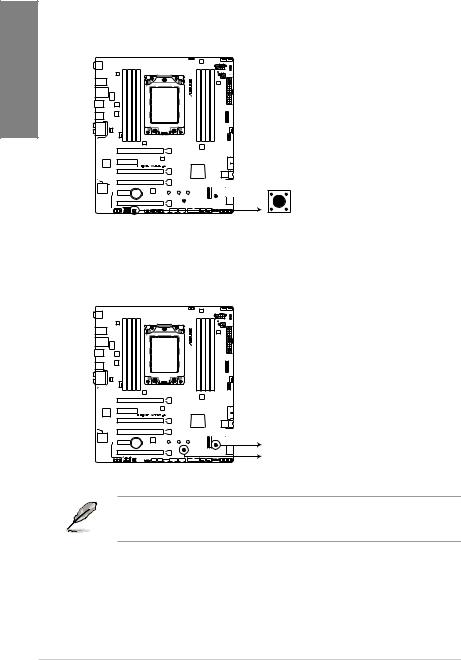
2. |
Power-on button |
|
The motherboard comes with a power-on button that allows you to power up or wake |
|
up the system. The button also lights up when the system is plugged to a power source |
1 Chapter |
indicating that you should shut down the system and unplug the power cable before |
removing or installing any motherboard component. |
|
|
PWR_SW
PRIME X399-A Power-on button
3.3D Mount holes
Secure 3D printed parts to these 3D Mount holes for a personalized motherboard.
 3D_MOUNT
 3D_MOUNT
PRIME X399-A 3D Mount holes
For more details regarding the installation of the 3D printing part on your motherboard, please refer to the product page of your motherboard on the ASUS website at http://www.asus.com.
1-10 |
Chapter 1: Product Introduction |
1.1.7Onboard LEDs
1.POST State LEDs
The POST State LEDs provide the status of these key components during POST (Power-On Self-Test): CPU, memory modules, VGA card, and hard disk drives. If an error is found, the critical component’s LED stays lit up until the problem is solved.


 BOOT (YELLOW GREEN)
 VGA (WHITE)
 CPU (RED)
 DRAM (YELLOW)
PRIME X399-A CPU/ DRAM/
BOOT_DEVICE/ VGA LED
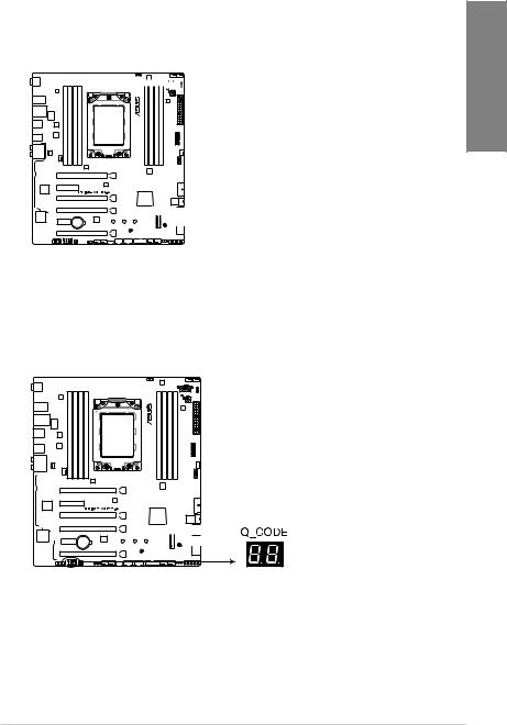
2.Q-Code LED
The Q-Code LED design provides you with a 2-digit error code that displays the system status. Refer to the Q-Code table on the next page for details.
PRIME X399-A Q-Code LEDs
Chapter 1
ASUS PRIME X399-A |
1-11 |

1 Chapter
Q-Code table
Code |
Description |
|
00 |
|
Not used |
|
|
|
01 |
|
Power on. Reset type detection (soft/hard). |
02 |
|
AP initialization before microcode loading |
|
|
|
03 |
|
System Agent initialization before microcode loading |
04 |
|
PCH initialization before microcode loading |
|
|
|
06 |
|
Microcode loading |
07 |
|
AP initialization after microcode loading |
|
|
|
08 |
|
System Agent initialization after microcode loading |
|
|
|
09 |
|
PCH initialization after microcode loading |
0B |
|
Cache initialization |
|
|
|
0C – 0D |
Reserved for future AMI SEC error codes |
|
0E |
|
Microcode not found |
0F |
|
Microcode not loaded |
|
|
|
10 |
|
PEI Core is started |
11 |
– 14 |
Pre-memory CPU initialization is started |
|
|
|
15 |
– 18 |
Pre-memory System Agent initialization is started |
19 |
– 1C |
Pre-memory PCH initialization is started |
|
|
|
2B – 2F |
Memory initialization |
|
30Reserved for ASL (see ASL Status Codes section below)
31Memory Installed
32 |
– 36 |
CPU post-memory initialization |
|
37 |
– 3A |
Post-Memory System Agent initialization is started |
|
|
|
||
3B – 3E |
Post-Memory PCH initialization is started |
||
4F |
|
DXE IPL is started |
|
|
|
|
|
50 |
– 53 |
Memory initialization error. Invalid memory type or incompatible memory |
|
speed |
|||
|
|
||
54Unspecified memory initialization error
55Memory not installed
56Invalid CPU type or Speed
57CPU mismatch
58CPU self test failed or possible CPU cache error
59CPU micro-code is not found or micro-code update is failed
(continued on the next page)
1-12 |
Chapter 1: Product Introduction |

Q-Code table
Code |
Description |
5A |
Internal CPU error |
|
|
5B |
Reset PPI is not available |
5C – 5F |
Reserved for future AMI error codes |
|
|
E0 |
S3 Resume is stared (S3 Resume PPI is called by the DXE IPL) |
E1 |
S3 Boot Script execution |
|
|
E2 |
Video repost |
E3 |
OS S3 wake vector call |
E4 – E7 |
Reserved for future AMI progress codes |
|
|
E8 |
S3 Resume Failed |
E9 |
S3 Resume PPI not Found |
|
|
EA |
S3 Resume Boot Script Error |
EB |
S3 OS Wake Error |
|
|
EC – EF |
Reserved for future AMI error codes |
F0 |
Recovery condition triggered by firmware (Auto recovery) |
F1 |
Recovery condition triggered by user (Forced recovery) |
|
|
F2 |
Recovery process started |
F3 |
Recovery firmware image is found |
|
|
F4 |
Recovery firmware image is loaded |
F5 – F7 |
Reserved for future AMI progress codes |
|
|
F8 |
Recovery PPI is not available |
F9 |
Recovery capsule is not found |
FA |
Invalid recovery capsule |
|
|
FB – FF |
Reserved for future AMI error codes |
60DXE Core is started
61NVRAM initialization
62Installation of the PCH Runtime Services
63 – 67 |
CPU DXE initialization is started |
68PCI host bridge initialization
69System Agent DXE initialization is started
|
6A |
System Agent DXE SMM initialization is started |
|
|
6B – 6F |
System Agent DXE initialization (System Agent module specific) |
|
|
|
(continued on the next page) |
|
Chapter 1
ASUS PRIME X399-A |
1-13 |

1 Chapter
Q-Code table
Code Description
70PCH DXE initialization is started
71PCH DXE SMM initialization is started
72PCH devices initialization
73– 77 PCH DXE Initialization (PCH module specific)
78ACPI module initialization
79CSM initialization
7A – 7F Reserved for future AMI DXE codes
90Boot Device Selection (BDS) phase is started
91Driver connecting is started
92PCI Bus initialization is started
93PCI Bus Hot Plug Controller Initialization
94PCI Bus Enumeration
95PCI Bus Request Resources
96PCI Bus Assign Resources
97Console Output devices connect
98Console input devices connect
99Super IO Initialization
9A |
USB initialization is started |
|
|
9B |
USB Reset |
9C |
USB Detect |
|
|
9D |
USB Enable |
9E – 9F |
Reserved for future AMI codes |
A0 |
IDE initialization is started |
|
|
A1 |
IDE Reset |
A2 |
IDE Detect |
|
|
A3 |
IDE Enable |
A4 |
SCSI initialization is started |
|
|
A5 |
SCSI Reset |
A6 |
SCSI Detect |
A7 |
SCSI Enable |
|
|
A8 |
Setup Verifying Password |
(continued on the next page)
1-14 |
Chapter 1: Product Introduction |

Q-Code table
Code |
Description |
A9 |
Start of Setup |
|
|
AA |
Reserved for ASL (see ASL Status Codes section below) |
AB |
Setup Input Wait |
|
|
AC |
Reserved for ASL (see ASL Status Codes section below) |
AD |
Ready To Boot event |
AE |
Legacy Boot event |
|
|
AF |
Exit Boot Services event |
B0 |
Runtime Set Virtual Address MAP Begin |
|
|
B1 |
Runtime Set Virtual Address MAP End |
B2 |
Legacy Option ROM Initialization |
|
|
B3 |
System Reset |
B4 |
USB hot plug |
B6 |
Clean-up of NVRAM |
|
|
B7 |
Configuration Reset (reset of NVRAM settings) |
B8– BF |
Reserved for future AMI codes |
|
|
D0 |
CPU initialization error |
D1 |
System Agent initialization error |
|
|
D2 |
PCH initialization error |
D3 |
Some of the Architectural Protocols are not available |
D4 |
PCI resource allocation error. Out of Resources |
|
|
D5 |
No Space for Legacy Option ROM |
D6 |
No Console Output Devices are found |
|
|
D7 |
No Console Input Devices are found |
D8 |
Invalid password |
|
|
D9 |
Error loading Boot Option (LoadImage returned error) |
DA |
Boot Option is failed (StartImage returned error) |
DB |
Flash update is failed |
|
|
DC |
Reset protocol is not available |
B5 |
PCI bus hot plug |
Chapter 1
ASUS PRIME X399-A |
1-15 |
Loading...