


Pro WS 621-64L |
Motherboard |
|
|
SAGE Series |
|
|
|

E15495
First Edition
June 2019
Copyright© 2019 ASUSTeK COMPUTER INC. All Rights Reserved.
No part of this manual, including the products and software described in it, may be reproduced, transmitted, transcribed, stored in a retrieval system, or translated into any language in any form or by any means, except documentation kept by the purchaser for backup purposes, without the express written permission of ASUSTeK COMPUTER INC. (“ASUS”).
Product warranty or service will not be extended if: (1) the product is repaired, modified or altered, unless such repair, modification of alteration is authorized in writing by ASUS; or (2) the serial number of the product is defaced or missing.
ASUS PROVIDES THIS MANUAL “AS IS” WITHOUT WARRANTY OF ANY KIND, EITHER EXPRESS OR IMPLIED, INCLUDING BUT NOT LIMITED TO THE IMPLIED WARRANTIES OR CONDITIONS OF MERCHANTABILITY OR FITNESS FOR A PARTICULAR PURPOSE. IN NO EVENT SHALL ASUS, ITS DIRECTORS, OFFICERS, EMPLOYEES OR AGENTS BE LIABLE FOR ANY INDIRECT, SPECIAL, INCIDENTAL, OR CONSEQUENTIAL DAMAGES (INCLUDING DAMAGES FOR LOSS OF PROFITS, LOSS OF BUSINESS, LOSS OF USE OR DATA, INTERRUPTION OF BUSINESS AND THE LIKE), EVEN IF ASUS HAS BEEN ADVISED OF THE POSSIBILITY OF SUCH DAMAGES ARISING FROM ANY DEFECT OR ERROR IN THIS MANUAL OR PRODUCT.
SPECIFICATIONS AND INFORMATION CONTAINED IN THIS MANUAL ARE FURNISHED FOR INFORMATIONAL USE ONLY, AND ARE SUBJECT TO CHANGE AT ANY TIME WITHOUT NOTICE, AND SHOULD NOT BE CONSTRUED AS A COMMITMENT BY ASUS. ASUS ASSUMES NO RESPONSIBILITY OR LIABILITY FOR ANY ERRORS OR INACCURACIES THAT MAY APPEAR IN THIS MANUAL, INCLUDING THE PRODUCTS AND SOFTWARE DESCRIBED IN IT.
Products and corporate names appearing in this manual may or may not be registered trademarks or copyrights of their respective companies, and are used only for identification or explanation and to the owners’ benefit, without intent to infringe.
Offer to Provide Source Code of Certain Software
This product contains copyrighted software that is licensed under the General Public License (“GPL”), under the Lesser General Public License Version (“LGPL”) and/or other Free Open Source Software Licenses. Such software in this product is distributed without any warranty to the extent permitted by the applicable law. Copies of these licenses are included in this product.
Where the applicable license entitles you to the source code of such software and/or other additional data, you may obtain it for a period of three years after our last shipment of the product, either
(1)for free by downloading it from https://www.asus.com/support/
or
(2)for the cost of reproduction and shipment, which is dependent on the preferred carrier and the location where you want to have it shipped to, by sending a request to:
ASUSTeK Computer Inc.
Legal Compliance Dept.
15 Li Te Rd.,
Beitou, Taipei 112
Taiwan
In your request please provide the name, model number and version, as stated in the About Box of the product for which you wish to obtain the corresponding source code and your contact details so that we can coordinate the terms and cost of shipment with you.
The source code will be distributed WITHOUT ANY WARRANTY and licensed under the same license as the corresponding binary/object code.
This offer is valid to anyone in receipt of this information.
ASUSTeK is eager to duly provide complete source code as required under various Free Open Source Software licenses. If however you encounter any problems in obtaining the full corresponding source code we would be much obliged if you give us a notification to the email address gpl@asus.com, stating the product and describing the problem (please DO NOT send large attachments such as source code archives, etc. to this email address).
ii

Contents
Safety information..................................................................................................... |
vii |
About this guide........................................................................................................ |
viii |
Pro WS C621-64L SAGE Series specifications summary........................................ |
x |
Package contents..................................................................................................... |
xiii |
Chapter 1: |
Product Introduction |
|
|
1.1 |
Before you proceed.................................................................................... |
1-1 |
|
1.2 |
Motherboard layout.................................................................................... |
1-2 |
|
1.3 |
Central Processing Unit (CPU).................................................................. |
1-4 |
|
1.4 |
System memory.......................................................................................... |
1-5 |
|
1.5 |
Expansion slots.......................................................................................... |
1-7 |
|
1.6 |
Onboard buttons......................................................................................... |
1-9 |
|
1.7 |
Onboard jumpers...................................................................................... |
1-10 |
|
1.8 |
Onboard LEDs........................................................................................... |
1-16 |
|
1.9 |
Internal connectors.................................................................................. |
1-20 |
|
Chapter 2: |
Basic Installation |
|
|
2.1 |
Building your PC system........................................................................... |
2-1 |
|
|
2.1.1 |
CPU and heatsink installation...................................................... |
2-1 |
|
2.1.2 |
Motherboard installation.............................................................. |
2-3 |
|
2.1.3 |
DIMM installation......................................................................... |
2-5 |
|
2.1.4 |
ATX power connection................................................................. |
2-6 |
|
2.1.5 |
SATA device connection.............................................................. |
2-7 |
|
2.1.6 |
Front I/O connector...................................................................... |
2-8 |
|
2.1.7 |
Expansion card installation.......................................................... |
2-9 |
|
2.1.8 |
M.2 installation........................................................................... |
2-10 |
2.2 |
BIOS update utility.................................................................................... |
2-12 |
|
2.3 |
Motherboard rear and audio connections.............................................. |
2-14 |
|
|
2.3.1 |
Rear I/O connection................................................................... |
2-14 |
|
2.3.2 |
Audio I/O connections................................................................ |
2-17 |
2.4 |
Starting up for the first time.................................................................... |
2-19 |
|
2.5 |
Turning off the computer......................................................................... |
2-19 |
|
Chapter 3: |
BIOS Setup |
|
|
3.1 |
Managing and updating your BIOS........................................................... |
3-1 |
|
|
3.1.1 |
ASUS CrashFree BIOS 3 utility................................................... |
3-1 |
|
3.1.2 |
ASUS EzFlash Utility................................................................... |
3-2 |
|
3.1.3 |
BUPDATER utility........................................................................ |
3-3 |
iii

Contents
3.2 |
BIOS setup program................................................................................... |
3-5 |
|
|
3.2.1 |
BIOS menu screen...................................................................... |
3-6 |
|
3.2.2 |
Menu bar...................................................................................... |
3-6 |
|
3.2.3 |
Menu items.................................................................................. |
3-7 |
|
3.2.4 |
Submenu items............................................................................ |
3-7 |
|
3.2.5 |
Navigation keys........................................................................... |
3-7 |
|
3.2.6 |
General help................................................................................ |
3-7 |
|
3.2.7 |
Configuration fields...................................................................... |
3-7 |
|
3.2.8 |
Pop-up window............................................................................ |
3-7 |
|
3.2.9 |
Scroll bar...................................................................................... |
3-7 |
3.3 |
Main menu................................................................................................... |
3-8 |
|
3.4 |
Ai Tweaker menu........................................................................................ |
3-8 |
|
3.5 |
Performance Tuning menu........................................................................ |
3-9 |
|
3.6 |
Advanced menu........................................................................................ |
3-10 |
|
|
3.6.1 |
Trusted Computing.................................................................... |
3-10 |
|
3.6.2 |
ACPI Settings............................................................................ |
3-10 |
|
3.6.3 |
SMART Self Test....................................................................... |
3-10 |
|
3.6.4 |
Super IO Configuration.............................................................. |
3-11 |
|
3.6.5 |
Serial Port Console Redirection................................................. |
3-11 |
|
3.6.6 |
CPU Storage Configuration....................................................... |
3-11 |
|
3.6.7 |
Onboard LAN Configuration...................................................... |
3-11 |
|
3.6.8 |
APM........................................................................................... |
3-12 |
|
3.6.9 |
PCI Subsystem Settings............................................................ |
3-12 |
|
3.6.10 |
USB Configuration..................................................................... |
3-13 |
|
3.6.11 |
CSM Configuration.................................................................... |
3-13 |
|
3.6.12 |
NVMe Configuration.................................................................. |
3-14 |
|
3.6.13 |
Offboard SATA Controller Configuration................................... |
3-14 |
|
3.6.14 |
Audio Configuration................................................................... |
3-14 |
|
3.6.15 |
ASMedia Storage Controller...................................................... |
3-14 |
|
3.6.16 |
Network Stack Configuration..................................................... |
3-14 |
|
3.6.17 |
iSCSI Configuration .................................................................. |
3-14 |
3.7 |
Platform Configuration menu.................................................................. |
3-15 |
|
|
3.7.1 |
PCH Configuration..................................................................... |
3-15 |
|
3.7.2 |
Miscellaneous Configuration...................................................... |
3-15 |
|
3.7.3 |
Workstation ME Configuration................................................... |
3-15 |
|
3.7.4 |
Runtime Error Logging............................................................... |
3-15 |
iv

Contents
3.8 |
Socket Configuration menu..................................................................... |
3-16 |
|
|
3.8.1 |
Processor Configuration............................................................ |
3-16 |
|
3.8.2 |
UPI Configuration...................................................................... |
3-16 |
|
3.8.3 |
Memory Configuration............................................................... |
3-16 |
|
3.8.4 |
IIO Configuration........................................................................ |
3-16 |
|
3.8.5 |
Advanced Power Management Configuration........................... |
3-16 |
3.9 |
Event Logs menu...................................................................................... |
3-17 |
|
|
3.9.1 |
Change Smbios Event Log Settings.......................................... |
3-17 |
|
3.9.2 |
View Smbios Event Log............................................................. |
3-17 |
3.10 |
Server Mgmt menu................................................................................... |
3-18 |
|
|
3.10.1 |
System Event Log...................................................................... |
3-18 |
|
3.10.2 |
BMC network configuration........................................................ |
3-18 |
|
3.10.3 |
View System Event Log............................................................. |
3-18 |
3.11 |
Monitor menu............................................................................................ |
3-18 |
|
3.12 |
Security menu........................................................................................... |
3-18 |
|
3.13 |
Boot menu................................................................................................. |
3-18 |
|
3.14 |
Tool menu.................................................................................................. |
3-19 |
|
3.15 |
Save & Exit menu...................................................................................... |
3-19 |
|
Chapter 4: |
RAID Support |
|
|
4.1 |
RAID configurations................................................................................... |
4-1 |
|
|
4.1.1 |
RAID definitions........................................................................... |
4-1 |
|
4.1.2 |
Installing Serial ATA hard disks................................................... |
4-2 |
|
4.1.3 |
Setting the RAID item in BIOS..................................................... |
4-2 |
|
4.1.4 |
RAID configuration utilities........................................................... |
4-2 |
4.2Intel® Rapid Storage Technology enterprise SATA Option
|
ROM Utility.................................................................................................. |
4-3 |
|
|
4.2.1 |
Creating a RAID set..................................................................... |
4-4 |
|
4.2.2 |
Deleting a RAID set..................................................................... |
4-6 |
|
4.2.3 |
Resetting disks to Non-RAID....................................................... |
4-7 |
|
4.2.4 |
Exiting the Intel® Rapid Storage Technology enterprise |
|
|
|
SATA Option ROM utility............................................................. |
4-7 |
|
4.2.5 |
Rebuilding the RAID.................................................................... |
4-8 |
|
4.2.6 |
Setting the Boot array in the BIOS Setup Utility........................ |
4-10 |
4.3 |
Intel® Rapid Storage Technology enterprise (Windows)...................... |
4-11 |
|
|
4.3.1 |
Creating a RAID set................................................................... |
4-12 |
|
4.3.2 |
Changing a Volume Type.......................................................... |
4-14 |
|
4.3.3 |
Deleting a volume...................................................................... |
4-15 |
|
4.3.4 |
Preferences............................................................................... |
4-16 |
v

Contents
4.4 |
Intel® Virtual Raid on CPU in BIOS.......................................................... |
4-17 |
|
|
4.4.1 |
Creating a RAID set................................................................... |
4-18 |
|
4.4.2 |
Deleting a RAID set................................................................... |
4-20 |
4.4.3Installing the RAID controller driver during Windows® 10 OS
|
|
installation .................................................................................. |
4-21 |
Chapter 5: |
Multi GPU Support |
|
|
5.1 |
AMD CrossFireX™ technology.................................................................. |
5-1 |
|
|
5.1.1 |
Requirements .............................................................................. |
5-1 |
|
5.1.2 |
Before you begin .......................................................................... |
5-1 |
|
5.1.3 |
Installing two CrossFireX™ graphics cards ................................. |
5-2 |
|
5.1.4 |
Installing three CrossFireX™ graphics cards .............................. |
5-3 |
|
5.1.5 |
Installing four CrossFireX™ graphics cards ................................ |
5-4 |
|
5.1.6 |
Installing the device drivers ......................................................... |
5-5 |
|
5.1.7 |
Enabling the AMD CrossFireX™ technology ............................... |
5-5 |
5.2 |
NVIDIA® SLI® technology........................................................................... |
5-7 |
|
|
5.2.1 |
Requirements .............................................................................. |
5-7 |
|
5.2.2 |
Installing two SLI - ready graphics cards ....................................... |
5-7 |
|
5.2.3 |
Installing three SLI - ready graphics cards .................................... |
5-8 |
|
5.2.4 |
Installing four SLI - ready graphics cards ...................................... |
5-9 |
|
5.2.5 |
Installing the device drivers ....................................................... |
5-10 |
|
5.2.6 |
Enabling the NVIDIA ® SLI ® technology ...................................... |
5-10 |
Appendix |
|
|
|
Pro WS C621 64L SAGE block diagram................................................................. |
A-1 |
||
Pro WS C621 64L SAGE/10G block diagram......................................................... |
A-2 |
||
Q-Code table |
............................................................................................................. |
A-3 |
|
Notices |
..................................................................................................................... |
|
A-6 |
ASUS contact ....................................................................................information |
A-10 |
||
vi

Safety information
Electrical safety
•To prevent electrical shock hazard, disconnect the power cable from the electrical outlet before relocating the system.
•When adding or removing devices to or from the system, ensure that the power cables for the devices are unplugged before the signal cables are connected. If possible, disconnect all power cables from the existing system before you add a device.
•Before connecting or removing signal cables from the motherboard, ensure that all power cables are unplugged.
•Seek professional assistance before using an adapter or extension cord. These devices could interrupt the grounding circuit.
•Ensure that your power supply is set to the correct voltage in your area. If you are not sure about the voltage of the electrical outlet you are using, contact your local power company.
•If the power supply is broken, do not try to fix it by yourself. Contact a qualified service technician or your retailer.
Operation safety
•Before installing the motherboard and adding devices on it, carefully read all the manuals that came with the package.
•Before using the product, ensure all cables are correctly connected and the power cables are not damaged. If you detect any damage, contact your dealer immediately.
•To avoid short circuits, keep paper clips, screws, and staples away from connectors, slots, sockets and circuitry.
•Avoid dust, humidity, and temperature extremes. Do not place the product in any area where it may become wet.
•Place the product on a stable surface.
•If you encounter technical problems with the product, contact a qualified service technician or your retailer.
vii

About this guide
This user guide contains the information you need when installing and configuring the motherboard.
How this guide is organized
This guide contains the following parts:
1.Chapter 1: Product Introduction
This chapter describes the features of the motherboard and the new technology it supports. It includes description of the switches, jumpers, and connectors on the motherboard.
2.Chapter 2: Basic Installation
This chapter lists the hardware setup procedures that you have to perform when installing system components.
3.Chapter 3: BIOS Setup
This chapter tells how to change system settings through the BIOS Setup menus. Detailed descriptions of the BIOS parameters are also provided.
4.Chapter 4: RAID Support
This chapter describes the RAID configurations.
5.Chapter 5: Multi GPU Support
This chapter describes how to install and configure multiple AMD CrossFire™ graphics cards.
Where to find more information
Refer to the following sources for additional information and for product and software updates.
1.ASUS website
The ASUS website (www.asus.com) provides updated information on ASUS hardware and software products.
2.Optional documentation
Your product package may include optional documentation, such as warranty flyers, that may have been added by your dealer. These documents are not part of the standard package.
viii

Conventions used in this guide
To ensure that you perform certain tasks properly, take note of the following symbols used throughout this manual.
DANGER/WARNING: Information to prevent injury to yourself when trying to complete a task.
CAUTION: Information to prevent damage to the components when trying to complete a task.
IMPORTANT: Instructions that you MUST follow to complete a task.
NOTE: Tips and additional information to help you complete a task.
Typography
Bold text |
Indicates a menu or an item to select. |
Italics |
Used to emphasize a word or a phrase. |
<Key> |
Keys enclosed in the less-than and greater-than sign |
|
means that you must press the enclosed key. |
|
Example: <Enter> means that you must press the Enter |
|
or Return key. |
<Key1> + <Key2> + <Key3> |
If you must press two or more keys simultaneously, the |
|
key names are linked with a plus sign (+). |
ix

Pro WS C621-64L SAGE Series specifications summary
Model Name |
Pro WS C621-64L SAGE |
Pro WS C621-64L SAGE/10G |
|
|
|
|
|
|
1 x Socket-P (LGA-3647) |
|
|
CPU |
Intel® Xeon W-3200 Processor Family (up to 205W) |
||
Intel® Xeon Processor Scalable Family (up to 205W) |
|||
|
* Refer to www.asus.com for Intel® CPU support list |
||
Chipset |
Intel® C621 PCH |
|
|
|
12 x DIMM (6-channel), Max. 1,536GB |
||
Memory |
DDR4 2933/2666 RDIMM/LR-DIMM/LR-DIMM 3DS |
||
* Maximum memory capacity support depends on CPU type |
|||
|
|||
|
** Refer to www.asus.com for the Memory QVL (Qualified Vendors Lists). |
||
|
|
|
|
|
Intel Xeon W-3200 Processor: |
|
|
|
PCIe x16_1 Slot (Gen3 x16 link) |
|
|
|
PCIe x16_2 Slot (Gen3 x16 link) |
|
|
|
PCIe x4_1 Slot (Gen3 x4 link) |
|
|
|
PCIe x16_3 Slot (Gen3 x16 link) |
|
|
|
PCIe x16_4 Slot (Gen3 x16 link) |
|
|
Expansion slots |
|
|
|
|
Intel Xeon Scalable Processor: |
|
|
|
PCIe x16_1 Slot (Gen3 x16 link) |
|
|
|
PCIe x16_2 Slot (Gen3 x16/x8 link) |
|
|
|
PCIe x4_1 Slot (Gen3 x4 link) |
|
|
|
PCIe x16_3 Slot (Gen3 x16 link) |
|
|
|
PCIe x16_4 Slot (Gen3 x0/x8 link) |
|
|
|
|
|
|
VGA |
- |
1 x BMC Integrated VGA header |
|
|
(Aspeed AST2500) |
||
|
|
||
|
|
|
|
|
Supports NVIDIA® 4-way SLI Technology |
||
Multi-GPU support |
Supports AMD 4-way CrossFireX Technology |
||
|
|
||
|
* Actual numbers of Multi-graphic supported differs per Vendors’ Graphic |
||
|
cards. Please check with Vendor beforehand. |
||
|
|
|
|
|
ASMedia® ASM1062R |
|
|
|
- 2 x SATA 6Gbps ports |
|
|
|
Intel® C621 PCH with Intel® RSTe (for windows only, support |
||
Storage |
software RAID 0,1,5,10) |
|
|
- 8 x SATA 6Gbps ports |
|
||
|
|
||
|
- 1 x M.2 Connector, up to 22110 (PCIe 3.0 x4 or SATA mode)* |
||
|
* The M.2 socket shares bandwidth with PCIEX4_1 when using M.2 PCIe |
||
|
mode device. |
|
|
|
(continued on the next page) |
|
|
x
Pro WS C621-64L SAGE Series specifications summary
Model Name |
Pro WS C621-64L SAGE |
Pro WS C621-64L SAGE/10G |
|
|
|
|
|
LAN |
2 x Intel® I210 Gigabit LAN |
1 x Dual port Intel® X550 10GbE |
|
Controllers |
LAN Controllers |
||
|
|||
|
|
|
|
|
ASMedia® ASM3142 |
ASMedia® ASM3142 |
|
|
- 3 x USB 3.2 Gen2 ports |
- 2 x USB 3.2 Gen2 ports |
|
|
(2 ports at rear, 1 port at |
(2 ports at rear) |
|
|
mid-board) |
Intel® C621 PCH |
|
USB |
Intel® C621 PCH |
- 6 x USB 3.2 Gen1 ports |
|
- 6 x USB 3.2 Gen1 ports |
|||
|
(4 ports at rear, 2 ports at |
||
|
(4 ports at rear, 2 ports at |
mid-board) |
|
|
mid-board) |
- 2 x USB 2.0 port |
|
|
|
||
|
- 2 x USB 2.0 port |
(2 ports at mid-board) |
|
|
(2 ports at mid-board) |
|
|
|
|
|
|
|
Realtek® ALC1220A 7.1-channel HD Audio CODEC |
||
|
- Impedance sense for front and rear headphone outputs |
||
Audio |
- Jack-detection, Multi-streaming, Front Panel Jack-retasking |
||
|
- Optical S/PDIF output |
|
|
|
- Premium Japan-made Audio Capacitor |
||
|
|
|
|
|
- ECC memory prevents system |
- ECC memory prevents system |
|
Workstation Unique |
crash caused by memory error |
crash caused by memory error |
|
Features |
|
- Out-of-band remote |
|
|
|
management by ASMB9 |
|
|
|
|
|
|
2 x USB 3.2 Gen 2 ports |
2 x USB 3.2 Gen 2 ports |
|
|
(1 x Type-A, 1 x Type-C™) |
(1 x Type-A, 1 x Type-C™) |
|
Rear Panel I/O Ports |
4 x USB 3.2 Gen 1 ports |
4 x USB 3.2 Gen 1 ports |
|
2 x Gigabit LAN ports (RJ45) |
2 x 10GbE LAN ports (RJ45) |
||
|
|||
|
5 x Audio Jacks |
5 x Audio Jacks |
|
|
1 x Optical S/PDIF output |
1 x Optical S/PDIF output |
|
|
|
|
|
(continued on the next page)
xi

Pro WS C621-64L SAGE Series specifications summary
Model Name |
Pro WS C621-64L SAGE |
Pro WS C621-64L SAGE/10G |
|
|
|
|
|
|
1 x USB 3.2 Gen 2 connector |
1 x USB 3.2 Gen 1 connector |
|
|
support additional 1 external |
support additional 2 external |
|
|
port |
ports |
|
|
1 x USB 3.2 Gen 1 connector |
1 x USB 2.0 connector support |
|
|
support additional 2 external |
additional 2 external ports |
|
|
ports |
10 x SATA 6Gbps connectors |
|
|
1 x USB 2.0 connector support |
||
|
1 x M.2 connector, up to 22110 |
||
|
additional 2 external ports |
||
|
(PCIe 3.0 x4 or SATA mode) |
||
|
10 x SATA 6Gbps connectors |
||
|
2 x CPU Fan connectors (4-pin) |
||
|
1 x M.2 connector, up to 22110 |
||
|
8 x Chassis Fan Connectors |
||
|
(PCIe 3.0 x4 or SATA mode) |
||
|
(4-pin) |
||
|
2 x CPU Fan connectors (4-pin) |
||
|
1 x VGA connector (16-1 pin) |
||
|
8 x Chassis Fan Connectors |
||
Internal I/O Ports |
1 x TPM connector (14-1 pin) |
||
(4-pin) |
|||
1 x COM connector |
|||
|
1 x TPM connector (14-1 pin) |
||
|
1 x VROC key connector |
||
|
1 x COM connector |
||
|
1 x Front Panel Audio connector |
||
|
1 x VROC key connector |
||
|
(AAFP) |
||
|
1 x Front Panel Audio connector |
||
|
1 x 24-pin EATX power |
||
|
(AAFP) |
||
|
connector |
||
|
1 x 24-pin EATX power |
||
|
2 x 8-pin EATX 12V power |
||
|
connector |
||
|
connectors |
||
|
2 x 8-pin EATX 12V power |
||
|
1 x System Panel connector |
||
|
connectors |
||
|
1 x Chassis Intrution connector |
||
|
1 x System Panel connector |
||
|
(2-pin) |
||
|
1 x Chassis Intrution connector |
||
|
|
||
|
(2-pin)" |
|
|
|
|
|
|
BIOS Features |
256 Mb Flash ROM, UEFI BIOS, PnP, ASUS EZ Flash, ASUS |
||
CrashFree Technology |
|
||
|
|
||
|
|
|
|
|
WOL by PME, PXE |
WOL by PME, PXE |
|
Manageability |
ASUS Control Center |
ASUS Control Center |
|
|
|
ASMB9-iKVM (on-board) |
|
|
|
|
|
Operating System |
Windows® 10 64-bit |
|
|
Form Factor |
CEB Form Factor, 12” x 10.9” |
|
|
|
|
|
|
• Specifications are subject to change without notice.
• Visit the ASUS website for the software manual.
xii

Package contents
Check your motherboard package for the following items.
Motherboard |
1 x Pro WS C621-64L SAGE Series motherboard |
|
|
|
10 x Serial ATA 6Gb/s cables |
Cables |
1 x COM port flat cable |
|
1 x VGA port flat cable (for Pro WS C621-64L SAGE/10G) |
|
|
|
1 x M.2 screws kit |
Accessories |
1 x CPU Carrier |
|
1 X I/O Shield |
|
|
Application DVD |
1 x Motherboard support DVD |
|
|
Documentation |
1 x User manual |
|
|
If any of the above items is damaged or missing, contact your retailer.
xiii

xiv

Product Introduction |
1 |
1.1Before you proceed
Take note of the following precautions before you install motherboard components or change any motherboard settings.
•Unplug the power cord from the wall socket before touching any component.
•Before handling components, use a grounded wrist strap or touch a safely grounded object or a metal object, such as the power supply case, to avoid damaging them due to static electricity.
•Hold components by the edges to avoid touching the ICs on them.
•Whenever you uninstall any component, place it on a grounded antistatic pad or in the bag that came with the component.
•Before you install or remove any component, ensure that the ATX power supply is switched off or the power cord is detached from the power supply. Failure to do so may cause severe damage to the motherboard, peripherals, or components.
Chapter 1
ASUS Pro WS C621-64L SAGE Series |
1-1 |

1.2Motherboard layout
1 Chapter
•Refer to Internal connectors and Rear I/O connection for more information about rear panel connectors and internal connectors.
•The components on the motherboard may differ between models, some components may only be available for Pro WS C621-64L SAGE/10G.
1-2 |
Chapter 1: Product Introduction |

Layout contents |
Page |
|
1. |
DIMM slots |
1-5 |
2. |
Fan connector |
1-27 |
3. |
CPU socket |
1-4 |
4. |
Power connectors |
1-30 |
5. |
PMBus 1.2 PSU Select jumper |
1-12 |
6. |
Storage Add-on Card LED connector |
1-22 |
7. |
ME Firmware Force Recovery jumper |
1-12 |
8. |
DDR4 Thermal Event jumper |
1-11 |
9. |
Power Supply SMBus connector |
1-26 |
|
|
|
10. |
Serial General Purpose Input/Output connector |
1-32 |
|
|
|
11. |
System Management Bus connector |
1-31 |
12. |
USB 3.2 Gen 1 connector |
1-25 |
13. |
SATA 6Gb/s connector |
1-20 |
14. |
ASMedia® SATA 6 Gb/s connector |
1-21 |
15. |
VROC Key connector |
1-24 |
16. |
USB 3.2 Gen 2 connector (Pro WS C621-64L SAGE only) |
1-25 |
17. |
SATADOM Power jumper |
1-11 |
18. |
System Panel connector |
1-28 |
19. |
Auxiliary Panel connector (Pro WS C621-64L SAGE/10G only) |
1-29 |
20. |
USB 2.0 connector |
1-26 |
21. |
PCH_MFG1 jumper |
1-13 |
22. |
Clear RTC RAM jumper |
1-10 |
23. |
TPM connector |
1-22 |
24. |
Serial Port connector |
1-24 |
25. |
VPP_I2C1 connector (Pro WS C621-64L SAGE/10G only) |
1-31 |
26. |
Q-Code LED |
1-19 |
27. |
Reset button |
1-9 |
28. |
Power button |
1-9 |
29. |
VGA connector (Pro WS C621-64L SAGE/10G only) |
1-23 |
30. |
IPMI SW jumper (Pro WS C621-64L SAGE/10G only) |
1-13 |
31. |
Front Panel Audio connector |
1-21 |
32. |
VGA Controller jumper (Pro WS C621-64L SAGE/10G only) |
1-14 |
33. |
Baseboard Management Controller setting |
1-15 |
|
(Pro WS C621-64L SAGE/10G only) |
|
34. |
M.2 slot |
1-23 |
35. |
MicroSD card slot (Pro WS C621-64L SAGE/10G only) |
1-32 |
Chapter 1
ASUS Pro WS C621-64L SAGE Series |
1-3 |
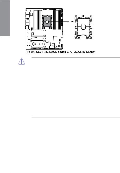
1.3Central Processing Unit (CPU)
This motherboard comes with a surface mount LGA 3647 socket designed for the Intel® Xeon W-3200 Processor Family Processors.
1 Chapter
•
•
•
•
•
•
Ensure that you install the correct CPU designed for LGA3647 socket only. DO NOT install a CPU designed for other sockets on the LGA3647 socket.
The CPU fits in only one correct orientation. DO NOT force the CPU into the socket to prevent bending the connectors on the socket and damaging the CPU.
Ensure that all power cables are unplugged before installing the CPU.
Upon purchase of the motherboard, ensure that the PnP cap is on the socket and the socket contacts are not bent. Contact your retailer immediately if the PnP cap is missing, or if you see any damage to the PnP cap/socket contacts/motherboard components. ASUS will shoulder the cost of repair only if the damage is shipment/ transit-related.
Keep the cap after installing the motherboard. ASUS will process Return Merchandise Authorization (RMA) requests only if the motherboard comes with the cap on the LGA3647 socket.
The product warranty does not cover damage to the socket contacts resulting from incorrect CPU installation/removal, or misplacement/loss/incorrect removal of the PnP cap.
1-4 |
Chapter 1: Product Introduction |
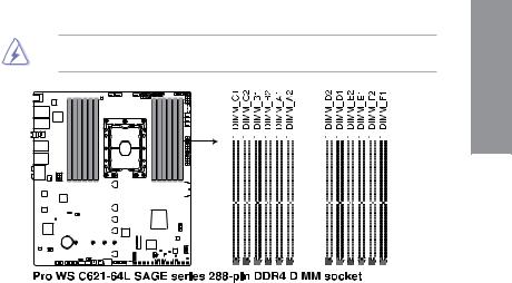
1.4System memory
The motherboard comes with twelve (12) Dual Inline Memory Modules (DIMM) slots designed for DDR4 (Double Data Rate 4) memory modules.
A DDR4 memory module is notched differently from a DDR, DDR2, or DDR3 module. DO NOT install a DDR, DDR2, or DDR3 memory module to the DDR4 slot.
Chapter 1
|
|
|
|
|
|
|
|
|
|
|
|
|
|
|
|
|
|
|
|
|
|
|
|
|
|
|
|
|
|
|
|
|
|
|
|
|
|
|
|
|
|
|
|
|
|
|
|
|
|
|
|
|
|
|
|
|
|
|
|
|
|
|
|
|
|
|
|
|
|
|
|
|
|
|
|
|
|
|
|
|
|
|
|
|
|
|
|
|
|
|
|
|
|
|
|
|
|
|
|
|
|
|
|
|
|
|
|
|
|
|
|
|
|
|
|
|
|
|
|
|
|
|
|
|
|
|
|
|
|
|
|
|
|
|
|
|
|
|
|
|
|
|
|
|
|
|
|
|
|
|
|
|
|
|
|
|
|
|
|
|
|
|
|
|
|
|
|
|
|
|
|
|
|
|
|
|
|
|
|
|
|
|
|
|
|
|
|
|
|
|
|
|
|
|
|
|
|
|
|
|
|
|
|
|
|
|
|
|
|
|
|
|
|
|
|
|
|
|
|
|
|
|
|
|
|
|
|
|
|
|
|
|
|
|
|
|
|
|
|
|
|
|
|
|
|
|
|
|
|
|
|
|
|
|
|
|
|
|
|
|
|
|
|
|
|
|
|
|
|
|
|
|
|
|
|
|
|
|
|
|
|
|
|
|
|
|
|
|
|
|
|
|
|
|
|
|
|
|
|
|
|
|
|
|
|
|
|
|
|
|
|
|
|
|
|
|
|
|
|
|
|
|
|
|
|
|
|
|
|
|
|
|
|
|
|
|
|
|
|
|
|
|
|
|
|
|
|
|
|
|
|
|
|
|
|
|
|
|
|
|
|
|
|
|
|
|
|
|
|
|
|
|
|
|
|
|
|
|
|
|
|
|
|
|
|
|
|
|
|
|
|
|
|
|
|
|
|
|
|
|
|
|
|
|
|
|
|
|
|
|
|
|
|
|
|
|
|
|
|
|
|
|
|
|
|
|
|
|
|
|
|
|
|
|
|
|
|
|
|
|
|
|
|
|
|
|
|
|
|
|
|
|
|
|
|
|
|
|
|
|
|
|
|
|
|
|
|
|
|
|
|
|
|
|
|
|
|
|
|
|
|
|
|
|
|
|
|
|
|
|
|
|
|
|
|
|
|
|
|
|
|
|
|
|
|
|
|
|
|
|
|
|
|
|
|
|
|
|
|
|
|
|
|
|
|
|
|
|
|
|
|
|
|
|
|
|
|
|
|
|
|
|
|
|
|
|
|
|
|
|
|
|
|
|
|
|
|
|
|
|
|
|
|
|
|
|
|
|
|
|
|
|
|
|
|
|
|
|
|
|
|
|
|
|
|
|
|
|
|
|
|
|
|
|
|
|
|
|
|
|
|
|
|
|
|
|
|
|
|
|
|
|
|
|
|
|
|
|
|
|
|
|
|
|
|
|
|
|
|
|
|
|
|
|
|
|
|
|
|
ASUS Pro WS C621-64L SAGE Series |
1-5 |
||||||||||||||||||||||||||||||||||||||
1 Chapter
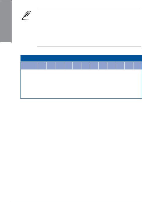
Memory configurations
You may install 16 GB and 32 GB RDIMMs; 32 GB, and 64 GB LRDIMMs; and 64GB, and 128GB LRDIMM 3DS into the DIMM sockets.
• For system stability, use a more efficient memory cooling system to support a full memory load (12 DIMMs) or overclocking condition.
•Always install the DIMMS with the same CAS Latency. For an optimum compatibility, we recommend that you install memory modules of the same version or data code (D/C) from the same vendor. Check with the vendor to get the correct memory modules.
•The DIMMs are purchased separately.
•Visit the ASUS website for the latest QVL.
Recommended memory configuration
|
C1 |
C2 |
B1 |
B2 |
A1 |
A2 |
D2 |
D1 |
E2 |
E1 |
F2 |
F1 |
|
|
|
|
|
|
|
|
|
|
|
|
|
1 DIMMs |
- |
- |
- |
- |
P |
- |
- |
- |
- |
- |
- |
- |
|
|
|
|
|
|
|
|
|
|
|
|
|
2 DIMMs |
- |
- |
- |
- |
P |
- |
- |
P |
- |
- |
- |
- |
|
|
|
|
|
|
|
|
|
|
|
|
|
4 DIMMs |
- |
- |
P |
- |
P |
- |
- |
P |
- |
P |
- |
- |
|
|
|
|
|
|
|
|
|
|
|
|
|
6 DIMMs |
P |
- |
P |
- |
P |
- |
- |
P |
- |
P |
- |
P |
|
|
|
|
|
|
|
|
|
|
|
|
|
12 DIMMs |
P |
P |
P |
P |
P |
P |
P |
P |
P |
P |
P |
P |
|
|
|
|
|
|
|
|
|
|
|
|
|
1-6 |
Chapter 1: Product Introduction |
1.5Expansion slots
Unplug the power cord before adding or removing expansion cards. Failure to do so may cause you physical injury and damage motherboard components.
Chapter 1
Slot No. Slot Description
1PCIe x16_1 slot
2PCIe x16_2 slot
3PCIe x4_1 slot 4 PCIe x16_3 slot
5PCIe x16_4 slot
ASUS Pro WS C621-64L SAGE Series |
1-7 |

1 Chapter
Recommended VGA configuration
Slot Description |
Single |
2-way |
3-way |
4-way GPU |
4-way GPU |
|
GPU |
GPU |
GPU |
(Xeon W-3200) |
(Xeon Scalable) |
||
|
||||||
PCIE 3.0 x16_1 |
x16 |
x16 |
x16 |
x16 |
x16 |
|
|
|
|
|
|
|
|
PCIE 3.0 x16_2 |
- |
- |
x16 |
x16 |
x8 |
|
|
|
|
|
|
|
|
PCIE 3.0 x4_1 |
- |
- |
- |
- |
- |
|
|
|
|
|
|
|
|
PCIE 3.0 x16_3 |
- |
x16 |
x16 |
x16 |
x16 |
|
|
|
|
|
|
|
|
PCIE 3.0 x16_4 |
- |
- |
- |
x16 |
x8 |
|
|
|
|
|
|
|
We recommend that you provide sufficient power when running CrossFireX™ or SLI® mode.
1-8 |
Chapter 1: Product Introduction |

1.6Onboard buttons
1. |
Power button |
|
|
Press the Power button to power up the system, or put the system into sleep or soft- |
1 |
|
off mode (depending on the operating system settings). |
|
|
|
Chapter |
The button also lights up when the system is plugged to a power source, indicating that you should shut down the system and unplug the power cable before removing or installing any motherboard component.
2.Reset button
Press the Reset button to reboot the system.
|
|
|
|
|
|
|
|
|
|
|
|
|
|
|
|
|
|
|
|
|
|
|
|
|
|
|
|
|
|
|
|
|
|
|
|
|
|
|
|
|
|
|
|
|
|
|
|
|
|
|
|
|
|
|
|
|
|
|
|
|
|
|
|
|
|
|
|
|
|
|
|
|
|
|
|
|
|
|
|
|
|
|
|
|
|
|
|
|
|
|
|
|
|
|
|
|
|
|
|
|
|
|
|
|
|
|
|
|
|
|
|
|
|
|
|
|
|
|
|
|
|
|
|
|
|
|
|
|
|
|
|
|
|
|
|
|
|
|
|
|
|
|
|
|
|
|
|
|
|
|
|
|
|
|
|
|
|
|
|
|
|
|
|
|
|
|
|
|
|
|
|
|
|
|
|
|
|
|
|
|
|
|
|
|
|
|
|
|
|
|
|
|
|
|
|
|
|
|
|
|
|
|
|
|
|
|
|
|
|
|
|
|
|
|
|
|
|
|
|
|
|
|
|
|
|
|
|
|
|
|
|
|
|
|
|
|
|
|
|
|
|
|
|
|
|
|
|
|
|
|
|
|
|
|
|
|
|
|
|
|
|
|
|
|
|
|
|
|
|
|
|
|
|
|
|
|
|
|
|
|
|
|
|
|
|
|
|
|
|
|
|
|
|
|
|
|
|
|
|
|
|
|
|
|
|
|
|
|
|
|
|
|
|
|
|
|
|
|
|
|
|
|
|
|
|
|
|
|
|
|
|
|
|
|
|
|
|
|
|
|
|
|
|
|
|
|
|
|
|
|
|
|
|
|
|
|
|
|
|
|
|
|
|
|
|
|
|
|
|
|
|
|
|
|
|
|
|
|
|
|
|
|
|
|
|
|
|
|
|
|
|
|
|
|
|
|
|
|
|
|
|
|
|
|
|
|
|
|
|
|
|
|
|
|
|
|
|
|
|
|
|
|
|
|
|
|
|
|
|
|
|
|
|
|
|
|
|
|
|
|
|
|
|
|
|
|
|
|
|
|
|
|
|
|
|
|
|
|
|
|
|
|
|
|
|
|
|
|
|
|
|
|
|
|
|
|
|
|
|
|
|
|
|
|
|
|
|
|
|
|
|
|
|
|
|
|
|
|
|
|
|
|
|
|
|
|
|
|
|
|
|
|
|
|
|
|
|
|
|
|
|
|
|
|
|
|
|
|
|
|
|
|
|
|
|
|
|
|
|
|
|
|
|
|
|
|
|
|
|
|
|
|
|
|
|
|
|
|
|
|
|
|
|
|
|
|
|
|
|
|
|
|
|
|
|
|
|
|
|
|
|
|
|
|
|
|
|
|
|
|
|
|
|
|
|
|
|
|
|
|
|
|
|
|
|
|
|
|
|
|
|
|
|
|
|
|
|
|
|
|
|
|
|
|
|
|
|
|
|
|
|
|
|
|
|
|
|
|
|
|
|
|
|
|
|
|
|
|
|
|
|
|
|
|
|
|
|
|
|
|
|
|
|
|
|
|
|
|
|
|
|
|
|
|
|
|
|
|
|
|
|
|
|
|
|
|
|
|
|
|
|
|
|
|
|
|
|
|
|
|
|
|
|
|
|
|
|
|
|
|
|
|
|
|
|
|
|
|
|
|
|
|
|
|
|
|
|
|
|
|
|
|
|
|
|
|
|
|
|
|
|
|
|
|
|
|
|
|
|
|
|
|
|
|
|
|
|
|
|
|
|
|
|
|
|
|
|
|
|
|
|
|
|
|
|
|
|
|
|
|
|
ASUS Pro WS C621-64L SAGE Series |
1-9 |
||||||||||||||||||||||||||||||||
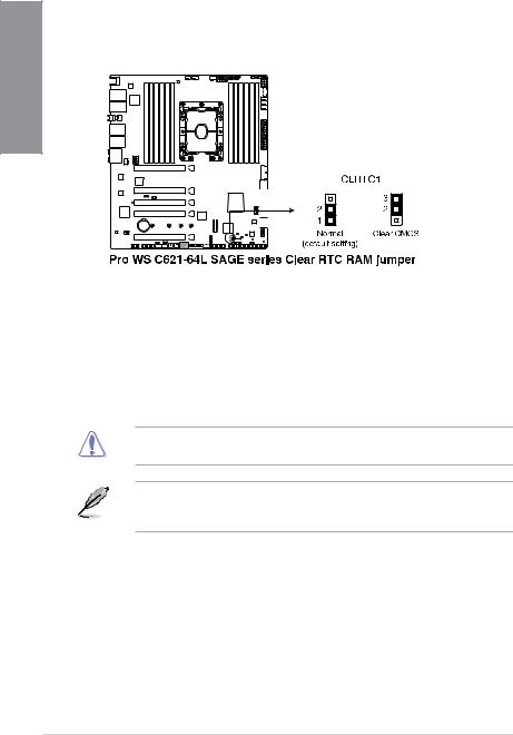
1.7Onboard jumpers
|
1. Clear RTC RAM jumper |
|
1Chapter |
The Clear RTC RAM jumper allows you to clear the Real Time Clock (RTC) RAM |
|
in the CMOS, which contains the date, time, system passwords, and system setup |
||
parameters. |
||
|
To erase the RTC RAM:
1.Turn OFF the computer and unplug the power cord.
2.Move the jumper cap from the default pins 1-2 to pins 2-3. Keep the cap on pins 2-3 for about 5 to 10 seconds, then move the cap back to pins 1-2.
3.Plug the power cord and turn ON the computer.
4.Hold down the <Del> key during the boot process and enter BIOS setup to re-enter data.
DO NOT short-circuit the pins except when clearing the RTC RAM. Short-circuiting or placing a jumper cap will cause system boot failure!
If the steps above do not help, remove the onboard button cell battery and move the jumper again to clear the CMOS RTC RAM data. After clearing the CMOS, reinstall the button cell battery.
1-10 |
Chapter 1: Product Introduction |

2.DDR4 Thermal Event jumper
Set to pins 1-2 to enable DDR4 DIMM thermal sensing event.
Chapter 1
3.SATADOM Power jumper
Set to pins 2-3 to enable SATA8 port to support SATADOM devices.
|
|
|
|
|
|
|
|
|
|
|
|
|
|
|
|
|
|
|
|
|
|
|
|
|
|
|
|
|
|
|
|
|
|
|
|
|
|
|
|
|
|
|
|
|
|
|
|
|
|
|
|
|
|
|
|
|
|
|
|
|
|
|
|
|
|
|
|
|
|
|
|
|
|
|
|
|
|
|
|
|
|
|
|
|
|
|
|
|
|
|
|
|
|
|
|
|
|
|
|
|
|
|
|
|
|
|
|
|
|
|
|
|
|
|
|
|
|
|
|
|
|
|
|
|
|
|
|
|
|
|
|
|
|
|
|
|
|
|
|
|
|
|
|
|
|
|
|
|
|
|
|
|
|
|
|
|
|
|
|
|
|
|
|
|
|
|
|
|
|
|
|
|
|
|
|
|
|
|
|
|
|
|
|
|
|
|
|
|
|
|
|
|
|
|
|
|
|
|
|
|
|
|
|
|
|
|
|
|
|
|
|
|
|
|
|
|
|
|
|
|
|
|
|
|
|
|
|
|
|
|
|
|
|
|
|
|
|
|
|
|
|
|
|
|
|
|
|
|
|
|
|
|
|
|
|
|
|
|
|
|
|
|
|
|
|
|
|
|
|
|
|
|
|
|
|
|
|
|
|
|
|
|
|
|
|
|
|
|
|
|
|
|
|
|
|
|
|
|
|
|
|
|
|
|
|
|
|
|
|
|
|
|
|
|
|
|
|
|
|
|
|
|
|
|
|
|
|
|
|
|
|
|
|
|
|
|
|
|
|
|
|
|
|
|
|
|
|
|
|
|
|
|
|
|
|
|
|
|
|
|
|
|
|
|
|
|
|
|
|
|
|
|
|
|
|
|
|
|
|
|
|
|
|
|
|
|
|
|
|
|
|
|
|
|
|
|
|
|
|
|
|
|
|
|
|
|
|
|
|
|
|
|
|
|
|
|
|
|
|
|
|
|
|
|
|
|
|
|
|
|
|
|
|
|
|
|
|
|
|
|
|
|
|
|
|
|
|
|
|
|
|
|
|
|
|
|
|
|
|
|
|
|
|
|
|
|
|
|
|
|
|
|
|
|
|
|
|
|
|
|
|
|
|
|
|
|
|
|
|
|
|
|
|
|
|
|
|
|
|
|
|
|
|
|
|
|
|
|
|
|
|
|
|
|
|
|
|
|
|
|
|
|
|
|
|
|
|
|
|
|
|
|
|
|
|
|
|
|
|
|
|
|
|
|
|
|
|
|
|
|
|
|
|
|
|
|
|
|
|
|
|
|
|
|
|
|
|
|
|
|
|
|
|
|
|
|
|
|
|
|
|
|
|
|
|
|
|
|
|
|
|
|
|
|
|
|
|
|
|
|
|
|
|
|
|
|
|
|
|
|
|
|
|
|
|
|
|
|
|
|
|
|
|
|
|
|
|
|
|
|
|
|
|
|
|
|
|
|
|
|
|
|
|
|
|
|
|
|
|
|
|
|
|
|
|
|
|
|
|
|
|
|
|
|
|
|
|
|
|
|
|
|
|
|
|
|
|
|
|
|
|
|
|
|
|
|
|
|
|
|
|
|
|
|
|
|
|
|
|
|
|
|
|
|
|
|
|
|
|
|
|
|
|
|
|
|
|
|
|
|
|
|
|
|
|
|
|
|
|
|
|
|
|
|
|
|
|
|
|
|
|
|
|
|
|
|
|
|
|
|
|
|
|
|
|
|
|
|
|
|
|
|
|
|
|
|
|
|
|
|
|
|
|
|
|
|
|
|
|
|
|
|
|
|
|
|
|
|
|
|
|
|
|
|
|
|
|
|
|
|
|
|
|
|
|
|
|
|
|
|
|
|
|
|
|
|
|
|
|
|
|
|
|
|
|
|
|
|
|
|
|
|
|
|
|
|
|
|
|
|
|
|
|
|
|
|
|
|
|
|
|
|
|
|
|
|
|
|
|
|
|
|
|
|
|
|
|
|
|
|
|
|
|
|
|
|
|
|
|
|
|
|
|
|
|
|
|
|
|
|
|
|
|
|
|
|
|
|
|
|
|
|
|
|
|
|
|
|
|
|
|
|
|
|
|
|
|
|
|
|
|
|
|
|
|
|
|
|
|
|
|
|
|
|
|
|
|
|
|
|
|
|
|
|
|
|
|
|
|
|
|
|
|
|
|
|
|
|
|
|
|
|
|
|
|
|
|
|
|
|
|
|
|
|
|
|
|
|
|
|
|
|
|
|
|
|
|
|
|
|
|
|
|
|
|
|
|
|
|
|
|
|
|
|
|
|
|
|
|
|
|
|
|
|
|
|
|
|
|
|
|
|
|
|
|
|
|
|
|
|
|
|
|
|
|
|
|
|
|
|
|
|
|
|
|
|
|
|
|
|
|
|
|
|
|
|
|
|
|
|
|
|
|
|
|
|
|
|
|
|
ASUS Pro WS C621-64L SAGE Series |
1-11 |
|||||||||||||||||||||||||||||||||||||||||||||||||

4.PMBus 1.2 PSU Select jumper
The PMBus 1.2 PSU Select jumper allows you to select the PSU PMBus version. Set to pins 1-2 for PMBus, set to pins 2-3 for others.
1 Chapter
5.ME Firmware Force Recovery jumper
Set to pins 2-3 to force Intel® Management Engine (ME) boot from recovery mode when the ME becomes corrupted.
|
|
|
|
|
|
|
|
|
|
|
|
|
|
|
|
|
|
|
|
|
|
|
|
|
|
|
|
|
|
|
|
|
|
|
|
|
|
|
|
|
|
|
|
|
|
|
|
|
|
|
|
|
|
|
|
|
|
|
|
|
|
|
|
|
|
|
|
|
|
|
|
|
|
|
|
|
|
|
|
|
|
|
|
|
|
|
|
|
|
|
|
|
|
|
|
|
|
|
|
|
|
|
|
|
|
|
|
|
|
|
|
|
|
|
|
|
|
|
|
|
|
|
|
|
|
|
|
|
|
|
|
|
|
|
|
|
|
|
|
|
|
|
|
|
|
|
|
|
|
|
|
|
|
|
|
|
|
|
|
|
|
|
|
|
|
|
|
|
|
|
|
|
|
|
|
|
|
|
|
|
|
|
|
|
|
|
|
|
|
|
|
|
|
|
|
|
|
|
|
|
|
|
|
|
|
|
|
|
|
|
|
|
|
|
|
|
|
|
|
|
|
|
|
|
|
|
|
|
|
|
|
|
|
|
|
|
|
|
|
|
|
|
|
|
|
|
|
|
|
|
|
|
|
|
|
|
|
|
|
|
|
|
|
|
|
|
|
|
|
|
|
|
|
|
|
|
|
|
|
|
|
|
|
|
|
|
|
|
|
|
|
|
|
|
|
|
|
|
|
|
|
|
|
|
|
|
|
|
|
|
|
|
|
|
|
|
|
|
|
|
|
|
|
|
|
|
|
|
|
|
|
|
|
|
|
|
|
|
|
|
|
|
|
|
|
|
|
|
|
|
|
|
|
|
|
|
|
|
|
|
|
|
|
|
|
|
|
|
|
|
|
|
|
|
|
|
|
|
|
|
|
|
|
|
|
|
|
|
|
|
|
|
|
|
|
|
|
|
|
|
|
|
|
|
|
|
|
|
|
|
|
|
|
|
|
|
|
|
|
|
|
|
|
|
|
|
|
|
|
|
|
|
|
|
|
|
|
|
|
|
|
|
|
|
|
|
|
|
|
|
|
|
|
|
|
|
|
|
|
|
|
|
|
|
|
|
|
|
|
|
|
|
|
|
|
|
|
|
|
|
|
|
|
|
|
|
|
|
|
|
|
|
|
|
|
|
|
|
|
|
|
|
|
|
|
|
|
|
|
|
|
|
|
|
|
|
|
|
|
|
|
|
|
|
|
|
|
|
|
|
|
|
|
|
|
|
|
|
|
|
|
|
|
|
|
|
|
|
|
|
|
|
|
|
|
|
|
|
|
|
|
|
|
|
|
|
|
|
|
|
|
|
|
|
|
|
|
|
|
|
|
|
|
|
|
|
|
|
|
|
|
|
|
|
|
|
|
|
|
|
|
|
|
|
|
|
|
|
|
|
|
|
|
|
|
|
|
|
|
|
|
|
|
|
|
|
|
|
|
|
|
|
|
|
|
|
|
|
|
|
|
|
|
|
|
|
|
|
|
|
|
|
|
|
|
|
|
|
|
|
|
|
|
|
|
|
|
|
|
|
|
|
|
|
|
|
|
|
|
|
|
|
|
|
|
|
|
|
|
|
|
|
|
|
|
|
|
|
|
|
|
|
|
|
|
|
|
|
|
|
|
|
|
|
|
|
|
|
|
|
|
|
|
|
|
|
|
|
|
|
|
|
|
|
|
|
|
|
|
|
|
|
|
|
|
|
|
|
|
|
|
|
|
|
|
|
|
|
|
|
|
|
|
|
|
|
|
|
|
|
|
|
|
|
|
|
|
|
|
|
|
|
|
|
|
|
|
|
|
|
|
|
|
|
|
|
|
|
|
|
|
|
|
|
|
|
|
|
|
|
|
|
|
|
|
|
|
|
|
|
|
|
|
|
|
|
|
|
|
|
|
|
|
|
|
|
|
|
|
|
|
|
|
|
|
|
|
|
|
|
|
|
|
|
|
|
|
|
|
|
|
|
|
|
|
|
|
|
|
|
|
|
|
|
|
|
|
|
|
|
|
|
|
|
|
|
|
|
|
|
|
|
|
|
|
|
|
|
|
|
|
|
|
|
|
|
|
|
|
|
|
|
|
|
|
|
|
|
|
|
|
|
|
|
|
|
|
|
|
|
|
|
|
|
|
|
|
|
|
|
|
|
|
|
|
|
|
|
|
|
|
|
|
|
|
|
|
|
|
|
|
|
|
|
|
|
|
|
|
|
|
|
|
|
|
|
|
|
|
|
|
|
|
|
|
|
|
|
|
|
|
|
|
|
|
|
|
|
|
1-12 |
|
|
|
|
|
|
|
|
|
|
|
|
|
|
|
|
|
|
|
|
|
|
|
|
|
|
|
|
|
|
|
|
|
|
|
|
|
|
|
|
|
|
|
|
|
|
Chapter 1: Product Introduction |
||

6.PCH_MFG1 jumper
The PCH_MFG1 jumper allows you to update the BIOS ME block.
Chapter 1
7.IPMI SW jumper (Pro WS C621-64L SAGE/10G only)
The IPMI SW jumper allows you to select which protocol in the GPU sensor to function.
|
|
|
|
|
|
|
|
|
|
|
|
|
|
|
|
|
|
|
|
|
|
|
|
|
|
|
|
|
|
|
|
|
|
|
|
|
|
|
|
|
|
|
|
|
|
|
|
|
|
|
|
|
|
|
|
|
|
|
|
|
|
|
|
|
|
|
|
|
|
|
|
|
|
|
|
|
|
|
|
|
|
|
|
|
|
|
|
|
|
|
|
|
|
|
|
|
|
|
|
|
|
|
|
|
|
|
|
|
|
|
|
|
|
|
|
|
|
|
|
|
|
|
|
|
|
|
|
|
|
|
|
|
|
|
|
|
|
|
|
|
|
|
|
|
|
|
|
|
|
|
|
|
|
|
|
|
|
|
|
|
|
|
|
|
|
|
|
|
|
|
|
|
|
|
|
|
|
|
|
|
|
|
|
|
|
|
|
|
|
|
|
|
|
|
|
|
|
|
|
|
|
|
|
|
|
|
|
|
|
|
|
|
|
|
|
|
|
|
|
|
|
|
|
|
|
|
|
|
|
|
|
|
|
|
|
|
|
|
|
|
|
|
|
|
|
|
|
|
|
|
|
|
|
|
|
|
|
|
|
|
|
|
|
|
|
|
|
|
|
|
|
|
|
|
|
|
|
|
|
|
|
|
|
|
|
|
|
|
|
|
|
|
|
|
|
|
|
|
|
|
|
|
|
|
|
|
|
|
|
|
|
|
|
|
|
|
|
|
|
|
|
|
|
|
|
|
|
|
|
|
|
|
|
|
|
|
|
|
|
|
|
|
|
|
|
|
|
|
|
|
|
|
|
|
|
|
|
|
|
|
|
|
|
|
|
|
|
|
|
|
|
|
|
|
|
|
|
|
|
|
|
|
|
|
|
|
|
|
|
|
|
|
|
|
|
|
|
|
|
|
|
|
|
|
|
|
|
|
|
|
|
|
|
|
|
|
|
|
|
|
|
|
|
|
|
|
|
|
|
|
|
|
|
|
|
|
|
|
|
|
|
|
|
|
|
|
|
|
|
|
|
|
|
|
|
|
|
|
|
|
|
|
|
|
|
|
|
|
|
|
|
|
|
|
|
|
|
|
|
|
|
|
|
|
|
|
|
|
|
|
|
|
|
|
|
|
|
|
|
|
|
|
|
|
|
|
|
|
|
|
|
|
|
|
|
|
|
|
|
|
|
|
|
|
|
|
|
|
|
|
|
|
|
|
|
|
|
|
|
|
|
|
|
|
|
|
|
|
|
|
|
|
|
|
|
|
|
|
|
|
|
|
|
|
|
|
|
|
|
|
|
|
|
|
|
|
|
|
|
|
|
|
|
|
|
|
|
|
|
|
|
|
|
|
|
|
|
|
|
|
|
|
|
|
|
|
|
|
|
|
|
|
|
|
|
|
|
|
|
|
|
|
|
|
|
|
|
|
|
|
|
|
|
|
|
|
|
|
|
|
|
|
|
|
|
|
|
|
|
|
|
|
|
|
|
|
|
|
|
|
|
|
|
|
|
|
|
|
|
|
|
|
|
|
|
|
|
|
|
|
|
|
|
|
|
|
|
|
|
|
|
|
|
|
|
|
|
|
|
|
|
|
|
|
|
|
|
|
|
|
|
|
|
|
|
|
|
|
|
|
|
|
|
|
|
|
|
|
|
|
|
|
|
|
|
|
|
|
|
|
|
|
|
|
|
|
|
|
|
|
|
|
|
|
|
|
|
|
|
|
|
|
|
|
|
|
|
|
|
|
|
|
|
|
|
|
|
|
|
|
|
|
|
|
|
|
|
|
|
|
|
|
|
|
|
|
|
|
|
|
|
|
|
|
|
|
|
|
|
|
|
|
|
|
|
|
|
|
|
|
|
|
|
|
|
|
|
|
|
|
|
|
|
|
|
|
|
|
|
|
|
|
|
|
|
|
|
|
|
|
|
|
|
|
|
|
|
|
|
|
|
|
|
|
|
|
|
|
|
|
|
|
|
|
|
|
|
|
|
|
|
|
|
|
|
|
|
|
|
|
|
|
|
|
|
|
|
|
|
|
|
|
|
|
|
|
|
|
|
|
|
|
|
|
|
|
|
|
|
|
|
|
|
|
|
|
|
|
|
|
|
|
|
|
|
|
|
|
|
|
|
|
|
|
|
|
|
|
|
|
|
|
|
|
|
|
|
|
|
|
|
|
|
|
|
|
|
|
|
|
|
|
|
|
|
|
|
|
|
|
|
|
|
|
|
|
|
|
|
|
|
|
|
|
|
|
|
|
|
|
|
|
|
|
|
|
|
|
|
|
|
|
|
|
|
|
|
|
|
|
|
|
|
|
|
|
|
|
|
|
|
|
|
|
|
|
|
|
|
|
|
|
|
|
|
|
|
|
|
|
|
|
|
|
|
|
|
|
|
|
|
|
|
|
|
|
|
|
|
|
|
|
|
|
|
|
|
|
|
ASUS Pro WS C621-64L SAGE Series |
1-13 |
||||||||||||||||||||||||||||||||||||||
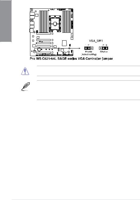
8.VGA Controller jumper (Pro WS C621-64L SAGE/10G only)
The VGA Controller jumper allows you to enable or disable the onboard VGA controller. Set to pins 1-2 to enable the onboard VGA.
1 Chapter
Ensure the ATX power supply is switched off or the power cord is detached from the power supply when enabling or disabling the VGA controller settings using this jumper.
•If a VGA Card is installed into a PCI Express x16 Slot, the onboard VGA function will still be enabled.
•BMC Remote Management Function will still be available when VGA controller settings is set to disabled, but the display will be disabled on the client device.
1-14 |
Chapter 1: Product Introduction |
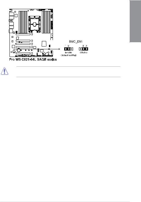
9.Baseboard Management Controller setting (Pro WS C621-64L SAGE/10G only)
The Baseboard Management Controller jumper allows you to enable or disable the on-board BMC.
Chapter 1
Ensure to set this BMC jumper to Enable to avoid system fan control and hardware monitor error.
ASUS Pro WS C621-64L SAGE Series |
1-15 |
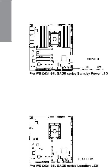
1.8 |
Onboard LEDs |
|
1. |
Standby Power LED |
|
1Chapter |
The Standby Power LED lights up to indicate that the system is ON, in sleep mode, |
|
in soft-off mode, or connected to a power source. This is a reminder that you should |
||
shut down the system and unplug the power cable before removing or plugging in any |
||
|
||
|
motherboard component. |
2.Location LED
The Location LED lights up when the Location button on the server is pressed or when triggered by a system management software. The Location LED helps visually locate and quickly identify the server in error on a server rack.
|
|
|
|
|
|
|
|
|
|
|
|
|
|
|
|
|
|
|
|
|
|
|
|
|
|
|
|
|
|
|
|
|
|
|
|
|
|
|
|
|
|
|
|
|
|
|
|
|
|
|
|
|
|
|
|
|
|
|
|
|
|
|
|
|
|
|
|
|
|
|
|
|
|
|
|
|
|
|
|
|
|
|
|
|
|
|
|
|
|
|
|
|
|
|
|
|
|
|
|
|
|
|
|
|
|
|
|
|
|
|
|
|
|
|
|
|
|
|
|
|
|
|
|
|
|
|
|
|
|
|
|
|
|
|
|
|
|
|
|
|
|
|
|
|
|
|
|
|
|
|
|
|
|
|
|
|
|
|
|
|
|
|
|
|
|
|
|
|
|
|
|
|
|
|
|
|
|
|
|
|
|
|
|
|
|
|
|
|
|
|
|
|
|
|
|
|
|
|
|
|
|
|
|
|
|
|
|
|
|
|
|
|
|
|
|
|
|
|
|
|
|
|
|
|
|
|
|
|
|
|
|
|
|
|
|
|
|
|
|
|
|
|
|
|
|
|
|
|
|
|
|
|
|
|
|
|
|
|
|
|
|
|
|
|
|
|
|
|
|
|
|
|
|
|
|
|
|
|
|
|
|
|
|
|
|
|
|
|
|
|
|
|
|
|
|
|
|
|
|
|
|
|
|
|
|
|
|
|
|
|
|
|
|
|
|
|
|
|
|
|
|
|
|
|
|
|
|
|
|
|
|
|
|
|
|
|
|
|
|
|
|
|
|
|
|
|
|
|
|
|
|
|
|
|
|
|
|
|
|
|
|
|
|
|
|
|
|
|
|
|
|
|
|
|
|
|
|
|
|
|
|
|
|
|
|
|
|
|
|
|
|
|
|
|
|
|
|
|
|
|
|
|
|
|
|
|
|
|
|
|
|
|
|
|
|
|
|
|
|
|
|
|
|
|
|
|
|
|
|
|
|
|
|
|
|
|
|
|
|
|
|
|
|
|
|
|
|
|
|
|
|
|
|
|
|
|
|
|
|
|
|
|
|
|
|
|
|
|
|
|
|
|
|
|
|
|
|
|
|
|
|
|
|
|
|
|
|
|
|
|
|
|
|
|
|
|
|
|
|
|
|
|
|
|
|
|
|
|
|
|
|
|
|
|
|
|
|
|
|
|
|
|
|
|
|
|
|
|
|
|
|
|
|
|
|
|
|
|
|
|
|
|
|
|
|
|
|
|
|
|
|
|
|
|
|
|
|
|
|
|
|
|
|
|
|
|
|
|
|
|
|
|
|
|
|
|
|
|
|
|
|
|
|
|
|
|
|
|
|
|
|
|
|
|
|
|
|
|
|
|
|
|
|
|
|
|
|
|
|
|
|
|
|
|
|
|
|
|
|
|
|
|
|
|
|
|
|
|
|
|
|
|
|
|
|
|
|
|
|
|
|
|
|
|
|
|
|
|
|
|
|
|
|
|
|
|
|
|
|
|
|
|
|
|
|
|
|
|
|
|
|
|
|
|
|
|
|
|
|
|
|
|
|
|
|
|
|
|
|
|
|
|
|
|
|
|
|
|
|
|
|
|
|
|
|
|
|
|
|
|
|
|
|
|
|
|
|
|
|
|
|
|
|
|
|
|
|
|
|
|
|
|
|
|
|
|
|
|
|
|
|
|
|
|
|
|
|
|
|
|
|
|
|
|
|
|
|
|
|
|
|
|
|
|
|
|
|
|
|
|
|
|
|
|
|
|
|
|
|
|
|
|
|
|
|
|
|
|
|
|
|
|
|
|
|
|
|
|
|
|
|
|
|
|
|
|
|
|
|
|
|
|
|
|
|
|
|
|
|
|
|
|
|
|
|
|
|
|
|
|
|
|
|
|
|
|
|
|
|
|
|
|
|
|
|
|
|
|
|
|
|
|
|
|
|
|
|
|
|
|
|
|
|
|
|
|
|
|
|
|
|
|
|
|
|
|
|
|
|
|
|
|
|
|
|
|
|
|
|
|
|
|
|
|
|
|
|
|
|
1-16 |
|
|
|
|
|
|
|
|
|
|
|
|
|
|
|
|
|
|
|
|
|
|
|
|
|
|
|
|
|
|
|
|
|
|
|
|
|
|
|
|
|
|
|
Chapter 1: Product Introduction |
 Loading...