

Page 1

P5Q3
Motherboard
Page 2

E4139
First Edition V1
August 2008
Copyright © 2008 ASUSTeK COMPUTER INC. All Rights Reserved.
No part of this manual, including the products and software described in it, may be reproduced,
transmitted, transcribed, stored in a retrieval system, or translated into any language in any form or by any
means, except documentation kept by the purchaser for backup purposes, without the express written
permission of ASUSTeK COMPUTER INC. (“ASUS”).
Product warranty or service will not be extended if: (1) the product is repaired, modied or altered, unless
such repair, modication of alteration is authorized in writing by ASUS; or (2) the serial number of the
product is defaced or missing.
ASUS PROVIDES THIS MANUAL “AS IS” WITHOUT WARRANTY OF ANY KIND, EITHER EXPRESS
OR IMPLIED, INCLUDING BUT NOT LIMITED TO THE IMPLIED WARRANTIES OR CONDITIONS OF
MERCHANTABILITY OR FITNESS FOR A PARTICULAR PURPOSE. IN NO EVENT SHALL ASUS, ITS
DIRECTORS, OFFICERS, EMPLOYEES OR AGENTS BE LIABLE FOR ANY INDIRECT, SPECIAL,
INCIDENTAL, OR CONSEQUENTIAL DAMAGES (INCLUDING DAMAGES FOR LOSS OF PROFITS,
LOSS OF BUSINESS, LOSS OF USE OR DATA, INTERRUPTION OF BUSINESS AND THE LIKE),
EVEN IF ASUS HAS BEEN ADVISED OF THE POSSIBILITY OF SUCH DAMAGES ARISING FROM ANY
DEFECT OR ERROR IN THIS MANUAL OR PRODUCT.
SPECIFICATIONS AND INFORMATION CONTAINED IN THIS MANUAL ARE FURNISHED FOR
INFORMATIONAL USE ONLY, AND ARE SUBJECT TO CHANGE AT ANY TIME WITHOUT NOTICE,
AND SHOULD NOT BE CONSTRUED AS A COMMITMENT BY ASUS. ASUS ASSUMES NO
RESPONSIBILITY OR LIABILITY FOR ANY ERRORS OR INACCURACIES THAT MAY APPEAR IN THIS
MANUAL, INCLUDING THE PRODUCTS AND SOFTWARE DESCRIBED IN IT.
Products and corporate names appearing in this manual may or may not be registered trademarks or
copyrights of their respective companies, and are used only for identication or explanation and to the
owners’ benet, without intent to infringe.
ii
Page 3

Contents
Contents ...................................................................................................... iii
Notices ........................................................................................................ vii
Safety information .................................................................................... viii
About this guide ......................................................................................... ix
P5Q3 specications summary ................................................................... xi
Chapter1: Product introduction
1.1 Welcome! ...................................................................................... 1-1
1.2 Package contents ......................................................................... 1-1
1.3 Special features ............................................................................ 1-2
1.3.1 Product highlights ........................................................... 1-2
1.3.2 ASUS unique features ................................................... 1-4
1.3.3 ASUS Exclusive Overclocking Features ......................... 1-7
Chapter 2: Hardware information
2.1 Before you proceed ..................................................................... 2-1
2.2 Motherboard overview ................................................................. 2-2
2.2.1 Motherboard layout ......................................................... 2-2
2.2.2 Layout contents ............................................................... 2-3
2.2.3 Placement direction ........................................................ 2-4
2.2.4 Screw holes .................................................................... 2-4
2.3 Central Processing Unit (CPU) ................................................... 2-5
2.3.1 Installing the CPU ........................................................... 2-5
2.3.2 Installing the CPU heatsink and fan ................................ 2-8
2.3.3 Uninstalling the CPU heatsink and fan ........................... 2-9
2.4 System memory ......................................................................... 2-10
2.4.1 Overview ....................................................................... 2-10
2.4.2 Memory congurations ...................................................2-11
2.4.3 Installing a DDR3 DIMM ............................................... 2-15
2.4.4 Removing a DDR3 DIMM ............................................. 2-15
2.5 Expansion slots .......................................................................... 2-16
2.5.1 Installing an expansion card ......................................... 2-16
2.5.2 Conguring an expansion card ..................................... 2-16
2.5.3 Interrupt assignments ................................................... 2-17
2.5.4 PCI slots ........................................................................ 2-18
2.5.5 PCI Express x1 slots ..................................................... 2-18
2.5.6 PCI Express 2.0 x16 slot ............................................... 2-18
iii
Page 4

Contents
2.6 Jumper ........................................................................................ 2-19
2.7 Connectors ................................................................................. 2-22
2.7.1 Rear panel connectors .................................................. 2-22
2.7.2 Internal connectors ....................................................... 2-24
2.8 Starting up for the rst time ...................................................... 2-36
2.9 Turning off the computer ........................................................... 2-37
2.9.1 Using the OS shut down function .................................. 2-37
2.9.2 Using the dual function power switch ............................ 2-37
Chapter 3: BIOS setup
3.1 Managing and updating your BIOS ............................................ 3-1
3.1.1 ASUS Update utility ........................................................ 3-1
3.1.2 ASUS EZ Flash 2 utility ................................................... 3-4
3.1.3 AFUDOS utility ................................................................ 3-5
3.1.4 ASUS CrashFree BIOS 3 utility ...................................... 3-7
3.2 BIOS setup program .................................................................... 3-8
3.2.1 BIOS menu screen .......................................................... 3-9
3.2.2 Menu bar ......................................................................... 3-9
3.2.3 Navigation keys ............................................................... 3-9
3.2.4 Menu items ................................................................... 3-10
3.2.5 Sub-menu items ............................................................ 3-10
3.2.6 Conguration elds ....................................................... 3-10
3.2.7 Pop-up window ............................................................. 3-10
3.2.8 Scroll bar ....................................................................... 3-10
3.2.9 General help ................................................................. 3-10
3.3 Main menu .................................................................................. 3-11
3.3.1 System Time [xx:xx:xx] ..................................................3-11
3.3.2 System Date [Day xx/xx/xxxx] ........................................3-11
3.3.3 Legacy Diskette A [1.44M, 3.5 in.] .................................3-11
3.3.4 Language [English] ........................................................3-11
3.3.5 SATA 1-6 ....................................................................... 3-12
3.3.6 Storage Conguration ................................................... 3-13
3.3.7 AHCI Conguration ....................................................... 3-14
3.3.8 System Information ....................................................... 3-15
3.4 Ai Tweaker menu ........................................................................ 3-16
3.4.1 Ai Overclock Tuner [Auto] ............................................. 3-16
3.4.2 CPU Ratio Setting [Auto] .............................................. 3-17
iv
Page 5

Contents
3.4.3 FSB Strap to North Bridge [Auto] .................................. 3-17
3.4.4 DRAM Frequency [Auto] ............................................... 3-17
3.4.5 DRAM Timing Control [Auto] ......................................... 3-18
3.4.6 DRAM Static Read Control [Auto] ................................. 3-19
3.4.7 DRAM Read Training [Auto] .......................................... 3-20
3.4.8 DRAM Write Training [Auto] .......................................... 3-20
3.4.9 MEM. OC Charger ........................................................ 3-20
3.4.10 Ai Clock Twister [Auto] .................................................. 3-20
3.4.11 Ai Transaction Booster [Auto] ....................................... 3-20
3.4.12 CPU Voltage [Auto] ...................................................... 3-21
3.4.13 CPU GTL Reference [Auto] ........................................... 3-21
3.4.14 CPU PLL Voltage [Auto] ................................................ 3-21
3.4.15 FSB Termination Voltage [Auto] .................................... 3-21
3.4.16 DRAM Voltage [Auto] .................................................... 3-21
3.4.17 NB Voltage [Auto] .......................................................... 3-21
3.4.18 SB Voltage [Auto] .......................................................... 3-22
3.4.19 PCIE SATA Voltage [Auto] ............................................. 3-22
3.4.20 Load-Line Calibration [Auto] ......................................... 3-22
3.4.21 CPU Spread Spectrum [Auto] ....................................... 3-22
3.4.22 PCIE Spread Spectrum [Auto] ...................................... 3-22
3.4.23 CPU Clock Skew [Auto] ................................................ 3-22
3.4.24 NB Clock Skew [Auto] ................................................... 3-23
3.4.25 CPU Margin Enhancement [Optimized] ........................ 3-23
3.5 Advanced menu ......................................................................... 3-23
3.5.1 CPU Conguration ........................................................ 3-23
3.5.2 Chipset .......................................................................... 3-25
3.5.3 Onboard Device Conguration ...................................... 3-26
3.5.4 USB Conguration ........................................................ 3-28
3.5.5 PCIPnP ......................................................................... 3-29
3.6 Power menu ................................................................................ 3-30
3.6.1 Suspend Mode [Auto] ................................................... 3-30
3.6.2 ACPI 2.0 Support [Disabled] ......................................... 3-30
3.6.3 ACPI APIC Support [Enabled] ....................................... 3-30
3.6.5 APM Conguration ........................................................ 3-31
3.6.6 Hardware Monitor ......................................................... 3-32
3.7 Boot menu .................................................................................. 3-34
v
Page 6

Contents
3.7.1 Boot Device Priority ...................................................... 3-34
3.7.2 Boot Settings Conguration .......................................... 3-35
3.7.3 Security ......................................................................... 3-36
3.8 Tools menu ................................................................................. 3-38
3.8.1 ASUS EZ Flash 2 .......................................................... 3-38
3.8.2 Drive Xpert Conguration .............................................. 3-39
3.8.3 Express Gate ................................................................ 3-40
3.8.4 ASUS O.C. Prole ......................................................... 3-41
3.8.5 AI NET 2........................................................................ 3-42
3.9 Exit menu .................................................................................... 3-43
Chapter 4: Software support
4.1 Installing an operating system ................................................... 4-1
4.2 Support DVD information ............................................................ 4-1
4.3 Software information ................................................................... 4-9
4.3.1 ASUS MyLogo™ ............................................................. 4-9
4.3.2 AI NET2 .........................................................................4-11
4.3.3 ASUS PC Probe II ......................................................... 4-12
4.3.4 Audio congurations ..................................................... 4-18
4.3.5 ASUS AI Suite ............................................................... 4-23
4.3.6 ASUS AI Nap ................................................................ 4-25
4.3.7 ASUS Fan Xpert ........................................................... 4-26
4.3.8 ASUS AI Booster ........................................................... 4-28
4.3.9 ASUS EPU—6 Engine .................................................. 4-29
4.3.10 ASUS AI Direct Link ...................................................... 4-33
4.3.11 ASUS Drive Xpert ......................................................... 4-35
4.3.12 ASUS Express Gate ..................................................... 4-39
4.4 RAID congurations .................................................................. 4-49
4.4.1 RAID denitions ............................................................ 4-49
4.4.2 Installing Serial ATA hard disks ..................................... 4-50
4.4.3 Intel® RAID congurations ............................................. 4-50
4.5 Creating a RAID driver disk ....................................................... 4-58
4.5.1 Creating a RAID driver disk without entering the OS .... 4-58
4.5.2 Creating a RAID driver disk in Windows® .................... 4-58
vi
Page 7

Notices
Federal Communications Commission Statement
This device complies with Part 15 of the FCC Rules. Operation is subject to the
following two conditions:
•
This device may not cause harmful interference, and
•
This device must accept any interference received including interference that
may cause undesired operation.
This equipment has been tested and found to comply with the limits for a
Class B digital device, pursuant to Part 15 of the FCC Rules. These limits are
designed to provide reasonable protection against harmful interference in a
residential installation. This equipment generates, uses and can radiate radio
frequency energy and, if not installed and used in accordance with manufacturer’s
instructions, may cause harmful interference to radio communications. However,
there is no guarantee that interference will not occur in a particular installation. If
this equipment does cause harmful interference to radio or television reception,
which can be determined by turning the equipment off and on, the user is
encouraged to try to correct the interference by one or more of the following
measures:
•
Reorient or relocate the receiving antenna.
•
Increase the separation between the equipment and receiver.
•
Connect the equipment to an outlet on a circuit different from that to which the
receiver is connected.
•
Consult the dealer or an experienced radio/TV technician for help.
The use of shielded cables for connection of the monitor to the graphics card is
required to assure compliance with FCC regulations. Changes or modications
to this unit not expressly approved by the party responsible for compliance
could void the user’s authority to operate this equipment.
Canadian Department of Communications Statement
This digital apparatus does not exceed the Class B limits for radio noise emissions
from digital apparatus set out in the Radio Interference Regulations of the
Canadian Department of Communications.
This class B digital apparatus complies with Canadian ICES-003.
vii
Page 8

Safety information
Electrical safety
•
To prevent electrical shock hazard, disconnect the power cable from the
electrical outlet before relocating the system.
•
When adding or removing devices to or from the system, ensure that the
power cables for the devices are unplugged before the signal cables are
connected. If possible, disconnect all power cables from the existing system
before you add a device.
•
Before connecting or removing signal cables from the motherboard, ensure
that all power cables are unplugged.
•
Seek professional assistance before using an adpater or extension cord.
These devices could interrupt the grounding circuit.
•
Make sure that your power supply is set to the correct voltage in your area.
If you are not sure about the voltage of the electrical outlet you are using,
contact your local power company.
•
If the power supply is broken, do not try to x it by yourself. Contact a
qualied service technician or your retailer.
Operation safety
•
Before installing the motherboard and adding devices on it, carefully read all
the manuals that came with the package.
•
Before using the product, make sure all cables are correctly connected and the
power cables are not damaged. If you detect any damage, contact your dealer
immediately.
•
To avoid short circuits, keep paper clips, screws, and staples away from
connectors, slots, sockets and circuitry.
•
Avoid dust, humidity, and temperature extremes. Do not place the product in
any area where it may become wet.
•
Place the product on a stable surface.
•
If you encounter technical problems with the product, contact a qualied
service technician or your retailer.
viii
This symbol of the crossed out wheeled bin indicates that the product (electrical,
electronic equipment and mercury-containing button cell battery) should not
be placed in municipal waste. Check local regulations for disposal of electronic
products.
Page 9

About this guide
This user guide contains the information you need when installing and conguring
the motherboard.
How this guide is organized
This guide contains the following parts:
• Chapter 1: Product introduction
This chapter describes the features of the motherboard and the new
technology it supports.
• Chapter 2: Hardware information
This chapter lists the hardware setup procedures that you have to perform
when installing system components. It includes description of the switches,
jumpers, and connectors on the motherboard.
• Chapter 3: BIOS setup
This chapter tells how to change system settings through the BIOS Setup
menus. Detailed descriptions of the BIOS parameters are also provided.
• Chapter 4: Software support
This chapter describes the contents of the support CD that comes with the
motherboard package and the software.
• Appendix: CPU features
The Appendix describes the CPU features and technologies that the
motherboard supports.
Where to nd more information
Refer to the following sources for additional information and for product and
software updates.
1. ASUS websites
The ASUS website provides updated information on ASUS hardware and
software products. Refer to the ASUS contact information.
2. Optional documentation
Your product package may include optional documentation, such as warranty
yers, that may have been added by your dealer. These documents are not
part of the standard package.
ix
Page 10

Conventions used in this guide
To make sure that you perform certain tasks properly, take note of the following
symbols used throughout this manual.
DANGER/WARNING: Information to prevent injury to yourself
when trying to complete a task.
CAUTION: Information to prevent damage to the components
when trying to complete a task.
IMPORTANT: Instructions that you MUST follow to complete a
task.
NOTE: Tips and additional information to help you complete a
task.
Typography
Bold text Indicates a menu or an item to select.
Italics
Used to emphasize a word or a phrase.
<Key> Keys enclosed in the less-than and greater-than sign
means that you must press the enclosed key.
Example: <Enter> means that you must press the
Enter or Return key.
<Key1+Key2+Key3> If you must press two or more keys simultaneously, the
key names are linked with a plus sign (+).
Example: <Ctrl+Alt+D>
Command Means that you must type the command exactly
as shown, then supply the required item or value
enclosed in brackets.
Example: At the DOS prompt, type the command line:
afudos /i[lename]
afudos /iP5Q3.ROM
x
Page 11

P5Q3
specications summary
CPU LGA775 socket for Intel® Core™2 Extreme/Core™2
Quad/ Core™2 Duo/Pentium® dual-core/Celeron® dualcore /Celeron® Processors
Compatible with Intel® 05B/05A/06 processors
Support Intel® 45nm Multi-Core CPU
* This motherboard isdesigned with VRD11.1 power
phase, and cannot be compatible with VRD10 designed
CPU. Please refer to www.asus.com for “CPU support
list”.
* Refer to www.asus.com for Intel CPU support list
Chipset Intel® P45 / ICH10R
System Bus 1600 / 1333 / 1066 / 800 MHz
Memory 4 x DIMM, max. 16GB, DDR3 1800 (O.C) / 1600 / 1333 /
1066 MHz, non-ECC, un-buffered memory
Dual channel memory architecture
* DDR3 1600 MHz or above DIMMs work only on the
Orange slots for one DIMM per channel.
* When installing total memory of 4GB capacity or more,
Windows® 32-bit operation system may only recognize
less than 3GB. Hence, a total installed memory of less
than 3GB is recomended.
* Please Refer to www.asus.com for the Memory QVL
(Qualied Vendors Lists).
Expansion Slots 2 x PCIe 2.0 x16, support ATI CrossFireX™ technology
dual at x 8 link (PCIe x16_1 blue, PCIe x16_2 black*)
3 x PCIe x1
2 x PCI
* PCIE x16 slot (black at max. x8 link)
Storage Intel® ICH10R Southbridge
- 6 x SATA 3Gb/s ports
- Intel® Matrix Storage, supporting SATA RAID 0,1, 5
and 10
JMicron® JMB363 SATA&PATA controllers
- 1 x UltraDMA 133/100/66 for up to 2 PATA devices
- 1 x External SATA 3Gb/s port (SATA On-the-Go)
JMicron® JMB322 (Drive Xpert Technology)
- 2 x SATA 3Gb/s ports
- Supports EZ Backup and Super Speed functions
LAN Realtek® 8111C PCIe Gb LAN controller, featuring AI
NET2
Audio Realtek® ALC1200 8-channel High Denition Audio
CODEC
- Supports Jack-detection, Multi-streaming, Front
Panel Jack-Retasking technology
- Coaxial/Optical S/PDIF out ports at back I/O
- ASUS Noise Filter
(continued on the next page)
xi
Page 12

P5Q3
specications summary
IEEE 1394 VIA6308 controller supports 2 x 1394a ports
USB Max. 12 USB2.0/1.1 ports(6 ports at mid-board, 6 ports
ASUS Unique Features ASUS Power Saving Solution:
ASUS Stylish Features ASUS MyLogo™
at back panel)
- ASUS EPU-6 Engine
- ASUS 8-phase Power Design
- ASUS AI Nap
ASUS Unique Features:
- ASUS Express Gate
- ASUS AI Direct Llink
ASUS Quiet Thermal Solution:
- ASUS Fanless Design: Heat-pipe solution
- ASUS Fan Xpert
ASUS EZ DIY:
- ASUS Q-Shield
- ASUS Drive Xpert
- ASUS Q-Connector
- ASUS O.C. Prole
- ASUS CrashFree BIOS 3
- ASUS EZ Flash 2
ASUS Exclusive
Overclocking Features
xii
ASUS AI Booster utility
Precision Tweaker 2:
- vCore: Adjustable CPU voltage at 6.25mV
increment
- vDIMM: 64-step DRAM voltage control
- vChipset (N.B.): 55-step chipset voltage control
- vFSB Termination: 35-step reference voltage control
- vCPU PLL: 64-step CPU PLL voltage control
SFS (Stepless Frequency Selection)
- FSB tuning from 200MHz up to 800MHz at 1MHz
increment
- PCI Express frequency tuning from 100MHz up to
180MHz at 1MHz increment
Overclocking Protection:
- ASUS C.P.R.(CPU Parameter Recall)
(continued on the next page)
Page 13

P5Q3
specications summary
Back Panel I/O Ports 1 x PS/2 Keyboard port
Internal I/O Connectors 3 x USB connectors support additional 6 USB ports
BIOS Features 8 Mb Flash ROM, AMI BIOS, PnP, DMI 2.0, WfM 2.0,
Manageability WOL by PME, WOR by PME, PXE, WOR by Ring,
Support CD Contents Drivers
Form Factor ATX Form Factor, 12”x 9.6” (30.5cm x 24.4cm)
*Specications are subject to change without notice.
1 x PS/2 Mouse port
1 x S/PDIF Out (Coaxial)
1 x S/PDIF Out (Optical)
1 x IEEE1394a
1 x RJ45 ports
1 x eSATA connector
6 x USB 2.0/1.1
8-channel Audio I/O
1 x Floppy disk drive connector
1 x COM connector
1 x IDE connector
1 x TPM connector
6 x SATA connectors (Red)
2 x Drive Xpert SATA connectors (Orange and white)
1 x CPU Fan connector
2 x Chassis Fan connectors
1 x Power Fan connector
1 x IEEE1394a connector
Front panel audio connector
1 x S/PDIF Out Header
Chassis Intrusion connector
CD audio in
24-pin ATX Power connector
1 x 8-pin ATX 12V Power connectors
System Panel (Q-Connector)
SM BIOS 2.4, ACPI 2.0
Chassis Intrusion
Express Gate
ASUS PC Probe II
ASUS Update
ASUS AI Suite
Anti-virus software (OEM version)
Image-Editing Suite
xiii
Page 14

xiv
Page 15

This chapter describes the motherboard
features and the new technologies
it supports.
Product
1
introduction
Page 16

Chapter summary
1
1.1 Welcome! ...................................................................................... 1-1
1.2 Package contents ......................................................................... 1-1
1.3 Special features ............................................................................ 1-2
ASUS P5Q3
Page 17

1.1 Welcome!
Thank you for buying an ASUS® P5Q3 motherboard!
The motherboard delivers a host of new features and latest technologies, making it
another standout in the long line of ASUS quality motherboards!
Before you start installing the motherboard, and hardware devices on it, check the
items in your package with the list below.
1.2 Package contents
Check your motherboard package for the following items.
Motherboard ASUS P5Q3
Cables 1 x 2-port Serial ATA power cable for 2 devices
4 x Serial ATA signal cables
1 x Ultra DMA 133/100/66 cable
Accessories 1 x ASUS Q-Shield (I/O shield)
1 x ASUS Q-Connector Kit (USB, system panel;
Retail version only)
Application CD ASUS motherboard Support DVD
Documentation User Manual
If any of the above items is damaged or missing, contact your retailer.
ASUS P5Q3 1-1
Page 18
1.3 Special features
1.3.1 Product highlights
Intel® Core™2 Extreme / Core™ 2 Quad /
Core™2 Duo Processor Support
This motherboard supports the latest Intel® Core™ 2 Extreme / Core™ 2 Quad /
Core™ 2 Duo processors in the LGA775 package. It is excellent for multi-tasking,
multi-media and enthusiastic gamers with 1600 / 1333 / 1066 / 800 MHz FSB. The
Intel® Core™ 2 series processor is one of the most powerful CPUs in the world. This
motherboard also supports Intel® CPUs in the new 45nm manufacturing process.
Intel® P45 Chipset
The Intel® P45 Chipset is the latest chipset designed to support 16GB of dual-
channel DDR3 1333/1066/800 MHz memory architecture, 1333/1066/800 MHz
FSB (Front Side Bus) and multi-core CPUs. It especially includes Intel
Memory Access technology that signicantly optimizes the use of available
memory bandwidth and reduces the latency of the memory accesses.
PCIe 2.0
This motherboard supports the latest PCIe 2.0 device for twice the current speed
and bandwidth. This enhances system performance while still providing backward
compatibility to PCIe 1.0 devices.
®
Fast
Dual-Channel DDR3 1800(O.C.) support
The motherboard supports DDR3 memory that features data transfer rates of
1800(O.C.)/1600/1333/1066/800 MHz to meet the higher bandwidth requirements
of the latest operation system, 3D graphics, multimedia, and Internet applications.
The dual-channel DDR3 architecture doubles the bandwidth of your system
memory to boost system performance. Furthermore, the supply voltage for the
memory is reduced from 1.8 V for DDR2 to just 1.5 V for DDR3. This voltage
reduction limits the power consumption and heat generation of DDR3 which makes
it an ideal memory solution.
1-2 Chapter 1: Product Introduction
Page 19
ATI CrossFireX Technolog support
ATI's CrossFireX boosts image quality along with rendering speed, eliminating
the need to scale down screen resolutions to get the high image quality you want.
CrossFire ignites with the higher antialiasing, anisotropic ltering, shading, and
texture settings you desire. Adjust your display congurations, experiment with
your advanced 3D settings, and check the effect with a real-time 3D-rendered
preview within ATI´s Catalyst™ Control Center to rule your CrossFireX system.
ASUS Express Gate
Taking only 5 seconds to go online from bootup, Express Gate is the one-stop
gateway to instant fun! It's a unique motherboard built-in OS. You can utilize the
most popular Instant Messengers (IM) like MSN, Skype, Google talk, QQ, and
Yahoo! Messenger to keep in touch with friends, or quickly check on the weather
and e-mails just before leaving your house. What's more, the user-friendly picture
manager lets you view your pictures without entering Windows at anytime!
The actual boot time depends on the system conguration.
Serial ATA 3Gb/s technology
This motherboard supports the hard drives based on the Serial ATA (SATA)
3Gb/s storage specication, delivering enhanced scalability and doubling the bus
bandwidth for high-speed data retrieval and saves. See page 2-27 for details.
IEEE 1394a support
The IEEE 1394a interface provides high speed digital interface for audio/video
appliances such as digital television, digital video camcorders, storage peripherals
& other PC portable devices. See page 2-30 for details.
S/PDIF digital sound ready
This motherboard provides convenient connectivity to external home theater audio
systems via coaxial and optical S/PDIF-out (SONY-PHILIPS Digital Interface)
jacks.It allows to transfer digital audio without converting to analog format and
keeps the best signal quality. See page 2-32 for details.
ASUS P5Q3 1-3
Page 20

High Denition Audio
Enjoy high-end sound quality on your PC! The onboard 8-channel HD audio (High
Denition Audio, previously codenamed Azalia) CODEC enables high-quality
192KHz/24-bit audio output that simultaneously sends different audio streams to
different destinations. You can now talk to your partners on the headphone while
playing multi-channel network games. See pages 2-22 and 2-23 for details.
100% Japan-made conductive polymer capacitors
This motherboard uses all Japan-made conductive polymer capacitors for
durability, improved lifespan and enhanced thermal capacity.
Green ASUS
This motherboard and its packaging comply with the European Union’s Restriction
on the use of Hazardous Substances (RoHS). This is in line with the ASUS vision
of creating environment-friendly and recyclable products/packagings to safeguard
consumers’ health while minimizing the impact on the environment.
1.3.2 ASUS unique features
ASUS Power Saving Solution
ASUS Power Saving solution intelligently and automatically provides balanced
computing power and energy consumption.
ASUS EPU-6 Engine
The new ASUS EPU - the world's rst power saving engine, has been upgraded
to a new six engine version, which provides total system power savings by
detecting current PC loadings and intelligently moderating power in real-time.
With auto phase switching for components (which includes the CPU, VGA card,
memory, chipset, drives and system fan), the EPU automatically provides the most
appropriate power usage via intelligent acceleration and overclocking - helping
save power and money.
1-4 Chapter 1: Product Introduction
Page 21

AI Nap
With AI Nap, the system can continue running at minimum power and noise
when you are temporarily away. To wake up the system and return to the OS
environment, simply click the mouse or press a key.
ASUS Quiet Thermal Solution
ASUS Quiet Thermal solution makes system more stable and enhances the
overclocking capability.
ASUS 8-Phase Power Design
Longer Life, & Higher Efciency!
With power efciency so important to operating temperatures, ASUS 8-phase
VRM design leads the industry with its 96% power efciency. High quality power
components such as low RDS (on) MOSFETs for minimum switching loss & lower
temperatures, Ferrite core chokes with lower hysteresis loss, and high quality
Japanese-made conductive polymer capacitors all add up to ensure longer
component life and lower power loss - creating more energy efciency.
Fan Xpert
“ASUS Fan Xpert intelligently allows users to adjust both the CPU and chassis fan
speed according to different ambient temperature , which is caused by different
climate conditions in different geographic regions and system loading.Built-in
variety of useful proles offer exible controls of fan speed to achieve a quiet and
cool environment.”
Fanless Design and Heat-pipe
The ASUS fanless design allows multi-directional heat ow from major thermal
sources in the motherboard to lower overall system temperature, resulting in
quieter operation and longer system life. ASUS has devoted special efforts to
address the thermal issues across the motherboard, and most notably in the
following areas: CPU, power, VGA, Northbridge and Southbridge. The heat pipe,
heatsink, and strategic board layout were tailor made to dissipate heat in the most
efcient manner.
ASUS Crystal Sound
This feature can enhance speech-centric applications like Skype, online game,
video conference and recording.
ASUS P5Q3 1-5
Page 22

Noise Filter
This feature detects repetitive and stationary noises (non-voice signals) like
computer fans, air conditioners, and other background noises then eliminates it in
the incoming audio stream while recording.
ASUS EZ DIY
ASUS EZ DIY feature collection provides you easy ways to install computer
components, update the BIOS or back up your favorite settings.
Drive Xpert
Without drivers or BIOS setups, the ASUS exclusive Drive Xpert is ideal for anyone
who needs to secure data on their hard drives or enhance hard drive performances
without the hassles of complicated congurations. With Drive Xpert's user-friendly
graphical user interface, users can easily arrange hard drive backups or enhance
their hard drive transfer rates - making sure that data is looked after every moment,
every day.
ASUS AI Direct Link
AI Direct Link can easily and efciently transfer large amounts of data via the
network cable - saving up to 70% of the total time taken. With AI Direct Link, it
becomes easy to backup or share large data les like movies or other media
content.
ASUS Q-Shield
Easy and Comfortable Installations
The specially designed ASUS Q-Shield does without the usual "ngers" - making
it convenient and easy to install. With better electric conductivity, it ideally protects
your motherboard against static electricity and shields it against Electronic
Magnetic Interference (EMI).
ASUS Q-Connector
ASUS Q-Connector allows you to easily connect or disconnect the chassis front
panel cables to the motherboard. This unique module eliminates the trouble of
connecting the system panel cables one at a time and avoiding wrong cable
connections. See page 2-35 for details.
1-6 Chapter 1: Product Introduction
Page 23

ASUS O.C. Prole
The motherboard features the ASUS O.C. Prole that allows users to conveniently
store or load multiple BIOS settings. The BIOS settings can be stored in the
CMOS or a separate le, giving users freedom to share and distribute their favorite
settings. See page 4-35 for details.
ASUS CrashFree BIOS 3
The ASUS CrashFree BIOS 3 allows users to restore corrupted BIOS data from a
USB ash disk containing the BIOS le.
ASUS EZ Flash 2
EZ Flash 2 is a user-friendly BIOS update utility. Simply press the predened
hotkey to launch the utility and update the BIOS without entering the OS. Update
your BIOS easily without preparing a bootable diskette or using an OS-based ash
utility.
ASUS MyLogo™
ASUS MyLogo personalizes and adds style to your system with customizable boot
logos.
1.3.3 ASUS Exclusive Overclocking Features
AI Booster
The ASUS AI Booster allows you to overclock the CPU speed in Windows
environment without the hassle of booting the BIOS.
Precision Tweaker 2
Allows the user to adjust the NB Voltage, FSB termination Voltage, CPU PLL
Voltage and the DRAM Voltage in 0.02v steps to netune voltages to achieve the
most precise setting for the ultimate customized overclocking conguration.
C.P.R. (CPU Parameter Recall)
The C.P.R. feature of the motherboard BIOS allows automatic re-setting to the
BIOS default settings in case the system hangs due to overclocking. When the
system hangs due to overclocking, C.P.R. eliminates the need to open the system
chassis and clear the RTC data. Simply shut down and reboot the system, and the
BIOS automatically restores the CPU default setting for each parameter.
ASUS P5Q3 1-7
Page 24

1-8 Chapter 1: Product Introduction
Page 25

This chapter lists the hardware setup
procedures that you have to perform
when installing system components. It
includes description of the jumpers and
connectors on the motherboard.
Chapter 2: Hardware
2
information
Page 26

Chapter summary
2
2.1 Before you proceed ..................................................................... 2-1
2.2 Motherboard layout ...................................................................... 2-2
2.3 Motherboard overview ................................................................. 2-4
2.4 System memory ......................................................................... 2-10
2.5 Expansion slots .......................................................................... 2-16
2.6 Jumper ........................................................................................ 2-19
2.7 Connectors ................................................................................. 2-22
2.8 Starting up for the rst time ...................................................... 2-36
2.7 Turning off the computer ........................................................... 2-37
ASUS P5Q3
Page 27
2.1 Before you proceed
Take note of the following precautions before you install motherboard components
or change any motherboard settings.
• Unplug the power cord from the wall socket before touching any
component.
• Use a grounded wrist strap or touch a safely grounded object or a metal
object, such as the power supply case, before handling components to
avoid damaging them due to static electricity.
• Hold components by the edges to avoid touching the ICs on them.
• Whenever you uninstall any component, place it on a grounded antistatic
pad or in the bag that came with the component.
• Before you install or remove any component, ensurethat the ATX power
supply is switched off or the power cord is detached from the power
supply. Failure to do so may cause severe damage to the motherboard,
peripherals, and/or components.
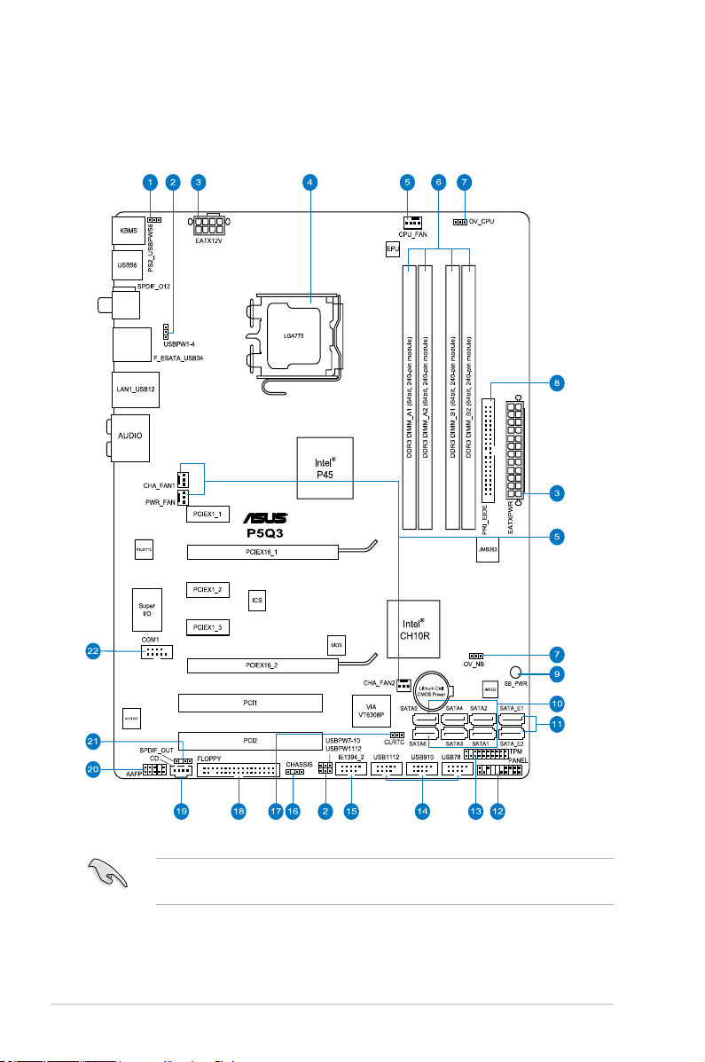
Onboard LED
The motherboard comes with a standby power LED. The green LED lights up
to indicate that the system is ON, in sleep mode, or in soft-off mode. This is a
reminder that you should shut down the system and unplug the power cable before
removing or plugging in any motherboard component. The illustration below shows
the location of the onboard LED.
ASUS P5Q3 2-1
Page 28
2.2 Motherboard overview
2.2.1 Motherboard layout
Refer to
2.7 Connectors
internal connectors.
2-2 Chapter 2: Hardware information
for more information about rear panel connectors and
Page 29

2.2.2 Layout contents
Connectors/Jumpers/Slots Page
1 PS2 keyboard/mouse wake-up (3-pin PS2_USBPW56)
2. USB device wake-up (3-pin USBPW1-4, PS2_USBPW56,
USBPW7-10, USBPW1112)
3. ATX power connectors (24-pin EATXPWR, 8-pin EATX12V)
4. LGA775 CPU socket
5. CPU, chassis, and power fan connectors
(4-pin CPU_FAN, 3-pin CHA_FAN1-2, 3-pin PWR_FAN)
6. DDR3 DIMM slots 2-10
7. CPU / Northbridge overvoltage setting
(3-pin OV_CPU, 3-pin OV_NB)
8. IDE connector (40-1 pin PRI_EIDE) 2-26
9. Standby power LED (SB_PWR) 2-1
10. ICH10R Serial ATA connectors (7-pin SATA1-6) 2-27
11. JMicron® Serial ATA RAID connectors
(7-pin SATA_E1, 7-pin SATA_E2)
12. System panel connector (20-8 pin PANEL)
13. TPM connector (20-1 pin TPM) 2-33
14. USB connectors (10-1 pin USB78, USB910, USB1112)
15. IEEE 1394a port connector (10-1 pin IE1394_2)
16. Chassis intrusion connector (4-1 pin CHASSIS)
17. Clear RTC RAM (3-pin CLRTC)
18. Floppy disk drive connector (34-1 pin FLOPPY)
19. Optical drive audio connector (4-pin CD)
20. Front panel audio connector (10-1 pin AAFP)
21. Digital audio connector (4-1 pin SPDIF_OUT for
ASUS HDMI VGA card)
22. Serial port connector (10-1 pin COM1)
2-22
2-22
2-34
2-5
2-31
2-21
2-28
2-35
2-28
2-30
2-32
2-30
2-25
2-31
2-33
2-32
2-29
ASUS P5Q3 2-3
Page 30
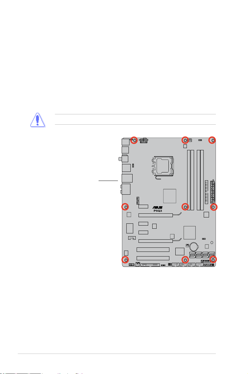
2.2.3 Placement direction
When installing the motherboard, make sure that you place it into the chassis in the
correct orientation. The edge with external ports goes to the rear part of the chassis
as indicated in the image below.
2.2.4 Screw holes
Place six (9) screws into the holes indicated by circles to secure the motherboard
to the chassis.
DO NOT overtighten the screws! Doing so can damage the motherboard.
Place this side towards
the rear of the chassis
2-4 Chapter 2: Hardware information
Page 31

2.3 Central Processing Unit (CPU)
The motherboard comes with a surface mount LGA775 socket designed for the
Intel® Core™2 Extreme/Core™2 Quad/ Core™2 Duo/Pentium® dual-core/Celeron® dualcore /Celeron® Processors
• Make sure that all power cables are unplugged before installing the CPU.
• I f in st al li ng a d ua l-core CPU, connect the c ha ss is fan cab le to th e
CHA_FAN1 connector to ensure system stability.
• Due to the chipset limitation, we recommend you use FSB 800MHz CPU or
above.
•
Upon purchase of the motherboard, make sure that the PnP cap is on
the socket and the socket contacts are not bent. Contact your retailer
immediately if the PnP cap is missing, or if you see any damage to the PnP
cap/socket contacts/motherboard components. ASUS will shoulder the cost
of repair only if the damage is shipment/transit-related.
•
Keep the cap after installing the motherboard. ASUS will process Return
Merchandise Authorization (RMA) requests only if the motherboard comes
with the cap on the LGA775 socket.
• The product warranty does no t cov er da mage to the socket contacts
resulting from incorrect CPU installation/removal, or misplacement/loss/
incorrect removal of the PnP cap.
2.3.1 Installing the CPU
To install a CPU:
1. Locate the CPU socket on the motherboard.
Before installing the CPU, make sure that the cam box is facing towards you
and the load lever is on your left.
ASUS P5Q3 2-5
Page 32

2. Press the load lever with your thumb
(A), then move it to the left (B) until
it is released from the retention tab.
Retention tab
A
To prevent damage to the socket
pins, do not remove the PnP cap
unless you are installing a CPU.
3. Lift the load lever in the direction of
the arrow to a 135º angle.
4. Lift the load plate with your thumb
and forenger to a 100º angle (4A),
then push the PnP cap from the load
plate window to remove (4B).
5. Position the CPU over the socket,
making sure that the gold triangle
is on the bottom-left corner of the
socket then t the socket alignment
key into the CPU notch.
The CPU ts in only one correct
orientation. DO NOT force the
CPU into the socket to prevent
bending the connectors on the
socket and damaging the CPU!
B
Load lever
PnP cap
Load plate
4B
4A
3
CPU notch
Gold
triangle
mark
Alignment key
2-6 Chapter 2: Hardware information
Page 33

6. Apply several drops of thermal paste
to the exposed area of the CPU that
the heatsink will be in contact with,
ensuring that it is spread in an even
thin layer.
Som e heatsinks come with
pre -applied thermal paste. If
so, skip this step.
The Thermal Interface Material is toxic and inedible. If it gets into your eyes
or touches your skin, ensure to wash it off immediately, and seek professional
medical help.
To prevent contaminating the paste, DO NOT spread the paste with your nger
directly.
7. Close the load plate (A), then push
the load lever (B) until it snaps into
the retention tab.
A
B
The motherboard supports Intel® LGA775 processors with the Intel® Enhanced
Memory 64 Technology (EM64T), Enhanced Intel SpeedStep® Technology
(EIST), and Hyper-Threading Technology. Refer to the Appendix for more
information on these CPU features.
ASUS P5Q3 2-7
Page 34

2.3.2 Installing the CPU heatsink and fan
The Intel® LGA775 processor requires a specially designed heatsink and fan
assembly to ensure optimum thermal condition and performance.
•
When you buy a boxed Intel® processor, the package includes the CPU fan
and heatsink assembly. If you buy a CPU separately, make sure that you
use only Intel®-certied multi-directional heatsink and fan.
•
Your Intel® LGA775 heatsink and fan assembly comes in a push-pin design
and requires no tool to install.
•
If you purchased a separate CPU heatsink and fan assembly, make sure
that you have properly applied Thermal Interface Material to the CPU
heatsink or CPU before you install the heatsink and fan assembly.
Make sure that you have installed the motherboard to the chassis before you
install the CPU fan and heatsink assembly.
If you purchased a separate CPU heatsink and fan assembly, ensure that the
Thermal Interface Material is properly applied to the CPU heatsink or CPU
before you install the heatsink and fan assembly.
To install the CPU heatsink and fan:
1. Place the heatsink on top of the
installed CPU, making sure that the
B
A
B
four fasteners match the holes on
the motherboard.
2. Push down two fasteners at a time in
A
a diagonal sequence to secure the
heatsink and fan assembly in place.
A
B
2-8 Chapter 2: Hardware information
B
1
A
Orient the heatsink and fan assembly such that the CPU fan cable is closest to
the CPU fan connector.
1
Page 35

3. Connect the CPU fan cable to the connector on the motherboard labeled
CPU_FAN.
DO NOT forget to connect the CPU fan connector! Hardware monitoring errors
can occur if you fail to plug this connector.
2.3.3 Uninstalling the CPU heatsink and fan
To uninstall the CPU heatsink and fan:
1. Disconnect the CPU fan cable from
the connector on the motherboard.
2. Rotate each fastener
B
A
B
counterclockwise.
3. Pull up two fasteners at a time in a
diagonal sequence to disengage the
A
heatsink and fan assembly from the
motherboard.
A
B
B
A
4. Carefully remove the heatsink and fan assembly from the motherboard.
ASUS P5Q3 2-9
Page 36

2.4 System memory
2.4.1 Overview
The motherboard comes with four Double Data Rate 3 (DDR3) Dual Inline Memory
Modules (DIMM) sockets.
The gure illustrates the location of the DDR3 DIMM sockets:
Channel Sockets
Channel A DIMM_A1 and DIMM_A2
Channel B DIMM_B1 and DIMM_B2
2-10 Chapter 2: Hardware information
Page 37

2.4.2 Memory congurations
You may install 512 MB, 1 GB, 2 GB and 4GB unbuffered non-ECC DDR3 DIMMs
into the DIMM sockets.
• You may install varying memory sizes in Channel A and Channel B. The
system maps the total size of the lower-sized channel for the dual-channel
conguration. Any excess memory from the higher-sized channel is then
mapped for single-channel operation.
• It recommended that to install the memory module from orange slots for
better overclocking capability.
• Always install DIMMs with the same CAS latency. For optimum compatibility,
it is recommended that you obtain memory modules from the same vendor.
• When installing total memory of 4GB capacity or more, Windows 32-bit
operation system may only recognize less than 3GB. Hence, a total installed
memory of less than 3GB is recommended.
• This motherboard does not support memory modules made up of 256 Mb
chips.
• Due to chipset limitation, this motherboard can only support up to 16 GB
on the operating systems listed below. You may install a maximum of 4 GB
DIMMs on each slot.
Windows® XP Professional x64 Edition
• The default memory operation frequency is dependent on its SPD. Under
the default state, some memory modules for overclocking may operate at a
lower frequency than the vendor-marked value. To operate at the vendormarked or at a higher frequency, see section
manual memory frequency adjustment.
• The memory modules may require a better cooling system to work stably
under full loading (4 DIMMs) or overclocking setting.
Windows
64-bit
®
Vista x64 Edition
3.4 Ai Tweaker menu
for
ASUS P5Q3 2-11
Page 38

P5Q3 Motherboard Qualied Vendors Lists (QVL)
DDR3-1066MHz capability
Size Vendor Chip No. CL Chip Brand SS/DS Part No. DIMM socket
512MB AENEON AEH93R10F A 7 AENEON SS AEH660UD00-10FA98X V V
1024MB AENEON AEH93R10F A 7 AENEON DS AEH760UD00-10FA98X V V
1024MB A-DATA J5308BASE-AE-E-S N/A ELPIDA DS M3OEL3G3I4130A1B5Z V V V
1024MB CORSAIR Heat-Sink Package 7 N/A DS CM3X1024-1066C7 V V V
1024MB Crucial Z9HWQ 7 MICRON SS CT12864BA1067.8SFB V V V
1024MB
2048MB
1024MB ELPIDA J5308BASE-AC-E 8 ELPIDA DS EBJ11UD8BAFA-AG-E V V V
512MB Elpida J5308BASE-AC-E 6 elpida SS EBJ51UD8BAFA-AC-E V V V
512MB Elpida J5308BASE-AC-E 7 elpida SS EBJ51UD8BAFA-AE-E V V V
1024MB Elpida J5308BASE-AC-E 7 elpida DS EBJ11UD8BAFA-AE-E V V V
1024MB
2048MB(Kit of 2) G.SKILL Heat-Sink Package 6-6-6-15 N/A SS F3-8500CL6D-2GBHK V V V
1024MB Hynix H5TQ1G83AFPG7C 7 HYNIX SS HMT112U6AFP8C-G7N0 V V V
1024MB Hynix HY5TQ1G831ZNFP-G7 7 HYNIX SS HYMT112U64ZNF8-G7 V V V
2048MB Hynix H5TQ1G83AFPG7C 7 HYNIX DS HMT125U6AFP8C-G7N0 V V V
2048MB Hynix HY5TQ1G831ZNFP-G7 7 HYNIX DS HYMT125U64ZNF8-G7 V V V
1024MB Kingston J5308BASE-AC-E 7 ELPIDA DS KVR1066D3N7/1G V V V
2048MB Kingston K4B1G0846C-ZCF8 N/A N/A DS KVR1066D3N7/2G V V V
512MB Kingston J5308BASE-AC-E N/A elpida SS KVR1066D3N7/512 V V V
1024MB Kingston J5308BASE-AC-E N/A elpida DS KVR1066D3N7/1G V V V
2048MB Kingston K4B1G0846C-ZCF8 N/A Samsung DS KVR1066D3N7/2G V V V
1024MB MICRON 7VD22 7 MICRON SS MT8JTF12864AY-1G1D1 V V V
2048MB MICRON 7VD22 7 MICRON DS MT16JTF25664AY-1G1D1 V V V
1024MB Qimonda IDSH1G-03A1F1C-
1024MB Qimonda IDSH1G-03A1F1C-
2048MB Qimonda IDSH1G-03A1F1C-
2048MB Qimonda IDSH1G-03A1F1C-
1024MB Qimonda IDSH1G-03A1F1C-10F 7 QIMONDA SS IMSH1GU03A1F1C-10F V V V
1024MB Qimonda IDSH1G-03A1F1C-10G 8 QIMONDA SS IMSH1GU03A1F1C-10G V V V
1024MB Qimonda IDSH51-03A1F1C-10F N/A QIMONDA DS IMSH1GU13A1F1C-10F V V V
2048MB Qimonda IDSH1G-03A1F1C-10F 7 QIMONDA DS IMSH2GU13A1F1C-10F V V V
2048MB Qimonda IDSH1G-03A1F1C-10G 8 QIMONDA DS IMSH2GU13A1F1C-10G V V V
1024MB Samsung K4B1G0846C-ZCG8 6 Samsung SS M378B2873CZ0-CG8 V V
1024MB Samsung K4B1G0846C-ZCF8 8 Samsung SS M378B2873CZ0-CF8 V V V
1024MB WINTEC IDSH51-03A1F1C-10F 7 QIMONDA DS 3DU3191A-10 V V V
crucial D9JNL
Crucial D9JNL 7 MICRON DS CT25664BA1067.16SFD V V V
G.SKILL Heat-Sink Package
10FFSS15085
10GFSS14526
10FFSS15085
10GFSS13467
7 MICRON
N/A G.SKILL
N/A Qimonda SS IMSH1GU03A1F1C-10F V V V
N/A Qimonda SS IMSH1GU03A1F1C-10G V V V
N/A Qimonda DS IMSH2GU03A1F1C-10F V V
N/A Qimonda DS IMSH2GU03A1F1C-10G V V V
CT12864BA1067.8SFD V
SS
F3-8500CL6D-2GBHK V
SS
support
(Optional)
A* B* C*
V V
V
2-12 Chapter 2: Hardware information
Page 39

P5Q3 Motherboard Qualied Vendors Lists (QVL)
DDR3-1333MHz capability
Size Vendor Chip No. CL Chip
1024MB AENEON AEH93R13H N/A AENEON DS AEH760UD00-13H V V
1024MB Aeneon AEH93R13H 9 AENEON DS AEH760UD00-13H V V V
2048MB A-DATA K4B1G0846D 9 SAMSUNG DS SC63I1B16 V V V
1024MB BUFFALO Heat-Sink Package 7-7-7-20 N/A SS FSX1333D3G-1G V V V
2048MB BUFFALO Heat-Sink Package 7-7-7-20 N/A DS FSX1333D3G-2G V
1024MB
2048MB CENTURY 8DD22D9JNM N/A N/A DS PC3-10600 DDR3-1333
4096MB(Kit of 2) CORSAIR Heat-Sink Package 9-9-9-24 N/A DS BoxP/N:
2048MB(Kit of 2) CORSAIR Heat-Sink Package 9-9-9-24 N/A DS BoxP/N:TWIN3X2048-
1024MB CORSAIR Heat-Sink Package 9 N/A DS CM3X1024-1333C9DHX V V V
1024MB Corsair Heat-Sink Package 9 Corsair DS CM3X1024-1333C9DHX V V V
1024MB crucial D9GTS 9 MICRON SS CT12864BA1339.8SFB V V V
2048MB crucial D9JNM 9 MICRON DS CT25664BA1339.16SFD V V V
2048MB(Kit of 2) G.SKILL Heat-Sink Package 7-7-7-18 N/A SS F3-10600CL7D-2GBPI V V V
2048MB(Kit of 2) G.SKILL Heat-Sink Package 8-8-8-21 N/A SS F3-10600CL8D-2GBHK V V V
2048MB(Kit of 2) G.SKILL Heat-Sink Package 9-9-9-24 N/A SS F3-10600CL9D-2GBPK V V V
2048MB(Kit of 2) G.SKILL Heat-Sink Package 9-9-9-24 N/A DS F3-10600CL9D-2GBNQ V V V
4096MB(Kit of 2) G.SKILL Heat-Sink Package 9-9-9-24 N/A DS F3-10666CL9D-4GBPK V V V
2048MB G.SKILL Heat-Sink Package N/A G.SKILL DS F3-10666CL9D-4GBPK V V V
1024MB G.SKILL Heat-Sink Package N/A G.SKILL SS F3-10600CL9D-2GBPK V V V
1024MB G.SKILL Heat-Sink Package N/A G.SKILL SS F3-10600CL8D-2GBHK V V V
1024MB KINGMAX 8LD22D9JNM N/A MICRON SS FLFD45F-B8EE9 V V V
2048MB KINGMAX 8LD22D9JNM N/A MICRON DS FLFE85F-B8MF9 V V
1024MB KINGMAX J1108BASE-DJ-E N/A ELPIDA SS FLFD45F-B8EE9 V V V
1024MB Kingston J1108BASE-DJ-E N/A ELPIDA SS KVR1333D3N9/1G V V V
2048MB Kingston J1108BASE-DJ-E N/A ELPIDA DS KVR1333D3N9/2G V V V
1024MB MICRON Z9HWR 9 MICRON SS MT8JTF12864AY-
2048MB MICRON Z9HWR 9 MICRON DS MT16JTF25664AY-
2048MB OCZ Heat-Sink Package N/A OCZ DS OCZ3P13334GK V V V
1024MB OCZ Heat-Sink Package 6-5-5 N/A SS OCZ3RPX1333EB2GK V V V
4096MB(Kit of 2) OCZ Heat-Sink Package 7 N/A DS OCZ3P13334GK V V
1024MB(Kit of 2) Patriot Heat-Sink Package 7 Patriot SS PDC32G1333LLK V
1024MB Qimonda IDSH1G-03A1F1C-
1024MB Qimonda IDSH1G-03A1F1C-13H N/A N/A SS IMSH1GU03A1F1C-13H V V V
2048MB Qimonda IDSH1G-03A1F1C-13H N/A N/A DS IMSH2GU13A1F1C-13H V V V
1024MB Samsung K4B1G0846D-HCH9 9 Samsung SS M391B2873DZ1-CH9 V V
1024MB Samsung K4B1G0846D-HCH9 9 Samsung SS M378B2873DZ1-CH9 V V
2048MB Samsung K4B1G0846D-HCH9 9 Samsung DS M391B5673DZ1-CH9 V V V
2048MB Samsung K4B1G0846D-HCH9 9 Samsung DS M378B5673DZ1-CH9 V V V
1024MB SAMSUNG K4B1G0846D 9 SAMSUNG SS M378B2873DZ1-CH9 V V V
1024MB SAMSUNG K4B1G0846D(ECC) 9 SAMSUNG SS M391B2873DZ1-CH9 V V V
2048MB SAMSUNG K4B1G0846D 9 SAMSUNG DS M378B5673DZ1-CH9 V V V
2048MB SAMSUNG K4B1G0846D(ECC) 9 SAMSUNG DS M391B5673DZ1-CH9 V V V
2048MB Transcend SEC816HCH9K4B1G0846D N/A N/A DS TS256MLK64V3U V V V
1024MB Transcend SCE813HCH9K4B1G0846D N/A N/A SS TS128MLK64V3U V V V
1024MB Transcend K4B1G0846D 9 SAMSUNG SS TS128MLK64V3U V V V
2048MB Transcend K4B1G0846D 9 SAMSUNG DS TS256MLK64V3U V V V
8FD22D9JNM N/A
CENTURY
13HFSS10513
N/A Qimonda SS IMSH1GU03A1F1C-13H V V V
SS/DS Part No. DIMM socket
Brand
SS PC3-10600 DDR3-1333
N/A
9-9-9
9-9-9
TW3X4G1333C9DHX
(CM3X20481333C9DHX)
1333C9(CM3X10241333C9)
1G4BYES
1G4BYES
support
(Optional)
A* B* C*
V V
V V V
V V V
V V V
V V V
V V V
V
ASUS P5Q3 2-13
Page 40

P5Q3 Motherboard Qualied Vendors Lists (QVL)
DDR3-1600MHz capability
Size Vendor Chip No. CL Chip Brand SS/DS Part No. DIMM socket
1024MB Aeneon Heat-Sink Package 9 N/A SS AXH760UD10-16H V V V
2048MB Aeneon Heat-Sink Package 9 N/A DS AXH860UD20-16H V V
1024MB CORSAIR Heat-Sink Package 7 N/A SS CM3X1024-
1024MB Crucial Heat-Sink Package N/A PQI SS BL12864BA1608.8SFB(XMP) V V V
2048MB(Kit of 2) G.SKILL Heat-Sink Package 7-7-7-18 N/A SS F3-12800CL7D-2GBHZ V V V
4096MB(Kit of 2) G.SKILL
4096MB(Kit of 2) Kingston Heat-Sink Package N/A N/A SS KHX12800D3K2/4G V V
1024MB OCZ Heat-Sink Package N/A N/A SS OCZ3T1600XM2GK V V V
4096MB(Kit of 2) OCZ Heat-Sink Package 776 N/A DS OCZ3P1600EB4GK V V
2048MB OCZ Heat-Sink Package OCZ3X16004GK V V
2048MB(Kit of 2) Kingston Heat-Sink Package N/A N/A SS KHX13000D3LLK2/2G V V V
2048MB(Kit of 2) Kingston
1024MB Kingston Heat-Sink Package SS KHX13000D3LLK2/2G V V
Heat-Sink Package 7-7-7-18
Heat-Sink Package
N/A
N/A N/A
1600C7DHXIN(XMP)
DS F3-12800CL7D-4GBPI
KHX13000D3LLK2/
SS
2GX(XMP)
support
(Optional)
A* B* C*
V V
V V
V V
V
P5Q3 Motherboard Qualied Vendors Lists (QVL)
DDR3-1800MHz capability
Size Vendor Chip No. CL Chip Brand SS/DS Part No. DIMM socket
1024MB CORSAIR Heat-Sink Package 7-7-7-20 N/A SS CM3X1024-
1024MB Kingston Heat-Sink Package N/A N/A SS KHX14400D3/1G V
2048MB(Kit of 2) Kingston Heat-Sink Package N/A N/A SS KHX14400D3K2/2G V
1800C7DIN(XMP)
SS - Single-sided / DS - Double-sided
DIMM support:
• A*: Supports one modules inserted into eithor slot as Single-channel
memory conguration.
• B*: Supports one pair of modules inserted into eithor the yellow slots or
the black slots as one pair of Dual-channel memory conguration.
• C*: Supports 4 modules inserted into both the yellow and black slots as
two pairs of Dual-channel memory conguration.
support
(Optional)
A* B* C*
V
• It is recommended to install the memory modules from the orange slot for
better overclocking capability.
• The O.C. mode is not guaranteed. It depends on whole system
conguration and other parameters. For the setting, memory may need a
external cooling device, such as fan, to work stably under high frequency/
voltage setting.
Visit the ASUS website for the latest QVL.
2-14 Chapter 2: Hardware information
Page 41

2.4.3 Installing a DDR3 DIMM
Make sure to unplug the power supply before adding or removing DIMMs or
other system components. Failure to do so may cause severe damage to both
the motherboard and the components.
1. Unlock a DDR3 DIMM socket
by pressing the retaining clips
outward.
2. Align a DIMM on the socket
such that the notch on the DIMM
matches the break on the socket.
1
Unlocked retaining clip
A DDR3 DIMM is keyed with a notch so that it ts in only one direction. DO NOT
force a DIMM into a socket to avoid damaging the DIMM.
2
DDR3 DIMM notch
1
3. Firmly insert the DIMM into the
3
socket until the retaining clips snap
back in place and the DIMM is
properly seated.
Locked Retaining Clip
2.4.4 Removing a DDR3 DIMM
Follow these steps to remove a DIMM.
1. Simultaneously press the
retaining clips outward to unlock
the DIMM.
1
Support the DIMM lightly with your ngers when pressing the retaining clips.
The DIMM might get damaged when it ips out with extra force.
2. Remove the DIMM from the socket.
ASUS P5Q3 2-15
2
1
DDR3 DIMM notch
Page 42

2.5 Expansion slots
In the future, you may need to install expansion cards. The following sub-sections
describe the slots and the expansion cards that they support.
Make sure to unplug the power cord before adding or removing expansion
cards. Failure to do so may cause you physical injury and damage motherboard
components.
2.5.1 Installing an expansion card
To install an expansion card:
1. Before installing the expansion card, read the documentation that came with
it and make the necessary hardware settings for the card.
2. Remove the system unit cover (if your motherboard is already installed in a
chassis).
3. Remove the bracket opposite the slot that you intend to use. Keep the screw
for later use.
4. Align the card connector with the slot and press rmly until the card is
completely seated on the slot.
5. Secure the card to the chassis with the screw you removed earlier.
6. Replace the system cover.
2.5.2 Conguring an expansion card
After installing the expansion card, congure it by adjusting the software settings.
1. Turn on the system and change the necessary BIOS settings, if any. See
Chapter 4 for information on BIOS setup.
2. Assign an IRQ to the card. Refer to the tables on the next page.
3. Install the software drivers for the expansion card.
When using PCI cards on shared slots, ensure that the drivers support “Share
IRQ” or that the cards do not need IRQ assignments. Otherwise, conicts will
arise between the two PCI groups, making the system unstable and the card
inoperable. Refer to the table on the next page for details.
2-16 Chapter 2: Hardware information
Page 43

2.5.3 Interrupt assignments
IRQ Priority Standard function
0 1 System timer
1 2 Keyboard controller
2 –
3 11 IRQ holder for PCI steering*
4 12 Communications port (COM1)*
5
6 14 Floppy disk controller
7 15 Printer port (LPT1)*
8 3 System CMOS/Real Time Clock
9 4 IRQ holder for PCI steering*
10 5 IRQ holder for PCI steering*
11 6 IRQ holder for PCI steering*
12 7 PS/2 compatible mouse port*
13 8 Numeric data processor
14 9 SATA Primary IDE (legacy mode)
15 10 SATA Secondary IDE (legacy mode)
13 IRQ holder for PCI steering*
* These IRQs are usually available for PCI devices.
IRQ assignments for this motherboard
PCI slot 1 shared – – – – – – –
PCI slot 2 – shared – – – – – –
LAN (8111C) – shared – – – – – –
SATA (363+322) shared – – – – – – –
PCIe x16_1 shared – – – – – – –
PCIe x16_2 shared – – – – – – –
PCIe x1_1 shared – – – – – – –
PCIe x1_2 – shared – – – – – –
PCIe x1_3 – – shared – – – – –
USB controller 1 – – – – – – – shared
USB controller 2 – – – shared – – – –
USB controller 3 – – shared – – – – –
USB controller 4 shared – – – – – – –
USB controller 5 shared – – – – – – –
USB controller 6 – – – – – shared – –
USB 2.0 controller 1 – – – – – – – shared
USB 2.0 controller 2 – – shared – – – – –
SATA controller 1 – – shared – – – – –
SATA controller 2 – – – shared – – – –
Re-direct to IRQ#9
A B C D E F G H
ASUS P5Q3 2-17
Page 44

2.5.4 PCI slots
The PCI slots support cards such as a LAN card, SCSI card, USB card, and other
cards that comply with PCI specications. Refer to the gure below for the location
of the slots.
2.5.5 PCI Express x1 slots
This motherboard supports PCI Express x1 network cards, SCSI cards and other
cards that comply with the PCI Express specications. Refer to the gure below for
the location of the slots.
2.5.6 PCI Express 2.0 x16 slot
This motherboard supports a PCI Express x16 graphics card that comply with the
PCI Express specications. Refer to the gure below for the location of the slot.
PCI Express x1 slot 1
PCI Express 2.0 x16 slot (Blue)
PCI Express x1 slot 2
PCI Express x1 slot 3
PCI Express 2.0 x16 slot 2 (Black)
• In single VGA card mode, use rst the PCIe 2.0 x16_1 slot (blue) for a PCI
Express x16 graphics card to get better performance.
• In CrossFireX™ mode, use the PCIe 2.0 x16_1 (blue) and PCIe 2.0 x16_2
(black) slots for PCI Express x16 graphics cards to get better performance.
• We recommend that you provide sufcient power when running
CrossFireX™ mode. See page 2-36 for details.
• Connect a chassis fan to the motherboard connector labeled CHA_FAN1/2
when using multiple graphics cards for better thermal environment. See
page 2-33 for details.
2-18 Chapter 2: Hardware information
PCI slot 2
PCI slot 1
Page 45

2.6 Jumper
1. Clear RTC RAM (3-pin CLRTC)
This jumper allows you to clear the Real Time Clock (RTC) RAM in CMOS.
You can clear the CMOS memory of date, time, and system setup parameters
by erasing the CMOS RTC RAM data. The onboard button cell battery
powers the RAM data in CMOS, which include system setup information such
as system passwords.
To erase the RTC RAM:
1. Turn OFF the computer and unplug the power cord.
2. Move the jumper cap from pins 1-2 (default) to pins 2-3. Keep the cap on
pins 2-3 for about 5~10 seconds, then move the cap back to pins 1-2.
3. Plug the power cord and turn ON the computer.
4. Hold down the <Del> key during the boot process and enter BIOS setup to
re-enter data.
Except when clearing the RTC RAM, never remove the cap on CLRTC jumper
default position. Removing the cap will cause system boot failure!
If the steps above do not help, remove the onboard battery and move the
jumper again to clear the CMOS RTC RAM data. After the CMOS clearance,
reinstall the battery.
• You do not need to clear the RTC when the system hangs due to overclocking.
For system failure due to overclocking, use the C.P.R. (CPU Parameter Recall)
feature. Shut down and reboot the system so the BIOS can automatically reset
parameter settings to default values.
• Due to the chipset limitation, AC power off is required prior using C.P.R.
function. You must turn off and on the power supply or unplug and plug the
power cord before reboot the system.
ASUS P5Q3 2-19
Page 46

2. CPU / Northbridge overvoltage setting (3-pin OV_CPU, 3-pin OV_NB)
These jumpers allow you to enable or disable the advanced CPU and
Northbridge overvoltage settings in BIOS. Read the following information
before you change the jumper settings. Set to pins 1-2 to activate the
advanced CPU / Northbridge overvoltage feature.
OV_CPU OV_NB
Pins 2-3 (Default) up to 1.70V up to 1.90V
Pins 1-2 (OV Enabled) up to 2.10V up to 2.20V
• Before you change the jumper settings for extra-high overvoltage ability,
use the BIOS items introduced in
CPU and Northbridge performance. Make sure your system function well
under the highest BIOS voltage settings before you change the setting of
these two jumpers.
• Refer to
• DO NOT set the OV_CPU jumper to pins 1-2 when you install a new CPU
• The system may need a better cooling system (for example, a water-cooling
3.4 Ai Tweaker
overvoltage settings.
and have not booted for the rst time. Doing so may cause the system to
halt. For system failure due to the wrong setting of the OV_CPU jumper,
shut down the computer and move the cap back to pins 2-3.
system) to work stably under high voltage settings.
for more information about CPU and Northbridge
3.4 Ai Tweaker
rst to adjust the desired
2-20 Chapter 2: Hardware information
Page 47

3. Keyboard/Mouse power (3-pin PS2 USBPWR56)
This jumper allows you to enable or disable the keyboard/mouse wake-up
feature. Set this jumper to pins 2-3 (+5VSB) to wake up the computer when
you press a key on the keyboard/mouse (the default is the Space Bar). This
feature requires an ATX power supply that can supply at least 500 mA on the
+5VSB lead, and a corresponding setting in the BIOS.
4. USB device wake-up (3-pin USBPW1-4, PS2_USBPW56, USBPW7-10,
USBPW1112)
Set these jumpers to +5V to wake up the computer from S1 sleep mode
(CPU stopped, DRAM refreshed, system running in low power mode) using
the connected USB devices. Set to +5VSB to wake up from S3 and S4 sleep
modes.
The USBPW1-4/PS2_USBPW56 jumpers are for the rear USB ports. The
USBPW7-10/USBPW1112 jumpers are for the internal USB connectors that
you can connect to additional USB ports.
• The USB device wake-up feature requires a power supply that can provide
500mA on the +5VSB lead for each USB port; otherwise, the system will
not power up.
• The total current consumed must NOT exceed the power supply capability
(+5VSB) whether under normal condition or in sleep mode.
ASUS P5Q3 2-21
Page 48

2.7 Connectors
2.7.1 Rear panel connectors
1. PS/2 mouse port (green). This port is for a PS/2 mouse.
2
. Coaxial S/PDIF Out port.
via a coaxial S/PDIF cable.
This port connects an external audio output device
3. USB 2.0 ports 1 and 2 .
These two 4-pin Universal Serial Bus (USB) ports
are available for connecting USB 2.0 devices.
4. LAN (RJ-45) port. This port allows Gigabit connection to a Local Area
Network (LAN) through a network hub. Refer to the table below for the LAN
port LED indications.
LAN port LED indications
Activity Link LED Speed LED
Status Description Status Description
OFF No link OFF 10 Mbps connection
ORANGE Linked ORANGE 100 Mbps connection
BLINKING Data activity GREEN 1 Gbps connection
ACT/LINK
LED
LAN port
SPEED
LED
5. Center/Subwoofer port (orange). This port connects the center/subwoofer
speakers.
6. Rear Speaker Out port (black). This port connects the rear speakers on a
4-channel, 6-channel, or 8-channel audio conguration.
7. Line In port (light blue). This port connects the tape, CD, DVD player, or
other audio sources.
8. Line Out port (lime). This port connects a headphone or a speaker. In
4-channel, 6-channel, and 8-channel conguration, the function of this port
becomes Front Speaker Out.
9. Microphone port (pink). This port connects a microphone.
2-22 Chapter 2: Hardware information
Page 49

10. Side Speaker Out port (gray). This port connects the side speakers in an
8-channel audio conguration.
Refer to the audio conguration table below for the function of the audio ports in
2, 4, 6, or 8-channel conguration.
Audio 2, 4, 6, or 8-channel conguration
Port
Light Blue Line In Line In Line In Line In
Lime Line Out Front Speaker Out Front Speaker Out Front Speaker Out
Pink Mic In Mic In Mic In Mic In
Orange – – Center/Subwoofer Center/Subwoofer
Black – Rear Speaker Out Rear Speaker Ou Rear Speaker Out
Gray – – – Side Speaker Out
Headset
2-channel
4-channel 6-channel 8-channel
11. USB 2.0 ports 3 and 4. These 4-pin Universal Serial Bus (USB) ports are
available for connecting USB 2.0 devices.
12. External SATA port
. This port connects to an external SATA box or a Serial
ATA port multiplier.
The external SATA port supports
ext ern a l S eri a l ATA 3 .0 Gb/ s
devices. Longer cables support
hi gher po we r require me nts to
del iver signal up to two meters
away, and enables improved hotswap function.
13. IEE E 1 394 a port.
Thi s 6-pin IEE E 1 394 a p ort provi des hi gh- spe ed
connectivity for audio/video devices, storage peripherals, PCs, or portable
devices.
14. Optical S/PDIF Out port
. This port connects an external audio output device
via an optical S/PDIF cable.
15. USB 2.0 ports 5 and 6.
These 4-pin Universal Serial Bus (USB) ports are
available for connecting USB 2.0 devices.
16. PS/2 keyboard port (purple).
ASUS P5Q3
This port is for a PS/2 keyboard.
2-23
Page 50

2.7.2 Internal connectors
1. Floppy disk drive connector (34-1 pin FLOPPY)
This connector is for the provided oppy disk drive (FDD) signal cable. Insert
one end of the cable to this connector, then connect the other end to the
signal connector at the back of the oppy disk drive.
Pin 5 on the connector is removed to prevent incorrect cable connection when
using a FDD cable with a covered Pin 5.
2-24 Chapter 2: Hardware information
Page 51

2. IDE connector (40-1 pin PRI_EIDE)
The onboard IDE connector is for the Ultra DMA 133/100/66 signal cable.
There are three connectors on each Ultra DMA 133/100/66 signal cable:
blue, black, and gray. Connect the blue connector to the motherboard’s IDE
connector, then select one of the following modes to congure your device.
Drive jumper setting
Single device Cable-Select or Master - Black
Cable-Select
Two devices
• Pin 20 on the IDE connector is removed to match the covered hole on the
Ultra DMA cable connector. This prevents incorrect insertion when you
connect the IDE cable.
• Use the 80-conductor IDE cable for Ultra DMA 133/100/66 IDE devices.
If any device jumper is set as “Cable-Select,” make sure all other device
jumpers have the same setting.
Master Master
Slave Slave
Mode of
device(s)
Master
Slave Gray
Cable connector
Black
Black or gray
ASUS P5Q3
2-25
Page 52

3. ICH10R Serial ATA connectors (7-pin SATA1-6 [red])
These connectors are for the Serial ATA signal cables for Serial ATA hard disk
drives.
If you installed Serial ATA hard disk drives, you can create a RAID 0, RAID
1, RAID 5, RAID 10 conguration with the Intel® Matrix Storage Technology
through the onboard Intel® ICH10R RAID controller.
•
These connectors are set to Standard IDE mode by default. In Standard
IDE mode, you can connect Serial ATA boot/data hard disk drives to these
connectors. If you intend to create a Serial ATA RAID set using these
connectors, set the
section
3.3.6 Storage Conguration
• B e f ore c r eat i n g a R A I D se t , re f e r to s ecti o n
congurations
•
You must install the Windows® XP Service Pack 1 before using Serial ATA
hard disk drives. The Serial ATA RAID feature (RAID 0, 1, 5, and 10) is
available only if you are using Windows® XP or later version.
•
When using hot-plug and NCQ, set the
[AHCI]. See section
Congure SATA as
or the manual bundled in the motherboard support DVD.
3.3.6 Storage Conguration
item in the BIOS to [RAID]. See
for details.
4.4. 3 Inte l RAID
Congure SATA as
for details.
in the BIOS to
Connect the right-angle side of SATA
signal cable to SATA device. Or you
may connect the right-angle side of
SATA cable to the onboard SATA port
to avoid mechanical conict with huge
graphics cards.
2-26 Chapter 2: Hardware information
right angle side
Page 53

4. JMicron® Serial ATA RAID connectors
(7-pin SATA_E1 [Port0, Orange], SATA_E2 [Port1, White] )
These connectors are for the Serial ATA signal cables for Serial ATA hard disk
drives.
• The SATA_E1 (orange, port 0) and SATA_E2 (white, port 1) ports are for
SATA hard drives only. ATAPI device is not supported.
• EZ Backup & Sper Speed may erase all original data in both hard disks.
Before using the Drive Xpert function, ensure that you have back up all your
data in your hard disks.
Before using the Drive Xpert technology, make sure that you have connected
the SATA signal cables and installed SATA hard disk drives.
ASUS P5Q3
Refer to
4.3.10 ASUS Drive Xpert
for detailed application instructions.
2-27
Page 54

5. USB connectors (10-1 pin USB 78, USB 910, USB 1112)
These connectors are for USB 2.0 ports. Connect the USB module cable
to any of these connectors, then install the module to a slot opening at the
back of the system chassis. These USB connectors comply with USB 2.0
specication that supports up to 480 Mbps connection speed.
Never connect a 1394 cable to the USB connectors. Doing so will damage the
motherboard!
If your chassis suppots front panel USB ports, you can attach a front panel
USB cable to these connectors. Connect the USB cable to ASUS Q-Connector
(USB, blue) rst, and then install the Q-Connector (USB) to the USB connector
onboard.
This module should be purchased seperately.
6. Serial port connector (10-1 pin COM1)
This connector is for a serial (COM) port. Connect the serial port module
cable to this connector, then install the module to a slot opening at the back
of the system chassis.
This module should be purchased seperately.
2-28 Chapter 2: Hardware information
Page 55

7. IEEE 1394a port connector (10-1 pin IE1394_2)
This connector is for a IEEE 1394a port. Connect the IEEE 1394a module
cable to this connector, then install the module to a slot opening at the back
of the system chassis.
Never connect a USB cable to the IEEE 1394a connector. Doing so will damage
the motherboard!
This module should be purchased seperately.
ASUS P5Q3
2-29
Page 56

8. CPU, chassis, and power fan connectors (4-pin CPU_FAN, 3-pin
CHA_FAN1-2, 3-pin PWR_FAN)
The fan connectors support cooling fans of 350 mA~2000 mA (24 W max.)
or a total of 1 A~6 A (72 W max.) at +12V. Connect the fan cables to the fan
connectors on the motherboard, making sure that the black wire of each
cable matches the ground pin of the connector.
DO NOT forget to connect the fan cables to the fan connectors. Insufcient air
ow inside the system may damage the motherboard components. These are
not jumpers! DO NOT place jumper caps on the fan connectors!
• Only the CPU-FAN and CHA-FAN 1-2 connectors support the ASUS Q-Fan
feature.
• If you install two or more VGA cards, we recommend that you plug the
rear chassis fan cable to the motherboard connector labeled CHA_FAN1,
CHA_FAN2 for better thermal environment.
9. Optical drive audio connector (4-pin CD)
This connector allows you to receive stereo audio input from sound sources
such as a CD-ROM, TV tuner, or MPEG card.
2-30 Chapter 2: Hardware information
Page 57

10. Chassis intrusion connector (4-1 pin CHASSIS)
This connector is for a chassis-mounted intrusion detection sensor or switch.
Connect one end of the chassis intrusion sensor or switch cable to this
connector. The chassis intrusion sensor or switch sends a high-level signal to
this connector when a chassis component is removed or replaced. The signal
is then generated as a chassis intrusion event.
By default , the pin labeled “Chassis Signal” and “Ground” are shorted with
a jumper cap. Remove the jumper caps only when you intend to use the
chassis intrusion detection feature.
11. Digital audio connector (4-1 pin SPDIF_OUT)
This connector is for an additional Sony/Philips Digital Interface (S/PDIF)
port(s).
ASUS P5Q3
The S/PDIF Out cable are purchased separately.
2-31
Page 58

12. Front panel audio connector (10-1 pin AAFP)
This connector is for a chassis-mounted front panel audio I/O module that
supports either HD Audio or legacy AC`97 audio standard. Connect one end
of the front panel audio I/O module cable to this connector.
•
We recommend that you connect a high-denition front panel audio
module to this connector to avail of the motherboard’s high-denition audio
capability.
• If you want to connect a high-denition front panel audio module to this
connector, make sure that the Front Panel Type item in the BIOS is set to
[HD Audio]. If you want to connect an AC' 97 front panel audio module to
this connector, set the item to [AC97]. Refer to page 3-27 for details.
13. TPM connector (20-1 pin TPM)
This connector supports a Trusted Platform Module (TPM) system, which can
securely store keys, digital certicates, passwords, and data. A TPM system
also helps enhance network security, protects digital identities, and ensures
platform integrity. See section “3.5.1 Security” for details.
The TPM module is purchased separately. Use the ASUS TPM module ONLY.
2-32 Chapter 2: Hardware information
Page 59

14. ATX power connectors (24-pin EATXPWR, 8-pin EATX12V)
These connectors are for ATX power supply plugs. The power supply plugs
are designed to t these connectors in only one orientation. Find the proper
orientation and push down rmly until the connectors completely t.
• Make sure to remove the cap on the EATX12V connector before connecting
an 8-pin EPS +12V power plug.
• Use only an 8-pin EPS +12V power plug for the EATX12V connector.
• For a fully congured system, we recommend that you use a power supply
unit (PSU) that complies with ATX 12 V Specication 2.0 (or later version)
and provides a minimum power of 400 W.
• Do not forget to connect the 8-pin EATX12V power plug; otherwise, the
system will not boot.
• Use of a PSU with a higher power output is recommended when conguring
a system with more power-consuming devices. The system may become
unstable or may not boot up if the power is inadequate.
• If you want to use two high-end PCI Express x16 cards, use a PSU with
500W to 600W power or above to ensure the system stability.
• If you are uncertain about the minimum power supply requirement for your
system, refer to the
at ht tp :// su ppo rt .asus .com/ Power Su ppl yC alc ul ato r/ PSCal culat or.
aspx?SLanguage=en-us for details.
Recommended Power Supply Wattage Calculator
ASUS P5Q3
2-33
Page 60

15. System panel connector (20-8 pin PANEL)
This connector supports several chassis-mounted functions.
•
System power LED (2-pin PLED)
This 2-pin connector is for the system power LED. Connect the chassis
power LED cable to this connector. The system power LED lights up when
you turn on the system power, and blinks when the system is in sleep mode.
•
Hard disk drive activity LED (2-pin IDE_LED)
This 2-pin connector is for the HDD Activity LED. Connect the HDD Activity
LED cable to this connector. The IDE LED lights up or ashes when data is
read from or written to the HDD.
•
System warning speaker (4-pin SPEAKER)
This 4-pin connector is for the chassis-mounted system warning speaker. The
speaker allows you to hear system beeps and warnings.
•
ATX power button/soft-off button (2-pin PWRSW)
This connector is for the system power button. Pressing the power button
turns the system on or puts the system in sleep or soft-off mode depending
on the BIOS settings. Pressing the power switch for more than four seconds
while the system is ON turns the system OFF.
•
Reset button (2-pin RESET)
This 2-pin connector is for the chassis-mounted reset button for system
reboot without turning off the system power.
2-34 Chapter 2: Hardware information
Page 61

ASUS Q-Connector (system panel)
You can use the ASUS Q-Connector to connect/disconnect chassis front panel
cables in a few steps. Refer to the instructions below to install the ASUS QConnector.
1. Connect the front panel cables to the
ASUS Q-Connector.
Refer to the labels on the Q-Connector
to know the detailed pin denitions, then
match them to the respective front panel
cable labels.
2. Install the ASUS Q-Connector to the
system panel connector, making sure
the orientation matches the labels on the
motherboard.
3. The front panel functions are now enabled.
The gure shows the Q-Connector properly
installed on the motherboard.
ASUS P5Q3
2-35
Page 62

2.8 Starting up for the rst time
1. After making all the connections, replace the system case cover.
2. Be sure that all switches are off.
3. Connect the power cord to the power connector at the back of the system
chassis.
4. Connect the power cord to a power outlet that is equipped with a surge
protector.
5. Turn on the devices in the following order:
a. Monitor
b. External SCSI devices (starting with the last device on the chain)
c. System power
6. After applying power, the system power LED on the system front panel case
lights up. For systems with ATX power supplies, the system LED lights up
when you press the ATX power button. If your monitor complies with “green”
standards or if it has a “power standby” feature, the monitor LED may light up
or switch between orange and green after the system LED turns on.
The system then runs the power-on self tests or POST. While the tests are
running, the BIOS beeps (see BIOS beep codes table below) or additional
messages appear on the scr een. If you do not see anything within 30
seconds from the time you turned on the power, the system may have failed a
power-on test. Check the jumper settings and connections or call your retailer
for assistance.
BIOS Beep Description
One short beep VGA detected
Quick boot set to disabled
No keyboard detected
One continuous beep follow ed by two
short beeps then a pause (repeated)
One continuous beep followed by three
short beeps
One continuous beep followed by four
short beeps
No memory detected
No VGA detected
Hardware component failure
7. At power on, hold down the <Delete> key to enter the BIOS Setup. Follow the
instructions in Chapter 3.
2-36 Chapter 2: Hardware information
Page 63

2.9 Turning off the computer
2.9.1 Using the OS shut down function
If you are using Windows® Vista™:
1. Click the Start button then select ShutDown.
2. The power supply should turn off after Windows® shuts down.
If you are using Windows® XP:
1. Click the Start button then select Turn Off Computer.
2. Click the Turn Off button to shut down the computer.
3. The power supply should turn off after Windows® shuts down.
2.9.2 Using the dual function power switch
While the system is ON, pressing the power switch for less than four seconds puts
the system to sleep mode or to soft-off mode, depending on the BIOS setting.
Pressing the power switch for more than four seconds lets the system enter the
soft-off mode regardless of the BIOS setting. Refer to section 3.6 Power Menu for
details.
ASUS P5Q3
2-37
Page 64

2-38 Chapter 2: Hardware information
Page 65

This chapter tells how to change the
system settings through the BIOS Setup
menus. Detailed descriptions of the BIOS
parameters are also provided.
Chapter 3: BIOS setup
3
Page 66

Chapter summary
3
3.1 Managing and updating your BIOS ............................................ 3-1
3.2 BIOS setup program .................................................................... 3-9
3.3 Main menu .................................................................................. 3-12
3.4 Ai Tweaker .................................................................................. 3-17
3.5 Advanced menu ......................................................................... 3-23
3.6 Power menu ................................................................................ 3-31
3.7 Boot menu .................................................................................. 3-35
3.8 Tools menu ................................................................................. 3-39
3.9 Exit menu .................................................................................... 3-43
ASUS P5Q3
Page 67

3.1 Managing and updating your BIOS
The following utilities allow you to manage and update the motherboard Basic
Input/Output System (BIOS) setup.
1. ASUS Update (Updates the BIOS in Windows® environment.)
2. ASUS EZ Flash 2 (Updates the BIOS using a oppy disk or USB ash disk.)
3. ASUS AFUDOS (Updates the BIOS using a bootable oppy disk)
Refer to the corresponding sections for details on these utilities.
4. ASUS CrashFree BIOS 3 (Updates the BIOS using a USB ash disk or the
motherboard support DVD when the BIOS le fails or gets corrupted.)
Save a copy of the original motherboard BIOS le to a bootable oppy disk or
USB ash disk in case you need to restore the BIOS in the future. Copy the
original motherboard BIOS using the ASUS Update or AFUDOS utilities.
3.1.1 ASUS Update utility
The ASUS Update is a utility that allows you to manage, save, and update the
motherboard BIOS in Windows® environment. The ASUS Update utility allows you
to:
• Save the current BIOS le
• Download the latest BIOS le from the Internet
• Update the BIOS from an updated BIOS le
• Update the BIOS directly from the Internet, and
• View the BIOS version information.
This utility is available in the support DVD that comes with the motherboard
package.
ASUS Update requires an Internet connection either through a network or an
Internet Service Provider (ISP).
Installing ASUS Update
To install ASUS Update:
1. Place the support DVD in the optical drive. The Drivers menu appears.
2. Click the Utilities tab, then click Install ASUS Update VX.XX.XX.
3. The ASUS Update utility is copied to your system.
ASUS P5Q3 3-1
Page 68

Quit all Windows® applications before you update the BIOS using this utility.
Updating the BIOS through the Internet
To update the BIOS through the Internet:
1. Launch the ASUS Update utility from the Windows® desktop by clicking Start
> Programs > ASUS > ASUSUpdate > ASUSUpdate. The ASUS Update
main window appears.
2. Select Update BIOS from the
Internet option from the drop-down
menu, then click Next.
3-2 Chapter 3: BIOS setup
3. Select the ASUS FTP site nearest
you to avoid network trafc, or
click Auto Select. Click Next.
Page 69

4. From the FTP site, select the BIOS
version that you wish to download.
Click Next.
5. Follow the screen instructions to
complete the update process.
The ASUS Update utility is
capable of updating itself through
the Internet. Always update the
utility to avail all its features.
Updating the BIOS through a BIOS le
To update the BIOS through a BIOS le:
1. Launch the ASUS Update utility from the Windows® desktop by clicking Start
> Programs > ASUS > ASUSUpdate > ASUSUpdate. The ASUS Update
main window appears.
2. Select Update BIOS from a le
option from the drop-down menu,
then click Next.
3. Locate the BIOS le from the Open
window, then click Open.
4. Follow the screen instructions to
P5Q3.ROM
complete the update process.
P5Q3
ASUS P5Q3 3-3
Page 70

3.1.2 ASUS EZ Flash 2 utility
The ASUS EZ Flash 2 feature allows you to update the BIOS without having to go
through the long process of booting from a oppy disk and using a DOS-based
utility. The EZ Flash 2 utility is built-in the BIOS chip so it is accessible by pressing
<Alt> + <F2> during the Power-On Self Tests (POST).
To update the BIOS using EZ Flash 2
1. Visit the ASUS website (www.asus.com) to download the latest BIOS le for
the motherboard.
2. Save the BIOS le to a oppy disk or a USB ash disk, then restart the
system.
3. You can launch the EZ Flash 2 by two methods.
(1) Insert the oppy disk / USB ash disk that contains the BIOS le to the
oppy disk drive or the USB port.
Press <Alt> + <F2> during POST to display the following.
ASUSTek EZ Flash 2 BIOS ROM Utility V3.25
FLASH TYPE: WINBOND W25P/X16
Current ROM
BOARD: P5Q3
VER: 0121
DATE: 04/17/2008
PATH: A:\
A:
Update ROM
BOARD: Unknown
VER: Unknown
DATE: Unknown
Note
[Enter] Select or Load [Tab] Switch [V] Drive Info
[Up/Down/Home/End] Move [B] Backup [Esc] Exit
(2) Enter BIOS setup program. Go to the Tools menu to select EZ Flash2
and press <Enter> to enable it.
You can switch between drives by pressing <Tab> before the correct le
is found. Then press <Enter>.
4. When the correct BIOS le is found, EZ Flash 2 performs the BIOS update
process and automatically reboots the system when done.
• This function can support devices such as a USB ash disk or a oppy disk
with FAT 32/16 format and single partition only.
• DO NOT shut down or reset the system while updating the BIOS to prevent
system boot failure!
3-4 Chapter 3: BIOS setup
Page 71

3.1.3 AFUDOS utility
The AFUDOS utility allows you to update the BIOS le in DOS environment using
a bootable oppy disk with the updated BIOS le. This utility also allows you to
copy the current BIOS le that you can use as backup when the BIOS fails or gets
corrupted during the updating process.
Copying the current BIOS
To copy the current BIOS le using the AFUDOS utility
• Make sure that the oppy disk is not write-protected and has at least
1024KB free space to save the le.
• The succeeding BIOS screens are for reference only. The actual BIOS
screen displays may not be same as shown.
1. Copy the AFUDOS utility (afudos.exe) from the motherboard support DVD to
the bootable oppy disk you created earlier.
2. Boot the system in DOS mode, then at the prompt type:
afudos /o[lename]
where the [lename] is any user-assigned lename not more than eight
alphanumeric characters for the main lename and three alphanumeric
characters for the extension name.
A:\>afudos /oOLDBIOS1.rom
Main lename Extension name
3. Press <Enter>. The utility copies the current BIOS le to the oppy disk.
A:\>afudos /oOLDBIOS1.rom
AMI Firmware Update Utility - Version 1.19(ASUS V2.07(03.11.24BB))
Copyright (C) 2002 American Megatrends, Inc. All rights reserved.
Reading ash ..... done
Write to le...... ok
A:\>
The utility returns to the DOS prompt after copying the current BIOS le.
Updating the BIOS le
To update the BIOS le using the AFUDOS utility:
1. Visit the ASUS website (www.asus.com) and download the latest BIOS le for
the motherboard. Save the BIOS le to a bootable oppy disk.
ASUS P5Q3 3-5
Page 72

Write the BIOS lename on a piece of paper. You need to type the exact BIOS
lename at the DOS prompt.
2. Copy the AFUDOS utility (afudos.exe) from the motherboard support DVD to
the bootable oppy disk you created earlier.
3. Boot the system in DOS mode, then at the prompt type:
afudos /i[lename]
where [lename] is the latest or the original BIOS le on the bootable oppy
disk.
A:\>afudos /iP5Q3.ROM
4. The utility veries the le and starts updating the BIOS.
A:\>afudos /iP5Q3.ROM
AMI Firmware Update Utility - Version 1.19(ASUS V2.07(03.11.24BB))
Copyright (C) 2002 American Megatrends, Inc. All rights reserved.
WARNING!! Do not turn off power during ash BIOS
Reading le ....... done
Reading ash ...... done
Advance Check ......
Erasing ash ...... done
Writing ash ...... 0x0008CC00 (9%)
DO NOT shut down or reset the system while updating the BIOS to prevent
system boot failure!
5. The utility returns to the DOS prompt after the BIOS update process is
completed. Reboot the system from the hard disk drive.
A:\>afudos /iP5Q3.ROM
AMI Firmware Update Utility - Version 1.19(ASUS V2.07(03.11.24BB))
Copyright (C) 2002 American Megatrends, Inc. All rights reserved.
WARNING!! Do not turn off power during ash BIOS
Reading le ....... done
Reading ash ...... done
Advance Check ......
Erasing ash ...... done
Writing ash ...... done
Verifying ash .... done
Please restart your computer
A:\>
3-6 Chapter 3: BIOS setup
Page 73

3.1.4 ASUS CrashFree BIOS 3 utility
The ASUS CrashFree BIOS 3 is an auto recovery tool that allows you to restore
the BIOS le when it fails or gets corrupted during the updating process. You can
update a corrupted BIOS le using the motherboard support DVD or the USB ash
disk that contains the updated BIOS le.
• Prepare the motherboard support DVD or the USB ash disk containing the
updated motherboard BIOS before using this utility.
• If you use a SATA optical drive, always connect the SATA cable to the
SATA1/SATA 2/SATA3/SATA4/SATA5/SATA6 connector; otherwise, the
utility will not function.
Recovering the BIOS from the support DVD
To recover the BIOS from the support DVD:
1. Turn on the system.
2. Insert the motherboard support DVD to the optical drive.
3. The utility displays the following message and automatically checks the DVD
for the BIOS le.
Bad BIOS checksum. Starting BIOS recovery...
Checking for oppy...
When found, the utility reads the BIOS le and starts ashing the corrupted
BIOS le.
Bad BIOS checksum. Starting BIOS recovery...
Checking for oppy...
Floppy found!
Reading le “P5Q3.ROM”. Completed.
Start ashing...
4. Restart the system after the utility completes the updating process.
Recovering the BIOS from the USB ash disk
To recover the BIOS from the USB ash disk:
1. Please rename the BIOS Image le name to P5Q3.ROM and save the Image
le in ash disk; otherwise, the BIOS Image le cannot be identied.
2. Insert the USB ash disk that contains BIOS le to the USB port.
3. Turn on the system.
4. The utility will automatically checks the devices for the BIOS le When found,
the utility reads the BIOS le and starts ashing the corrupted BIOS le.
5. Restart the system after the utility completes the updating process.
• Only the USB ash disk with FAT 32/16 format and single partition can
support ASUS CrashFree BIOS 3. The device size should be smaller than
8GB.
• DO NOT shut down or reset the system while updating the BIOS! Doing so
can cause system boot failure!
ASUS P5Q3 3-7
Page 74

3.2 BIOS setup program
This motherboard supports a programmable rmware chip that you can update
using the provided utility described in section 3.1 Managing and updating your
BIOS.
Use the BIOS Setup program when you are installing a motherboard, reconguring
your system, or prompted to “Run Setup.” This section explains how to congure
your system using this utility.
Even if you are not prompted to use the Setup program, you can change the
conguration of your computer in the future. For example, you can enable the
security password feature or change the power management settings. This
requires you to recongure your system using the BIOS Setup program so that the
computer can recognize these changes and record them in the CMOS RAM of the
SPI chip.
The rmware chip on the motherboard stores the Setup utility. When you start up
the computer, the system provides you with the opportunity to run this program.
Press <Del> during the Power-On Self-Test (POST) to enter the Setup utility;
otherwise, POST continues with its test routines.
If you wish to enter Setup after POST, restart the system by pressing
<Ctrl+Alt+Delete>, or by pressing the reset button on the system chassis. You can
also restart by turning the system off and then back on. Do this last option only if
the rst two failed.
The Setup program is designed to make it as easy to use as possible. Being a
menu-driven program, it lets you scroll through the various sub-menus and make
your selections from the available options using the navigation keys.
• The default BIOS settings for this motherboard apply for most conditions
to ensure optimum performance. If the system becomes unstable after
changing any BIOS settings, load the default settings to ensure system
compatibility and stability. Select the Load Setup Defaults item under the
Exit Menu. See section 3.9 Exit Menu.
• The BIOS setup screens shown in this section are for reference purposes
only, and may not exactly match what you see on your screen.
• Visit the ASUS website (www.asus.com) to download the latest BIOS le for
this motherboard.
3-8 Chapter 3: BIOS setup
Page 75

3.2.1 BIOS menu screen
Menu bar
Main Ai Tweaker Advanced Power Boot Tools Exit
System Time [11:55:25]
System Date [Wed 04/16/2008]
Legacy Diskette A [1.44M, 3.5 in.]
Language [English]
SATA1 [Not Detected]
SATA2 [Not Detected]
SATA3 [Not Detected]
SATA4 [Not Detected]
SATA5 [Not Detected]
SATA6 [Not Detected]
Storage Conguration
System InformationSystem Information
v02.61 (C)Copyright 1985-2008, American Megatrends, Inc.
Sub-menu items
Conguration eldsMenu items
BIOS SETUP UTILITY
General help
Use [ENTER], [TAB]
or [SHIFT-TAB] to
select a eld.
Use [+] or [-]
to congure the
System Time.
Select Screen
Select Item
+- Change Field
Tab Select Field
F1 General Help
F10 Save and Exit
ESC Exit
Navigation keys
3.2.2 Menu bar
The menu bar on top of the screen has the following main items:
Main For changing the basic system conguration
Ai Tweaker For changing the overclocking settings
Advanced For changing the advanced system settings
Power For changing the advanced power management (APM)
conguration
Boot For changing the system boot conguration
Tools For conguring options for special functions
Exit For selecting the exit options and loading default
settings
To select an item on the menu bar, press the right or left arrow key on the keyboard
until the desired item is highlighted.
3.2.3 Navigation keys
At the bottom right corner of a menu screen are the navigation keys for that
particular menu. Use the navigation keys to select items in the menu and change
the settings.
The navigation keys may differ from one screen to another.
ASUS P5Q3 3-9
Page 76

3.2.4 Menu items
The highlighted item on the menu bar
displays the specic items for that
menu. For example, selecting Main
shows the Main menu items.
The other items (Advanced, Power,
Boot, and Exit) on the menu bar have
their respective menu items.
System Time [11:56:54]
System Date [Wed 04/16/2008]
Floppy Diskette A [1.44M, 3.5 in.]
Language [English]
SATA1 [Not Detected]
SATA2 [Not Detected]
SATA3 [Not Detected]
SATA4 [Not Detected]
SATA5 [Not Detected]
SATA6 [Not Detected]
Storage Conguration
System Information
Use [ENTER], [TAB], or
[SHIFT-TAB] to select
a eld.
Use [+] or [-] to
congure system Time.
3.2.5 Sub-menu items
Main menu items
A solid triangle before each item on any menu screen means that the iteam has a
sub-menu. To display the sub-menu, select the item and press <Enter>.
3.2.6 Conguration elds
These elds show the values for the menu items. If an item is user- congurable,
you can change the value of the eld opposite the item. You cannot select an item
that is not user-congurable.
A congurable eld is enclosed in brackets, and is highlighted when selected. To
change the value of a eld, select it then press <Enter> to display a list of options.
Refer to 3.2.7 Pop-up window.
3.2.7 Pop-up window
Select a menu item then press <Enter>
to display a pop-up window with the
conguration options for that item.
3.2.8 Scroll bar
A scroll bar appears on the right side of a
menu screen when there are items that do
not t on the screen. Press the
Up/Down arrow keys or <Page Up> /<Page
Down> keys to display the other items on
the screen.
Pop-up window
Scroll bar
3.2.9 General help
At the top right corner of the menu screen is a brief description of the selected
item.
3-10 Chapter 3: BIOS setup
Page 77

3.3 Main menu
When you enter the BIOS Setup program, the Main menu screen appears, giving
you an overview of the basic system information.
Refer to section 3.2.1 BIOS menu screen for information on the menu screen
items and how to navigate through them.
Main Ai Tweaker Advanced Power Boot Tools Exit
System Time [11:55:25]
System Date [Wed 04/16/2008]
Legacy Diskette A [1.44M, 3.5 in.]
Language [English]
SATA1 [Not Detected]
SATA2 [Not Detected]
SATA3 [Not Detected]
SATA4 [Not Detected]
SATA5 [Not Detected]
SATA6 [Not Detected]
Storage Conguration
System InformationSystem Information
v02.61 (C)Copyright 1985-2008, American Megatrends, Inc.
BIOS SETUP UTILITY
Use [ENTER], [TAB]
or [SHIFT-TAB] to
select a eld.
Use [+] or [-] to
congure System Time.
Select Screen
Select Item
+- Change Field
Tab Select Field
F1 General Help
F10 Save and Exit
ESC Exit
3.3.1 System Time [xx:xx:xx]
Allows you to set the system time.
3.3.2 System Date [Day xx/xx/xxxx]
Allows you to set the system date.
3.3.3 Legacy Diskette A [1.44M, 3.5 in.]
Sets the type of oppy drive installed.
Conguration options: [Disabled] [720K , 3.5 in.] [1.44M, 3.5 in.]
3.3.4 Language [English]
Allows you to select the display language for the BIOS setup screen.
Conguration options: [Chinese(BIG5)] [Chinese(GB)] [English]
ASUS P5Q3 3-11
Page 78

3.3.5 SATA 1-6
While entering Setup, the BIOS automatically detects the presence of Serial ATA
devices. There is a separate sub-menu for each SATA device. Select a device item
then press <Enter> to display the SATA device information.
Main
SATA 1
Device : Hard Disk
Vendor : WDC WD800JD-00LSA0
Size : 80.0GB
LBA Mode : Supported
Block Mode : 16Sectors
PIO Mode : 4
Async DMA : MultiWord DMA-2
Ultra DMA : Ultra DMA-5
SMART Monitoring: Supported
Type [Auto]
LBA/Large Mode [Auto]
Block(Multi-Sector Transfer)M [Auto]
PIO Mode [Auto]
DMA Mode [Auto]
SMART Monitoring [Auto]
32Bit Data Transfer [Enabled]
v02.61 (C)Copyright 1985-2008, American Megatrends, Inc.
The BIOS automatically detects the values opposite the dimmed items (Device,
Vendor, Size, LBA Mode, Block Mode, PIO Mode, Async DMA, Ultra DMA, and
SMART monitoring). These values are not user-congurable. These items show
N/A if no IDE device is installed in the system.
Type [Auto]
Selects the type of IDE drive. Setting to [Auto] allows automatic selection of the
appropriate IDE device type. Select [CDROM] if you are specically conguring a
CD-ROM drive. Select [ARMD] (ATAPI Removable Media Device) if your device is
either a ZIP, LS-120, or MO drive.
Conguration options: [Not Installed] [Auto] [CDROM] [ARMD]
BIOS SETUP UTILITY
Select the type of
device connected to
the system.
Select Screen
Select Item
+- Change Option
F1 General Help
F10 Save and Exit
ESC Exit
LBA/Large Mode [Auto]
Enables or disables the LBA mode. Setting to [Auto] enables the LBA mode if the
device supports this mode, and if the device was not previously formatted with LBA
mode disabled.
Conguration options: [Disabled] [Auto]
Block (Multi-Sector Transfer) M [Auto]
Enables or disables data multi-sectors transfers. When set to [Auto], the data
transfer from and to the device occurs multiple sectors at a time if the device
supports multi-sector transfer feature. When set to [Disabled], the data transfer
from and to the device occurs one sector at a time.
Conguration options: [Disabled] [Auto]
PIO Mode [Auto]
Allows you to select the data transfer mode.
Conguration options: [Auto] [0] [1] [2] [3] [4]
3-12 Chapter 3: BIOS setup
Page 79

DMA Mode [Auto]
Selects the DMA mode.
Conguration options: [Auto] [SWDMA0] [SWDMA1] [SWDMA2] [MWDMA0]
[MWDMA1] [MWDMA2] [UDMA0] [UDMA1] [UDMA2] [UDMA3] [UDMA4] [UDMA5]
SMART Monitoring [Auto]
Sets the Smart Monitoring, Analysis, and Reporting Technology.
Conguration options: [Auto] [Disabled] [Enabled]
32Bit Data Transfer [Enabled]
Enables or disables 32-bit data transfer.
Conguration options: [Disabled] [Enabled]
3.3.6 Storage Conguration
The items in this menu allow you to set or change the congurations for the SATA
devices installed in the system. Select an item then press <Enter> if you want to
congure the item.
Main
Storage Conguration
SATA Conguraton [Enhanced]
Congure SATA as [IDE]
Hard Disk Write Protect [Disabled]
IDE Detect Time Out (Sec) [35]
SATA Conguration [Enhanced]
Conguration options: [Disabled] [Compatible] [Enhanced]
Configure SATA as [IDE]
Sets the conguration for the Serial ATA connectors supported by the
Southbridge chip. Conguration options: [IDE] [RAID] [AHCI]
BIOS SETUP UTILITY
Options
Disabled
Compatible
Enhanced
• If you want to use the Serial ATA hard disk drives as Parallel ATA physical
storage devices, keep the default setting [IDE].
• If you want the Serial ATA hard disk drives to use the Advanced Host
Controller Interface (AHCI), set this item to [AHCI]. The AHCI allows
the onboard storage driver to enable advanced Serial ATA features that
increases storage performance on random workloads by allowing the drive
to internally optimize the order of commands.
• If you want to create a RAID 0, RAID 1, RAID 5, RAID 10, or the Intel
®
Matrix Storage Technology conguration from the Serial ATA hard disk
drives, set this item to [RAID].
ASUS P5Q3 3-13
Page 80

Hard Disk Write Protect [Disabled]
Disables or enables device write protection. This will be effective only if the device
is accessed through BIOS.
Conguration option: [Disabled] [Enabled]
IDE Detect Time Out (Sec) [35]
Selects the time out value for detecting ATA/ATAPI devices.
Conguration options: [0] [5] [10] [15] [20] [25] [30] [35]
3.3.7 AHCI Conguration
This menu is the section for AHCI conguration. It appears only when you set the
item Congure SATA as from the sub-menu of SATA Conguration to [AHCI].
Main
AHCI Settings
AHCI CD/DVD Boot Time out [35]
AHCI Port1 [Not Detected]
AHCI Port2 [Not Detected]
AHCI Port3 [Not Detected]
AHCI Port4 [Not Detected]
AHCI Port5 [Not Detected]
AHCI Port6 [Not Detected]
AHCI CD/DVD Boot Time out [15]
Selects the boot time out value for ACHI CD/DVD devices.
Congifuration options: [0] [5] [10] [15] [20] [25] [30] [35]
AHCI Port1~6 [XXXX]
Displays the status of auto-detection of SATA devices.
Main
AHCI Port1
Device :Not Detected
SATA Port1 [Auto]
SMART Monitoring [Enabled]
BIOS SETUP UTILITY
BIOS SETUP UTILITY
Some SATA CD/DVD in
AHCI mode need to
wait ready longer.
Select the type
of devices connected
to the system.
SATA Port1 [Auto]
Allows you to select the type of device connected to the system.
Conguration options: [Auto] [Not Installed]
SMART Monitoring [Enabled]
Allows you to set the Self-Monitoring, Analysis and Reporting Technology.
Congration options: [Disabled] [Enabled]
3-14 Chapter 3: BIOS setup
Page 81

3.3.8 System Information
This menu gives you an overview of the general system specications. The BIOS
automatically detects the items in this menu.
Main
Bios Information
Version : 0204
Build Date : 08/15/08
Processor
Type : Intel(R) Core(TM)2 Duo CPU @ 3.60GHz
Speed : 3600MHz
Count : 2
System Memory
Usable Size : 1024MB
v02.61 (C)Copyright 1985-2008, American Megatrends, Inc.
Bios Information
Displays the auto-detected BIOS information.
Processor
Displays the auto-detected CPU specication.
System Memory
Displays the auto-detected system memory.
BIOS SETUP UTILITY
Select Screen
Select Item
F1 General Help
F10 Save and Exit
ESC Exit
ASUS P5Q3 3-15
Page 82

3.4 Ai Tweaker menu
The Ai Tweaker menu items allow you to congure overclocking-related items.
Take caution when changing the settings of the Ai Tweaker menu items.
Incorrect eld values can cause the system to malfunction.
The default values of the following items vary depending on the CPU and
memory modules you install on the motherboard.
Main Ai Tweaker Advanced Power Boot Tools Exit
Congure System Performance Settings
Ai Overclock Tuner [Auto]
CPU Ratio Setting [Auto]
FSB Strap to North Bridge [Auto]
DRAM Frequency [Auto]
DRAM Timing Control [Auto]
1st Information : 4-4-4-15-3-36-5-3
2nd Information : 8-3-5-4-6-4-6
3rd Information : 12-5-1-4-4
DRAM Static Read Control [Auto]
DRAM Dynamic Write Control [Auto]
DRAM Read Training [Auto]
DRAM Write Training [Auto]
MEM. OC Charger [Auto]
Ai Clock Twister [Auto]
Ai Transaction Booster [Auto]
C/P : A1 A2
v02.61 (C)Copyright 1985-2008, American Megatrends, Inc.
Scroll down to display the following items:
LVL : 07 07
******** Please key in numbers directly! ********
CPU Voltage [Auto]
CPU GTL Reference [Auto]
CPU PLL Voltage [Auto]
FSB Termination Voltage [Auto]
DRAM Voltage [Auto]
NB Voltage [Auto]
SB Voltage [Auto]
PCIE SATA Voltage [Auto]
*************************************************
Load-Line Calibration [Auto]
CPU Spread Spectrum [Auto]
PCIE Spread Spectrum [Auto]
CPU Clock Skew [Auto]
v02.61 (C)Copyright 1985-2008, American Megatrends, Inc.
BIOS SETUP UTILITY
Options
Manual
Auto
Select Screen
Select Item
+- Change Option
F1 General Help
F10 Save and Exit
ESC Exit
Select Screen
Select Item
+- Change Option
F1 General Help
F10 Save and Exit
ESC Exit
3.4.1 Ai Overclock Tuner [Auto]
Allows selection of CPU overclocking options to achieve desired CPU internal
frequency. Select either one of the preset overclocking conguration options:
Manual Allows you to individually set overclocking parameters.
Auto Loads the optimal settings for the system.
X.M.P. When you choose this option, eXtreme Memory Prole item
3-16 Chapter 3: BIOS setup
will show up
Page 83

3.4.2 CPU Ratio Setting [Auto]
Allows you to adjust the ratio between CPU Core Clock and FSB Frequency. Use
the <+> and <-> keys to adjust the value.
Conguration options: [Auto] [06.0] [07.0] [08.0] [09.0]
The following two items appear only when you set the Ai Overclock Tuner item
to [Manual].
FSB Frequency [XXX]
Displays the frequency sent by the clock generator to the system bus and PCI bus.
The value of this item is auto-detected by the BIOS. Use the <+> and <-> keys to
adjust the FSB frequency. You can also type the desired CPU frequency using the
numeric keypad. The values range from 200 to 800. Refer to the table below for
the correct Front Side Bus and CPU External Frequency settings.
FSB/CPU External Frequency Synchronization
Front Side Bus FSB 1600 FSB 1333 FSB 1066 FSB 800
CPU External Frequency 400 MHz 333 MHz 266 MHz 200 MHz
PCIE Frequency [Auto]
Allows you to set the PCI Express frequency. Use the <+> and <-> keys to adjust
the PCIE frequency. The values range from 100 to 180.
3.4.3 FSB Strap to North Bridge [Auto]
When set to [Auto], the FSB Strap will be adjusted automatically by FSB
Frequency and DRAM Frequency.
Congifuration options: [Auto] [200 MHz] [266 MHz] [333 MHz] [400 MHz]
3.4.4 DRAM Frequency [Auto]
Allows you to set the DDR3 operating frequency.
Conguration options: [Auto] [DDR3-401 MHz] [DDR3-480 MHz] [DDR3-502MHz]
[DDR3-533 MHz] [DDR3-602 MHz] [DDR3-640 MHz] [DDR3-667 MHz] [DDR3-800
MHz]
The DRAM Frequency conguration options vary with the FSB Frequency
item settings.
Selecting a very high DRAM frequency may cause the system to become
unstable! If this happens, revert to the default setting.
ASUS P5Q3 3-17
Page 84

3.4.5 DRAM Timing Control [Auto]
Conguration options: [Auto] [Manual]
• The following sub-items apprear only when you set the DRAM Timing
Control item to [Manual].
• The conguration options for some of the following items vary depending
on the DIMMs you install on the motherboard.
1st Information: 4-4-4-15-3-36-5-3
The values vary depending on your settings of the following sub-items:
CAS# Latency [ 5 DRAM Clocks]
Conguration options: [3 DRAM Clocks] [4 DRAM Clocks] [5 DRAM Clocks]
[6 DRAM Clocks] [7 DRAM Clocks] [8 DRAM Clocks] [9 DRAM Clocks]
[10 DRAM Clocks] [11 DRAM Clocks]
DRAM RAS# to CAS# Delay [ 5 DRAM Clocks]
Conguration options: [3 DRAM Clocks] [4 DRAM Clocks] – [17 DRAM
Clocks] [18 DRAM Clocks]
DRAM RAS# Precharge [ 5 DRAM Clocks]
Conguration options: [3 DRAM Clocks] [4 DRAM Clocks] – [17 DRAM
Clocks] [18 DRAM Clocks]
DRAM RAS# Activate to Precharge Time [15 DRAM Clocks]
Conguration options: [3 DRAM Clocks] [4 DRAM Clocks] – [33 DRAM
Clocks] [34 DRAM Clocks]
RAS# to RAS# Delay [Auto]
Conguration options: [Auto] [1 DRAM Clocks] – [15 DRAM Clocks]
Row Refresh Cycle Time [Auto]
Conguration options: [Auto] [20 DRAM Clocks] [25 DRAM Clocks]
[30 DRAM Clocks] [35 DRAM Clocks] [42 DRAM Clocks]
Write Recovery Time [Auto]
Conguration options: [Auto] [1 DRAM Clocks] – [15 DRAM Clocks]
Read to Precharge Time [Auto]
Conguration options: [Auto] [1 DRAM Clocks] – [15 DRAM Clocks]
3-18 Chapter 3: BIOS setup
Page 85

2nd Information: 8-3-5-4-6-4-6
The values vary depending on your settings of the following sub-items:
READ to WRITE Delay(S/D) [Auto]
Conguration options: [Auto] [1 DRAM Clocks] – [15 DRAM Clocks]
Write to Read Delay(S) [Auto]
Conguration options: [Auto] [1 DRAM Clocks] – [15 DRAM Clocks]
WRITE to READ Delay(D) [Auto]
Conguration options: [Auto] [1 DRAM Clocks] – [15 DRAM Clocks]
READ To READ Delay(S) [Auto]
Conguration options: [Auto] [1 DRAM Clocks] – [15 DRAM Clocks]
READ To READ Delay(D) [Auto]
Conguration options: [Auto] [1 DRAM Clocks] – [15 DRAM Clocks]
WRITE To WRITE Delay(S) [Auto]
Conguration options: [Auto] [1 DRAM Clocks] – [15 DRAM Clocks]
WRITE To WRITE Delay(D) [Auto]
Conguration options: [Auto] [1 DRAM Clocks] – [15 DRAM Clocks]
3rd Information: 12-5-1-4-4
The values vary depending on your settings of the following sub-items:
WRITE to PRE Delay [Auto]
Conguration options: [Auto] [1 DRAM Clocks] – [31 DRAM Clocks]
READ to PRE Delay [Auto]
Conguration options: [Auto] [1 DRAM Clocks] – [15 DRAM Clocks]
PRE to PRE Delay [Auto]
Conguration options: [Auto] [1 DRAM Clocks] – [3 DRAM Clocks]
ALL PRE to ACT Delay [Auto]
Conguration options: [Auto] [1 DRAM Clocks] – [15 DRAM Clocks]
ALL PRE to REF Delay [Auto]
Conguration options: [Auto] [1 DRAM Clocks] – [15 DRAM Clocks]
3.4.6 DRAM Static Read Control [Auto]
Adjusting this item might enhance DRAM overclocking ability.
Conguration options: [Auto] [Disabled] [Enabled]
ASUS P5Q3 3-19
Page 86

3.4.7 DRAM Read Training [Auto]
Allows you to set DRAM read data timing optimization. Setting this item to
[Disabled] may help enhance DRAM overclocking ability.
Conguration options: [Auto] [Disabled] [Enabled]
3.4.8 DRAM Write Training [Auto]
Allows you to set DRAM write data timing optimization. Setting this item to
[Disabled] may help enhance DRAM overclocking ability.
Conguration options: [Auto] [Disabled] [Enabled]
3.4.9 MEM. OC Charger
Allows you to enable or disable the memory overclocking charger feature. Setting
this item to [Enabled] may help enhance DRAM overclock ability.
Conguration options: [Auto] [Disabled] [Enabled]
3.4.10 Ai Clock Twister [Auto]
Allows you to set the DRAM performance. Set this item to [Light] or [Lighter]
to enhance DRAM compatibility, or [Strong] or [Stronger] to accelerate DRAM
performance.
Conguration options: [Auto] [Lighter] [Light] [Moderate] [Strong] [Stronger]
3.4.11 Ai Transaction Booster [Auto]
Allows you to set the system performance.
Conguration options: [Auto] [Manual]
The following two sub-items appear only when you set the Ai Transaction
Booster item to [Manual].
Common Performance Level [05]
Set this item to a higher level for better compatibility or a lower level for better
performance. Use the <+> and <-> keys to adjust the value. The values
range from 1 to 31.
Pull-In of CHA/B PH1/2/3/4 [Disabled]
Set this item to [Enabled] to apply enhancement on DRAM Channel A and B,
Phase 1 to 4. The number of phases is determined by DRAM frequency and
FSB strap.
Conguration options: [Disabled] [Enabled]
The following ten (10) items on the next page are adjusted by typing the desired
values using the numeric keypad and press the <Enter> key. You can also use
the <+> and <-> keys to adjust the value. To restore the default setting, type
[auto] using the keyboard and press the <Enter> key.
3-20 Chapter 3: BIOS setup
Page 87

3.4.12 CPU Voltage [Auto]
Allows you to set the CPU VCore voltage. The values range from 0.85000V to
2.10000V* with a 0.00625V interval.
• Refer to the CPU documentation before setting the CPU Vcore voltage.
Setting a high VCore voltage may damage the CPU permanently, and
setting a low VCore voltage may make the system unstable.
• The value [2.10000V] of the CPU Voltage item is supported only if the
OV_CPU jumper is enabled, otherwise the maximum voltage supported is
[1.70000V]. See 2. CPU / Northbridge overvoltage setting on page 2-19
for details.
3.4.13 CPU GTL Reference [Auto]
Allows you to enable or setting CPU GTL reference. The values range from 0.615V
to 0.667V.
3.4.14 CPU PLL Voltage [Auto]
Allows you to set the CPU PLL voltage. The values range from 1.5V to 2.78V with
a 0.02V interval.
3.4.15 FSB Termination Voltage [Auto]
Allows you to set the front side bus termination voltage. The values range from
1.20V* to 1.90V with a 0.02V interval.
The minimum value of this item becomes 1.10V when a 45nm CPU is installed.
3.4.16 DRAM Voltage [Auto]
Allows you to set the DRAM voltage. The values range from 1.80V to 3.08V with a
0.02V interval.
3.4.17 NB Voltage [Auto]
Allows you to set the North Bridge voltage. The values range from 1.10V to 2.20V*
with a 0.02V interval.
ASUS P5Q3 3-21
Page 88

• The value [2.20V] of the NB Voltage item is supported only if the OV_NB
jumper is enabled, otherwise the maximum voltage supported is [1.9V].
See 2. CPU / Northbridge overvoltage setting on page 2-19 for details.
• Setting the CPU PLL Voltage, FSB Termination Voltage, DRAM Voltage
and NB Voltage items to a high level may damage the chipset, memory
module and CPU permanently. Proceed with caution.
• Some values of the CPU PLL Voltage, FSB Termination Voltage, DRAM
Voltage and NB Voltage items are labeled in different color, indicating the
risk levels of high voltage settings. Refer to the table below for details.
• The system may need better cooling system to work stably under high
voltage settings.
Blue Yellow Purple Red
CPU PLL Voltage 1.50V~1.78V 1.80V~2.00V 2.02V~2.20V 2.22V~2.78V
FSB Termination Voltage 1.20V~1.38V 1.40V~1.90V N/A N/A
DRAM Voltage 1.5V~1.68V 1.70V~1.90V 1.92V~2.10V 2.12V~2.78V
NB Voltage 1.10V~1.26V 1.28V~1.40V 1.42V~1.58V 1.60V~2.20V
3.4.18 SB Voltage [Auto]
Allows you to set the South Bridge voltage. The values range from 1.10V to 1.40V
with a 0.10V interval.
3.4.19 PCIE SATA Voltage [Auto]
Allows you to set the PCI Express SATA voltage. The values range from 1.50V to
1.80V with a 0.10V interval.
3.4.20 Load-Line Calibration [Auto]
Allows you to select the CPU Load-Line mode. Set to [Disabled] to follow Intel
specications, or to [Enabled] to improve CPU VDroop directly.
Conguration options: [Auto] [Disabled] [Enabled]
3.4.21 CPU Spread Spectrum [Auto]
Set to [Disabled] to enhance FSB overclocking ability or [Auto] for EMI control.
Conguration options: [Auto] [Disabled]
3.4.22 PCIE Spread Spectrum [Auto]
Set to [Disabled] to enhance PCIE overclocking ability or [Auto] for EMI control.
Conguration options: [Auto] [Disabled]
3.4.23 CPU Clock Skew [Auto]
Conguration options: [Auto] [Normal] [Delay 100ps] [Delay 200ps] [Delay 300ps] ~
[Delay 1400ps]
3-22 Chapter 3: BIOS setup
Page 89

3.4.24 NB Clock Skew [Auto]
Conguration options: [Auto] [Normal] [Delay 100ps] [Delay 200ps] [Delay 300ps] ~
[Delay 1400ps]
3.4.25 CPU Margin Enhancement [Optimized]
Conguration options: [Optimized] [Compatible] [Performance Mode]
3.5 Advanced menu
The Advanced menu items allow you to change the settings for the CPU and other
system devices.
Take caution when changing the settings of the Advanced menu items. Incorrect
eld values can cause the system to malfunction.
Main Ai Tweaker Advanced Power Boot Tools Exit
CPU Conguration
Chipset
Onboard Devices Conguration
USB Conguration
PCIPnP
3.5.1 CPU Conguration
The items in this menu show the CPU-related information that the BIOS
automatically detects.
BIOS SETUP UTILITY
Congure CPU.
The items shown in this screen may be different due to the CPU you installed.
Advanced
Congure advanced CPU settings
Manufacturer:Intel
Brand String:Intel(R) Core(TM)2 Duo CPU @ 3.00GHz
Frequency :3.01GHz
FSB Speed :1340 MHz
Cache L1 :64 KB
Cache L2 :4096 KB
Ratio Status: Unlocked (Min:06, Max:09)
Ratio Actual Value:9
CPUID :6F9
CPU Ratio Setting [Auto]
C1E Support [Enabled]
Max CPUID Value Limit [Disabled]
CPU TM function [Enabled]
Execute Disable Bit [Enabled]
Intel(R) SpeedStep(TM) Tech [Enabled]
v02.61 (C)Copyright 1985-2008, American Megatrends, Inc.
BIOS SETUP UTILITY
Sets the ratio between
CPU Core Clock and the
FSB Frequency.
NOTE: If an invalid
ratio is set in CMOS
then actual and
setpoint values may
differ.
Select Screen
Select Item
+- Change Option
F1 General Help
F10 Save and Exit
ESC Exit
ASUS P5Q3 3-23
Page 90

CPU Ratio Setting [Auto]
Allows you to adjust the ratio between CPU Core Clock and FSB Frequency. Use
the <+> and <-> keys to adjust the value.
Conguration options: [Auto] [06.0] [07.0] [08.0] [09.0]
C1E Support [Enabled]
Allows you to enable or disable Enhanced Halt State support.
Conguration options: [Disabled] [Enabled]
Max CPUID Value Limit [Disabled]
Setting this item to [Enabled] allows legacy operating systems to boot even without
support for CPUs with extended CPUID functions.
Conguration options: [Disabled] [Enabled]
CPU TM function [Enabled]
This function enables the overheated CPU to throttle the clock speed to cool down.
Conguration options: [Disabled] [Enabled]
Execute Disable Bit [Enabled]
Allows you to enable or disable the No-Execution Page Protection Technology.
Setting this item to [Disabled] forces the XD feature ag to always return to zero
(0).
Conguration options: [Disabled] [Enabled]
The following items appear only when you set the CPU Ratio Control item to
[Auto].
Intel(R) SpeedStep (TM) Tech [Enabled]
When set to [Disabled], the CPU runs at its default speed. When set to [Enabled],
the CPU speed is controlled by the operating system.
Conguration options: [Disabled] [Enabled]
3-24 Chapter 3: BIOS setup
Page 91

3.5.2 Chipset
The Chipset menu allows you to change the advanced chipset settings. Select an
item then press <Enter> to display the sub-menu.
Advanced
Advanced Chipset Settings
WARMING: Setting wrong values in below sections
may cause system to malfunction.
North Bridge Conguration
North Bridge Chipset Conguration
Advanced
North Bridge Chipset Conguration
Memory Remap Feature [Enabled]
PCI MMIO Allocation: 4GB To 3328MB
Memory Hole [Disabled]
Initiate Graphic Adapter [PEG/PCI]
Memory Remap Feature [Enabled]
Allows you to enable or disable the remapping of the overlapped PCI memory
above the total physical memory. Enable this option only when you install
64-bit operating system.
Conguration options: [Disabled] [Enabled]
Memory Hole [Disabled]
Allows you to set the memory hole mode.
Conguration options: [Disabled] [15MB-16MB]
Initiate Graphic Adapter [PEG/PCI]
Allows you to decide which graphics controller to use as the primary boot
device.
Conguration options: [PCI/PEG] [PEG/PCI]
BIOS SETUP UTILITY
BIOS SETUP UTILITY
Congure North Bridge
features.
ENABLE: Allow
remapping of
overlapped PCI memory
above the total
physical memory.
DISABLE: Do not allow
remapping of memory.
ASUS P5Q3 3-25
Page 92

3.5.3 Onboard Device Conguration
Advanced
Onboard Device Conguration
High Denition Audio [Enabled]
Front Panel Type [HD Audio]
SPDIF_OUT Mode Setting [SPDIF Output]
J-Micron eSATA/PATA Controller [Enabled]
Controller Mode [Enabled]
Realtek GigaBit LAN [Enabled]
LAN Boot ROM [Disabled]
VIA Firewire 1394 [Enabled]
Serial Port1 Address [3F8/IRQ4]
v02.61 (C)Copyright 1985-2008, American Megatrends, Inc.
High Denition Audio [Enabled]
Allows you to enable or disable the High Denition Audio Controller.
Conguration options: [Enabled] [Disabled]
Front Panel Type [HD Audio]
Allows you to set the front panel audio connector (AAFP) mode to legacy
AC’97 or high-denition audio depending on the audio standard that the front
panel audio module supports. Conguration options: [AC97] [HD Audio]
SPDIF_OUT Mode Setting [SPDIF Output]
Allows you to set the SPDIF output mode. If your VGA card has HDMI output
and need to use SPDIF signal from SPDIF_OUT header, you need to change
HDMI Output for HDMI audio output. Conguration options: [SPDIF Output]
[HDMI Output]
BIOS SETUP UTILITY
Enable or Disable
High Denition Audio
Controller
Select Screen
Select Item
+- Change Option
F1 General Help
F10 Save and Exit
ESC Exit
J-Micron eSATA/PATA Controller [Enabled]
Allows you to enable or disable the onboard J-Micron eSATA/PATA controller.
Conguration options: [Enabled] [Disabled]
Controller Mode [IDE]
This item appears only when you set the previous item to [Enabled].
Conguration options: [IDE] [AHCI]
Realtek GigaBit LAN [Enabled]
Allows you to enable or disable the onboard Realtek LAN port.
Conguration options: [Enabled] [Disabled]
LAN Boot ROM [Disabled]
This item appears only when you enable the previous item.
Conguration options: [Disabled] [Enabled]
3-26 Chapter 3: BIOS setup
Page 93

VIA Firewire 1394 [Enabled]
Conguration options: [Enabled] [Disabled]
Serial Port1 Address [3F8/IRQ4]
Allows you to select the Serial Port1 base address.
Conguration options: [Disabled] [3F8/IRQ4] [2F8/IRQ3] [3E8/IRQ4] [2E8/IRQ3]
ASUS P5Q3 3-27
Page 94

3.5.4 USB Conguration
The items in this menu allows you to change the USB-related features. Select an
item then press <Enter> to display the conguration options.
Advanced
USB Conguration
USB Devices Enabled:
1 Mouse
USB Functions [Enabled]
USB 2.0 Controller [Enabled]
USB 2.0 Controller Mode [HiSpeed]
BIOS EHCI Hand-off [Enabled]
Legacy USB Support [Auto]
v02.61 (C)Copyright 1985-2008, American Megatrends, Inc.
The USB Devices Enabled item shows the auto-detected values. If no USB
device is detected, the item shows None.
USB Functions [Enabled]
Allows you to enable or disable the USB Host Controllers.
Conguration options: [Disabled] [Enabled]
The following items appear only when you set USB Functions to [Enabled].
USB 2.0 Controller [Enabled]
Allows you to enable or disable the USB 2.0 controller.
Conguration options: [Enabled] [Disabled]
BIOS SETUP UTILITY
Options
Disabled
Enabled
Select Screen
Select Item
+- Change Option
F1 General Help
F10 Save and Exit
ESC Exit
USB 2.0 Controller Mode [HiSpeed]
Allows you to set the USB 2.0 controller mode to HiSpeed (480 Mbps) or
FullSpeed (12 Mbps).
Conguration options: [FullSpeed] [HiSpeed]
The USB 2.0 Controller Mode item appears only when you enable the USB
2.0 Controller.
BIOS EHCI Hand-off [Enabled]
Allows you to enable the support for operating systems without an EHCI hand-off
feature.
Conguration options: [Disabled] [Enabled]
3-28 Chapter 3: BIOS setup
Page 95

Legacy USB Support [Auto]
Allows you to enable or disable the support for legacy USB devices. Setting to
[Auto] allows the system to detect the presence of USB devices at startup. If
detected, the USB controller legacy mode is enabled. If no USB device is detected,
the legacy USB support is disabled.
Conguration options: [Disabled] [Enabled] [Auto]
3.5.5 PCIPnP
The PCIPnP menu items allow you to change the advanced settings for PCI/PnP
devices.
Advanced
Advanced PCI/PnP Settings
WARNING: Setting wrong values in below sections
may cause system to malfunction.
Plug And Play O/S [No]
v02.61 (C)Copyright 1985-2008, American Megatrends, Inc.
Plug And Play O/S [No]
When set to [NO], BIOS congures all the devices in the system. When set to
[YES] and if you install a Plug and Play operating system, the operating system
congures the Plug and Play devices not required for boot.
Conguration options: [No] [Yes]
BIOS SETUP UTILITY
NO: lets the BIOS
congure all the
devices in the system.
YES: lets the
operating system
congure Plug and
Play (PnP) devices not
required for boot if
your system has a Plug
and Play operating
system.
Select Screen
Select Item
+- Change Option
F1 General Help
F10 Save and Exit
ESC Exit
ASUS P5Q3 3-29
Page 96

3.6 Power menu
The Power menu items allow you to change the settings for the Advanced
Power Management (APM). Select an item then press <Enter> to display the
conguration options.
Main Ai Tweaker Advanced Power Boot Tools Exit
Suspend Mode [Auto]
ACPI 2.0 Support [Disabled]
ACPI APIC Support [Enabled]
APM Conguration
Hardware Monitor
v02.61 (C)Copyright 1985-2008, American Megatrends, Inc.
3.6.1 Suspend Mode [Auto]
Allows you to select the Advanced Conguration and Power Interface (ACPI) state
to be used for system suspend.
Conguration options: [S1 (POS) Only] [S3 Only] [Auto]
3.6.2 ACPI 2.0 Support [Disabled]
Add additional tables as per ACPI 2.0 specications.
Conguration options: [Disabled] [Enabled]
BIOS SETUP UTILITY
Select the ACPI state
used for System
Suspend.
Select Screen
Select Item
+- Change Option
F1 General Help
F10 Save and Exit
ESC Exit
3.6.3 ACPI APIC Support [Enabled]
Allows you to enable or disable the Advanced Conguration and Power Interface
(ACPI) support in the Advanced Programmable Interrupt Controller (APIC). When
set to [Enabled], the ACPI APIC table pointer is included in the RSDT pointer list.
Conguration options: [Disabled] [Enabled]
3-30 Chapter 3: BIOS setup
Page 97

3.6.5 APM Conguration
Power
APM Conguration
Restore on AC Power Loss [Power Off]
Power On By RTC Alarm [Disabled]
Power On By External Modems [Disabled] [Disabled]
Power On By PCI Devices [Disabled] [Disabled]
Power On By PCIE Devices [Disabled]
Power On By PS/2 Keyboard [Disabled] PS/2 Keyboard [Disabled]
Power On By PS/2 Mouse [Disabled]
v02.61 (C)Copyright 1985-2008, American Megatrends, Inc.
Restore On AC Power Loss [Power Off]
When set to [Power Off], the system goes into off state after an AC power loss.
When set to [Power On], the system goes on after an AC power loss. When set to
[Last State], the system goes into either off or on state, whatever the system state
was before the AC power loss.
Conguration options: [Power Off] [Power On] [Last State]
Power On By RTC Alarm [Disabled]
Allows you to enable or disable RTC to generate a wake event. When this item
is set to [Enabled], the items RTC Alarm Date/ RTC Alarm Hour/ RTC Alarm
Minute/ RTC Alarm Second will become user-congurable with set values.
Conguration options: [Disabled] [Enabled]
BIOS SETUP UTILITY
<Enter> to select
whether or not to
restart the system
after AC power loss.
Select Screen
Select Item
+- Change Option
F1 General Help
F10 Save and Exit
ESC Exit
Power On By External Modems [Disabled]
This allows either settings of [Enabled] or [Disabled] for powering up the computer
when the external modem receives a call while the computer is in Soft-off mode.
Conguration options: [Disabled] [Enabled]
The computer cannot receive or transmit data until the computer and
applications are fully running. Thus, connection cannot be made on the rst
try. Turning an external modem off and then back on while the computer is off
causes an initialization string that turns the system power on.
Power On By PCI Devices [Disabled]
Allows you to enable or disable the PME to wake up from S5 by PCI devices.
Conguration options: [Disabled] [Enabled]
Power On By PCIE Devices [Disabled]
Allows you to enable or disable the PCIE devices to generate a wake event.
Conguration options: [Disabled] [Enabled]
ASUS P5Q3 3-31
Page 98

Power On By PS/2 Keyboard [Disabled]
Allows you to disable the Power On by PS/2 keyboard function or set specic keys
on the PS/2 keyboard to turn on the system. This feature requires an ATX power
supply that provides at least 1A on the +5VSB lead.
Conguration options: [Disabled] [Space Bar] [Ctrl-Esc] [Power Key]
Power On By PS/2 Mouse [Disabled]
Allows you to disable the Power On by PS/2 Mouse function or set the PS/2 mouse
to turn on the system. This feature requires an ATX power supply that provides at
least 1A on the +5VSB lead.
Conguration options: [Disabled] [Enabled]
3.6.6 Hardware Monitor
Power
Hardware Monitor
CPU Temperature [47ºC/116.5ºF]
MB Temperature [32ºC/89.5ºF]
CPU Fan Speed [4500RPM]
CPU Q-Fan Control [Enabled]
CPU Fan Prole [Silent]
Chassis Fan 1 Speed [N/A]
Chassis Fan 2 Speed [N/A]
Chassis Q-Fan Control [Disabled]
Power Fan Speed [N/A]
CPU Voltage [ 1.304V]
3.3V Voltage [ 3.248V]
5V Voltage [ 5.112V]
12V Voltage [11.984V]
v02.61 (C)Copyright 1985-2008, American Megatrends, Inc.
CPU Temperature [xxxºC/xxxºF]
MB Temperature [xxxºC/xxxºF]
The onboard hardware monitor automatically detects and displays the motherboard
and CPU temperatures. Select [Ignored] if you do not wish to display the detected
temperatures.
CPU Fan Speed [xxxxRPM] or [Ignored] / [N/A]
The onboard hardware monitor automatically detects and displays the CPU
fan speed in rotations per minute (RPM). If the fan is not connected to the
motherboard, the eld shows [N/A].
CPU Q-Fan Control [Disabled]
Allows you to enable or disable the CPU Q-fan control feature.
Conguration options: [Disabled] [Enabled]
BIOS SETUP UTILITY
CPU Temperature
Select Screen
Select Item
+- Change Field
F1 General Help
F10 Save and Exit
ESC Exit
The following item appears only when you enable the CPU Q-Fan Control item.
3-32 Chapter 3: BIOS setup
Page 99

CPU Fan Profile [Silent]
Allows you to set the appropriate performance level of the ASUS Q-Fan.
When set to [Standard], the CPU fan automatically adjusts depending on
the CPU temperature. Set this item to [Silent] to minimize fan speed for
quiet CPU fan operation, or [Turbo] to achieve maximum CPU fan speed.
Conguration options: [Standard] [Silent] [Turbo]
Chassis Fan 1/2 Speed [xxxxRPM] or [Ignored] / [N/A]
The onboard hardware monitor automatically detects and displays the chassis
fan speed in rotations per minute (RPM). If the fan is not connected to the
motherboard, the eld shows [N/A].
Chassis Q-Fan Control [Disabled]
Allows you to enable or disable the Chassis Q-fan control feature.
Conguration options: [Disabled] [Enabled]
The following item appears only when you enable the Chassis Q-Fan Control
item.
Chassis Fan Profile [Standard]
Allows you to set the appropriate performance level of the ASUS Q-Fan.
When set to [Standard], the chassis fan automatically adjusts depending
on the chassis temperature. Set this item to [Silent] to minimize fan speed
for quiet chassis fan operation, or [Turbo] to achieve maximum chassis fan
speed.
Conguration options: [Standard] [Silent] [Turbo]
Power Fan Speed [xxxxRPM] or [Ignored] / [N/A]
The onboard hardware monitor automatically detects and displays the power
fan speed in rotations per minute (RPM). If the fan is not connected to the
motherboard, the eld shows [N/A].
CPU Voltage, 3.3V Voltage, 5V Voltage, 12V Voltage
The onboard hardware monitor automatically detects the voltage output through
the onboard voltage regulators. Select [Ignored] if you do not want to detect this
item.
ASUS P5Q3 3-33
Page 100

3.7 Boot menu
The Boot menu items allow you to change the system boot options. Select an item
then press <Enter> to display the sub-menu.
Main Ai Tweaker Advanced Power Boot Tools Exit
Boot Settings
Boot Device Priority
Boot Settings Conguration
Security
v02.61 (C)Copyright 1985-2008, American Megatrends, Inc.
BIOS SETUP UTILITY
Species the Boot
Device Priority
sequence.
A virtual oppy disk
drive (Floppy Drive B:
) may appear when you
set the CD-ROM drive
as the rst boot
device.
Select Screen
Select Item
Enter Go to Sub Screen
F1 General Help
F10 Save and Exit
ESC Exit
3.7.1 Boot Device Priority
Boot
Boot Device Priority
1st Boot Device [1st FLOPPY DRIVE]
2nd Boot Device [Hard Drive]
3rd Boot Device [ATAPI CD-ROM]
v02.61 (C)Copyright 1985-2008, American Megatrends, Inc.
1st ~ xxth Boot Device [xxx Drive]
These items specify the boot device priority sequence from the available devices.
The number of device items that appears on the screen depends on the number of
devices installed in the system.
Conguration options: [1st FLOPPY DRIVE] [Hard Drive] [ATAPI CD-ROM]
[Disabled]
BIOS SETUP UTILITY
Species the boot
sequence from the
available devices.
A device enclosed in
parenthesis has been
disabled in the
corresponding type
menu.
Select Screen
Select Item
+- Change Option
F1 General Help
F10 Save and Exit
ESC Exit
3-34 Chapter 3: BIOS setup
 Loading...