


ASUS P4S533-MX User Manual

P4S533-MX
User Guide
Motherboard

Checklist
E1221
Revised Edition V2
January 2003
Copyright © 2003 ASUSTeK COMPUTER INC. All Rights Reserved.
No part of this manual, including the products and software described in it, may be
reproduced, transmitted, transcribed, stored in a retrieval system, or translated into any
language in any form or by any means, except documentation kept by the purchaser for
backup purposes, without the express written permission of ASUSTeK COMPUTER INC.
(“ASUS”).
Product warranty or service will not be extended if: (1) the product is repaired, modified or
altered, unless such repair, modification of alteration is authorized in writing by ASUS; or (2)
the serial number of the product is defaced or missing.
ASUS PROVIDES THIS MANUAL “AS IS” WITHOUT WARRANTY OF ANY KIND, EITHER
EXPRESS OR IMPLIED, INCLUDING BUT NOT LIMITED TO THE IMPLIED WARRANTIES
OR CONDITIONS OF MERCHANTABILITY OR FITNESS FOR A PARTICULAR PURPOSE.
IN NO EVENT SHALL ASUS, ITS DIRECTORS, OFFICERS, EMPLOYEES OR AGENTS BE
LIABLE FOR ANY INDIRECT, SPECIAL, INCIDENTAL, OR CONSEQUENTIAL DAMAGES
(INCLUDING DAMAGES FOR LOSS OF PROFITS, LOSS OF BUSINESS, LOSS OF USE
OR DATA, INTERRUPTION OF BUSINESS AND THE LIKE), EVEN IF ASUS HAS BEEN
ADVISED OF THE POSSIBILITY OF SUCH DAMAGES ARISING FROM ANY DEFECT OR
ERROR IN THIS MANUAL OR PRODUCT.
SPECIFICATIONS AND INFORMATION CONTAINED IN THIS MANUAL ARE FURNISHED
FOR INFORMATIONAL USE ONLY, AND ARE SUBJECT TO CHANGE AT ANY TIME
WITHOUT NOTICE, AND SHOULD NOT BE CONSTRUED AS A COMMITMENT BY ASUS.
ASUS ASSUMES NO RESPONSIBILITY OR LIABILITY FOR ANY ERRORS OR
INACCURACIES THAT MAY APPEAR IN THIS MANUAL, INCLUDING THE PRODUCTS
AND SOFTWARE DESCRIBED IN IT.
Products and corporate names appearing in this manual may or may not be registered
trademarks or copyrights of their respective companies, and are used only for identification or
explanation and to the owners’ benefit, without intent to infringe.
ii

Contents
Notices ............................................................................................v
Safety information ..........................................................................vi
About this guide............................................................................. vii
ASUS contact information ............................................................ viii
P4S533-MX specifications summary.............................................. ix
Chapter 1: Product introduction
1.1 Welcome! ........................................................................... 1-2
1.2 Package contents............................................................... 1-2
1.3 Motherboard components .................................................. 1-3
1.4 Special Features ................................................................ 1-6
1.5 Motherboard layout ............................................................ 1-7
1.6 Before you proceed ............................................................ 1-8
1.7 Motherboard installation ..................................................... 1-9
1.7.1 Placement direction ............................................... 1-9
1.7.2 Screw holes ........................................................... 1-9
1.8 Central Processing Unit (CPU)......................................... 1-10
1.8.1 Overview ...............................................................1-11
1.8.2 Installing the CPU .................................................1-11
Features
1.9 System memory ............................................................... 1-12
1.10 Expansion slots ................................................................ 1-13
1.10.1 Standard interrupt assignments ........................... 1-13
1.10.1 IRQ assignments for this motherboard ................ 1-13
1.11 Jumpers............................................................................ 1-14
1.12 Connectors ....................................................................... 1-16
Chapter 2: BIOS information
2.1 Managing and updating your BIOS .................................... 2-2
2.1.1 Using ASUS EZ Flash to update the BIOS ............ 2-2
2.1.2 Using AFLASH to update the BIOS ....................... 2-4
2.1.3 CrashFree BIOS feature ........................................ 2-7
2.2 BIOS Setup program .......................................................... 2-8
2.2.1 BIOS menu bar ...................................................... 2-8
iii

Safeguards
Contents
2.2.2 Legend bar............................................................. 2-9
2.3 Main Menu........................................................................ 2-10
2.3.1 Primary and Secondary Master/Slave ................. 2-12
2.3.2 Keyboard Features .............................................. 2-14
2.4 Advanced Menu ............................................................... 2-15
2.4.1 Chip Configuration ............................................... 2-17
2.4.2 I/O Device Configuration...................................... 2-19
2.4.3 PCI Configuration ................................................ 2-20
2.5 Power Menu ..................................................................... 2-22
2.5.1 Power Up Control ................................................ 2-24
2.5.2 Hardware Monitor ................................................ 2-25
2.6 Boot Menu ........................................................................ 2-26
2.7 Exit Menu ......................................................................... 2-28
Chapter 3: Software support
3.1 Install an operating system................................................. 3-2
3.2 Support CD information...................................................... 3-2
3.2.1 Running the support CD ........................................ 3-2
3.2.2 Drivers menu ......................................................... 3-3
3.2.3 Utilities menu ......................................................... 3-3
3.2.4 ASUS Contact Information..................................... 3-4
iv

Notices
Federal Communications Commission Statement
This device complies with FCC Rules Part 15. Operation is subject to the
following two conditions:
• This device may not cause harmful interference, and
• This device must accept any interference received including interference
that may cause undesired operation.
This equipment has been tested and found to comply with the limits for a
Class B digital device, pursuant to Part 15 of the FCC Rules. These limits
are designed to provide reasonable protection against harmful interference
in a residential installation. This equipment generates, uses and can radiate
radio frequency energy and, if not installed and used in accordance with
manufacturer’s instructions, may cause harmful interference to radio
communications. However, there is no guarantee that interference will not
occur in a particular installation. If this equipment does cause harmful
interference to radio or television reception, which can be determined by
turning the equipment off and on, the user is encouraged to try to correct the
interference by one or more of the following measures:
• Reorient or relocate the receiving antenna.
• Increase the separation between the equipment and receiver.
• Connect the equipment to an outlet on a circuit different from that to
which the receiver is connected.
• Consult the dealer or an experienced radio/TV technician for help.
The use of shielded cables for connection of the monitor to the
graphics card is required to assure compliance with FCC regulations.
Changes or modifications to this unit not expressly approved by the
party responsible for compliance could void the user’s authority to
operate this equipment.
Canadian Department of Communications Statement
This digital apparatus does not exceed the Class B limits for radio noise
emissions from digital apparatus set out in the Radio Interference
Regulations of the Canadian Department of Communications.
This class B digital apparatus complies with Canadian ICES-003.
v

Safety information
Electrical safety
• To prevent electrical shock hazard, disconnect the power cable from
the electrical outlet before relocating the system.
• When adding or removing devices to or from the system, ensure that
the power cables for the devices are unplugged before the signal
cables are connected. If possible, disconnect all power cables from the
existing system before you add a device.
• Before connecting or removing signal cables from the motherboard,
ensure that all power cables are unplugged.
• Seek professional assistance before using an adpater or extension
cord. These devices could interrupt the grounding circuit.
• Make sure that your power supply is set to the correct voltage in your
area. If you are not sure about the voltage of the electrical outlet you
are using, contact your local power company.
• If the power supply is broken, do not try to fix it by yourself. Contact a
qualified service technician or your retailer.
Operation safety
• Before installing the motherboard and adding devices on it, carefully
read all the manuals that came with the package.
• Before using the product, make sure all cables are correctly connected
and the power cables are not damaged. If you detect any damage,
contact your dealer immediately.
• To avoid short circuits, keep paper clips, screws, and staples away from
connectors, slots, sockets and circuitry.
• Avoid dust, humidity, and temperature extremes. Do not place the
product in any area where it may become wet.
• Place the product on a stable surface.
• If you encounter technical problems with the product, contact a
qualified service technician or your retailer.
vi

About this guide
Conventions used in this guide
To make sure that you perform certain tasks properly, take note of the
following symbols used throughout this manual.
WARNING/DANGER: Information to prevent injury to yourself
when trying to complete a task.
CAUTION: Information to prevent damage to the components
when trying to complete a task.
IMPORTANT: Information that you MUST follow to complete a
task.
NOTE: Tips and additional information to aid in completing a task.
Where to find more information
Refer to the following sources for additional information and for product
and software updates.
1. ASUS Websites
The ASUS websites worldwide provide updated information on ASUS
hardware and software products. The ASUS websites are listed in the
ASUS Contact Information on page viii.
2. Optional Documentation
Your product package may include optional documentation, such as
warranty flyers, that may have been added by your dealer. These
documents are not part of the standard package.
vii

ASUS contact information
ASUSTeK COMPUTER INC. (Asia-Pacific)
Address: 150 Li-Te Road, Peitou, Taipei, Taiwan 112
General Tel: +886-2-2894-3447
General Fax: +886-2-2894-3449
General Email: info@asus.com.tw
Technical Support
MB/Others (Tel): +886-2-2890-7121 (English)
Notebook (Tel): +886-2-2890-7122 (English)
Desktop/Server (Tel): +886-2-2890-7123 (English)
Support Fax: +886-2-2890-7698
Support Email: tsd@asus.com.tw
Web Site: www.asus.com.tw
ASUS COMPUTER INTERNATIONAL (America)
Address: 6737 Mowry Avenue, Mowry Business Center,
Building 2, Newark, CA 94560, USA
General Fax: +1-510-608-4555
General Email: tmd1@asus.com
Technical Support
Support Fax: +1-510-608-4555
General Support: +1-502-933-8713
Web Site: www.asus.com
Support Email: tsd@asus.com
ASUS COMPUTER GmbH (Germany and Austria)
Address: Harkortstr. 25, 40880 Ratingen, BRD, Germany
General Fax: +49-2102-442066
General Email: sales@asuscom.de (for marketing requests only)
Technical Support
Support Hotline: MB/Others: +49-2102-9599-0
Notebook: +49-2102-9599-10
Support Fax: +49-2102-9599-11
Support (Email): www.asuscom.de/de/support (for online support)
Web Site: www.asuscom.de
viii

P4S533-MX specifications summary
CPU
Chipset
Front Side Bus (FSB)
Memory
Expansion slots
VGA
IDE
Audio
LAN (optional)
®
Socket 478 for Intel
On-die 512KB/256KB L2 cache with full speed
Supports Intel® Hyper-Threading Technology (since PCB
R2.00 or later versions)
®
651
SiS
SiS® 962L
533/400 MHz
2 x 184-pin DIMM sockets support for PC2700/2100/PC1600
non-ECC DDR DIMMs for up to 2GB memory
2 x 168-pin DIMM sockets support for PC133/PC100
non-ECC SDRAM DIMM for up to 2GB memory
1 x AGP 4X (1.5V only)
3 x PCI
Integrated 3D graphics controller in SiS 651 chipset
2 x UltraDMA 133/100/66/33 connectors
ADI AD1980 6-channel CODEC
®
962L integrated 10/100 Mbps Fast Ethernet with
SiS
Realtek external PHY
Pentium® 4/Celeron
Special features
Rear panel I/O
Internal I/O
Power Loss Restart
Digital audio via an S/PDIF Out inteface
ASUS EZ Flash
CrashFree BIOS
1 x Parallel port
1 x Video port
1 x PS/2 keyboard port
1 x PS/2 mouse port
4 x USB 2.0/USB 1.1 ports
1 x RJ-45 port (optional)
1 x S/PDIF out
Line In/Line Out/Microphone ports
1 x USB 2.0/1.1 connector for 2 additional USB 2.0 ports
CPU/Chassis fan connectors
20-pin/4-pin ATX 12V power connectors
IDE LED/Power LED connectors
CD/AUX audio connectors
GAME/MIDI connector
Front panel audio connector
COM1 connector
Modem card connector (since PCB R1.03 or later versions)
(continued on the next page)
ix

P4S533-MX specifications summary
BIOS features
Industry standard
Manageability
Form Factor
Support CD contents
Accessories
* Specifications are subject to change without notice.
2Mb Flash ROM, Award BIOS, TCAV, PnP, DMI2.0, WfM2.0,
SM BIOS2.3, CrashFree BIOS, ASUS EZ Flash
PCI 2.2, USB 2.0
WfM 2.0. DMI 2.0, WOL/WOR by PME
Micro-ATX form factor: 9.6 in x 9.6 in (24.5 cm x 24.5 cm)
Device drivers
ASUS PC Probe
ASUS LiveUpdate
Trend Micro™ PC-cillin 2002 anti-virus software
User’s Manual
UltraDMA cable
FDD cable
9-pin COM cable
I/O shield
x

Chapter 1
This chapter describes the features of the
P4S533-MX motherboard. It includes brief
descriptions of the motherboard components,
and illustrations of the layout, jumper settings,
and connectors.
Product introduction

1.1 Welcome!
Thank you for buying the ASUS® P4S533-MX motherboard!
The ASUS
technologies making it another standout in the long line of ASUS quality
motherboards!
The motherboard incorporates the Intel
coupled with the SiS® 651 chipset to set a new benchmark for a cost-effective
desktop platform solution.
Supporting up to 2GB of system memory with the PC2700/2100/1600 DDR DIMMs
or the PC133/PC100 SDRAM DIMMs, high-resolution graphics via an AGP 4X slot,
USB 2.0, and 6-channel audio features, the P4S533-MX is your affordable vehicle
to enter the world of computing!
Before you start installing the motherboard, and hardware devices on it, check the
items in your package with the list below.
P4S533-MX motherboard delivers a host of new features and latest
®
Pentium® 4 Processor in 478-pin package
1.2 Package contents
Check your P4S533-MX package for the following items.
ASUS P4S533-MX motherboard
ATX form factor: 9.6 in x 9.6 in (24.5 cm x 24.5 cm)
ASUS P4S533-MX series support CD
80-conductor UltraDMA/66/100 IDE cable
Ribbon cable for a 3.5-inch floppy drive
I/O shield
Bag of extra jumper caps
User Guide
9-pin COM cable
If any of the above items is damaged or missing, contact your retailer.
1-2
Chapter 1: Product introduction
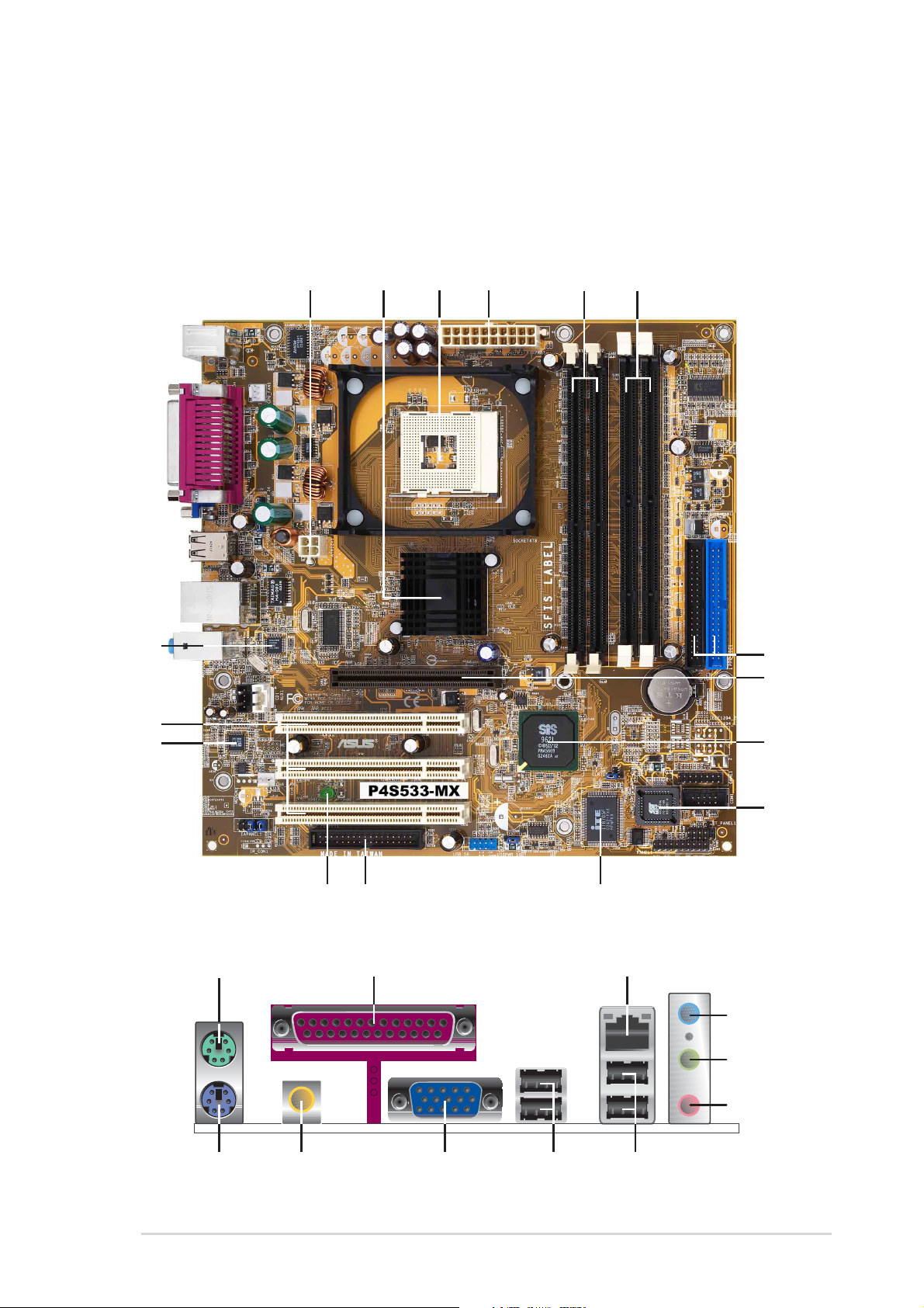
1.3 Motherboard components
34
1
2
0
17
0
1
2
18 19
Before you install the motherboard, learn about its major components and
available features to facilitate the installation and future upgrades. Refer to the
succeeding pages for the component descriptions.
5 6
16
15
14
13
12
7
8
9
1
11
2
2
2
27 24
2526
ASUS P4S533-MX motherboard user guide
23
1-3

1
A TX 12V connector. This power connector connects the 4-pin 12V plug from
the ATX 12V power supply.
2
North bridge controller . This SiS651 controller integrates a high
performance host interface for the Intel Pentium 4 processor, a memory
controller and SiS MuTIOL technology.
3
CPU socket. A 478-pin surface mount, Zero Insertion Force (ZIF) socket for
the Intel
®
Pentium® 4 Processor, with 533/400MHz system bus that allows
4.2GB/s and 3.2GB/s data transfer rates, respectively.
4
A TX power connector. This 20-pin connector connects to an ATX +12V
power supply . The power supply must have at least 1A on the +5V standby
lead (+5VSB).
5
DDR DIMM sockets. These two 184-pin DIMM sockets support up to 2GB
system memory using unbuffered non-ECC PC2700/PC2100/PC1600 DDR
DIMMs.
6
SDRAM DIMM sockets. These two 168-pin DIMM sockets support up to 2GB
system memory using unbuffered non-ECC PC133/PC100 SDRAM DIMMs.
7
IDE connectors. These dual-channel bus master IDE connectors support
Ultra DMA133/100/66, PIO Modes 3 & 4 IDE devices. Both the primary (blue)
and secondary (black) connectors are slotted to prevent incorrect insertion of
the IDE ribbon cable.
8
9
10
11
12
13
AGP slot. This Accelerated Graphics Port (AGP) slot supports 1.5V AGP4X
mode graphics cards for 3D graphical applications.
South bridge controller. Referred to as the SiS962L MuTIOL Media I/O,
this controller integrates the audio controller with AC’97 Interface, Ethernet
MAC, Dual Universal Serial Bus Host controllers, IDE Master/Slave
controllers, and the MuTIOL Connect to PCI Bridge.
Flash ROM. This 2Mb firmware contains the programmable BIOS program.
Super I/O controller. This Low Pin Count (LPC) interface provides the
commonly used Super I/O functionality . The chipset supports a highperformance floppy disk controller for a 360K/720K/1.44M/2.88M floppy disk
drive, a multi-mode parallel port, two standard compatible UARTs, and a Flash
ROM interface.
Floppy disk connector . This connector accommodates the provided ribbon
cable for the floppy disk drive. One side of the connector is slotted to prevent
incorrect insertion of the floppy disk cable.
Standby power LED. This LED lights up if there is a standby power on the
motherboard. This LED acts as a reminder to turn off the system power before
plugging or unplugging devices.
1-4
14
Audio CODEC. The ADI AD1980 is an AC’97 CODEC that allows 6-channel
audio playback. The audio CODEC provides six DAC channels for 5.1
surround sound, S/PDIF interface, AUX and Line In stereo inputs,
integrated headphone amplifier, greater than 90dB dynamic range.
Chapter 1: Product introduction
15
PCI slots. These three 32-bit PCI 2.2 expansion slots support bus master
PCI cards like SCSI or LAN cards with 133MB/s maximum throughput.
16
17
18
19
20
21
22
LAN PHY. The SiS 962L integrated 10/100Mbps Fast Ethernet with
Realtek external PHY supports your local area networking needs.
PS/2 mouse port. This green 6-pin connector is for a PS/2 mouse.
Parallel port. This 25-pin port connects a parallel printer, a scanner, or other
devices.
RJ-45 port. This port allows connection to a Local Area Network (LAN)
through a network hub. (on LAN models only)
Line In jack. This Line In (light blue) jack connects a tape player or other
audio sources. In 6-channel mode, the function of this jack becomes Bass/
Center .
Line Out jack. This Line Out (lime) jack connects a headphone or a
speaker . In 6-channel mode, the function of this jack becomes Front
Speaker Out.
Microphone jack. This Mic (pink) jack connects a microphone. In 6-channel
mode, the function of this jack becomes Rear Speaker Out.
The functions of the Line Out (lime), Line In (blue) and Microphone (pink) jacks
change when you select the 6-channel audio configuration as shown in the
following table:
Audio 2, 4 or 6-channel configuration
Headphone/
2-Speaker 4-Speaker 6-Speaker
Light Blue Line In Line In Bass/Center
Lime Line Out Front Speaker Out Front Speaker Out
Pink Mic In Rear Speaker Out Rear Speaker Out
Windows 98SE only supports 4 channel speaker setting.
23
24
25
26
27
USB 2.0 ports 3 and 4. These two 4-pin Universal Serial Bus (USB) ports
are available for connecting USB 2.0 devices.
USB 2.0 ports 1 and 2. These two 4-pin Universal Serial Bus (USB) ports
are available for connecting USB 2.0 devices.
VGA port. This 15-pin VGA port connects to a VGA monitor.
S/PDIF port. This port is for S/PDIF digital audio output devices.
PS/2 keyboard port. This purple connector is for a PS/2 keyboard.
ASUS P4S533-MX motherboard user guide
1-5

1.4 Special Features
1.4.1 Product highlights
Latest processor technology
The P4S533-MX motherboard supports the latest Intel® Pentium® 4 Processor via a
478-pin surface mount ZIF socket. The Pentium 4 processor with 512KB L2 cache on
0.13 micron process includes a 533/400 MHz system bus and features the new
Hyper-Threading technology and FMB2 power design that allow up to 3.0+ GHz
core frequencies for up to 4.2GB/s data transfer rates.
SDRAM and DDRAM Combo
P4S533-MX has two DDR sockets and two SDR sockets that support up to 2GB
non-ECC PC2700/2100/PC1600 or PC133/PC100 SDRAM DIMMs.
ASUS EZ Flash
With ASUS EZ Flash, you can update BIOS before entering operating system. No
more DOS-based flash utility and bootable diskette required.
(page 2-2)
C.P.R. (CPU Parameter Recall)
(page 1-10)
(page 1-12)
(page 1-15)
When the system hangs due to overclocking failure, there is no need to open the
case to clear the CMOS data. Simply restart the system and the BIOS will
automatically restore the CPU default setting for each parameter.
CrashFree BIOS
CrashFree BIOS allows users to restore BIOS data from a floppy diskette even
when BIOS code and data are corrupted during upgrade or invaded by a virus.
Unlike other competing vendors’ products, ASUS motherboards now enable users
to enjoy this protection feature without the need to pay for an optional ROM.
(page 2-7)
Powerful Integrated Graphics
The P4S533-MX delivers powerful integrated 2D and 3D graphics performance for
functionality and value.
SoundMAX Digital Audio System
The SoundMax Digital Audio System is the industry’s highest performance and
most reliable audio solution for business professionals, audiophiles, musicians,
and gamers. SoundMAX Digital Audio System can output 5.1 channel surround
and features state-of-the-art DLS2 MIDI synthesizer with Yamaha DLSbyXG sound
set, 5.1 Virtual Theater™ and supports all major game audio technologies
including Microsoft DirectX™8.0, Microsoft DirectSound 3D™, A3D, MacroFX,
ZoomFX, MultiDrive 5.1 and EAX.
(page 3-3)
1-6
Chapter 1: Product introduction
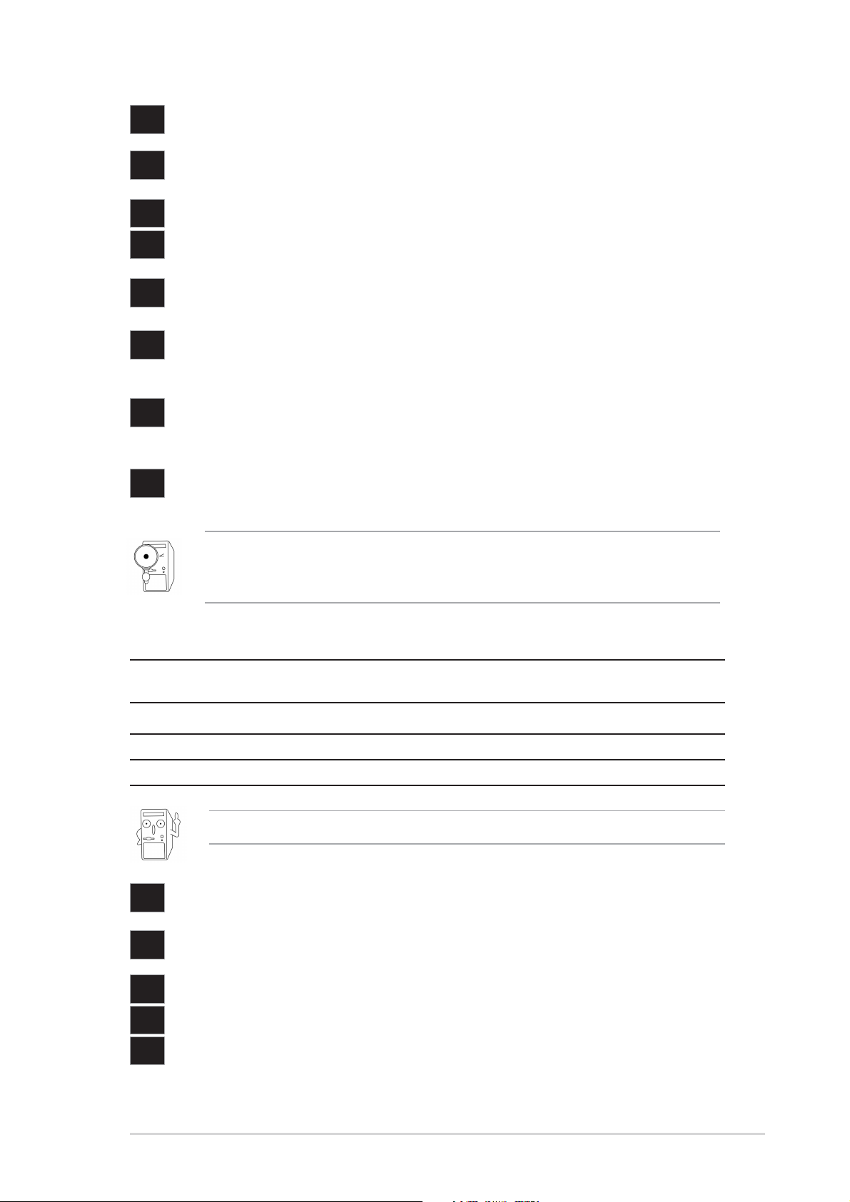
1.5 Motherboard layout
®
24.4cm (9.6in)
PS/2KBMS
T: Mouse
B: Keyboard
SPDIF1
VGA1
USB20_12
Bottom:
USB3
USB4
Top:Line In
Center:Line Out
Below:Mic In
CD1
Audio
Codec
CHA_FAN1
FP_AUDIO1
PARALLEL PORT
Top:
RJ-45
USBPWR_34
USBPWR_12
CPU_FAN1
AUX1
MDC1
SB_PWR1
ATX12V1
SiS651
HOST/
Memory
Controller
Accelerated Graphics Port
(AGP)
PCI Slot 1
PCI Slot 2
P4S533-MX
PCI Slot 3
FLOPPY1
ATX Power Connector
USBPWR_56
USB_56
Socket 478
SiS962L
MuTLOL
Media
I/0
SEC_IDE1
PRI_IDE1
DDR DIMM2 (64/72 bit, 184-pin module)
DDR DIMM1 (64/72 bit, 184-pin module)
2 3
01
CLRTC1
I/O
Super
DIMM Socket 1 (64/72-bit, 168-pin module)
DIMM Socket 1 (64/72-bit, 168-pin module)
23
01
CR2032 3V
Lithium Cell
CMOS Power
GAME1
2Mbit
Flash
BIOS
COM1
PANEL1
24.4cm (9.6in)
ASUS P4S533-MX motherboard user guide
1-7
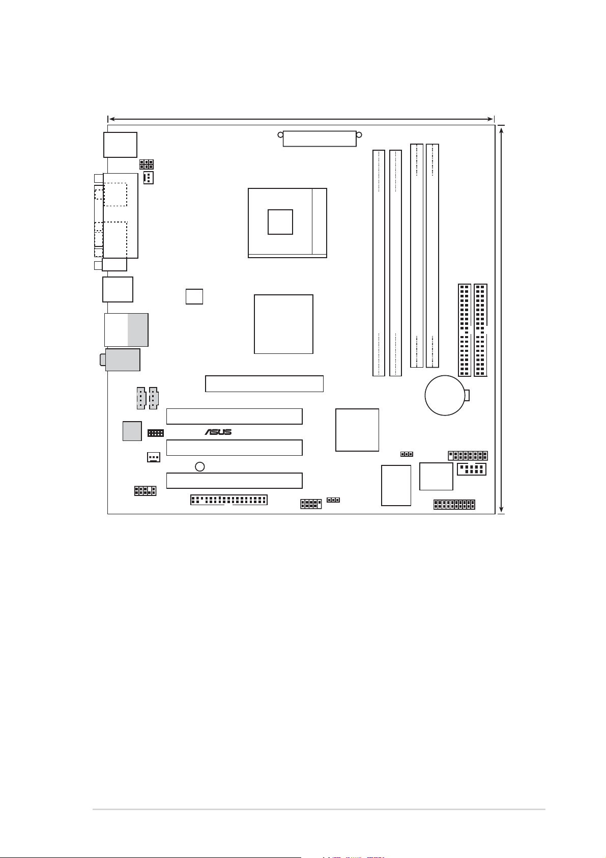
1.6 Before you proceed
®
d
Take note of the following precautions before you install motherboard components
or change any motherboard settings.
1. Unplug the power cord from the wall socket before touching any
component.
2. Use a grounded wrist strap or touch a safely grounded object or to a metal
object, such as the power supply case, before handling components to
avoid damaging them due to static electricity.
3. Hold components by the edges to avoid touching the ICs on them.
4. Whenever you uninstall any component, place it on a grounded antistatic
pad or in the bag that came with the component.
5. Before you install or remove any component, ensure that the ATX
power supply is switched off or the power cord is detached from the
power supply. Failure to do so may cause severe damage to the
motherboard, peripherals, and/or components.
When lit, the green LED (SB_PWR1) indicates that the system is ON, in sleep
mode, or in soft-off mode, a reminder that you should shut down the system and
unplug the power cable before removing or plugging in any motherboard
component.
SB_PWR1
P4S533-MX
ON OFF
P4S533-MX Onboard LED
Standby
Power
Powere
Off
Install only 1.5V AGP cards on this motherboard!
1-8
Chapter 1: Product introduction
1.7 Motherboard installation
Before you install the motherboard, study the configuration of your chassis to
ensure that the motherboard fits into it. The motherboard uses the micro-ATX form
factor that measures 9.6 inches x 9.6 inches (24.5 cm x 24.5 cm).
Make sure to unplug the power cord before installing or removing the
motherboard. Failure to do so may cause you physical injury and damage
motherboard components.
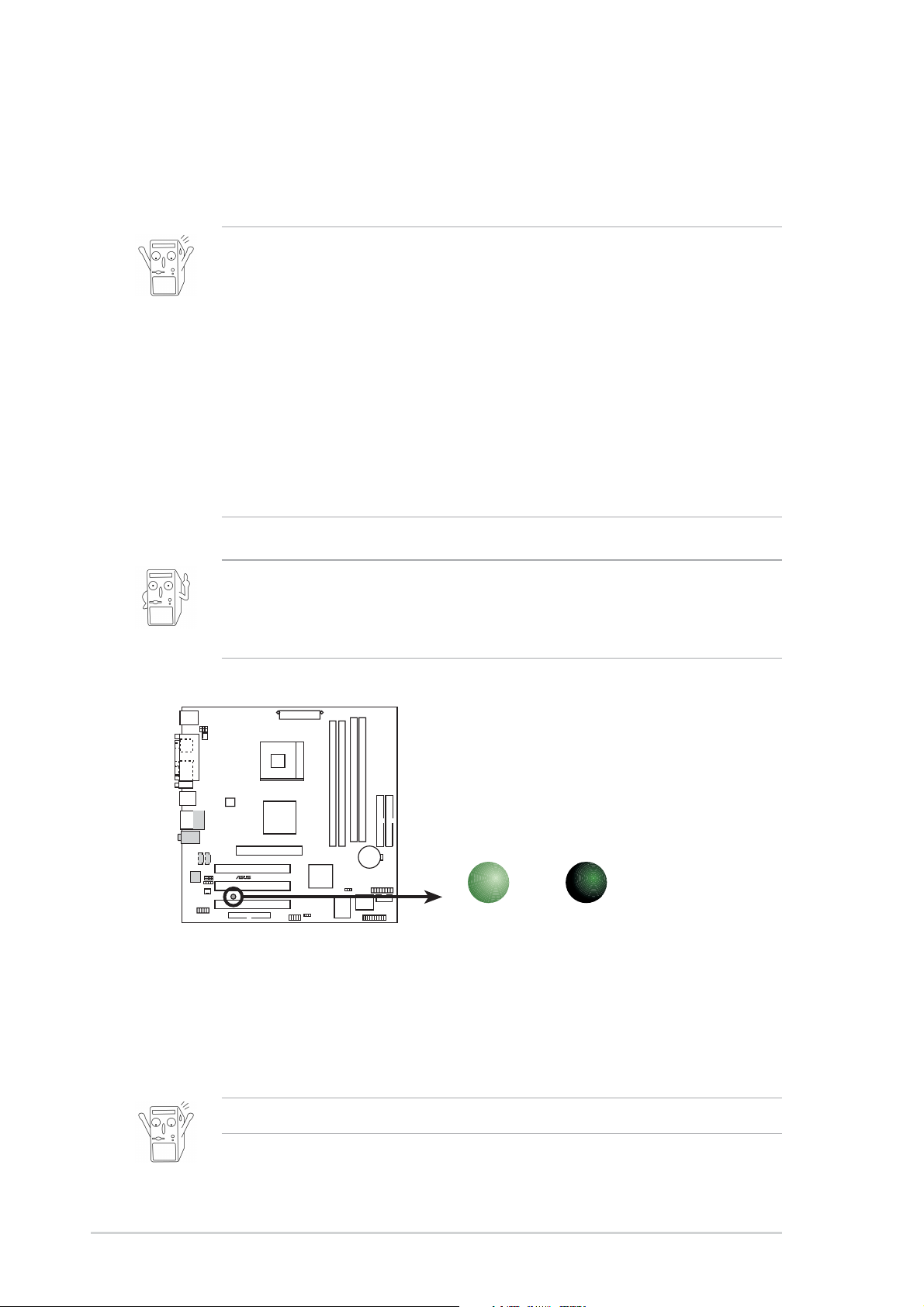
1.7.1 Placement direction
When installing the motherboard, make sure that you place it into the chassis in
the correct orientation. The edge with external ports goes to the rear part of the
chassis as indicated in the image below.
1.7.2 Screw holes
Place eight (8) screws into the holes indicated by circles to secure the
motherboard to the chassis.
Do not overtighten the screws! Doing so may damage the motherboard.
Place this side towards
the rear of the chassis
ASUS P4S533-MX motherboard user guide
1-9
1.8 Central Processing Unit (CPU)
1.8.1 Overview
The motherboard comes with a surface mount 478-pin Zero Insertion Force (ZIF)
socket. The socket is designed for the Intel® Pentium® 4 Processor in the 478-pin
package with 512/256KB L2 cache on 0.13 micron process. This processor
supports 533/400MHz front side bus (FSB), and allows data transfer rates of
4.2GB/s and 3.2GB/s.
Note in the illustration that the CPU has a
gold triangular mark on one corner. This
mark indicates the processor Pin 1 that
should match a specific corner of the
CPU socket.
Incorrect installation of the CPU into the socket may bend the pins and
severely damage the CPU!
Notes on Intel® Hyper-Threading Technology
1. This motherboard supports Intel Pentium 4 CPUs with Hyper-Threading
Technology. (since PCB R2.00 or later versions)
2. Hyper-Threading Technology is supported under Windows XP and Linux
2.4.x (kernel) and later versions only. Under Linux, use the Hyper-Threading
compliler to compile the code. If you are using any other operating systems,
disable the Hyper-Threading Techonology item in BIOS to ensure system
stability and performance.
Gold Mark
3. It is recommended that you install WinXP Service Pack 1.
4. Make sure to enable the Hyper-Threading Technology item in BIOS before
installing a supported operating system.
5. For more information on Hyper-Threading Technology, visit www.intel.com/
info/hyperthreading.
To use the Hyper-Threading Technology on this motherboard:
1. Buy an Intel Pentium 4 CPU that supports Hyper-Threading Technology. Install
the CPU.
2. Power up the system and enter BIOS Setup (see Chapter 2). Under the Boot
Menu, make sure that the item Hyper-Threading Technology is set to
Enabled. The item appears only if you installed a CPU that supports HyperThreading Techonology.
3. Reboot the computer.
1-10
Chapter 1: Product introduction
 Loading...