

ASUS M2V-MX User Manual

Motherboard
M2V-MX
ii
Copyright © 2006 ASUSTeK COMPUTER INC. All Rights Reserved.
No part of this manual, including the products and software described in it, may be reproduced,
transmitted, transcribed, stored in a retrieval system, or translated into any language in any form
or by any means, except documentation kept by the purchaser for backup purposes, without the
express written permission of ASUSTeK COMPUTER INC. (“ASUS”).
Product warranty or service will not be extended if: (1) the product is repaired, modied or
altered, unless such repair, modication of alteration is authorized in writing by ASUS; or (2) the
serial number of the product is defaced or missing.
ASUS PROVIDES THIS MANUAL “AS IS” WITHOUT WARRANTY OF ANY KIND, EITHER EXPRESS
OR IMPLIED, INCLUDING BUT NOT LIMITED TO THE IMPLIED WARRANTIES OR CONDITIONS OF
MERCHANTABILITY OR FITNESS FOR A PARTICULAR PURPOSE. IN NO EVENT SHALL ASUS,
ITS DIRECTORS, OFFICERS, EMPLOYEES OR AGENTS BE LIABLE FOR ANY INDIRECT, SPECIAL,
INCIDENTAL, OR CONSEQUENTIAL DAMAGES (INCLUDING DAMAGES FOR LOSS OF PROFITS, LOSS
OF BUSINESS, LOSS OF USE OR DATA, INTERRUPTION OF BUSINESS AND THE LIKE), EVEN IF ASUS
HAS BEEN ADVISED OF THE POSSIBILITY OF SUCH DAMAGES ARISING FROM ANY DEFECT OR
ERROR IN THIS MANUAL OR PRODUCT.
SPECIFICATIONS AND INFORMATION CONTAINED IN THIS MANUAL ARE FURNISHED FOR
INFORMATIONAL USE ONLY, AND ARE SUBJECT TO CHANGE AT ANY TIME WITHOUT NOTICE, AND
SHOULD NOT BE CONSTRUED AS A COMMITMENT BY ASUS. ASUS ASSUMES NO RESPONSIBILITY
OR LIABILITY FOR ANY ERRORS OR INACCURACIES THAT MAY APPEAR IN THIS MANUAL,
INCLUDING THE PRODUCTS AND SOFTWARE DESCRIBED IN IT.
Products and corporate names appearing in this manual may or may not be registered
trademarks or copyrights of their respective companies, and are used only for identication or
explanation and to the owners’ benet, without intent to infringe.
E282 6
Firs t E diti o n V1
Sept e m b er 2 0 0 6

iii
Contents
Notices ................................................................................................ vi
Safety information ..............................................................................vii
M2V-MX specications summary ........................................................viii
Chapter 1: Product introduction
1.1 Welcome! .............................................................................. 1-2
1.2 Package contents .................................................................
1-2
1.3 Special features ....................................................................
1-2
1.3.1 Product highlights ...................................................
1-2
1.3.2 Innovative ASUS features ......................................
1-4
1.4 Before you proceed ..............................................................
1-5
1.5 Motherboard overview ..........................................................
1-6
1.5.1 Motherboard layout ................................................
1-6
1.5.2 Placement direction ................................................
1-7
1.5.3 Screw holes .............................................................
1-7
1.6 Central Processing Unit (CPU) ..............................................
1-8
1.6.1 Installing the CPU ....................................................
1-8
1.6.2 Installing the heatsink and fan ..............................
1-10
1.7 System memory ..................................................................
1-12
1.7.1 Overview ...............................................................
1-12
1.7.2 Memory congurations .........................................
1-12
1.7.3 DDR2 Qualied Vendoros List ...............................
1-13
1.7.4 Installing a DIMM ...................................................
1-16
1.7.5 Removing a DIMM ..................................................
1-16
1.8 Expansion slots ...................................................................
1-17
1.8.1 Installing an expansion card ..................................
1-17
1.8.2 Conguring an expansion card ..............................
1-17
1.8.3 PCI slots ................................................................
1-19
1.8.4 PCI Express x1 slot ...............................................
1-19
1.8.5 PCI Express x16 slot .............................................
1-19
1.9 Jumpers ..............................................................................
1-20
1.10 Connectors .........................................................................
1-22
1.10.1 Rear panel connectors ..........................................
1-22
1.10.2 Internal connectors ...............................................
1-23
iv
Contents
Chapter 2: BIOS setup
2.1 Managing and updating your BIOS ........................................ 2-2
2.1.1 Creating a bootable oppy disk ..............................
2-2
2.1.2 ASUS EZ Flash 2 utility ............................................
2-3
2.1.3 AFUDOS utility ........................................................
2-4
2.1.4 ASUS CrashFree BIOS 2 utility ................................
2-6
2.1.5 ASUS Update utility ................................................
2-8
2.2 BIOS setup program ............................................................
2-11
2.2.1 BIOS menu screen .................................................
2-12
2.2.2 Menu bar ...............................................................
2-12
2.2.3 Navigation keys .....................................................
2-12
2.2.4 Menu items ...........................................................
2-13
2.2.5 Sub-menu items ....................................................
2-13
2.2.6 Conguration elds ...............................................
2-13
2.2.7 Pop-up window ......................................................
2-13
2.2.8 Scroll bar ...............................................................
2-13
2.2.9 General help ..........................................................
2-13
2.3 Main menu ...........................................................................
2-14
2.3.1 System Time .........................................................
2-14
2.3.2 System Date .........................................................
2-14
2.3.3 Legacy Diskette A ...............................................
2-14
2.3.4 Primary and Secondary IDE Master/Slave ............
2-15
2.3.5 SATA1 and SATA2 ................................................
2-17
2.3.6 IDE Conguration ..................................................
2-18
2.3.7 System Information
............................................... 2-19
2.4 Advanced menu ..................................................................
2-20
2.4.1 JumperFree Conguration .....................................
2-20
2.4.2 USB Conguration .................................................
2-21
2.4.3 CPU Conguration .................................................
2-22
2.4.4 Chipset ..................................................................
2-26
2.4.5 Onboard Devices Conguration .............................
2-27
2.4.6 PCI PnP ..................................................................
2-29
2.5 Power menu ........................................................................
2-30
2.5.1 Suspend Mode .......................................................
2-30
2.5.2 ACPI 2.0 Support ..................................................
2-30
v
Contents
2.5.3 ACPI APIC Support ................................................ 2-30
2.5.4 APM Conguration ................................................
2-31
2.5.5 Hardware Monitor ..................................................
2-32
2.6 Boot menu ..........................................................................
2-34
2.6.1 Boot Device Priority ..............................................
2-34
2.6.2 Boot Settings Conguration .................................
2-35
2.6.3 Security .................................................................
2-36
2.7 Tools menu .........................................................................
2-40
2.7.1 ASUS EZ Flash 2 ....................................................
2-40
2.8 Exit menu ............................................................................
2-41
Chapter 3: Software support
3.1 Installing an operating system .............................................. 3-2
3.2 Support CD information ........................................................
3-2
3.2.1 Running the support CD ..........................................
3-2
3.2.2 Drivers menu ...........................................................
3-3
3.2.3 Utilities menu ..........................................................
3-4
3.2.4 Make Disk menu ......................................................
3-5
3.2.5 ASUS Contact information ......................................
3-6
vi
Notices
Fed er al Co mm un ica ti on s C om mi ssi on S tat em en t
This device complies with Part 15 of the FCC Rules. Operation is subject to
the following two conditions:
•
This device may not cause harmful interference, and
•
This device must accept any interference received including
interference that may cause undesired operation.
This equipment has been tested and found to comply with the limits for a
Class B digital device, pursuant to Part 15 of the FCC Rules. These limits
are designed to provide reasonable protection against harmful interference
in a residential installation. This equipment generates, uses and can radiate
radio frequency energy and, if not installed and used in accordance with
manufacturer’s instructions, may cause harmful interference to radio
communications. However, there is no guarantee that interference will
not occur in a particular installation. If this equipment does cause harmful
interference to radio or television reception, which can be determined by
turning the equipment off and on, the user is encouraged to try to correct
the interference by one or more of the following measures:
•
Reorient or relocate the receiving antenna.
•
Increase the separation between the equipment and receiver.
•
Connect the equipment to an outlet on a circuit different from that to
which the receiver is connected.
•
Consult the dealer or an experienced radio/TV technician for help.
Can ad ia n D ep ar tme nt o f C om mu nic at io ns St at eme nt
This digital apparatus does not exceed the Class B limits for radio noise
emissions from digital apparatus set out in the Radio Interference
Regulations of the Canadian Department of Communications.
This class B digital apparatus complies with Canadian
ICES-003.
The use of shielded cables for connection of the monitor to the graphics
card is required to assure compliance with FCC regulations. Changes
or modications to this unit not expressly approved by the party
responsible for compliance could void the user’s authority to operate
this equipment.
vii
Safety information
Ele c tr i cal sa f ety
•
To prevent electrical shock hazard, disconnect the power cable from
the electrical outlet before relocating the system.
•
When adding or removing devices to or from the system, ensure that
the power cables for the devices are unplugged before the signal cables
are connected. If possible, disconnect all power cables from the existing
system before you add a device.
•
Before connecting or removing signal cables from the motherboard,
ensure that all power cables are unplugged.
•
Seek professional assistance before using an adapter or extension cord.
These devices could interrupt the grounding circuit.
•
Make sure that your power supply is set to the correct voltage in your
area. If you are not sure about the voltage of the electrical outlet you
are using, contact your local power company.
•
If the power supply is broken, do not try to fix it by yourself. Contact a
qualified service technician or your retailer.
Ope r at i on s af e ty
•
Before installing the motherboard and adding devices on it, carefully
read all the manuals that came with the package.
•
Before using the product, make sure all cables are correctly connected
and the power cables are not damaged. If you detect any damage,
contact your dealer immediately.
•
To avoid short circuits, keep paper clips, screws, and staples away from
connectors, slots, sockets and circuitry.
•
Avoid dust, humidity, and temperature extremes. Do not place the
product in any area where it may become wet.
•
Place the product on a stable surface.
•
If you encounter technical problems with the product, contact a
qualified service technician or your retailer.
The symbol of the crossed out wheeled bin indicates that the product
(electrical and electronic equipment) should not be placed in municipal
waste. Check local regulations for disposal of electronic products.
viii
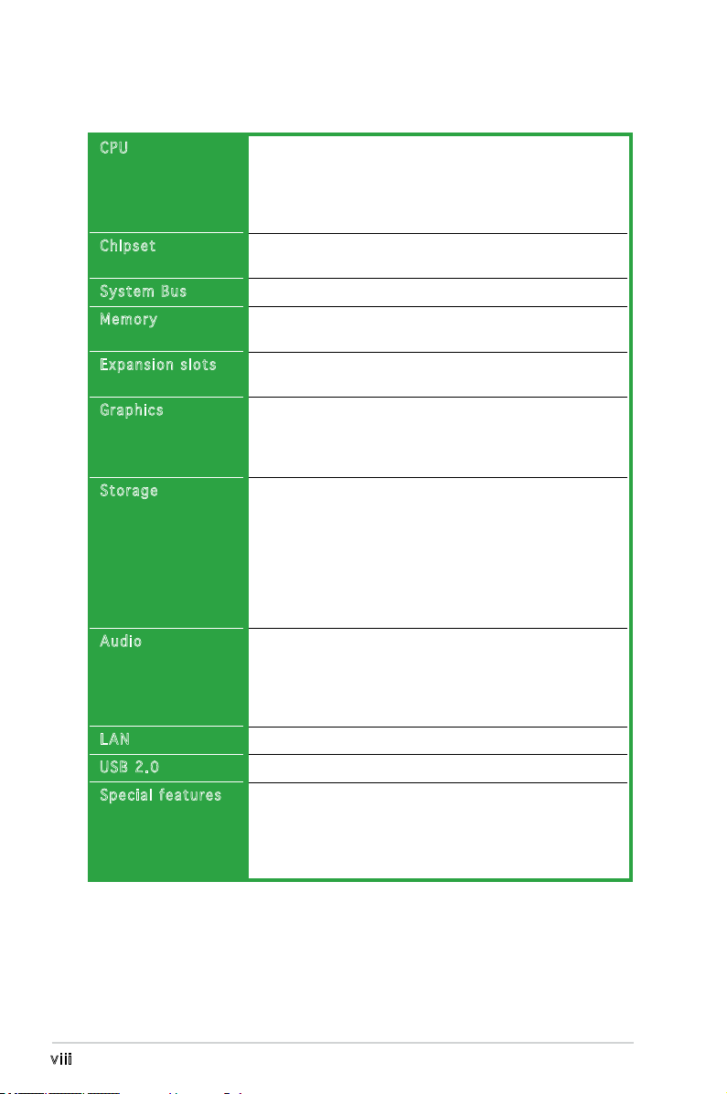
M2V-MX specications summary
(continued on the next page)
CPU
Chipset
System Bus
Memory
Expansion slots
Graphics
Storage
Audio
LAN
USB 2.0
Special features
Support AMD socket AM2 for AMD Athlon™ 64 FX/
Athlon™ 64 X2/Athlon™ 64/AMD Sempron™ processor
AMD64 architecture enables simultaneous 32-bit and
64-bit computing
Supports AMD Cool ‘n’ Quiet™ Technology
VIA® K8M890
VIA® VT8237A
2000 MT/s
2 x 240-pin DIMM sockets support up to 4 GB of ECC/
non-ECC unbufferred DDR2 800/667/533 MHz DIMMs
1 x PCI Express™ x16 slot
2 x PCI slots
Integrated in the VIA® DeltaChrome Graphics
Processing Unit (GPU)
Supports a maximum of 256MB shared memory
Supports Microsoft® DX9
VIA® VT8237A supports:
- 2 x Ultra DMA 133/100/66/33
- 2 x Serial ATA 3.0 Gb/s hard disk drives supporting
RAID 0, RAID 1, and JBOD congurations
JMicron® JMB363 controller supports:
- 2 x Serial ATA 3.0 Gb/s hard disk drives
supporting RAID 0, and RAID 1 conguration
Realtek® ALC883 Azalia 6-channel audio CODEC
Supports Jack-Sensing and Enumeration Technology
Supports Multi-Streaming Technology
Supports Jack-Retasking Technology
S/PDIF out support
Realtek® RTL8100C 10/100 LAN
Supports up to 8 USB 2.0 ports
ASUS EZ Flash 2
ASUS CrashFree BIOS 2
ASUS MyLogo™
ASUS C.P.R. (CPU Parameter Recall)
ASUS Q-Fan2
ix
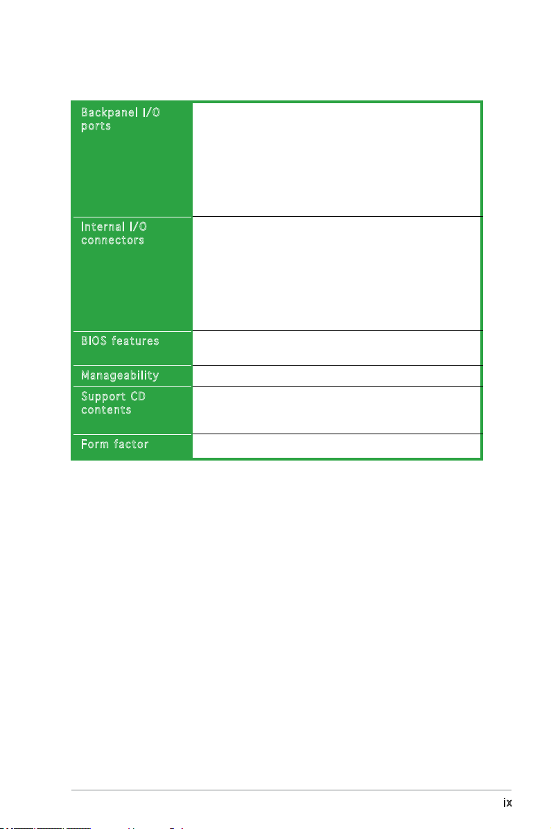
M2V-MX specications summary
Backpanel I/O
ports
Internal I/O
connectors
BIOS features
Manageability
Support CD
contents
Form factor
1 x Parallel
1 x PS/2 keyboard
1 x PS/2 mouse
1 x 6-channel Audio I/O
1 x RJ45 port
1 x VGA port
4 x USB
1 x Serial port
2 x USB connector supports additional 4 USB ports
24-pin ATX power connector
4-pin ATX 12V power connector
1 x S/PDIF out connector
1 x CD audio-in connector
1 x CPU/ 1 x Chassis fan connectors
1 x Front Panel AC’97 audio connector
10-pin system panel connector
4 Mb Flash ROM, AMI BIOS, PnP, DMI2.0, WfM2.0, SM
BIOS 2.3
WfM 2.0, DMI 2.0, WOL by PME, PXE, RPL, WOR by PME
Drivers
Anti-virus software
ASUS LiveUpdate
Micro-ATX form factor: 9.6 in x 8.6 in
*Specications are subject to change without notice.

x

1
Product
introduction
This chapter describes the motherboard
features and the new technologies
it supports.
1-2 Chapter 1: Product introduction
1.1 Welcome!
Than k y ou f o r buyi n g an A S U S® M2V - M X mot h e r boar d !
The motherboard delivers a host of new features and latest technologies,
making it another standout in the long line of ASUS quality motherboards!
Before you start installing the motherboard, and hardware devices on it,
check the items in your package with the list below.
If any of the above items is damaged or missing, contact your retailer.
1.2 Package contents
Check your motherboard package for the following items.
Motherboard ASUS M2V-MX motherboard
Cables 1 x Serial ATA signal cables
1 x Serial ATA power cable
1 x Ultra DMA 133/100/66 cable
1 x Floppy disk drive cable
Accessories I/O shield
Application CD ASUS motherboard support CD
Documentation User guide
1.3 Special features
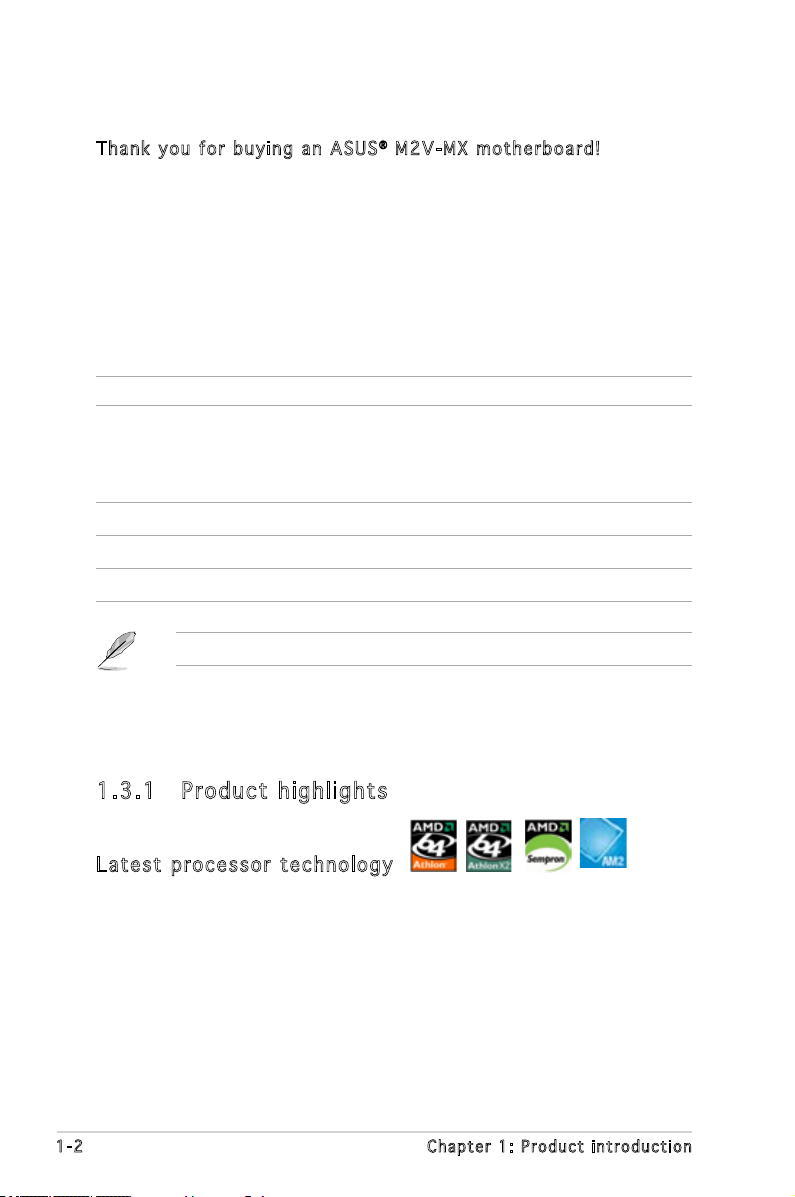
1.3 .1 Pro du ct hi gh li ght s
Lat e st pro c es s or t ec h nol o gy
The motherboard supports AMD socket AM2 single-core Athlon 64/
Sempron and dual-core Athlon 64FX/ Athlon 64 X2 processors with
2MB/1MB/512KB L2 cache, which is based on 64-bit architecture. It
features 2000/1600 MT/s HyperTransport Bus, dual-channel un-buffered
DDR2 667 memory support and AMD Cool ‘n’ Quiet Technology. See page
1-8 for details.
ASUS M2V-MX 1-3
DDR 2 80 0MH z me m or y su p po r t
DDR2 is the next generation memory technology to replace the current
DDR. With the highest speed up to 800MHz, DDR2 memory provides great
performance for 3D graphics and other memory demanding applications.
PCI Ex p res s ™ i nte r fa c e
The motherboard fully supports PCI Express, the latest I/O interconnect
technology that speeds up the PCI bus. PCI Express features point-to-point
serial interconnections between devices and allows higher clockspeeds by
carrying data in packets. This high speed interface is software compatible
with existing PCI specications. See page 1-19 for details.
USB 2.0 te c hno log y
The motherboard implements the Universal Serial Bus (USB) 2.0
specication, dramatically increasing the connection speed from the
12 Mbps bandwidth on USB 1.1 to a fast 480 Mbps on USB 2.0. USB 2.0 is
backward compatible with USB 1.1. See pages 1-23 and 1-28 for details.
10/ 1 00 M bp s LA N
Easy connectivity to your network or broadband connection with the
onboard LAN port, lets you take gaming online without buying expensive
additional LAN cards. See pages 1-22 for details.
AMD Co o l ‘ n ’ Q uie t T e chn o lo g y
The motherboard supports the AMD Cool ‘n’ Quiet Technology, which
monitors system operation and automatically adjusts CPU voltage and
frequency for a cool and quiet operating environment.
1-4 Chapter 1: Product introduction
1.3 .2 Inn ov at ive A SU S f ea tu res
ASU S E Z Fl a sh 2
EZ Flash 2 is a user-friendly BIOS update utility. Simply press the predened
hotkey to launch the utility and update the BIOS without entering the OS.
Update your BIOS easily without preparing a bootable diskette or using an
OS-based ash utility. See page 2-3 for details.
Cra s hF r ee B IO S 2
This feature allows you to restore the original BIOS data from the support
CD in case when the BIOS codes and data are corrupted. This protection
eliminates the need to buy a replacement ROM chip. See page 2-6 for details.
ASU S Q - Fan 2 te chn o log y
The ASUS Q-Fan2 technology smartly adjusts both the CPU and chassis fan
speeds according to the system loading to ensure quiet, cool, and efcient
operation. See page 2-33 for details.
ASU S M y Log o ™
This new feature present in the motherboard allows you to personalize and
add styles to your system with customizable boot logos. See page 2-35 for
details.
C.P . R. (CP U P a ram e te r Re c al l )
The C.P.R. feature of the motherboard BIOS allows automatic re-setting to
the BIOS default settings in case the system hangs due to overclocking.
When the system hangs due to overclocking, C.P.R. eliminates the need
to open the system chassis and clear the RTC data. Simply shut down and
reboot the system, and the BIOS automatically restores the CPU default
setting for each parameter.
Due to chipset behavior, AC power off is required prior using C.P.R.
function.
ASUS M2V-MX 1-5
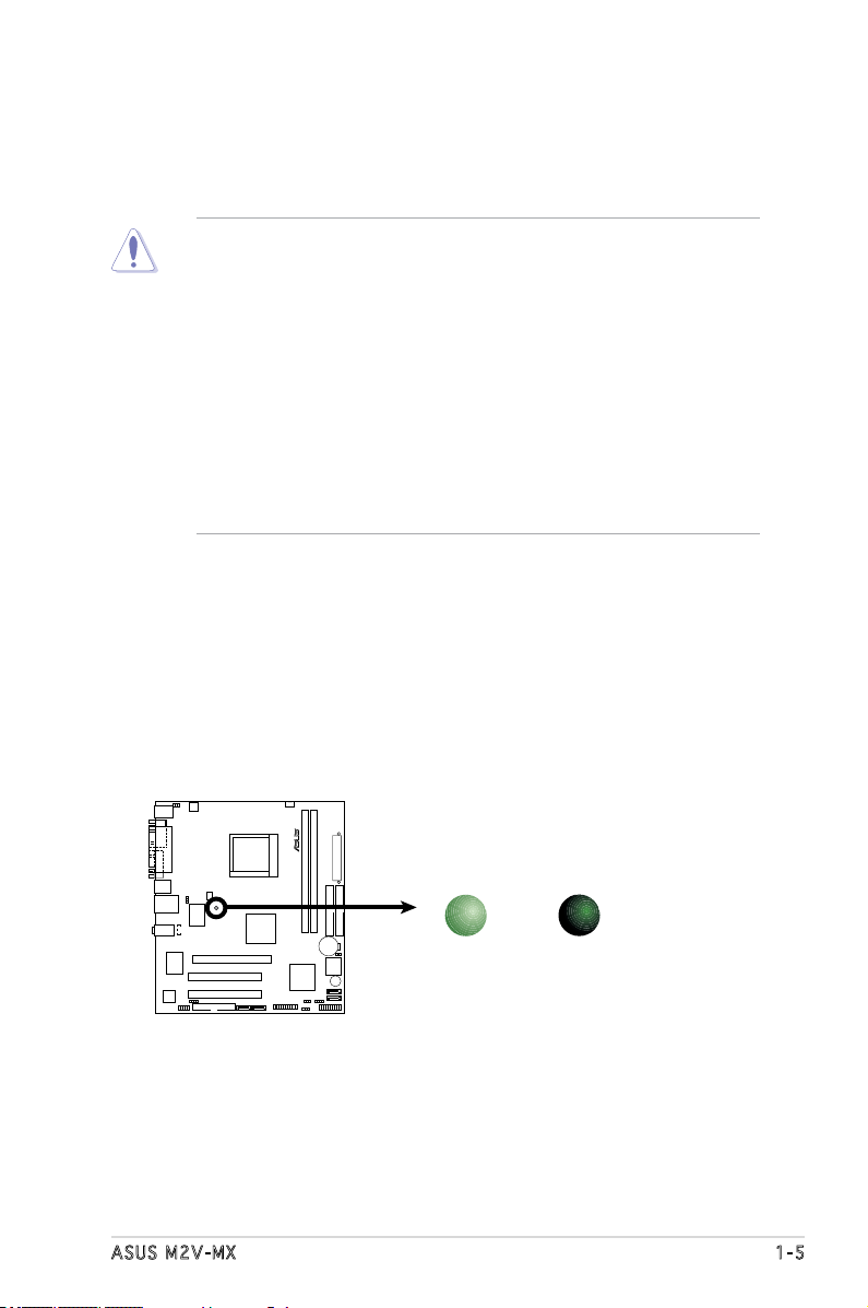
Onboard LED
The motherboard comes with a standby power LED that lights up to
indicate that the system is ON, in sleep mode, or in soft-off mode.
This is a reminder that you should shut down the system and unplug
the power cable before removing or plugging in any motherboard
component. The illustration below shows the location of the onboard
LED.
1.4 Before you proceed
Take note of the following precautions before you install motherboard
components or change any motherboard settings.
• Unplug the power cord from the wall socket before touching any
component.
• Use a grounded wrist strap or touch a safely grounded object or
a metal object, such as the power supply case, before handling
components to avoid damaging them due to static electricity
• Hold components by the edges to avoid touching the ICs on them.
• Whenever you uninstall any component, place it on a grounded
antistatic pad or in the bag that came with the component.
• Before you install or remove any component, ensure that the ATX
power supply is switched off or the power cord is detached from
the power supply. Failure to do so may cause severe damage to the
motherboard, peripherals, and/or components.
M2V-MX
R
M2V-MX Onboard LED
SB_PWR
ON
Standby
Power
OFF
Powered
Off
1-6 Chapter 1: Product introduction
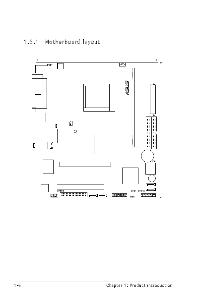
1.5 .1 Mot he rb oar d la you t
1.5 Motherboard overview
M2V-MX
21.8cm (8.6in)
24.5cm (9.6in
)
R
Socket M2
CPU_FAN
DDR2 DIMM_A1 (64 bit,240-pin module)
DDR2 DIMM_B1 (64 bit,240-pin module)
EATXPWR
PRI_IDE
SEC_IDE
CR2032 3V
Lithium Cell
CMOS Power
BIOS_WP
4Mb
BIOS
BUZZER
SATA1
SATA_E1 SATA_E2
SATA2
PANEL
CLRTC CHASSIS
USBPW5-8
USB78USB56
VIA
VT8237A
VIA
K8M890
PCI2
PCI1
PCIEX16
SPDIF_OUT
FLOPPY
AAFP
RTL8100C
ALC883
CHA_FAN
SB_PWR
LAN2_USB34
AUDIO
PARALLEL
POR
T
VGA COM1
PS/2KBMS
T: Mouse
B: Keyboard
USB12
ATX12V
KBPWR
CD
USBPW1-4
Super I/O
ASUS M2V-MX 1-7
M2V-MX
R
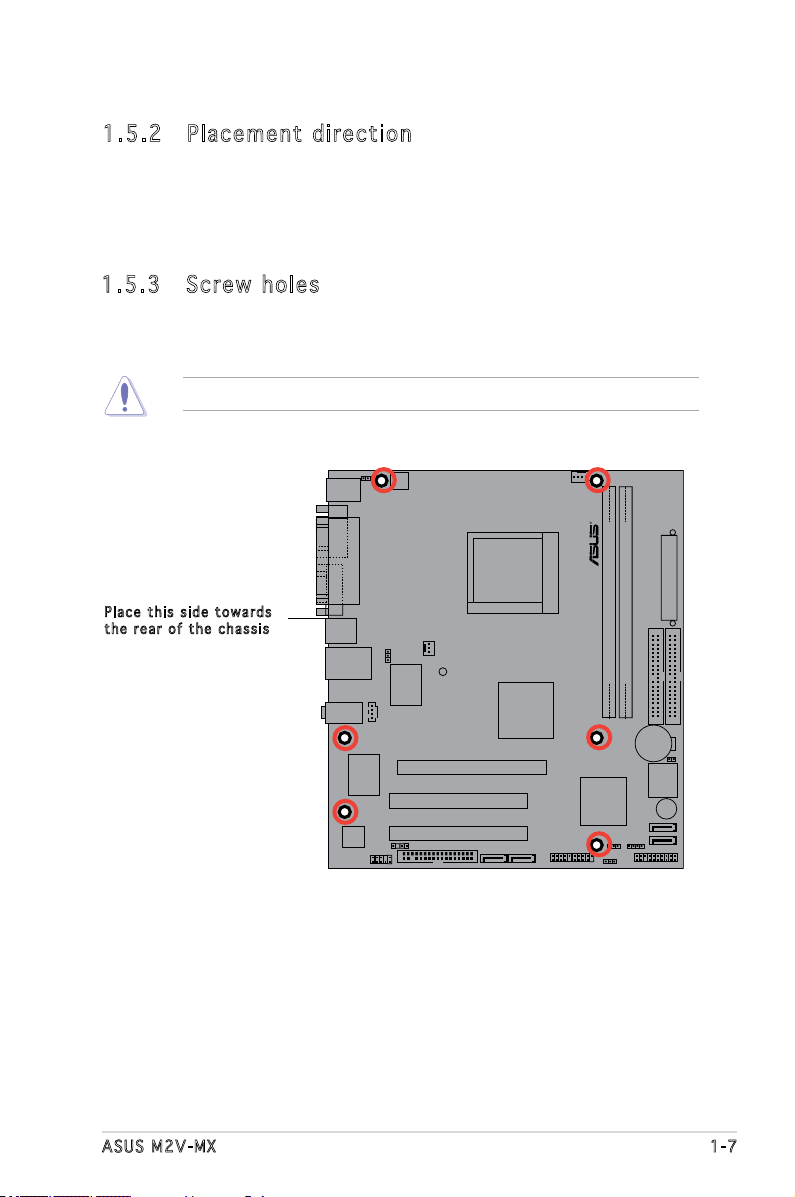
Do not overtighten the screws! Doing so can damage the motherboard.
1.5 .2 Pla ce me nt di re cti on
When installing the motherboard, make sure that you place it into the
chassis in the correct orientation. The edge with external ports goes to the
rear part of the chassis as indicated in the image below.
Pla c e this s i d e tow a r d s
the r e ar of t h e cha s s i s
1.5 .3 Scr ew h ole s
Place six (6) screws into the holes indicated by circles to secure the
motherboard to the chassis.

1-8 Chapter 1: Product introduction
1.6 Central Processing Unit (CPU)
The motherboard comes with a 940-pin AM2 socket designed for the
AMD Athlon™ 64 FX/Athlon™ 64 X2/AMD Athlon™ 64/AMD Sempron™
processor.
Make sure you use a CPU is designed for the AM2 socket. The CPU ts in
only one correct orientation. DO NOT force the CPU into the socket to
prevent bending the connectors on the socket and damaging the CPU!
1.6 . 1 I nst all i ng the CP U
To install a CPU.
1. Locate the CPU socket on the motherboard.
2. Unlock the socket by pressing the
lever sideways, then lift it up to a
90°-100° angle.
Make sure that the socket lever is lifted up to 90°-100° angle, otherwise
the CPU does not t in completely.
Soc k e t leve r
M2V-MX
R
M2V-MX CPU Socket M2
ASUS M2V-MX 1-9
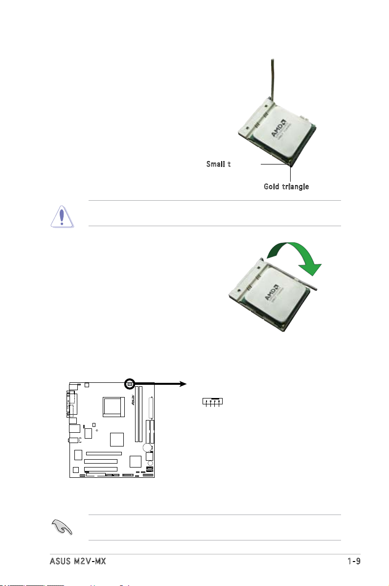
3. Position the CPU above the
socket such that the CPU corner
with the gold triangle matches
the socket corner with a small
triangle.
4. Carefully insert the CPU into the
socket until it ts in place.
The CPU ts only in one correct orientation. DO NOT force the CPU into
the socket to prevent bending the pins and damaging the CPU!
5. When the CPU is in place, push
down the socket lever to secure
the CPU. The lever clicks on the
side tab to indicate that it is
locked.
6. Install a CPU heatsink and fan
following the instructions that
came with the heatsink package.
Gol d t riang l e
Sma l l trian g l e
7. Connect the CPU fan cable to the CPU_FAN connector on the
motherboard.
Do not forget to connect the CPU fan connector! Hardware monitoring
errors can occur if you fail to plug this connector.
M2V-MX
R
M2V-MX CPU Fan Connector
CPU_FAN
GND
CPU FAN PWR
CPU FAN IN
CPU FAN PWM

1-10 Chapter 1: Product introduction
1.6 .2 Ins ta ll ing t he h e at si nk an d fa n
The AMD AMD Athlon™ 64 FX/ Athlon™ 64 X2/AMD Athlon™ 64/AMD
Sempron™ processor require a specially designed heatsink and fan assembly
to ensure optimum thermal condition and performance.
Follow these steps to install the CPU heatsink and fan.
1. Place the heatsink on top of the installed CPU, making sure that the
heatsink ts properly on the retention module base.
Ret e n t ion M o d u le Ba s e
CPU H e atsin k
CPU F a n
Ret e n t ion b r a c ket l o c kRet e n t ion b r a c ket
Make sure that you use only qualied heatsink and fan assembly.
• The retention module base is already installed on the motherboard
upon purchase.
• You do not have to remove the retention module base when
installing the CPU or installing other motherboard components.
• If you purchased a separate CPU heatsink and fan assembly, make
sure that a Thermal Interface Material is properly applied to the CPU
heatsink or CPU before you install the heatsink and fan assembly.
Your boxed CPU heatsink and fan assembly should come with installation
instructions for the CPU, heatsink, and the retention mechanism. If the
instructions in this section do not match the CPU documentation, follow
the latter.
ASUS M2V-MX 1-11
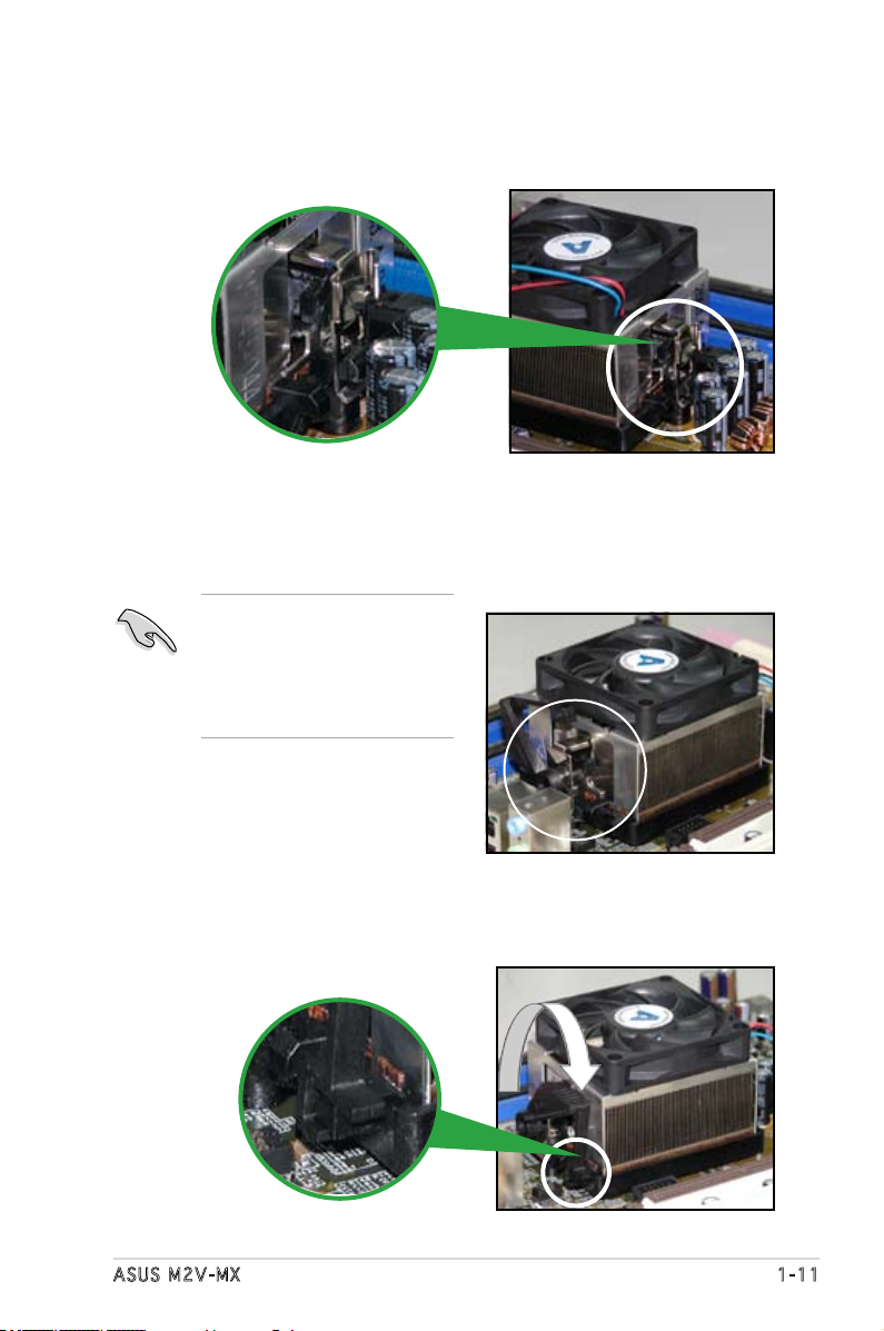
2. Attach one end of the retention bracket to the retention module base.
3. Align the other end of the retention bracket (near the retention
bracket lock) to the retention module base. A clicking sound denotes
that the retention bracket is in place.
4. Push down the retention bracket lock on the retention mechanism to
secure the heatsink and fan to the module base.
Make sure that the fan and
heatsink assembly perfectly
ts the retention mechanism
module base; otherwise, you
cannot snap the retention
bracket in place.
1-12 Chapter 1: Product introduction
1.7 .2 Mem or y con fi gu rat io ns
You may install 256 MB, 512 MB, 1 GB, and 2 GB unbuffered non-ECC DDR2
DIMMs into the DIMM sockets.
1.7 System memory
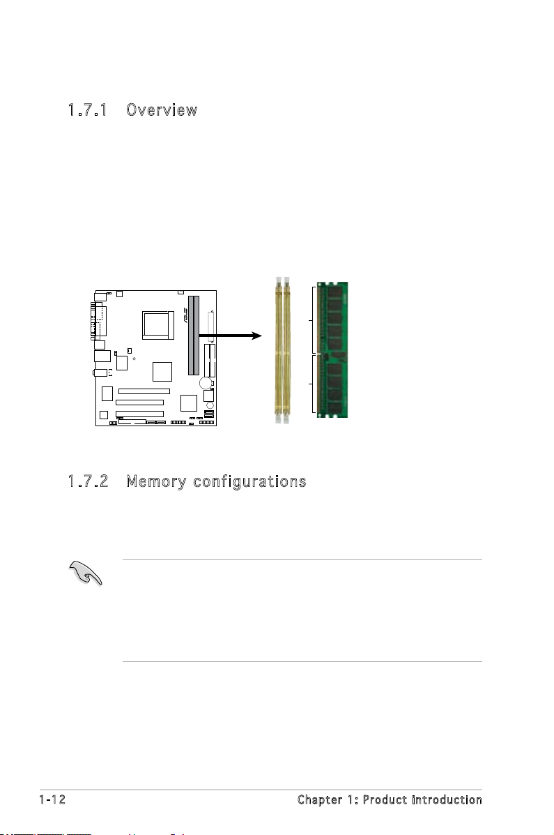
1.7 .1 Ove rv ie w
The motherboard comes with two Double Data Rate 2 (DDR2) Dual Inline
Memory Modules (DIMM) sockets.
A DDR2 module has the same physical dimensions as a DDR DIMM but has
a 240-pin footprint compared to the 184-pin DDR DIMM. DDR2 DIMMs are
notched differently to prevent installation on a DDR DIMM socket.
The gure illustrates the location of the DDR2 DIMM sockets:
• Due to chipset resource allocation, the system may detect less than
4 GB system memory when you installed two 2 GB DDR2 memory
modules.
• For optimum compatibility, we recommend that you obtain memory
modules from the same vendor. Visit the ASUS website (www.asus.
com) for the latest Qualied Vendors List.
M2V-MX
R
M2V-MX 240-pin DDR2 DIMM Sockets
DIMM_B1
DIMM_A1
112 Pins 128 Pins
ASUS M2V-MX 1-13
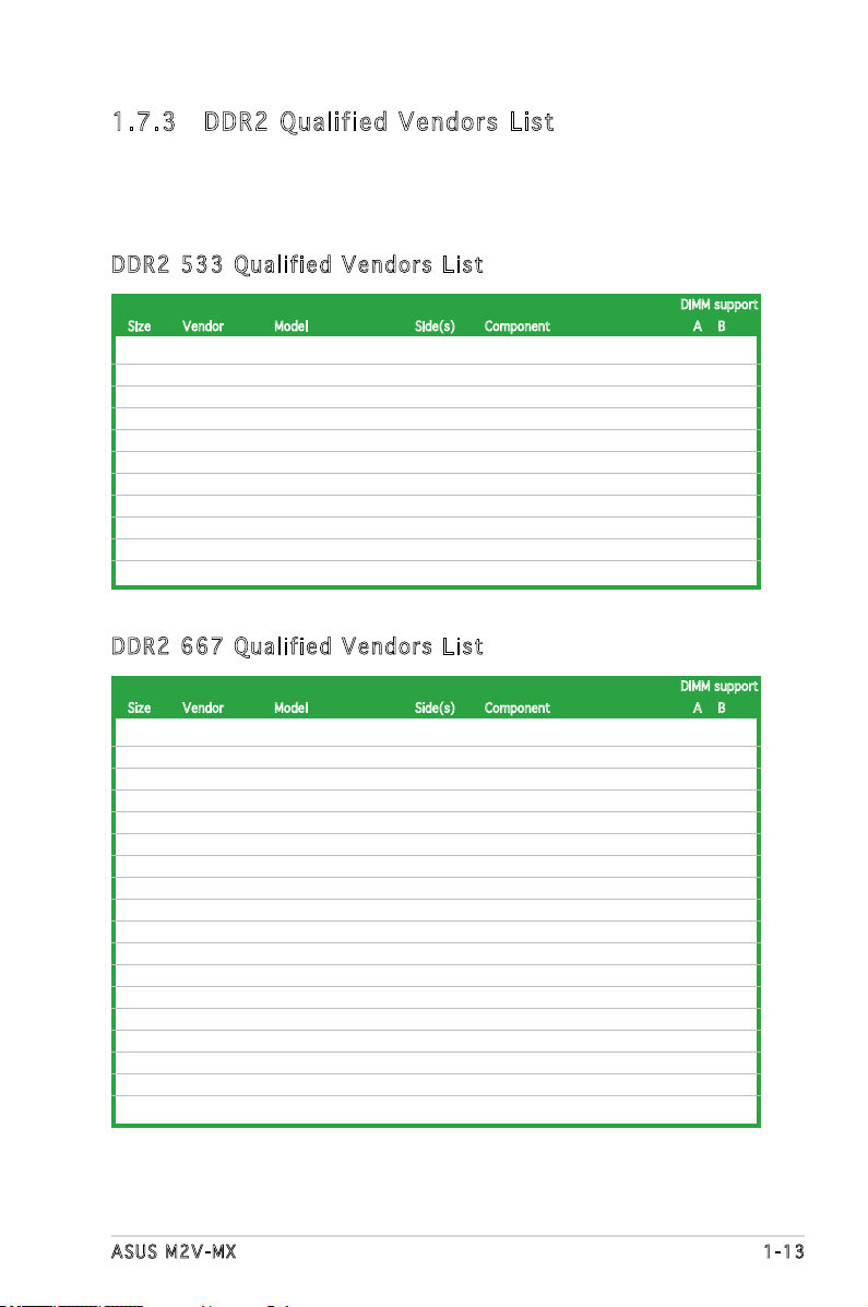
1.7 .3 DDR 2 Qu ali fi ed Ve nd or s L is t
The following table lists the memory modules that have been tested and
qualied for use with this motherboard. Visit the ASUS website (www.asus.
com) for the latest DDR2 DIMM modules for this motherboard.
256MB KINGSTON E5116AF-5C-E SS KVR533D2N4/256 • •
512MB KINGSTON HYB18T512800AF37 SS KVR533D2N4/512 • •
1024MB KINGSTON 5YDIID9GCT DS KVR533D2N4/1G • •
256MB Qimonda HYB18T512160AF-3.7 SS HYS64T32000HU-3.7-A •
256MB Qimonda HYB18T5121608BF-3.7 SS HYS64T32000HU-3.7-B • •
1024MB Qimonda HYB18T512800BF37 DS HYS64T128020HU-3.7-B • •
512MB Hynix HY5PS12821F-C4(ECC) SS HYMP564U728-C4 • •
512MB Hynix HY5PS12821FP-C4(ECC) SS HYMP564U728-C4 • •
1024MB Hynix HY5PS12821AFP-C3 DS HYMP512U64AP8-C3 • •
512MB ELPIDA E5108AB-5C-E(ECC) SS EBE51ED8ABFA-5C-E • •
512MB KINGMAX KKEA88E4AAK-37 SS KLBC28F-A8KE4 • •
DIMM support
Size Vendor Model Side(s) Component A B
DDR 2 53 3 Q u ali f ie d Ve n do r s L i st
512MB KINGSTON E5108AE-6E-E SS KVR667D2N5/512 • •
512MB KINGSTON E5108AE-6E-E SS KVR667D2E5/512 • •
256MB KINGSTON HYB18T256800AF3 SS KVR667D2N5/256 • •
512MB KINGSTON D6408TEBGGL3U SS KVR667D2N5/512 • •
256MB KINGSTON HYB18T256800AF3S SS KVR667D2N5/256 • •
256MB Qimonda HYB18T512160AF-3S SS HYS64T32000HU-3S-A • •
256MB Qimonda HYB18T256800AF3S(ECC) SS HYS72T32000HU-3S-A • •
512MB Qimonda HYB18T512800AF3S(ECC) SS HYS72T64000HU-3S-A • •
1024MB Qimonda HYB18T512800AF3S(ECC) DS HYS72T128020HU-3S-A •
512MB Qimonda HYB18T512800BF3S(ECC) SS HYS72T64000HU-3S-B • •
1024MB Qimonda HYB18T512800BF3S(ECC) DS HYS72T128020HU-3S-B • •
256MB Qimonda HYB18T512160BF-3S SS HYS64T32000HU-3S-B • •
512MB Qimonda HYB18T512800BF3S SS HYS64T64000HU-3S-B • •
1024MB Qimonda HYB18T512800BF3S DS HYS64T128020HU-3S-B • •
256MB SAMSUNG K4T51163QC-ZCE6 SS M378T3354CZ0-CE6 • •
1024MB SAMSUNG ZCE6K4T51083QC DS M378T2953CZ0-CE6 • •
512MB Hynix HY5PS12821AFP-Y5 SS HYMP564U64AP8-Y5 • •
1024MB Hynix HY5PS1G831FP-Y5(ECC) SS HYMP112U72P8-Y5 • •
DIMM support
Size Vendor Model Side(s) Component A B
DDR 2 66 7 Q u ali f ie d Ve n do r s L i st
(continued on the next page)
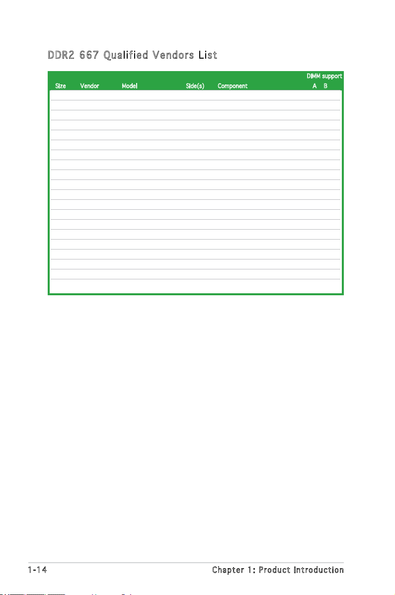
1-14 Chapter 1: Product introduction
DDR 2 66 7 Q u ali f ie d Ve n do r s L i st
DIMM support
Size Vendor Model Side(s) Component A B
512MB Hynix HY5PS12821AFP-Y5(ECC) SS HYMP564U72AP8-Y5 • •
512MB Hynix HY5PS12821AFP-Y4 SS HYMP564U64AP8-Y4 • •
512MB Hynix HY5PS12821AFP-Y4(ECC) SS HYMP564U72AP8-Y4 • •
512MB CORSAIR 64M8CFEG SS VS512MB667D2 • •
1024MB CORSAIR 64M8CFEG SS VS1GB667D2 •
256MB ELPIDA E2508AB-6E-E SS EBE25UC8ABFA-6E-E • •
512MB ELPIDA E5108AE-6E-E SS EBE51UD8AEFA-6E-E • •
512MB A-DATA AD29608A8B-3EG SS M20AD5Q3H3163J1C52 • •
512MB A-DATA AD29608A8A-3EG SS M2OAD5G3H3166I1C52 • •
512MB crucial Heat-Sink Package SS BL6464AA663.8FD • •
1024MB crucial Heat-Sink Package DS BL12864AA663.16FD • •
512MB Apacer AM4B5708GQJS7E SS AU512E667C5KBGC • •
1024MB Apacer AM4B5708GQJS7E DS AU01GE667C5KBGC • •
512MB Apacer AM4B5708PJS7E SS AU512E667C5KBGC • •
512MB Apacer AM4B5708GQJS7E SS AU512E667C5KBGC • •
512MB Kingmax KKEA88B4LAUG-29DX SS KLCC28F-A8KB5 • •
1024MB Kingmax KKEA88B4LAUG-29DX DS KLCD48F-A8KB5 • •
512MB Transcend E5108AE-6E-E SS TS64MLQ64V6J • •
1024MB Transcend E5108AE-6E-E DS TS128MLQ64V6J •
512MB Transcend J12Q3AB-6 SS JM367Q643A-6 • •
(continued on the next page)
ASUS M2V-MX 1-15
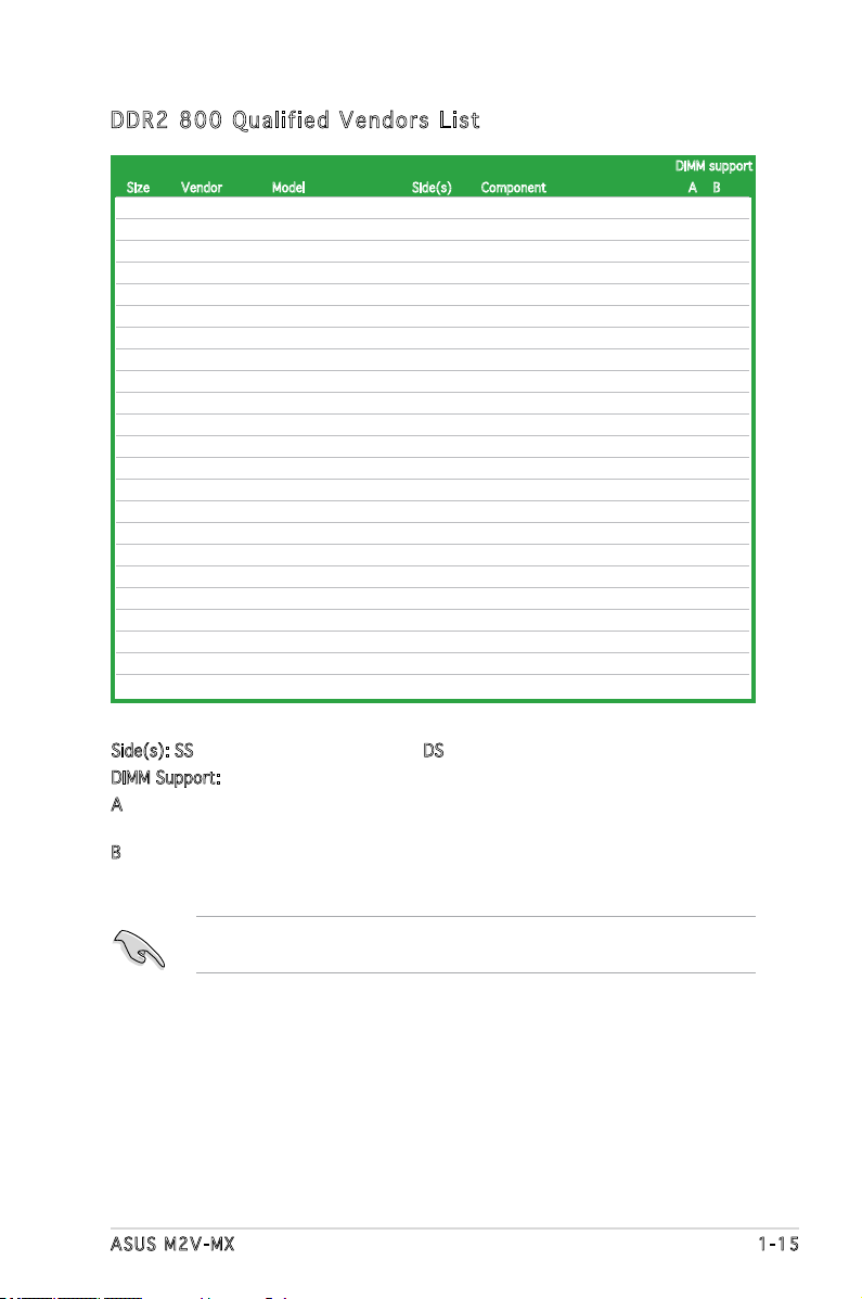
DDR 2 80 0 Q u ali f ie d Ve n do r s L i st
DIMM support
Size Vendor Model Side(s) Component A B
1024MB KINGSTON K4T51083QC DS KVR800D2N5/1G •
1024MB KINGSTON Heat-Sink Package SS KHX6400D2LLK2/1GN • •
512MB Qimonda HYB18T256800AF25 DS HYS64T64520HU-2.5-A • •
512MB Qimonda HYB18T256800AF25F DS HYS64T64020HU-25F-A • •
256MB Qimonda HYB18T512160BF-25F SS HYS64T32000HU-25F-B • •
512MB Qimonda HYB18T512800BF25F SS HYS64T64000HU-25F-B • •
1024MB Qimonda HYB18T512800BF25F DS HYS64T128020HU-25F-B • •
512MB SAMSUNG EDD339XX SS M378T6553CZ3-CE7 • •
256MB SAMSUNG K4T51163QC-ZCE7 SS M378T3354CZ3-CE7 • •
512MB Hynix HY5PS12821BFP-S5 SS HYMP564U64BP8-S5 • •
1024MB Hynix HY5PS12821BFP-S5 DS HYMP512U64BP8-S5 • •
512MB MICRON 5JAIIZ9DQQ SS MT8HTF6464AY-80EA3 • •
1024MB MICRON 5JAIIZ9DQQ DS MT16HTF12864AY-80EA3 • •
512MB MICRON 5ZD22D9GKX SS MT8HTF6464AY-80ED4 • •
1024MB MICRON 5ZD22D9GKX DS MT16HTF12864AY-80ED4 • •
512MB MICRON 6CD22D9GKX SS MT8HTF6464AY-80ED4 • •
1024MB MICRON 6CD22D9GKX DS MT16HTF12864AY-80ED4 • •
1024MB CORSAIR Heat-Sink Package DS CM2X1024-6400C4 • •
512MB A-DATA N/A SS M2OAD6G3H3160J1E52 •
512MB Crucial Heat-Sink Package SS BL6464AA804.8FD • •
1024MB Crucial Heat-Sink Package DS BL12864AA804.16FD • •
512MB Apacer Heat-Sink Package SS AHU512E800C5K1C • •
1024MB Apacer Heat-Sink Package DS AHU01GE800C5K1C • •
Side(s): SS - Single Sided DS - Double Sided
DIMM Support:
A - supports one module inserted in any slot as Single-channel memory
conguration
B - supports one pair of modules inserted into either slots as one pair of Dual-
channel memory conguration
Visit the ASUS website (www.asus.com) for the latest memory Qualied
Vendor List (QVL).
1-16 Chapter 1: Product introduction
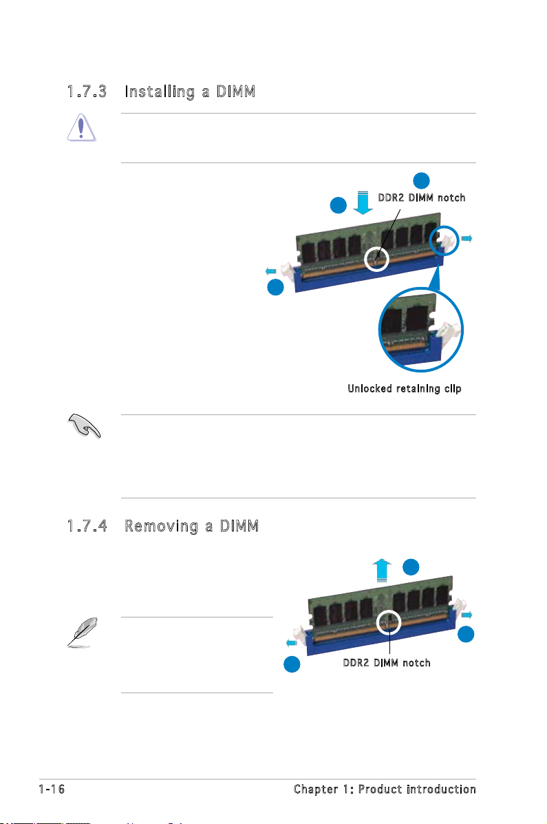
1.7 .3 Ins ta ll ing a D IMM
Unplug the power supply before adding or removing DIMMs or other
system components. Failure to do so can cause severe damage to both
the motherboard and the components.
To install a DIMM:
1. Unlock a DIMM socket by
pressing the retaining clips
outward.
2. Align a DIMM on the socket
such that the notch on the
DIMM matches the break on
the socket.
3. Firmly insert the DIMM into
the socket until the retaining
clips snap back in place and
the DIMM is properly seated.
1.7 .4 Rem ov in g a D IM M
To remove a DIMM:
1. Simultaneously press the
retaining clips outward to unlock
the DIMM.
2. Remove the DIMM from the socket.
• A DDR2 DIMM is keyed with a notch so that it ts in only one
direction. Do not force a DIMM into a socket to avoid damaging the
DIMM.
• The DDR2 DIMM sockets do not support DDR DIMMs. DO not install
DDR DIMMs to the DDR2 DIMM sockets.
Support the DIMM lightly with
your ngers when pressing
the retaining clips. The DIMM
might get damaged when it
ips out with extra force.
1
2
1
DDR 2 D IMM n o t c h
Unl o c k ed re t a i ning c l i p
DDR 2 D IMM n o t c h
1
2
3
ASUS M2V-MX 1-17
1.8 Expansion slots
In the future, you may need to install expansion cards. The following
sub-sections describe the slots and the expansion cards that they support.
1.8 .1 Ins ta ll ing a n ex p an si on ca rd
To install an expansion card:
1. Before installing the expansion card, read the documentation that
came with it and make the necessary hardware settings for the card.
2. Remove the system unit cover (if your motherboard is already
installed in a chassis).
3. Remove the bracket opposite the slot that you intend to use. Keep
the screw for later use.
4. Align the card connector with the slot and press rmly until the card is
completely seated on the slot.
5. Secure the card to the chassis with the screw you removed earlier.
6. Replace the system cover.
1.8 .2 Con fi gu rin g an e x pa ns io n c ar d
After installing the expansion card, congure it by adjusting the software
settings.
1. Turn on the system and change the necessary BIOS settings, if any.
See Chapter 2 for information on BIOS setup.
2. Assign an IRQ to the card. Refer to the tables on the next page.
3. Install the software drivers for the expansion card.
Make sure to unplug the power cord before adding or removing
expansion cards. Failure to do so may cause you physical injury and
damage motherboard components.
 Loading...