

ASUS M2NPV-MX User Manual

M2NPV-MX
Motherboard

E2629E2629
E2629
E2629E2629
First Edition V1First Edition V1
First Edition V1
First Edition V1First Edition V1
May 2006May 2006
May 2006
May 2006May 2006
Copyright © 2006 ASUSTeK COMPUTER INC. All Rights Reserved.Copyright © 2006 ASUSTeK COMPUTER INC. All Rights Reserved.
Copyright © 2006 ASUSTeK COMPUTER INC. All Rights Reserved.
Copyright © 2006 ASUSTeK COMPUTER INC. All Rights Reserved.Copyright © 2006 ASUSTeK COMPUTER INC. All Rights Reserved.
No part of this manual, including the products and software described in it, may be reproduced,
transmitted, transcribed, stored in a retrieval system, or translated into any language in any form
or by any means, except documentation kept by the purchaser for backup purposes, without the
express written permission of ASUSTeK COMPUTER INC. (“ASUS”).
Product warranty or service will not be extended if: (1) the product is repaired, modified or
altered, unless such repair, modification of alteration is authorized in writing by ASUS; or (2) the
serial number of the product is defaced or missing.
ASUS PROVIDES THIS MANUAL “AS IS” WITHOUT WARRANTY OF ANY KIND, EITHER EXPRESS OR
IMPLIED, INCLUDING BUT NOT LIMITED TO THE IMPLIED WARRANTIES OR CONDITIONS OF
MERCHANTABILITY OR FITNESS FOR A PARTICULAR PURPOSE. IN NO EVENT SHALL ASUS, ITS
DIRECTORS, OFFICERS, EMPLOYEES OR AGENTS BE LIABLE FOR ANY INDIRECT, SPECIAL,
INCIDENTAL, OR CONSEQUENTIAL DAMAGES (INCLUDING DAMAGES FOR LOSS OF PROFITS, LOSS
OF BUSINESS, LOSS OF USE OR DATA, INTERRUPTION OF BUSINESS AND THE LIKE), EVEN IF ASUS
HAS BEEN ADVISED OF THE POSSIBILITY OF SUCH DAMAGES ARISING FROM ANY DEFECT OR
ERROR IN THIS MANUAL OR PRODUCT.
SPECIFICATIONS AND INFORMATION CONTAINED IN THIS MANUAL ARE FURNISHED FOR
INFORMATIONAL USE ONLY, AND ARE SUBJECT TO CHANGE AT ANY TIME WITHOUT NOTICE, AND
SHOULD NOT BE CONSTRUED AS A COMMITMENT BY ASUS. ASUS ASSUMES NO RESPONSIBILITY
OR LIABILITY FOR ANY ERRORS OR INACCURACIES THAT MAY APPEAR IN THIS MANUAL,
INCLUDING THE PRODUCTS AND SOFTWARE DESCRIBED IN IT.
Products and corporate names appearing in this manual may or may not be registered
trademarks or copyrights of their respective companies, and are used only for identification or
explanation and to the owners’ benefit, without intent to infringe.
iiii
ii
iiii

Contents
Notices ................................................................................................ vi
Safety information ............................................................................. vii
M2NPV-MX specifications summary .................................................. viii
Chapter 1: Product introductionChapter 1: Product introduction
Chapter 1: Product introduction
Chapter 1: Product introductionChapter 1: Product introduction
1.1 Welcome! .............................................................................. 1-2
1.2 Package contents ................................................................. 1-2
1.3 Special features .................................................................... 1-2
1.3.1 Product highlights ................................................... 1-2
1.3.2 Innovative ASUS features ....................................... 1-5
1.4 Before you proceed .............................................................. 1-6
1.5 Motherboard overview .......................................................... 1-7
1.5.1 Motherboard layout ................................................ 1-7
1.5.2 Placement direction ................................................ 1-8
1.5.3 Screw holes ............................................................ 1-8
1.6 Central Processing Unit (CPU) .............................................. 1-9
1.6.1 Installing the CPU ................................................... 1-9
1.6.2 Installing the heatsink and fan ............................. 1-11
1.7 System memory ................................................................. 1-13
1.7.1 Overview ............................................................... 1-13
1.7.2 Memory configurations ......................................... 1-13
1.7.3 Installing a DIMM ...................................................1-17
1.7.4 Removing a DIMM ................................................. 1-17
1.8 Expansion slots ................................................................... 1-18
1.8.1 Installing an expansion card .................................. 1-18
1.8.2 Configuring an expansion card .............................. 1-18
1.8.3 PCI slots ................................................................ 1-20
1.8.4 PCI Express x1 slot ............................................... 1-20
1.8.5 PCI Express x16 slot ............................................. 1-20
1.9 Jumpers .............................................................................. 1-21
1.10 Connectors .........................................................................1-24
1.10.1 Rear panel connectors .......................................... 1-24
1.10.2 Internal connectors ............................................... 1-26
iiiiii
iii
iiiiii

Contents
Chapter 2: BIOS setupChapter 2: BIOS setup
Chapter 2: BIOS setup
Chapter 2: BIOS setupChapter 2: BIOS setup
2.1 Managing and updating your BIOS ........................................ 2-2
2.1.1 ASUS Update utility ................................................ 2-2
2.1.2 Creating a bootable floppy disk .............................. 2-5
2.1.3 ASUS EZ Flash 2 utility ........................................... 2-6
2.1.4 Updating the BIOS .................................................. 2-7
2.1.5 Saving the current BIOS file .................................... 2-9
2.1.6 ASUS CrashFree BIOS 2 utility .............................. 2-10
2.2 BIOS setup program ........................................................... 2-11
2.2.1 BIOS menu screen ................................................ 2-12
2.2.2 Menu bar ............................................................... 2-12
2.2.3 Legend bar ........................................................... 2-13
2.2.4 Menu items ...........................................................2-13
2.2.5 Sub-menu items ................................................... 2-13
2.2.6 Configuration fields .............................................. 2-13
2.2.7 Pop-up window ..................................................... 2-14
2.2.8 General help .......................................................... 2-14
2.3 Main menu .......................................................................... 2-15
2.3.1 System Time ......................................................... 2-15
2.3.2 System Date ......................................................... 2-15
2.3.3 Legacy Diskette A ................................................2-15
2.3.4 Primary and Secondary IDE Master/Slave ............. 2-16
2.3.5 First, Second, Third, Fourth SATA Master ............2-18
2.3.6 HDD SMART Monitoring ........................................ 2-19
2.3.7 Installed Memory .................................................. 2-19
2.3.8 Usable Memory ..................................................... 2-19
2.4 Advanced menu .................................................................. 2-20
2.4.1 JumperFree Configuration ..................................... 2-20
2.4.2 AI NET2 ................................................................ 2-22
2.4.3 CPU Configuration ................................................. 2-22
2.4.4 Chipset ................................................................. 2-24
2.4.5 PCIPnP ................................................................... 2-25
2.4.6 Onboard Devices Configuration ............................ 2-26
iviv
iv
iviv

Contents
2.5 Power menu ........................................................................ 2-30
2.5.1 ACPI Suspend Type...............................................2-30
2.5.2 ACPI APIC Support ................................................ 2-30
2.5.3 APM Configuration ................................................ 2-30
2.5.4 Hardware Monitor ................................................. 2-33
2.6 Boot menu .......................................................................... 2-34
2.6.1 Boot Device Priority .............................................. 2-34
2.6.2 Removable Drives ................................................. 2-34
2.6.3 Hard Disk Drives ................................................... 2-35
2.6.4 CDROM Drives ....................................................... 2-35
2.6.5 Boot Settings Configuration ................................. 2-35
2.6.6 Security ................................................................ 2-38
2.7 Tools menu ......................................................................... 2-40
2.7.1 ASUS EZ Flash 2 ................................................... 2-40
2.8 Exit menu ........................................................................... 2-41
Chapter 3: Software supportChapter 3: Software support
Chapter 3: Software support
Chapter 3: Software supportChapter 3: Software support
3.1 Installing an operating system ............................................. 3-2
3.2 Support CD information ........................................................ 3-2
3.2.1 Running the support CD ......................................... 3-2
3.2.2 Drivers menu .......................................................... 3-3
3.2.3 Utilities menu .......................................................... 3-4
3.2.4 Make Disk menu ...................................................... 3-5
3.2.5 Manual menu ........................................................... 3-6
3.2.6 ASUS Contact information ...................................... 3-7
3.2.7 Other information ................................................... 3-7
3.2 Creating a RAID driver disk ................................................... 3-9
vv
v
vv

Notices
Federal Communications Commission StatementFederal Communications Commission Statement
Federal Communications Commission Statement
Federal Communications Commission StatementFederal Communications Commission Statement
This device complies with Part 15 of the FCC Rules. Operation is subject to
the following two conditions:
•
This device may not cause harmful interference, and
•
This device must accept any interference received including interference
that may cause undesired operation.
This equipment has been tested and found to comply with the limits for a
Class B digital device, pursuant to Part 15 of the FCC Rules. These limits are
designed to provide reasonable protection against harmful interference in a
residential installation. This equipment generates, uses and can radiate radio
frequency energy and, if not installed and used in accordance with
manufacturer’s instructions, may cause harmful interference to radio
communications. However, there is no guarantee that interference will not
occur in a particular installation. If this equipment does cause harmful
interference to radio or television reception, which can be determined by
turning the equipment off and on, the user is encouraged to try to correct
the interference by one or more of the following measures:
•
Reorient or relocate the receiving antenna.
•
Increase the separation between the equipment and receiver.
•
Connect the equipment to an outlet on a circuit different from that to
which the receiver is connected.
•
Consult the dealer or an experienced radio/TV technician for help.
The use of shielded cables for connection of the monitor to the graphics
card is required to assure compliance with FCC regulations. Changes or
modifications to this unit not expressly approved by the party
responsible for compliance could void the user’s authority to operate
this equipment.
Canadian Department of Communications StatementCanadian Department of Communications Statement
Canadian Department of Communications Statement
Canadian Department of Communications StatementCanadian Department of Communications Statement
This digital apparatus does not exceed the Class B limits for radio noise
emissions from digital apparatus set out in the Radio Interference
Regulations of the Canadian Department of Communications.
This class B digital apparatus complies with CanadianThis class B digital apparatus complies with Canadian
This class B digital apparatus complies with Canadian
This class B digital apparatus complies with CanadianThis class B digital apparatus complies with Canadian
ICES-003.ICES-003.
ICES-003.
ICES-003.ICES-003.
vivi
vi
vivi

Safety information
Electrical safetyElectrical safety
Electrical safety
Electrical safetyElectrical safety
•
To prevent electrical shock hazard, disconnect the power cable from the
electrical outlet before relocating the system.
•
When adding or removing devices to or from the system, ensure that the
power cables for the devices are unplugged before the signal cables are
connected. If possible, disconnect all power cables from the existing
system before you add a device.
•
Before connecting or removing signal cables from the motherboard,
ensure that all power cables are unplugged.
•
Seek professional assistance before using an adapter or extension cord.
These devices could interrupt the grounding circuit.
•
Make sure that your power supply is set to the correct voltage in your
area. If you are not sure about the voltage of the electrical outlet you are
using, contact your local power company.
•
If the power supply is broken, do not try to fix it by yourself. Contact a
qualified service technician or your retailer.
Operation safetyOperation safety
Operation safety
Operation safetyOperation safety
•
Before installing the motherboard and adding devices on it, carefully read
all the manuals that came with the package.
•
Before using the product, make sure all cables are correctly connected
and the power cables are not damaged. If you detect any damage,
contact your dealer immediately.
•
To avoid short circuits, keep paper clips, screws, and staples away from
connectors, slots, sockets and circuitry.
•
Avoid dust, humidity, and temperature extremes. Do not place the
product in any area where it may become wet.
•
Place the product on a stable surface.
•
If you encounter technical problems with the product, contact a qualified
service technician or your retailer.
The symbol of the crossed out wheeled bin indicates that the product
(electrical and electronic equipment) should not be placed in municipal
waste. Please check local regulations for disposal of electronic products.
viivii
vii
viivii

M2NPV-MX specifications summary
CPUCPU
CPU
CPUCPU
Support AMD socket AM2 for AMD Athlon™ 64FX/
Athlon™ 64 X2/Athlon™ 64/Sempron processors
AMD64 architecture enables simultaneous 32-bit and
64-bit computing
Supports AMD Cool ‘n’ Quiet™ Technology
AMD Live!™ Ready
ChipsetChipset
Chipset
ChipsetChipset
Front Side BusFront Side Bus
Front Side Bus
Front Side BusFront Side Bus
MemoryMemory
Memory
MemoryMemory
Expansion slotsExpansion slots
Expansion slots
Expansion slotsExpansion slots
GraphicsGraphics
Graphics
GraphicsGraphics
StorageStorage
Storage
StorageStorage
Northbridge: NVIDIA® GeForce™ 6150 GPU
Southbridge: NVIDIA® nForce™430 MCP
2000/1600 MT/s
Dual-channel memory architecture
4 x 240-pin DIMM sockets support up to 8 GB of
unbufferred ECC/non-ECC 800/667/533 MHz
DDR2 memory modules
1 x PCI Express™ x16 slot
1 x PCI Express™ x1 slot
2 x PCI slots
Integrated in the NVIDIA® GeForce™ 6 Graphics
Processing Unit (GPU)
Dual VGA output: DVI-D and RGB
High definition video processing with maximum
resolution of 1920 x 1440 pixels (@75Hz) for RGB
display
Note:Note:
Note:
DVI-D only supports digital display. You
Note:Note:
cannot convert DVI-D to output RGB signal to
CRT display.
TV-out: SDTV& HDTV (with optional TV-Out module)
Note:Note:
Note:
RGB and TV-Out cannot be used simultaneously.
Note:Note:
NVIDIA® nForce™430 media and communications
processor (MCP) supports:
- 2 x Ultra DMA 133/100/66/33 interfaces for four
(4) hard disk drives
- 4 x Serial ATA 3 Gb/s hard disk drives supporting
RAID 0, RAID 1, RAID 0+1, RAID 5, and JBOD
configuration
High DefinitionHigh Definition
High Definition
High DefinitionHigh Definition
AudioAudio
Audio
AudioAudio
LANLAN
LAN
LANLAN
USBUSB
USB
USBUSB
viiiviii
viii
viiiviii
SoundMAX® ADI AD1986A 5.1-channel CODEC
Supports Jack Sensing technology
S/PDIF out interface
NVIDIA® nForce™430 built-in Gigabit MAC with external
Marvell® PHY
Supports up to 8 USB 2.0 ports
(continued on the next page)

M2NPV-MX specifications summary
ManageabilityManageability
Manageability
ManageabilityManageability
Special featuresSpecial features
Special features
Special featuresSpecial features
BIOS featuresBIOS features
BIOS features
BIOS featuresBIOS features
Rear panelRear panel
Rear panel
Rear panelRear panel
InternalInternal
Internal
InternalInternal
connectorsconnectors
connectors
connectorsconnectors
WfM2.0, DMI2.0, WOL by PME, WOR, PXE, Chassis
Intrusion
ASUS Q-Fan
ASUS C.P.R. (CPU Parameter Recall)
ASUS CrashFree BIOS 2
ASUS EZ Flash 2
ASUS MyLogo™
Stepless Frequency Selection (SFS) allows FSB tuning
from 200 MHz to 400 MHz at 1 MHz increment
Note:Note:
Note:
ASUS CrashFree BIOS 2 and ASUS EZ Flash 2 only
Note:Note:
support VGA/RGB output.
4 Mb Flash ROM, Award BIOS, PnP, DMI2.0, WfM2.0, ACPI
2.0, SM BIOS 2.3
1 x Parallel port
1 x LAN (RJ-45) port
4 x USB 2.0 ports
1 x VGA/RGB Out port
1 x VGA/DVI-D port
1 x PS/2 keyboard port
1 x PS/2 mouse port
5.1-channel audio ports
1 x Front panel audio connector
1 x CD audio in connector
1 x Chassis intrusion connector
1 x CPU fan connector
1 x Chassis fan connectors
1 x Floppy disk drive connector
1 x COM connectors
1 x Primary IDE connector
1 x Secondary IDE connector
1 x S/PDIF Out connector
1 x TV Out connector
4 x Serial ATA connectors
2 x USB 2.0 connectors for 4 additional USB 2.0 ports
1 x 24-pin ATX power connector
1 x 4-pin x ATX 12V power connector
1 x System panel connector
(continued on the next page)
ixix
ix
ixix

M2NPV-MX specifications summary
PowerPower
Power
PowerPower
RequirementRequirement
Requirement
RequirementRequirement
Form FactorForm Factor
Form Factor
Form FactorForm Factor
Support CDSupport CD
Support CD
Support CDSupport CD
contentscontents
contents
contentscontents
*Specifications are subject to change without notice.
ATX power supply (with 24-pin and 4-pin 12 V plugs)
ATX 12 V 2.0 compliant
uATX: 9.6 in. x 9.6 in. (24.5cm x 24.5cm)
Device drivers
ASUS PC Probe II
AMD Cool ‘n’Quiet™ utility
ASUS Live Update utility
Anti-virus software (OEM version)
xx
x
xx

This chapter describes the motherboard
features and the new technologies
it supports.
introduction
Product
1

1.1 Welcome!
®®
®
Thank you for buying an ASUSThank you for buying an ASUS
Thank you for buying an ASUS
Thank you for buying an ASUSThank you for buying an ASUS
The motherboard delivers a host of new features and latest technologies,
making it another standout in the long line of ASUS quality motherboards!
Before you start installing the motherboard, and hardware devices on it,
check the items in your package with the list below.
®®
M2NPV-MX motherboard! M2NPV-MX motherboard!
M2NPV-MX motherboard!
M2NPV-MX motherboard! M2NPV-MX motherboard!
1.2 Package contents
Check your motherboard package for the following items.
MotherboardMotherboard
Motherboard ASUS M2NPV-MX motherboard
MotherboardMotherboard
CablesCables
Cables 1 x Serial ATA signal cables
CablesCables
1 x Serial ATA power cable
1 x Ultra DMA 133/100/66 cable
1 x Floppy disk drive cable
AccessoriesAccessories
Accessories I/O shield
AccessoriesAccessories
Application CDApplication CD
Application CD ASUS motherboard support CD
Application CDApplication CD
DocumentationDocumentation
Documentation User guide
DocumentationDocumentation
If any of the above items is damaged or missing, contact your retailer.
1.3 Special features
1.3.11.3.1
1.3.1
1.3.11.3.1
Latest processor technology Latest processor technology
Latest processor technology
Latest processor technology Latest processor technology
The motherboard supports AMD socket AM2 single-core Athlon 64/
Sempron and dual-core Athlon 64 X2/Athlon 64 FX processors with 2MB/
1MB/512KB L2 cache, which is based on 64-bit architecture. It features
2000/1600 MT/s HyperTransport Bus, dual-channel un-buffered DDR2 800
memory support and AMD Cool ‘n’ Quiet Technology. See page 1-9 for
details.
1-21-2
1-2
1-21-2
Product highlightsProduct highlights
Product highlights
Product highlightsProduct highlights
Chapter 1: Product introductionChapter 1: Product introduction
Chapter 1: Product introduction
Chapter 1: Product introductionChapter 1: Product introduction
AMD Cool ‘n’ Quiet Technology AMD Cool ‘n’ Quiet Technology
AMD Cool ‘n’ Quiet Technology
AMD Cool ‘n’ Quiet Technology AMD Cool ‘n’ Quiet Technology
The motherboard supports the AMD Cool ‘n’ Quiet Technology, which
monitors system operation and automatically adjusts CPU voltage and
frequency for a cool and quiet operating environment. See page 2-23 for
details.
®®
®
NVIDIANVIDIA
NVIDIA
NVIDIANVIDIA
and NVIDIAand NVIDIA
and NVIDIA
and NVIDIAand NVIDIA
®®
GeForce™ 6150 GPU GeForce™ 6150 GPU
GeForce™ 6150 GPU
GeForce™ 6150 GPU GeForce™ 6150 GPU
®®
®
®®
nForce™ 430 MCP chipsets nForce™ 430 MCP chipsets
nForce™ 430 MCP chipsets
nForce™ 430 MCP chipsets nForce™ 430 MCP chipsets
The NVIDIA® GeForce™ 6150 graphics processing unit (GPU) Northbridge
supports Microsoft® DirectX 9.0 Shader Model 3.0, dual VGA out (RGB and
DVI-D), NVIDIA® PureVideo Technology with unprecedented integrated
video quality, TV-out, and PCI Express interface.
®
The NVIDIA
nForce™ 430 media and communications processor (MCP)
Southbridge delivers NVIDIA® Gigabit and NVIDIA® MediaShield storage
management technology allowing easy RAID configuration (RAID 0, RAID 1,
RAID 0+1, RAID 5, and JBOD) for Serial ATA 3Gb/s.
DDR2 memory support DDR2 memory support
DDR2 memory support
DDR2 memory support DDR2 memory support
The motherboard supports DDR2 memory which features data transfer
rates of 800MHz/667 MHz/533 MHz to meet the higher bandwidth
requirements of the latest 3D graphics, multimedia, and Internet
applications. The dual-channel DDR2 architecture doubles the bandwidth of
your system memory to boost system performance, eliminating
bottlenecks with peak bandwidths of up to 12.8 GB/s. See pages 1-13 to
1-16 for details.
PCI Express™ interface PCI Express™ interface
PCI Express™ interface
PCI Express™ interface PCI Express™ interface
The motherboard fully supports PCI Express, the latest I/O interconnect
technology that speeds up the PCI bus. PCI Express features point-to-point
serial interconnections between devices and allows higher clockspeeds by
carrying data in packets. This high speed interface is software compatible with
existing PCI specifications. See page 1-20 for details.
ASUS M2NPV-MXASUS M2NPV-MX
ASUS M2NPV-MX
ASUS M2NPV-MXASUS M2NPV-MX
1-31-3
1-3
1-31-3

Serial ATA 3Gb/s technology Serial ATA 3Gb/s technology
Serial ATA 3Gb/s technology
Serial ATA 3Gb/s technology Serial ATA 3Gb/s technology
The motherboard supports next-generation SATA hard drives based on the
new SATA 3Gb/s storage specification. The onboard NVIDIA
MCP southbridge allows RAID 0, RAID 1, RAID 0+1, RAID 5, and JBOD
configurations for four SATA connectors.
Gigabit LAN solution Gigabit LAN solution
Gigabit LAN solution
Gigabit LAN solution Gigabit LAN solution
NVIDIA® Gb LAN controller delivers transfer speeds up to ten times faster
than conventional 10/100 Ethernet connections. Gigabit LAN is the
networking standard for the early future and is ideal for handling large
amounts of data such as video, audio, and voice.
USB 2.0 technology USB 2.0 technology
USB 2.0 technology
USB 2.0 technology USB 2.0 technology
The motherboard implements the Universal Serial Bus (USB) 2.0
specification, dramatically increasing the connection speed from the
12 Mbps bandwidth on USB 1.1 to a fast 480 Mbps on USB 2.0. USB 2.0 is
backward compatible with USB 1.1. See pages 1-24 and 1-30 for details.
®
nForce 430
High Definition Audio High Definition Audio
High Definition Audio
High Definition Audio High Definition Audio
SoundMAX is the highest performing, most reliable and user-friendly PC
audio solution for business professionals, audiophiles, musicians, and
gamers. Hear crystal-clear quality from all your audio - MP3 playback, home
theatre, advanced gaming, VOIP and more, and never worry - SoundMAX
high-definition audio is there to enhance your experience!
1-41-4
1-4
1-41-4
Chapter 1: Product introductionChapter 1: Product introduction
Chapter 1: Product introduction
Chapter 1: Product introductionChapter 1: Product introduction

1.3.21.3.2
1.3.2
1.3.21.3.2
ASUS CrashFree BIOS 2 ASUS CrashFree BIOS 2
ASUS CrashFree BIOS 2
ASUS CrashFree BIOS 2 ASUS CrashFree BIOS 2
This feature allows you to restore the original BIOS data from the support CD
in case when the BIOS codes and data are corrupted. This protection
eliminates the need to buy a replacement BIOS chip. See page 2-10 for
details.
ASUS EZ Flash 2 ASUS EZ Flash 2
ASUS EZ Flash 2
ASUS EZ Flash 2 ASUS EZ Flash 2
With the ASUS EZ Flash, you can easily update the system BIOS even
before loading the operating system. No need to use a DOS-based utility or
boot from a floppy disk. See page 2-6 for details.
ASUS Q-Fan technology ASUS Q-Fan technology
ASUS Q-Fan technology
ASUS Q-Fan technology ASUS Q-Fan technology
The ASUS Q-Fan technology smartly adjusts the fan speeds according to
the system loading to ensure quiet, cool, and efficient operation.
See page 2-33 for details.
C.P.R. (CPU Parameter Recall) C.P.R. (CPU Parameter Recall)
C.P.R. (CPU Parameter Recall)
C.P.R. (CPU Parameter Recall) C.P.R. (CPU Parameter Recall)
The C.P.R. feature of the motherboard BIOS allows automatic re-setting to
the BIOS default settings in case the system hangs due to overclocking.
When the system hangs due to overclocking, C.P.R. eliminates the need to
open the system chassis and clear the RTC data. Simply shut down and
reboot the system, and the BIOS automatically restores the CPU default
setting for each parameter.
Innovative ASUS featuresInnovative ASUS features
Innovative ASUS features
Innovative ASUS featuresInnovative ASUS features
ASUS MyLogo™ ASUS MyLogo™
ASUS MyLogo™
ASUS MyLogo™ ASUS MyLogo™
This feature allows you to personalize and add style to your system with
customizable boot logos. See page 2-37 for details.
ASUS M2NPV-MXASUS M2NPV-MX
ASUS M2NPV-MX
ASUS M2NPV-MXASUS M2NPV-MX
1-51-5
1-5
1-51-5
1.4 Before you proceed
®
d
Take note of the following precautions before you install motherboard
components or change any motherboard settings.
• Unplug the power cord from the wall socket before touching any
component.
• Use a grounded wrist strap or touch a safely grounded object or a
metal object, such as the power supply case, before handling
components to avoid damaging them due to static electricity
• Hold components by the edges to avoid touching the ICs on them.
• Whenever you uninstall any component, place it on a grounded
antistatic pad or in the bag that came with the component.
Before you install or remove any component, ensureBefore you install or remove any component, ensure
•
Before you install or remove any component, ensure
Before you install or remove any component, ensureBefore you install or remove any component, ensure
that the ATX power supply is switched off or thethat the ATX power supply is switched off or the
that the ATX power supply is switched off or the
that the ATX power supply is switched off or thethat the ATX power supply is switched off or the
power cord is detached from the power supply. power cord is detached from the power supply.
power cord is detached from the power supply. Failure
power cord is detached from the power supply. power cord is detached from the power supply.
to do so may cause severe damage to the motherboard, peripherals,
and/or components.
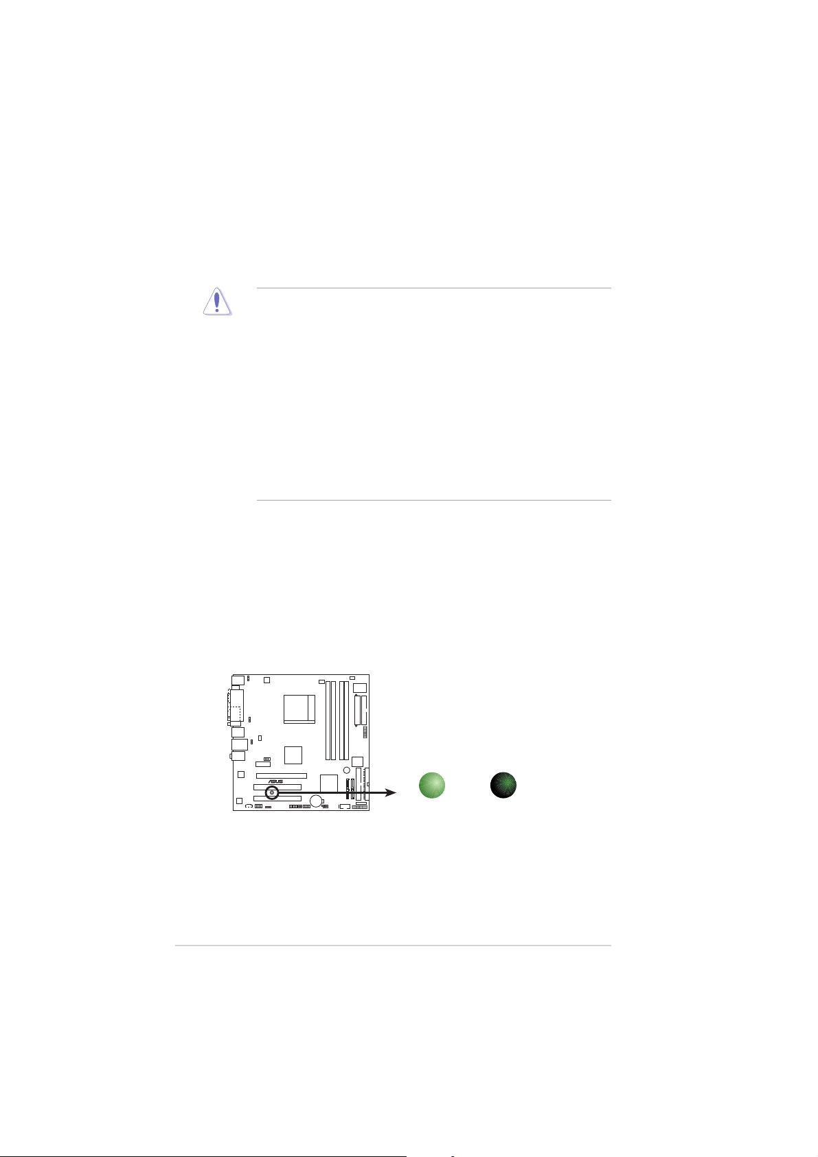
Onboard LEDOnboard LED
Onboard LED
Onboard LEDOnboard LED
The motherboard comes with a standby power LED that lights up to
indicate that the system is ON, in sleep mode, or in soft-off mode.
This is a reminder that you should shut down the system and unplug
the power cable before removing or plugging in any motherboard
component. The illustration below shows the location of the onboard
LED.
M2NPV-MX
M2NPV-MX Onboard LED
1-61-6
1-6
1-61-6
SB_PWR
ON
Standby
Power
Chapter 1: Product introductionChapter 1: Product introduction
Chapter 1: Product introduction
Chapter 1: Product introductionChapter 1: Product introduction
OFF
Powere
Off
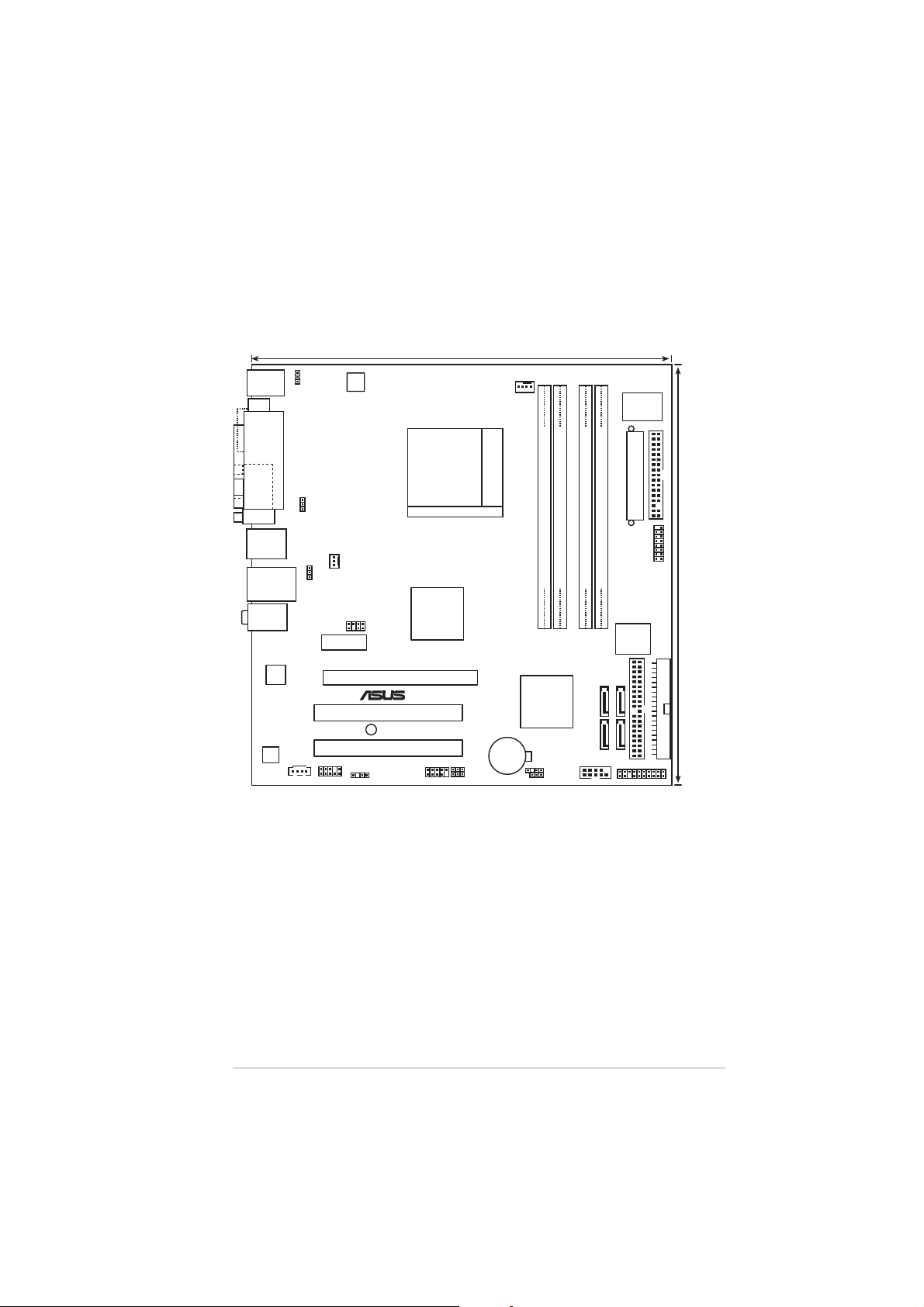
1.5 Motherboard overview
®
24.5cm (9.6in)
1.5.11.5.1
1.5.1
1.5.11.5.1
PS/2KBMS
T: Mouse
B: Keyboard
DVI
VGA
USB12
LAN_USB34
Top:Line In
Center:Line Out
Bottom:Mic In
88E1116
AD
1986A
Motherboard layoutMotherboard layout
Motherboard layout
Motherboard layoutMotherboard layout
KBPWR
ATX12V
PARALLEL PORT
USBPW12
CHA_FAN1
USBPW34
nVIDIA
TV_OUT
GeForce™6150
PCIEX1_1
M2NPV-MX
PCIEX16
PCI1
SB_PWR
PCI2
CD
AAFP
SPDIF_OUT
®
USBPW78
USBPW56
CPU_FAN
CMOS Power
USB78USB56
Socket AM2
nVIDIA
nForce™430
CR2032 3V
Lithium Cell
CHASSIS
CLRTC
Super
I/O
FLOPPY
EATXPWR
GAME
DDR2 DIMM_A1 (64 bit,240-pin module)
DDR2 DIMM_B2 (64 bit,240-pin module)
DDR2 DIMM_B1 (64 bit, 240-pin module)
DDR2 DIMM_A2 (64 bit,240-pin module)
4Mb
BIOS
24.5cm (9.6in)
PRI_IDE
®
SATA4SATA2
SATA3SATA1
COM1
SEC_IDE
PANEL
ASUS M2NPV-MXASUS M2NPV-MX
ASUS M2NPV-MX
ASUS M2NPV-MXASUS M2NPV-MX
1-71-7
1-7
1-71-7
®
1.5.21.5.2
1.5.2
1.5.21.5.2
Placement directionPlacement direction
Placement direction
Placement directionPlacement direction
When installing the motherboard, make sure that you place it into the
chassis in the correct orientation. The edge with external ports goes to the
rear part of the chassis as indicated in the image below.
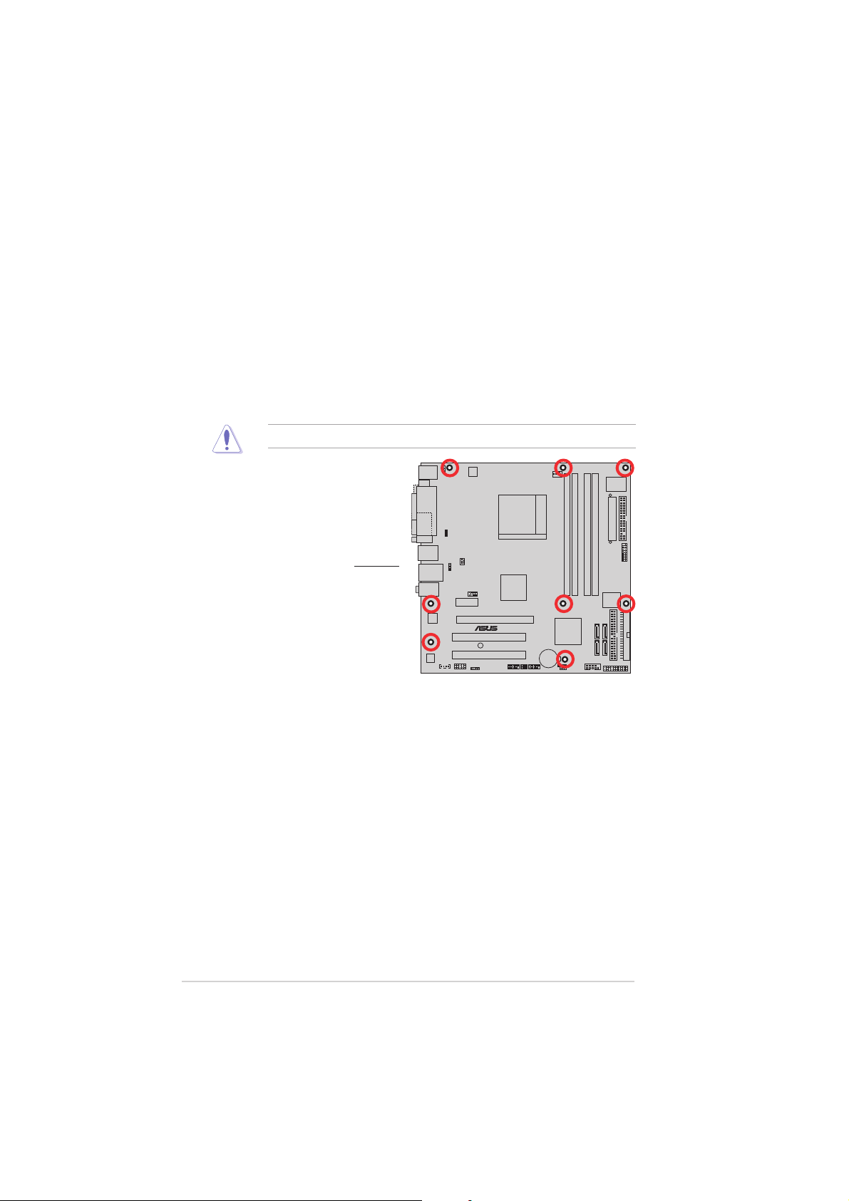
1.5.31.5.3
1.5.3
1.5.31.5.3
Screw holesScrew holes
Screw holes
Screw holesScrew holes
Place eight (8) screws into the holes indicated by circles to secure the
motherboard to the chassis.
Do not overtighten the screws! Doing so can damage the motherboard.
Place this side towardsPlace this side towards
Place this side towards
Place this side towardsPlace this side towards
the rear of the chassisthe rear of the chassis
the rear of the chassis
the rear of the chassisthe rear of the chassis
M2NPV-MX
1-81-8
1-8
1-81-8
Chapter 1: Product introductionChapter 1: Product introduction
Chapter 1: Product introduction
Chapter 1: Product introductionChapter 1: Product introduction
1.6 Central Processing Unit (CPU)
®
The motherboard comes with a 940-pin AM2 socket designed for the AMD
Athlon™ 64 X2/Athlon™ 64/Athlon™ FX/Sempron™ processor.
The AM2 socket has a different pinout from the 940-pin socket
designed for the AMD Opteron™ processor. Make sure you use a CPU is
designed for the AM2 socket. The CPU fits in only one correct
orientation. DO NOT force the CPU into the socket to prevent bending
the connectors on the socket and damaging the CPU!
1.6.11.6.1
1.6.1
1.6.11.6.1
Installing the CPUInstalling the CPU
Installing the CPU
Installing the CPUInstalling the CPU
To install a CPU.
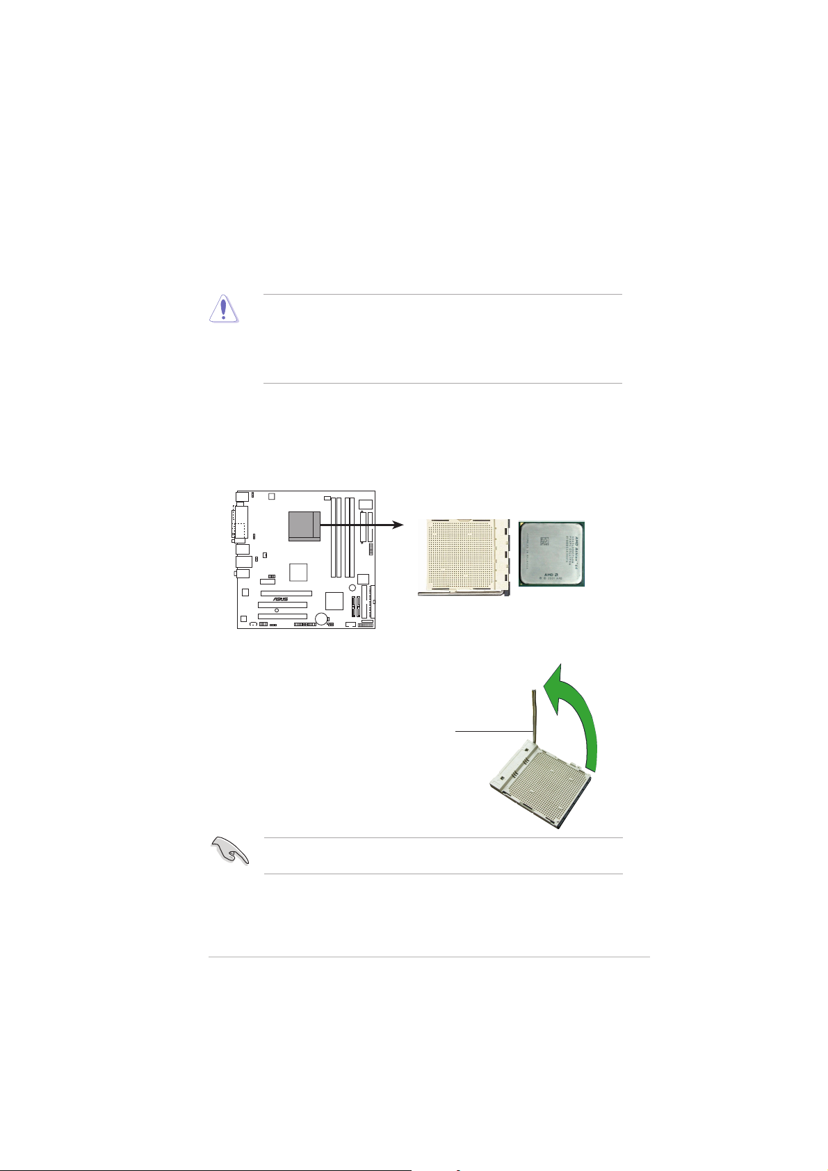
1. Locate the CPU socket on the motherboard.
M2NPV-MX
M2NPV-MX CPU Socket AM2
2. Unlock the socket by pressing
the lever sideways, then lift it up
to a 90°-100° angle.
Socket leverSocket lever
Socket lever
Socket leverSocket lever
Make sure that the socket lever is lifted up to 90°-100° angle, otherwise
the CPU does not fit in completely.
ASUS M2NPV-MXASUS M2NPV-MX
ASUS M2NPV-MX
ASUS M2NPV-MXASUS M2NPV-MX
1-91-9
1-9
1-91-9
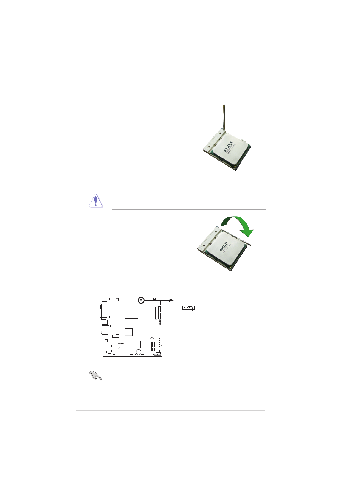
3. Position the CPU above the
®
socket such that the CPU corner
with the gold triangle matches
the socket corner with a small
triangle.
4. Carefully insert the CPU into the
socket until it fits in place.
Small triangleSmall triangle
Small triangle
Small triangleSmall triangle
Gold triangleGold triangle
Gold triangle
Gold triangleGold triangle
The CPU fits only in one correct orientation. DO NOT force the CPU into
the socket to prevent bending the pins and damaging the CPU!
5. When the CPU is in place, push
down the socket lever to secure
the CPU. The lever clicks on the
side tab to indicate that it is
locked.
6. Install a CPU heatsink and fan
following the instructions that
came with the heatsink package.
7. Connect the CPU fan cable to the CPU_FAN connector on the
motherboard.
1-101-10
1-10
1-101-10
CPU_FAN
GND
CPU FAN IN
CPU FAN PWR
CPU FAN PWM
M2NPV-MX
M2NPV-MX CPU fan connector
Do not forget to connect the CPU fan connector! Hardware monitoring
errors can occur if you fail to plug this connector.
Chapter 1: Product introductionChapter 1: Product introduction
Chapter 1: Product introduction
Chapter 1: Product introductionChapter 1: Product introduction
1.6.21.6.2
1.6.2
1.6.21.6.2
Installing the heatsink and fanInstalling the heatsink and fan
Installing the heatsink and fan
Installing the heatsink and fanInstalling the heatsink and fan
The AMD Athlon™ 64/Sempron™ processor require a specially designed
heatsink and fan assembly to ensure optimum thermal condition and
performance.
Make sure that you use only qualified heatsink and fan assembly.
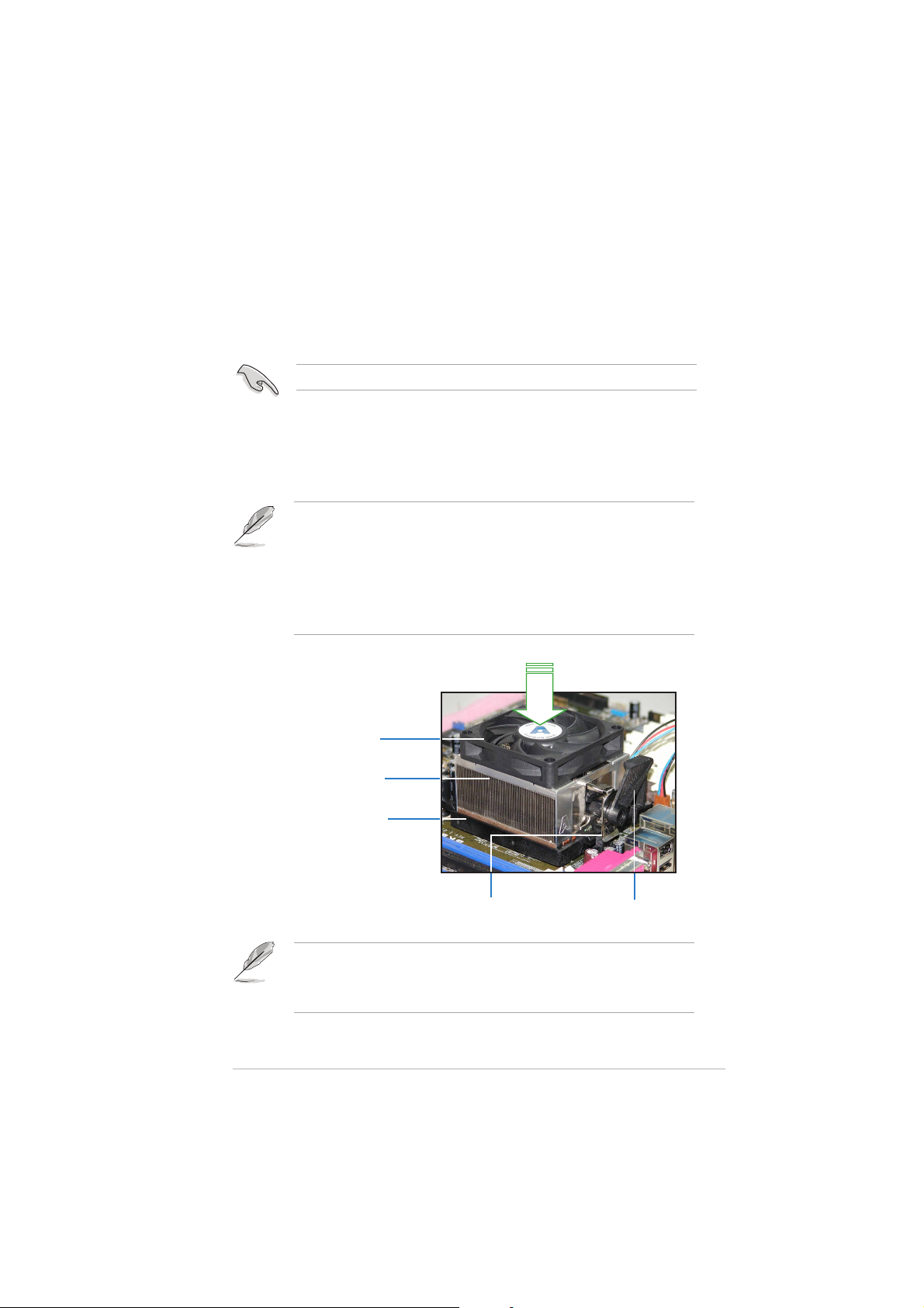
Follow these steps to install the CPU heatsink and fan.
1. Place the heatsink on top of the installed CPU, making sure that the
heatsink fits properly on the retention module base.
• The retention module base is already installed on the motherboard
upon purchase.
• You do not have to remove the retention module base when
installing the CPU or installing other motherboard components.
• If you purchased a separate CPU heatsink and fan assembly, make
sure that a Thermal Interface Material is properly applied to the CPU
heatsink or CPU before you install the heatsink and fan assembly.
CPU FanCPU Fan
CPU Fan
CPU FanCPU Fan
CPU HeatsinkCPU Heatsink
CPU Heatsink
CPU HeatsinkCPU Heatsink
Retention Module BaseRetention Module Base
Retention Module Base
Retention Module BaseRetention Module Base
Your boxed CPU heatsink and fan assembly should come with installation
instructions for the CPU, heatsink, and the retention mechanism. If the
instructions in this section do not match the CPU documentation, follow
the latter.
ASUS M2NPV-MXASUS M2NPV-MX
ASUS M2NPV-MX
ASUS M2NPV-MXASUS M2NPV-MX
Retention bracketRetention bracket
Retention bracket
Retention bracketRetention bracket
Retention bracket lockRetention bracket lock
Retention bracket lock
Retention bracket lockRetention bracket lock
1-111-11
1-11
1-111-11
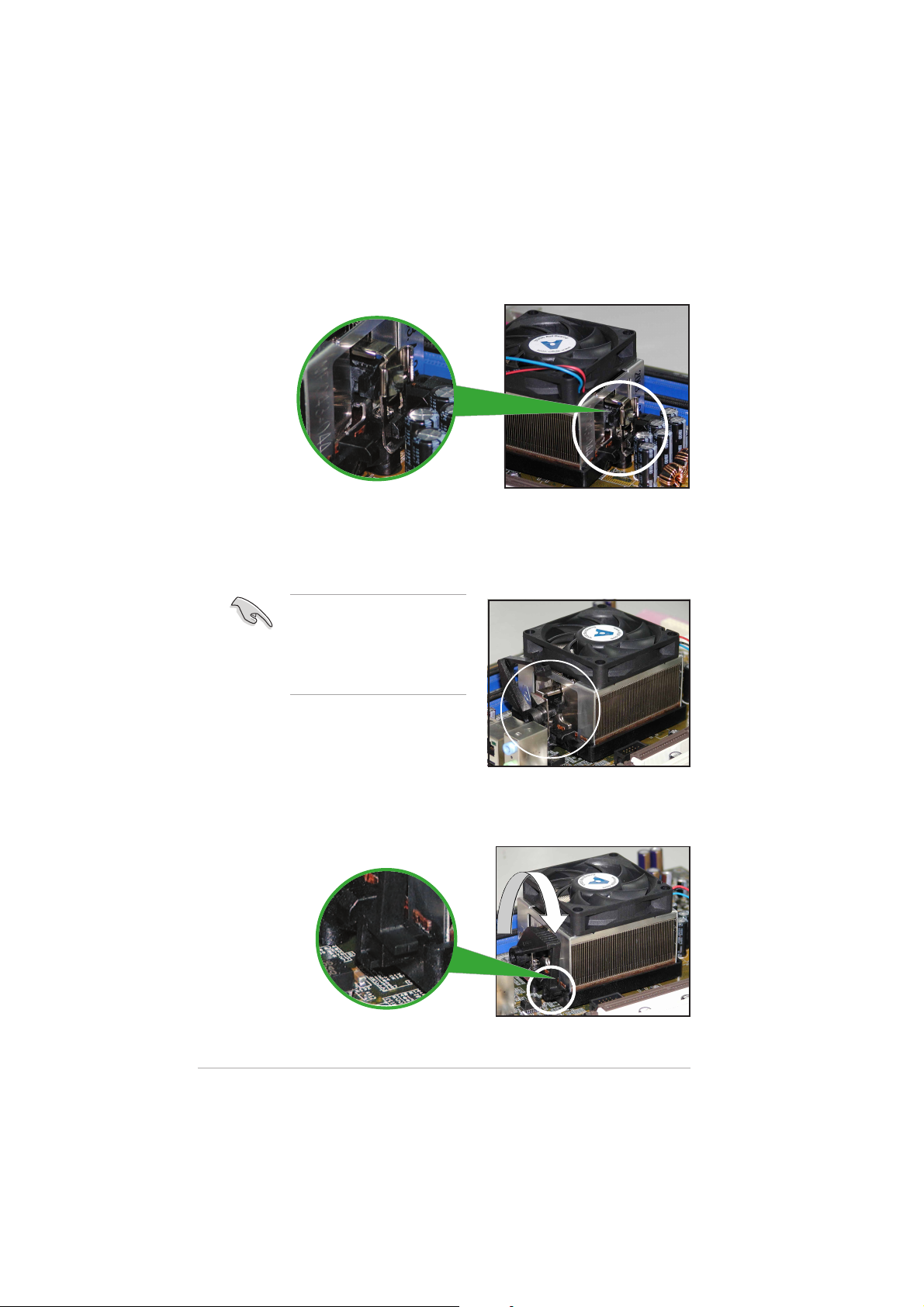
2. Attach one end of the retention bracket to the retention module
base.
3. Align the other end of the retention bracket (near the retention
bracket lock) to the retention module base. A clicking sound denotes
that the retention bracket is in place.
Make sure that the fan and
heatsink assembly perfectly
fits the retention mechanism
module base; otherwise, you
cannot snap the retention
bracket in place.
4. Push down the retention bracket lock on the retention mechanism to
secure the heatsink and fan to the module base.
1-121-12
1-12
1-121-12
Chapter 1: Product introductionChapter 1: Product introduction
Chapter 1: Product introduction
Chapter 1: Product introductionChapter 1: Product introduction
1.7 System memory
®
1.7.11.7.1
1.7.1
1.7.11.7.1
OverviewOverview
Overview
OverviewOverview
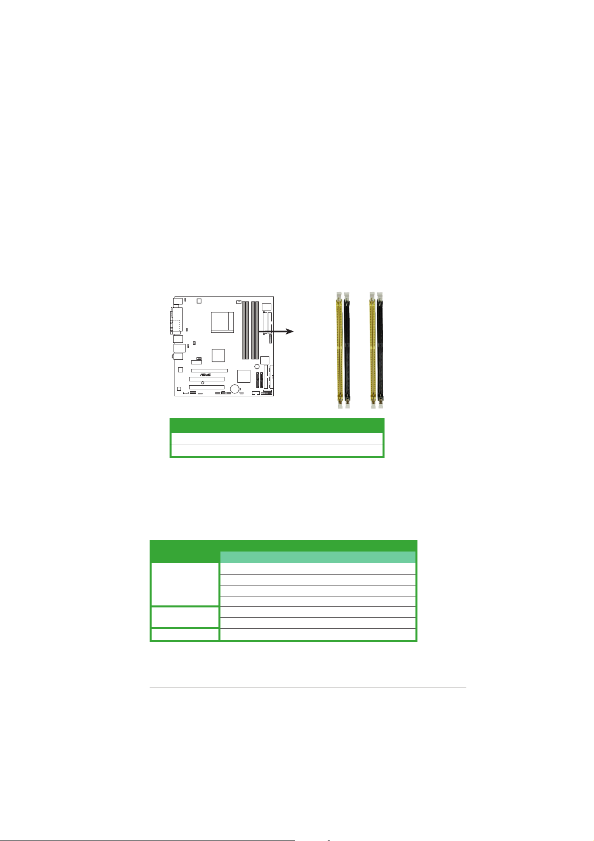
The motherboard comes with four Double Data Rate 2 (DDR2) Dual Inline
Memory Modules (DIMM) sockets.
A DDR2 module has the same physical dimensions as a DDR DIMM but has a
240-pin footprint compared to the 184-pin DDR DIMM. DDR2 DIMMs are
notched differently to prevent installation on a DDR DIMM socket.
The figure illustrates the location of the DDR2 DIMM sockets:
DIMM_A2
DIMM_A1
DIMM_B2
DIMM_B1
M2NPV-MX
M2NPV-MX 240-pin DDR2 DIMM sockets
1.7.21.7.2
1.7.2
1.7.21.7.2
ChannelChannel
Channel
ChannelChannel
Channel A DIMM_A1 and DIMM_A2
Channel B DIMM_B1 and DIMM_B2
Memory configurationsMemory configurations
Memory configurations
Memory configurationsMemory configurations
SocketsSockets
Sockets
SocketsSockets
You may install 256 MB, 512 MB, 1 GB, and 2 GB unbuffered ECC/non-ECC
DDR2 DIMMs into the DIMM sockets.
Recommended Memory ConfigurationsRecommended Memory Configurations
Recommended Memory Configurations
Recommended Memory ConfigurationsRecommended Memory Configurations
SocketsSockets
Sockets
SocketsSockets
ModeMode
Mode
ModeMode
Single Channel
Dual-channel (1)
Dual-channel (2)
ASUS M2NPV-MXASUS M2NPV-MX
ASUS M2NPV-MX
ASUS M2NPV-MXASUS M2NPV-MX
DIMM_A1 DIMM_A2 DIMM_B1 DIMM_B2
Populated - - -
- Populated - -
- - Populated -
- - - Populated
Populated - Populated -
- Populated - Populated
Populated Populated Populated Populated
1-131-13
1-13
1-131-13
* For dual-channel memory configuration (2), you may:
• install identical DIMMs in all four sockets OR
• install an identical DIMM pair in DIMM_A1 and DIMM_B1 (yellow
sockets) and another identical DIMM pair in DIMM_A2 and
DIMM_B2 (black sockets)
* Always use identical DDR2 DIMM pairs for dual-channel model. For
optimum compatibility, we recommend that you obtain memory
modules from the same vendor. Visit the ASUS website
(www.asus.com) for the latest Qualified Vendors List.
Important notice on installing Windows® XP 32-bit version
If you install Windows® XP 32-bit version Operating System (OS), the
limitation of this OS version is that it may reserve a certain amount of
memory space for system devices. We recommend that you install less
than 3 GB system memory if you would like to work under Windows
®
XP
32-bit version OS. The excess memory installation will not cause any
usage problem, but it will not give users the benefit of manipulating this
excess memory space.
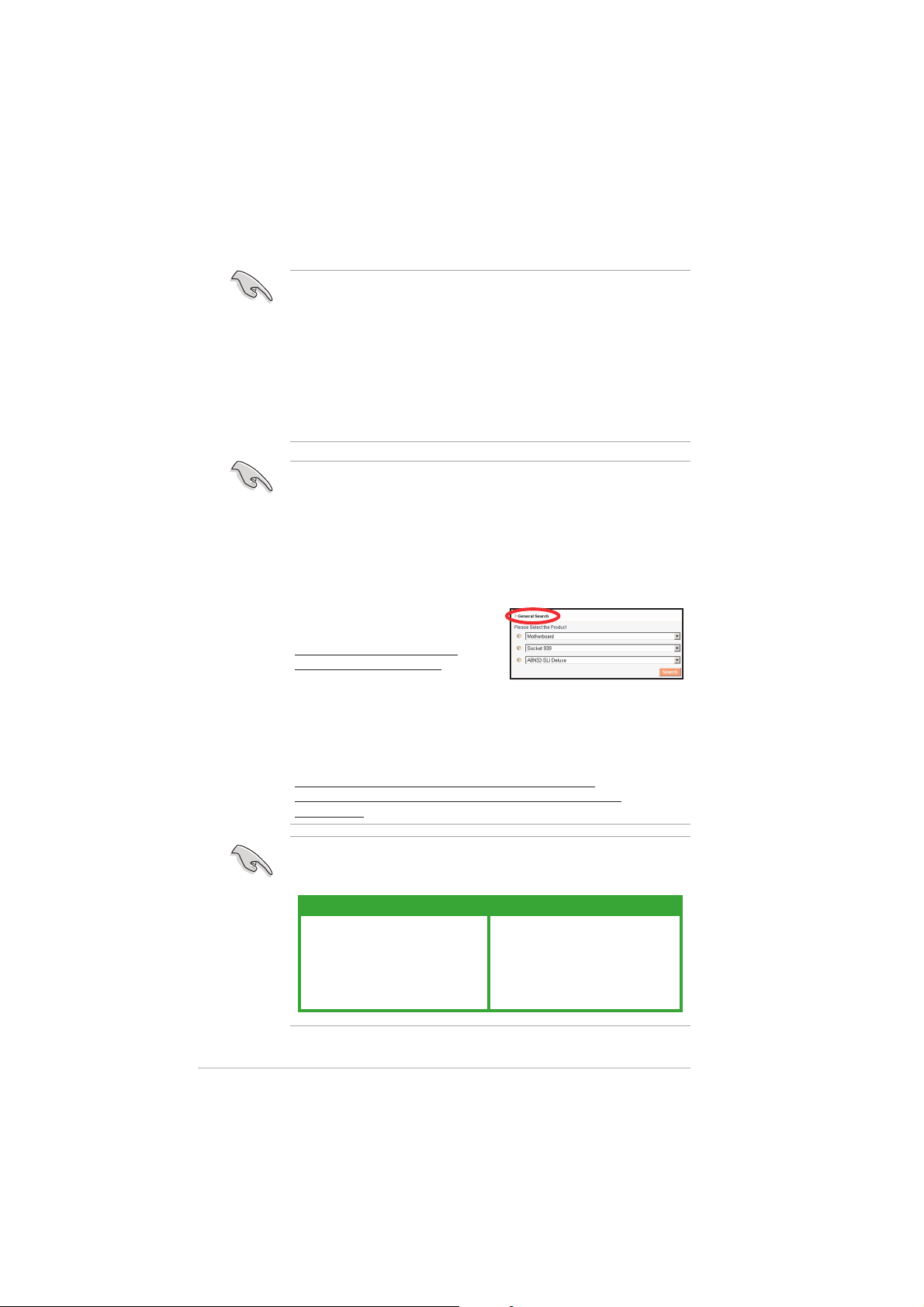
Visit the ASUS FAQ site for further
explanation:
http://support.asus.com/faq/
faq.aspx?SLanguage=en-us
General SearchGeneral Search
Under
General Search, make the
General SearchGeneral Search
selections as shown, then click
SearchSearch
Search. Click the article titled “
SearchSearch
memory size detected.memory size detected.
memory size detected.”
memory size detected.memory size detected.
4GB memory installed but less4GB memory installed but less
4GB memory installed but less
4GB memory installed but less4GB memory installed but less
1-141-14
1-14
1-141-14
You also may check the URLs below for third party comments on this
issue:
http://dlsvr01.asus.com/pub/ASUS/mb/4GB_Rev1.pdf
http://www.intel.com/support/motherboards/server/sb/cs-
016594.htm
This motherboard can support 8 GB physical memory on the operating
systems listed below. You may install a maximum of 2 GB DIMMs on each
slot.
32-bit32-bit
32-bit
32-bit32-bit
Windows® 2000 Advanced Server
Windows® Server 2003 Enterprise
Edition
Chapter 1: Product introductionChapter 1: Product introduction
Chapter 1: Product introduction
Chapter 1: Product introductionChapter 1: Product introduction
Windows® Server 2003 Standard
x64 Edition
Windows® XP Professtional x64
Edition
Windows® Server 2003 Enterprise
x64 Edition
64-bit64-bit
64-bit
64-bit64-bit
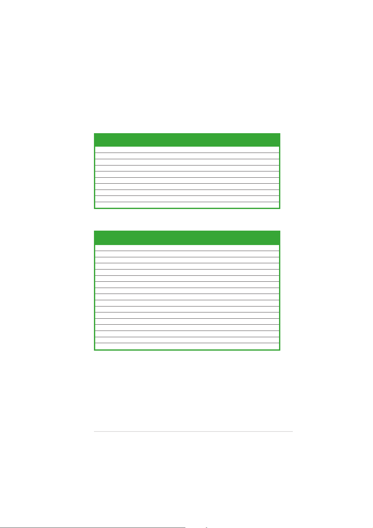
Qualified Vendors Lists (QVL)Qualified Vendors Lists (QVL)
Qualified Vendors Lists (QVL)
Qualified Vendors Lists (QVL)Qualified Vendors Lists (QVL)
DDR2-800 MHz capability
DIMM supportDIMM support
DIMM support
SizeSize
Size
SizeSize
VendorVendor
Vendor
VendorVendor
256 MB SAMSUNG K4T56083QF-ZCE7 – SS M378T3253FZ3-CE7 •
256 MB SAMSUNG K4T56083QF-ZCE7(ECC) – SS M391T3253FZ3-CE7 • •
512 MB SAMSUNG EDD339XX – SS M378T6553CZ3-CE7 • • •
512 MB Hynix HY5PS12821AFP-S6 – SS HYMP564U64AP8-S6 •
1024 MB Hynix HY5PS12821AFP-S6 – DS HYMP512U64AP8-S6 • •
512 MB MICRON 5JAIIZ9DQQ – SS MT8HTF6464AY-80EA3 • • •
1024 MB MICRON 5JAIIZ9DQQ – DS MT16HTF12864AY-80EA3 • •
1024 MB CORSAIR Heat-Sink Package – DS CM2X1024-6400PRO • •
256 MB A-DATA E2508AB-GE-E – SS M20EL6F3G3160A1D0Z •
256 MB A-DATA E2508AB-GE-E – SS M20EL6F3G3160A1D0Z •
ModelModel
Model
ModelModel
BrandBrand
Brand
BrandBrand
Side(s)Side(s)
Component Component
Side(s)
Component
Side(s)Side(s)
Component Component
DIMM supportDIMM support
A A
A
A A
DDR2-667 MHz capability
DIMM supportDIMM support
DIMM support
SizeSize
Size
SizeSize
VendorVendor
Vendor
VendorVendor
1024 MB KINGSTON E5108AE-6E-E – DS KVR667D2N5/1G • •
256 MB SAMSUNG K4T56083QF-ZCE6 – SS M378T3253FZ0-CE6 •
512 MB SAMSUNG K4T56083QF-ZCE6 – DS M378T6453FZ0-CE6 • •
256 MB SAMSUNG K4T51163QC-ZCE6 – SS M378T3354CZ0-CE6 • •
512 MB SAMSUNG ZCE6K4T51083QC – SS M378T6553CZ0-CE6 • •
256 MB Infineon HYB18T512160AF-3S – SS HYS64T32000HU-3S-A •
512 MB Infineon HYB18T512800AF3S – SS HYS64T64000HU-3S-A • •
512 MB Infineon HYB18T512800AF3S(ECC)– SS HYS72T64000HU-3S-A • • •
1024 MB Infineon HYB18T512800AF3S(ECC)– DS HYS72T128020HU-3S-A • •
512 MB Hynix HY5PS12821AFP-Y5 – SS HYMP564U64AP8-Y5 • • •
512 MB Hynix HY5PS12821AFP-Y4 – SS HYMP564U64AP8-Y4 • •
256 MB ELPIDA E2508AB-6E-E – SS EBE25UC8ABFA-6E-E • • •
512 MB ELPIDA E5108AB-6E-E – SS EBE51UD8AEFA-6E-E • • •
512 MB crucial Heat-Sink Package – DS BL6464AA664.16FB • • •
1024 MB crucial Heat-Sink Package – DS BL12864AA664.16FA • •
1024 MB crucial Heat-Sink Package – DS BL12864AL664.16FA • • •
1024 MB crucial Heat-Sink Package – DS BL12864AL663.16FA •
ModelModel
Model
ModelModel
BrandBrand
Brand
BrandBrand
Side(s)Side(s)
Side(s)
Side(s)Side(s)
Component Component
Component
Component Component
DIMM supportDIMM support
AA
A
AA
B B
B
B B
B B
B
B B
C C
C
C C
C C
C
C C
ASUS M2NPV-MXASUS M2NPV-MX
ASUS M2NPV-MX
ASUS M2NPV-MXASUS M2NPV-MX
1-151-15
1-15
1-151-15
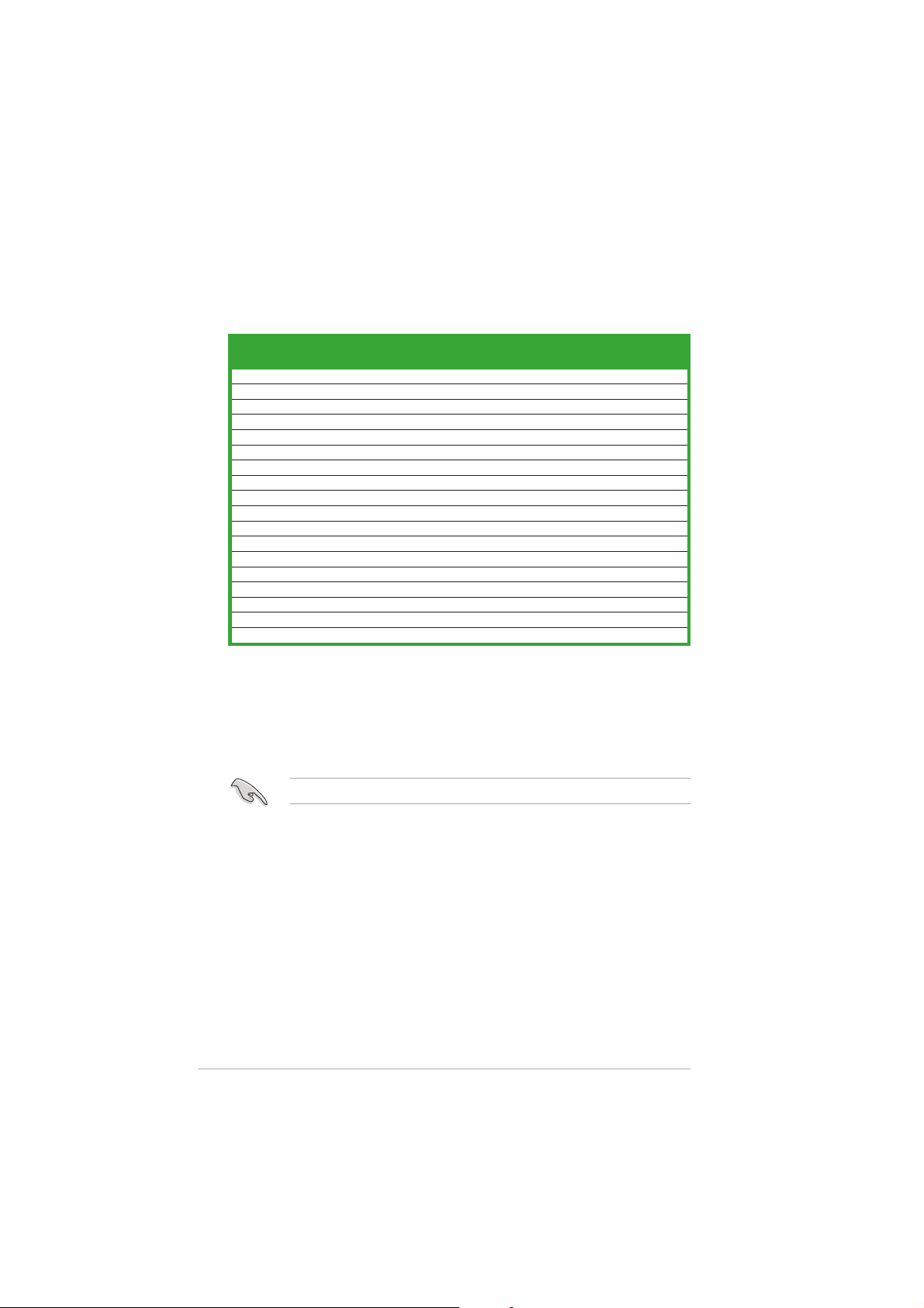
DDR2-533 MHz capability
DIMM supportDIMM support
DIMM support
SizeSize
Size
SizeSize
VendorVendor
Vendor
VendorVendor
256 MB KINGSTON E5116AF-5C-E – SS KVR533D2N4/256 • • •
512 MB KINGSTON HYB18T512800AF37 – SS KVR533D2N4/512 • • •
512 MB SAMSUNG K4T56083QF-GCD5 – DS M378T6453FG0-CD5 •
512 MB Infineon HYB18T512800AC37 – SS HYS64T64000GU-3.7-A • • •
256 MB Infineon HYB18T512160AF3.7 – SS HYS64T32000HU-3.7-A • • •
256 MB Infineon HYB18T5121608BF3.7 – SS HYS64T32000HU-3.7-B • • •
512 MB Infineon HYB18T512800BF37 – SS HYS64T64000HU-3.7-B • •
512 MB Hynix HY5PS12821F-C4 – SS HYMP564U648-C4 •
1024 MB Hynix HY5PS12821F-C4 – DS HYMP512U648-C4 • • •
512 MB Hynix HY5PS12821FP-C4(ECC) – SS HYMP564U728-C4 • • •
512 MB Hynix HY5PS12821AFP-C3 – SS HYMP564U64AP8-C3 • • •
512 MB ELPIDA E5108AB-5C-E – SS EBE51UD8ABFA-5C •
512 MB ELPIDA E5108AB-5C-E – SS EBE51UD8ABFA-5C-E • •
256 MB Apacer E5116AB-5C-E – SS 78.81077.420 • • •
256 MB KINGMAX E5116AB-5C-E – SS KLBB68F-36EP4 • •
1024 MB KINGMAX E5108AE-5C-E – DS KLBB48F-A8EB4 • •
512 MB KINGMAX KKEA88E4AAK-37 – SS KLBC28F-A8KE4 • •
512 MB Transcend K4T51083QB-GCD5 – SS TS64MLQ64V5J • • •
ModelModel
Model
ModelModel
BrandBrand
Brand
BrandBrand
Side(s)Side(s)
Side(s)
Side(s)Side(s)
Component Component
Component
Component Component
DIMM supportDIMM support
AA
A
AA
B B
B
B B
C C
C
C C
Side(s)Side(s)
Side(s):
Side(s)Side(s)
DIMM supportDIMM support
DIMM support:
DIMM supportDIMM support
AA
A - Supports one module inserted in any slot as Single-channel memory configuration.
AA
BB
B - Supports one pair of modules inserted into either the blue slots or the black slots as
BB
SSSS
S S - Single-sided
SSSS
DSDS
D S - Double-sided
DSDS
one pair of Dual-channel memory configuration.
CC
C - Supports 3 modules inserted into both the blue and black slots as two pairs of
CC
Dual-channel memory configuration.
Visit the ASUS website for the latest DDR2-800/667/533 MHz QVL.
1-161-16
1-16
1-161-16
Chapter 1: Product introductionChapter 1: Product introduction
Chapter 1: Product introduction
Chapter 1: Product introductionChapter 1: Product introduction
1.7.31.7.3
1.7.3
1.7.31.7.3
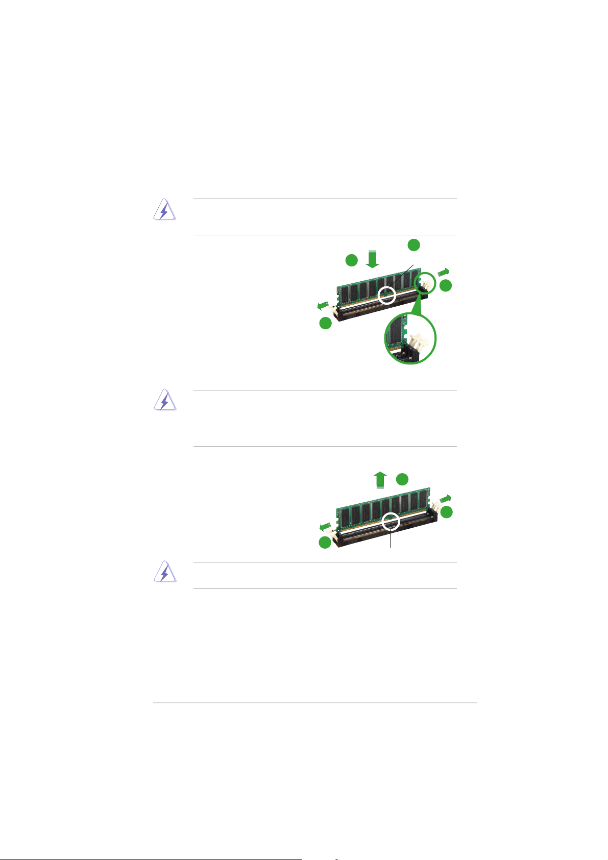
Installing a DIMMInstalling a DIMM
Installing a DIMM
Installing a DIMMInstalling a DIMM
Make sure to unplug the power supply before adding or removing DIMMs
or other system components. Failure to do so may cause severe damage
to both the motherboard and the components.
1. Unlock a DIMM socket by
pressing the retaining clips
outward.
2. Align a DIMM on the socket such
that the notch on the DIMM
matches the break on the
socket.
3. Firmly insert the DIMM into the
socket until the retaining clips
snap back in place and the DIMM
is properly seated.
• A DDR2 DIMM is keyed with a notch so that it fits in only one
direction. DO NOT force a DIMM into a socket to avoid damaging the
DIMM.
• The DDR2 DIMM sockets do not support DDR DIMMs. Do not install
DDR DIMMs to the DDR2 DIMM sockets.
2
DDR2 DIMM notchDDR2 DIMM notch
DDR2 DIMM notch
3
1
DDR2 DIMM notchDDR2 DIMM notch
1
Unlocked retaining clipUnlocked retaining clip
Unlocked retaining clip
Unlocked retaining clipUnlocked retaining clip
1.7.41.7.4
1.7.4
1.7.41.7.4
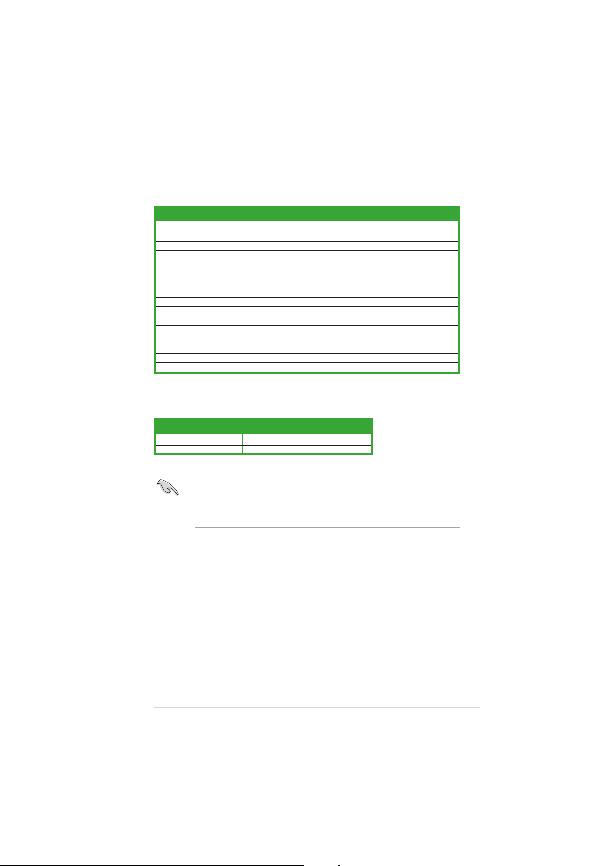
Removing a DIMMRemoving a DIMM
Removing a DIMM
Removing a DIMMRemoving a DIMM
To remove a DIMM:
1. Simultaneously press the
retaining clips outward to unlock
the DIMM.
Support the DIMM lightly with your fingers when pressing the retaining
clips. The DIMM might get damaged when it flips out with extra force.
2. Remove the DIMM from the socket.
ASUS M2NPV-MXASUS M2NPV-MX
ASUS M2NPV-MX
ASUS M2NPV-MXASUS M2NPV-MX
2
1
1
1
DDR2 DIMM notchDDR2 DIMM notch
DDR2 DIMM notch
DDR2 DIMM notchDDR2 DIMM notch
1-171-17
1-17
1-171-17

1.8 Expansion slots
In the future, you may need to install expansion cards. The following
sub-sections describe the slots and the expansion cards that they support.
Make sure to unplug the power cord before adding or removing
expansion cards. Failure to do so may cause you physical injury and
damage motherboard components.
1.8.11.8.1
1.8.1
1.8.11.8.1
To install an expansion card:
1. Before installing the expansion card, read the documentation that
2. Remove the system unit cover (if your motherboard is already
3. Remove the bracket opposite the slot that you intend to use. Keep
4. Align the card connector with the slot and press firmly until the card is
5. Secure the card to the chassis with the screw you removed earlier.
6. Replace the system cover.
1.8.21.8.2
1.8.2
1.8.21.8.2
After installing the expansion card, configure it by adjusting the software
settings.
1. Turn on the system and change the necessary BIOS settings, if any.
2. Assign an IRQ to the card. Refer to the tables on the next page.
3. Install the software drivers for the expansion card.
Installing an expansion cardInstalling an expansion card
Installing an expansion card
Installing an expansion cardInstalling an expansion card
came with it and make the necessary hardware settings for the card.
installed in a chassis).
the screw for later use.
completely seated on the slot.
Configuring an expansion cardConfiguring an expansion card
Configuring an expansion card
Configuring an expansion cardConfiguring an expansion card
See Chapter 2 for information on BIOS setup.
1-181-18
1-18
1-181-18
Chapter 1: Product introductionChapter 1: Product introduction
Chapter 1: Product introduction
Chapter 1: Product introductionChapter 1: Product introduction
Standard interrupt assignmentsStandard interrupt assignments
Standard interrupt assignments
Standard interrupt assignmentsStandard interrupt assignments
IRQIRQ
IRQ
IRQIRQ
0 1 System Timer
1 2 Keyboard Controller
2 – Re-direct to IRQ#9
3 11 IRQ holder for PCI steering*
4 12 Communications Port (COM1)*
5 13 IRQ holder for PCI steering*
6 14 Floppy Disk Controller
7 15 Printer Port (LPT1)*
8 3 System CMOS/Real Time Clock
9 4 IRQ holder for PCI steering*
10 5 IRQ holder for PCI steering*
11 6 IRQ holder for PCI steering*
12 7 PS/2 Compatible Mouse Port*
13 8 Numeric Data Processor
14 9 Primary IDE Channel
15 10 Secondary IDE Channel
PriorityPriority
Priority
PriorityPriority
Standard FunctionStandard Function
Standard Function
Standard FunctionStandard Function
* These IRQs are usually available for ISA or PCI devices.
IRQ assignments for this motherboardIRQ assignments for this motherboard
IRQ assignments for this motherboard
IRQ assignments for this motherboardIRQ assignments for this motherboard
AA
BB
CC
A
B
AA
BB
PCI slot 1 used — — —
PCI slot 2 — used — —
When using PCI cards on shared slots, ensure that the drivers support
“Share IRQ” or that the cards do not need IRQ assignments; otherwise,
conflicts will arise between the two PCI groups, making the system
unstable and the card inoperable.
DD
C
D
CC
DD
ASUS M2NPV-MXASUS M2NPV-MX
ASUS M2NPV-MX
ASUS M2NPV-MXASUS M2NPV-MX
1-191-19
1-19
1-191-19
 Loading...