


 Loading...
ESC4000A-E10
2U Rackmount Server
User Guide

E16748
First Edition
June 2020
Copyright © 2020 ASUSTeK COMPUTER INC. All Rights Reserved.
No part of this manual, including the products and software described in it, may be reproduced, transmitted, transcribed, stored in a retrieval system, or translated into any language in any form or by any means, except documentation kept by the purchaser for backup purposes, without the express written permission of ASUSTeK COMPUTER INC. (“ASUS”).
ASUS provides this manual “as is” without warranty of any kind, either express or implied, including but not limited to the implied warranties or conditions of merchantability or fitness for a particular purpose. In no event shall ASUS, its directors, officers, employees, or agents be liable for any indirect, special, incidental, or consequential damages (including damages for loss of profits, loss of business, loss of use or data, interruption of business and the like), even if ASUS has been advised of the possibility of such damages arising from any defect or error in this manual or product.
Specifications and information contained in this manual ae furnished for informational use only, and are subject to change at any time without notice, and should not be construed as a commitment by ASUS. ASUS assumes no responsibility or liability for any errors or inaccuracies that may appear in this manual, including the products and software described in it.
Product warranty or service will not be extended if: (1) the product is repaired, modified or altered, unless such repair, modification of alteration is authorized in writing by ASUS; or (2) the serial number of the product is defaced or missing.
Products and corporate names appearing in this manual may or may not be registered trademarks or copyrights of their respective companies, and are used only for identification or explanation and to the owners’ benefit, without intent to infringe.
ii

Contents
Safety information |
...................................................................................................... vi |
About this guide......................................................................................................... |
vii |
Chapter 1: Product Introduction
1.1 |
System package contents......................................................................... |
1-2 |
|
1.2 |
Serial number label..................................................................................... |
1-2 |
|
1.3 |
System specifications................................................................................ |
1-3 |
|
1.4 |
Front panel features................................................................................... |
1-5 |
|
1.5 |
Rear panel features.................................................................................... |
1-5 |
|
1.6 |
Internal features.......................................................................................... |
1-6 |
|
1.7 |
LED information.......................................................................................... |
1-7 |
|
|
1.7.1 |
Front panel LEDs......................................................................... |
1-7 |
|
1.7.2 |
LAN (RJ-45) LEDs....................................................................... |
1-8 |
|
1.7.3 |
HDD status LEDs......................................................................... |
1-9 |
|
1.7.4 |
Q-Code/Port 80 status LEDs..................................................... |
1-10 |
Chapter 2: Hardware Setup
2.1 |
Chassis cover............................................................................................. |
2-2 |
|
|
2.1.1 |
Air duct......................................................................................... |
2-4 |
2.2 |
Central Processing Unit (CPU).................................................................. |
2-5 |
|
|
2.2.1 |
Installing the CPU and heatsink................................................... |
2-5 |
2.3 |
System memory.......................................................................................... |
2-9 |
|
|
2.3.1 |
Overview...................................................................................... |
2-9 |
|
2.3.2 |
Memory Configurations................................................................ |
2-9 |
2.4 |
Hard disk drives........................................................................................ |
2-11 |
|
|
2.4.1 |
Installing the 3.5-inch SATA HDD/SAS HDD............................. |
2-11 |
|
2.4.2 |
Installing the 2.5-inch SSD/SATA HDD/SAS HDD/NVMe......... |
2-12 |
2.5 |
Expansion slots........................................................................................ |
2-13 |
|
|
2.5.1 |
The PCI Express riser card........................................................ |
2-13 |
|
2.5.2 |
Installing an ASUS PIKE II card................................................. |
2-16 |
|
2.5.3 |
Installing an M.2 expansion card............................................... |
2-22 |
|
2.5.4 |
Installing an M.2 (NGFF) card................................................... |
2-25 |
|
2.5.5 |
Configuring an expansion card.................................................. |
2-26 |
2.6 |
Cable connections.................................................................................... |
2-27 |
|
2.7 |
SATA/SAS backplane cabling................................................................. |
2-28 |
|
iii

Contents
2.8 |
Removable/optional components........................................................... |
2-29 |
|
|
2.8.1 |
Cable organizer metal cover...................................................... |
2-29 |
|
2.8.2 |
System fans............................................................................... |
2-30 |
|
2.8.3 |
Redundant power supply units.................................................. |
2-31 |
|
2.8.4 |
U.2 drives................................................................................... |
2-33 |
|
2.8.5 |
Installing Accelerators................................................................ |
2-35 |
Chapter 3: Installation Options
3.1 |
Friction Rail Kit........................................................................................... |
3-2 |
|
|
3.1.1 |
Attaching the rack rails ............................................................... |
3-2 |
Chapter 4: Motherboard Infomation
4.1 |
KRPG-U8 Motherboard layout |
...................................................................4-2 |
4.2 |
Jumpers....................................................................................................... |
4-4 |
4.3 |
Internal connectors.................................................................................... |
4-8 |
4.4 |
Onboard LEDs........................................................................................... |
4-16 |
Chapter 5: BIOS Setup
5.1 |
Managing and updating your BIOS........................................................... |
5-2 |
|
|
5.1.1 |
ASUS CrashFree BIOS 3 utility................................................... |
5-2 |
|
5.1.2 |
ASUS EZ Flash Utility.................................................................. |
5-3 |
|
5.1.3 |
BUPDATER utility........................................................................ |
5-4 |
5.2 |
BIOS setup program................................................................................... |
5-6 |
|
|
5.2.1 |
BIOS menu screen...................................................................... |
5-7 |
|
5.2.2 |
Menu bar...................................................................................... |
5-7 |
|
5.2.3 |
Menu items.................................................................................. |
5-8 |
|
5.2.4 |
Submenu items............................................................................ |
5-8 |
|
5.2.5 |
Navigation keys........................................................................... |
5-8 |
|
5.2.6 |
General help................................................................................ |
5-8 |
|
5.2.7 |
Configuration fields...................................................................... |
5-8 |
|
5.2.8 |
Pop-up window............................................................................ |
5-8 |
|
5.2.9 |
Scroll bar...................................................................................... |
5-8 |
5.3 |
Main menu................................................................................................... |
5-9 |
|
|
5.3.1 |
System Date [Day xx/xx/xxxx]..................................................... |
5-9 |
|
5.3.2 |
System Time [xx:xx:xx]................................................................ |
5-9 |
5.4 |
Performance Tuning menu...................................................................... |
5-10 |
|
iv

Contents
5.5 |
Advanced menu........................................................................................ |
5-12 |
|
|
5.5.1 |
Trusted Computing.................................................................... |
5-12 |
|
5.5.2 |
PSP Firmware Versions............................................................. |
5-13 |
|
5.5.3 |
APM Configuration..................................................................... |
5-13 |
|
5.5.4 |
Onboard LAN Configuration ..................................................... |
5-14 |
|
5.5.5 |
Serial Port Console Redirection................................................. |
5-15 |
|
5.5.6 |
CPU Configuration..................................................................... |
5-17 |
|
5.5.7 |
PCI Subsystem Settings............................................................ |
5-18 |
|
5.5.8 |
USB Configuration..................................................................... |
5-19 |
|
5.5.9 |
Network Stack Configuration..................................................... |
5-20 |
|
5.5.10 |
CSM Configuration.................................................................... |
5-21 |
|
5.5.11 |
NVMe Configuration.................................................................. |
5-22 |
|
5.5.12 |
SATA Configuration................................................................... |
5-22 |
|
5.5.13 |
AMD Mem Configuration Status................................................ |
5-23 |
|
5.5.14 |
iSCSI Configuration................................................................... |
5-23 |
5.6 |
Chipset menu............................................................................................ |
5-24 |
|
5.7 |
Security menu........................................................................................... |
5-25 |
|
5.8 |
Boot menu................................................................................................. |
5-28 |
|
5.9 |
Tool menu.................................................................................................. |
5-29 |
|
5.10 |
Save & Exit menu...................................................................................... |
5-30 |
|
5.11 |
AMD CBS menu........................................................................................ |
5-31 |
|
|
5.11.1 |
CPU Common Options.............................................................. |
5-31 |
|
5.11.2 |
DF Common Options................................................................. |
5-33 |
|
5.11.3 |
UMC Common Option............................................................... |
5-35 |
|
5.11.4 |
NBIO Common Options............................................................. |
5-40 |
|
5.11.5 |
NTB Common Options............................................................... |
5-44 |
5.12 |
Event Logs menu...................................................................................... |
5-45 |
|
|
5.12.1 Change Smbios Event Log Settings.......................................... |
5-45 |
|
|
5.12.2 View Smbios Event Log............................................................. |
5-46 |
|
5.13 |
Server Mgmt menu................................................................................... |
5-47 |
|
Chapter 6: Driver Installation
6.1 Running the Support DVD.........................................................................7-2
Appendix
KRPG-U8 block diagram......................................................................................... |
A-2 |
Notices ..................................................................................................................... |
A-3 |
ASUS contact information...................................................................................... |
A-6 |
v
Safety information
Electrical Safety
•Before installing or removing signal cables, ensure that the power cables for the system unit and all attached devices are unplugged.
•To prevent electrical shock hazard, disconnect the power cable from the electrical outlet before relocating the system.
•When adding or removing any additional devices to or from the system, ensure that the power cables for the devices are unplugged before the signal cables are connected. If possible, disconnect all power cables from the existing system before you add a device.
•If the power supply is broken, do not try to fix it by yourself. Contact a qualified service technician or your dealer.
Operation Safety
•Any mechanical operation on this server must be conducted by certified or experienced engineers.
•Before operating the server, carefully read all the manuals included with the server package.
•Before using the server, ensure all cables are correctly connected and the power cables are not damaged. If any damage is detected, contact your dealer as soon as possible.
•To avoid short circuits, keep paper clips, screws, and staples away from connectors, slots, sockets and circuitry.
•Avoid dust, humidity, and temperature extremes. Place the server on a stable surface.
This product is equipped with a three-wire power cable and plug for the user’s safety. Use the power cable with a properly grounded electrical outlet to avoid electrical shock.
Heavy System
CAUTION! This server system is heavy. Ask for assistance when moving or carrying the system.
vi

About this guide
Audience
This user guide is intended for system integrators, and experienced users with at least basic knowledge of configuring a server.
Contents
This guide contains the following parts:
1.Chapter 1: Product Introduction
This chapter describes the general features of the server, including sections on front panel and rear panel specifications.
2.Chapter 2: Hardware Setup
This chapter lists the hardware setup procedures that you have to perform when installing or removing system components.
3.Chapter 3: Installation Options
This chapter describes how to install optional components into the barebone server.
4.Chapter 4: Motherboard Information
This chapter gives information about the motherboard that comes with the server. This chapter includes the motherboard layout, jumper settings, and connector locations.
5.Chapter 5: BIOS Setup
This chapter tells how to change system settings through the BIOS Setup menus and describes the BIOS parameters.
6.Chapter 6: Driver Installation
This chapter provides instructions for installing the necessary drivers for different system components.
vii
Conventions
To ensure that you perform certain tasks properly, take note of the following symbols used throughout this manual.
DANGER/WARNING: Information to prevent injury to yourself when trying to complete a task.
CAUTION: Information to prevent damage to the components when trying to complete a task.
IMPORTANT: Instructions that you MUST follow to complete a task.
NOTE: Tips and additional information to help you complete a task.
Typography
Bold text |
Indicates a menu or an item to select. |
Italics |
Used to emphasize a word or a phrase. |
<Key> |
Keys enclosed in the less-than and greater-than |
|
sign means that you must press the enclosed key. |
|
Example: <Enter> means that you must press the |
|
Enter or Return key. |
<Key1>+<Key2>+<Key3> |
If you must press two or more keys simultaneously, |
|
the key names are linked with a plus sign (+). |
|
Example: <Ctrl>+<Alt>+<Del> |
Command |
Means that you must type the command exactly |
|
as shown, then supply the required item or value |
|
enclosed in brackets. |
|
Example: At the DOS prompt, |
|
type the command line: format A:/S |
References
Refer to the following sources for additional information, and for product and software updates.
1.ASUS Control Center (ACC) user guide
This manual tells how to set up and use the proprietary ASUS server management utility.
2.ASUS websites
The ASUS websites worldwide provide updated information for all ASUS hardware and software products. Refer to the ASUS contact information.
viii
Product Introduction |
1 |
This chapter describes the general features of the chassis kit. It includes sections on front panel and rear panel specifications.
1.1System package contents
Check your system package for the following items.
|
ESC4000A-E10 |
|
|
Chassis |
ASUS 2U Rackmount Chassis |
|
|
Motherboard |
ASUS KRPG-U8 Server Board |
|
|
|
1 x MB Support DVD |
|
1 x ACC instruction card |
|
1 x Bag of Screws |
|
2 x AC Power Cables |
Accessory box |
8 x 6+2-pin VGA Power cables |
|
4 x ASUS CPU 8-pin Power cables |
|
4 x GPU air ducts (for Nvidia/AMD cards) |
|
1 x CPU heatsink |
|
1 x Rail Kit |
|
|
Optional Items |
1 x OCP3.0 adapter card |
1 x Hyper M.2 adapter card |
If any of the above items is damaged or missing, contact your retailer.
1.2Serial number label
Before requesting support from the ASUS Technical Support team, you must take note of the product’s serial number containing 12 characters such as xxS0xxxxxxxx. See the figure below.
With the correct serial number of the product, ASUS Technical Support team members can then offer a quicker and satisfying solution to your problems.
ESC4000A-E10
xxS0xxxxxxxx
The serial number is printed on the Asset tag.
1-2 |
Chapter 1: Product Introduction |
1.3System specifications
The ASUS ESC4000A-E10 Series servers features the ASUS KRPG-U8 server board that supports AMD EPYC™ 7002 Series Processor Family.
Model Name |
ESC4000A-E10 |
|
||
Processor / System Bus |
AMD EPYC™ 7002 Series Processor Family (up to TDP 280W) |
|
||
|
Total Slots |
8 (8-channel per CPU, 8 DIMM per CPU) |
|
|
|
Capacity |
Up to 2TB |
|
|
Memory |
Memory Type |
DDR4 3200 RDIMM |
||
* Please refer to www.asus.com for latest memory AVL update |
|
|||
|
|
|||
|
Memory Size |
256GB, 128GB, 64GB, 32GB, 16GB* |
||
|
* Please refer to www.asus.com for latest memory AVL update |
|||
|
|
|||
|
Total PCI/PCI-X/ |
11 |
|
|
|
PCI-E/PIKE Slots |
|
||
|
|
Full-length/Full-height: |
||
Expansion |
|
4 x PCI-E 4.0 x16 link for double-deck GPU / Full Length cards |
||
|
or 8 x PCI-E 4.0 at x16 link with PLX SKU Board for single-deck |
|||
Slots |
|
|||
Slot Type |
GPU Cards |
|||
|
|
|
||
|
|
Half-length/Low-profile: |
||
|
|
2 x PCI-E 4.0 x16 for butterfly riser slot |
||
|
|
1 x PCI-E 4.0 x8 for internal HBA/RAID card |
|
|
Storage Bays |
|
8 x 2.5" or 3.5" Hot-swap Storage Device Bays |
||
|
(2 x NVMe as default; up to 4 x NVMe Supported) |
|||
|
|
|||
Networking |
LAN |
2 x 1Gb/s LAN ports (Intel® I350-AM2) |
|
|
1 x Dedicated management port |
|
|||
|
|
|||
Graphic |
VGA |
AST2500 64MB |
|
|
Security |
|
TPM2.0 |
|
|
Front I/O ports |
4 x USB 3.2 Gen 1 ports |
|
||
|
|
2 x USB 3.2 Gen 1 ports |
||
Rear I/O ports |
|
2 x Gigabit LAN ports (RJ45) |
||
|
1 x Management port (RJ45) |
|||
|
|
|||
|
|
1 x VGA port |
|
|
|
|
Front Switch/LED: |
||
|
|
1 x Power Switch/LED |
||
|
|
1 x Location Switch/LED |
||
|
|
1 x HDD Access LED |
||
|
|
1 x Message LED |
||
Switch/LED |
|
1 x Q-Code/Port 80 LED |
||
|
2 x LAN LED |
|||
|
|
|||
|
|
Rear Switch/LED: |
||
|
|
1 x Power switch/LED |
||
|
|
1 x Location LED |
||
|
|
1 x Message LED |
||
|
|
1 x HDD Access LED |
||
|
|
(continued on the next page) |
||
ASUS ESC4000A-E10 |
1-3 |
System specifications
Model Name |
ESC4000A-E10 |
||
OS Support |
|
Windows® Server 2019, RedHat® , SuSE®, Ubuntu, Vmware |
|
|
* Please find the latest OS support from http://www.asus.com/ |
||
|
|
||
|
Out of Band |
|
|
Management |
Remote |
On-Board ASMB9-iKVM for KVM-over-IP |
|
Solution |
Hardware |
|
|
|
Software |
ASUS Control Center (Classic) |
|
Dimension |
|
800mm x 440mm x 88mm (2U) |
|
|
31.50” x 17.22” x 3.46” |
||
|
|
||
Net Weight Kg |
|
||
(CPU, DRAM & HDD not |
34 kg |
||
included) |
|
|
|
Gross Weight Kg |
|
||
(CPU, DRAM & HDD not |
44 kg |
||
included, Packing include) |
|
||
Power Supply |
|
1+1 Redundant 1600W 80 PLUS Platinum Power Supply |
|
(following different |
|||
1+1 Redundant 2200W 80 PLUS Platinum Power Supply |
|||
configuration by region) |
|||
|
|||
|
|
Operation temperature: 10° ~ 35° |
|
Environment |
|
Non operation temperature: -40° ~ 70° |
|
|
|
Non operation humidity: 20% ~ 90% ( Non condensing) |
|
Always use PSUs with the same watt and power rating. Combining PSUs with different wattage (e.g. 1 x 1600 W + 1 x 2200 W) may yield unstable results and potential damage to your system.
Specifications are subject to change without notice.
1-4 |
Chapter 1: Product Introduction |
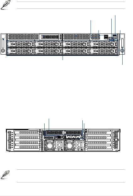
1.4Front panel features
The barebone server features a simple yet stylish front panel. The power and location buttons, LED indicators, and USB ports are located and easily accessible on the front panel.
Refer to the 1.7.1 Front panel LEDs section for the LED descriptions.
Q-code/Port 80 LED
Steel handle |
|
Internal SAS/HBA/Storage bracket |
|
Expansion card cage |
|||||||||||||||
|
|
|
|
|
|
|
|
|
|
|
|
|
|
|
|
|
|
|
|
|
|
|
|
|
|
|
|
|
|
|
|
|
|
|
|
|
|
|
|
|
|
|
|
|
|
|
|
|
|
|
|
|
|
|
|
|
|
|
|
|
|
|
|
|
|
|
|
|
|
|
|
|
|
|
|
|
|
|
|
|
|
|
|
|
|
|
|
|
|
|
|
|
|
|
|
|
|
|
|
|
|
|
|
|
|
|
|
|
|
|
|
|
|
|
|
|
|
|
|
|
|
|
|
|
|
|
|
|
|
|
|
|
|
|
|
|
|
|
|
|
|
|
|
|
|
|
|
|
|
|
|
|
|
|
|
|
|
|
|
|
|
|
|
|
|
|
|
|
|
|
|
|
|
|
|
|
|
|
|
|
|
|
|
|
|
|
|
|
|
|
|
|
|
|
|
|
|
|
|
|
|
|
|
|
|
|
|
|
|
|
|
|
|
|
|
|
|
|
|
USB 3.2 Gen 1 ports
Location button
Power button
USB 3.2 Gen 1 |
|
|
Front panel |
|||||
ports |
|
|
LED |
|||||
|
|
|
|
|
|
|
|
|
|
|
|
|
|
|
|
|
|
|
|
|
|
|
|
|
|
|
|
|
|
|
|
|
|
|
|
|
|
|
|
|
|
|
|
|
|
|
|
|
|
|
|
|
|
|
|
|
|
|
|
|
|
|
|
|
|
|
|
|
|
|
|
|
|
|
|
|
|
|
|
|
Hot-swap 3.5-inch storage bays |
Asset tag |
|
Steel handle
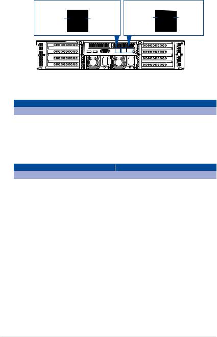
1.5Rear panel features
The expansion slots and system power socket is located on the rear panel of the server. The middle part includes the I/O shield with openings for the rear panel connectors on the motherboard.
Half-length / Low-profile expansion slot
VGA port
USB 3.0 ports
LAN port 2 LAN port 1
DM_LAN1*
|
|
|
|
|
|
|
|
|
|
|
|
|
|
|
|
|
|
|
|
|
|
|
|
|
|
|
|
|
|
|
|
|
|
|
|
|
|
|
|
|
|
|
|
|
|
|
|
|
|
|
|
|
|
|
|
|
|
|
|
|
|
|
|
|
|
|
|
|
|
|
|
|
|
|
|
|
|
|
|
|
|
|
|
|
|
|
|
|
|
|
|
|
|
|
|
|
|
|
|
|
|
|
|
|
|
|
|
|
|
|
|
|
|
|
|
|
|
|
|
|
|
|
|
|
|
|
|
|
|
|
|
|
|
|
|
|
|
|
|
|
|
|
|
|
|
|
|
|
|
|
|
|
|
|
|
|
|
|
|
|
|
|
|
|
|
|
|
|
|
|
|
|
|
|
|
|
|
|
|
|
|
|
|
|
|
|
|
|
|
|
|
|
|
|
|
|
|
|
|
|
|
|
|
|
|
|
|
|
|
|
|
|
|
|
|
|
|
|
|
|
|
|
|
|
|
|
|
|
|
|
|
|
|
|
|
|
|
|
|
|
|
|
|
|
|
|
|
|
|
|
|
|
|
|
|
|
|
|
|
|
|
|
|
|
|
|
|
|
|
|
|
|
|
|
|
|
|
|
|
|
|
|
|
|
|
|
|
|
|
|
|
|
|
|
|
|
|
|
|
|
|
|
|
|
|
|
|
|
|
|
|
|
|
|
|
|
|
|
|
|
|
|
|
|
|
|
|
|
|
|
|
|
|
|
|
|
|
|
|
|
|
|
|
|
|
|
|
|
|
|
|
|
|
|
|
|
|
|
|
|
|
|
|
|
|
|
|
|
|
|
|
|
|
|
|
|
|
|
|
|
|
|
|
|
|
|
|
|
|
|
|
|
|
|
|
|
|
|
|
4 Full-length |
|
Expansion slots |
Power cord |
|
connector and |
|
|
|
|
|
|
|
|
|
|
||||||||||||||||||||||||||||||||||
|
|
|
|
|
|
4 Full-length Expansion slots |
|||||||||||||||||||||||||||||||||||||||||||
|
|
|
|
|
|
|
|
|
Redundant power supply |
|
|
|
|
|
|
|
|
|
|
|
|||||||||||||||||||||||||||||
• The rear I/O ports do not appear on the rear panel if motherboard is not present.
• *The DM_LAN1 port is for ASUS ASMB9-iKVM controller only.
ASUS ESC4000A-E10 |
1-5 |

1.6Internal features
The barebone server includes the basic components as shown.
FAN7 |
|
|
|
FAN6 |
FAN5 |
FAN4 |
FAN3 |
FAN2 |
FAN1 |
1.Redundant power supply and power fan (hidden)
2.ASUS KRPG-U8 server board
3.System fans
4.SATA/SAS/U.2 backplane
5.Hot-swap Storage Device bays (SAS, SATA, and U.2)
6.PCI-E expansion boards (hidden)
7.PCI-E x32 slot with butterfly riser card
8.Internal SAS/HBA/ Storage bracket
A protection film is pre-attached to the front cover before shipping. Please remove the protection film before turning on the system for proper heat dissipation.
WARNING
HAZARDOUS MOVING PARTS
KEEP FINGERS AND OTHER BODY PARTS AWAY
1-6 |
Chapter 1: Product Introduction |
1.7LED information
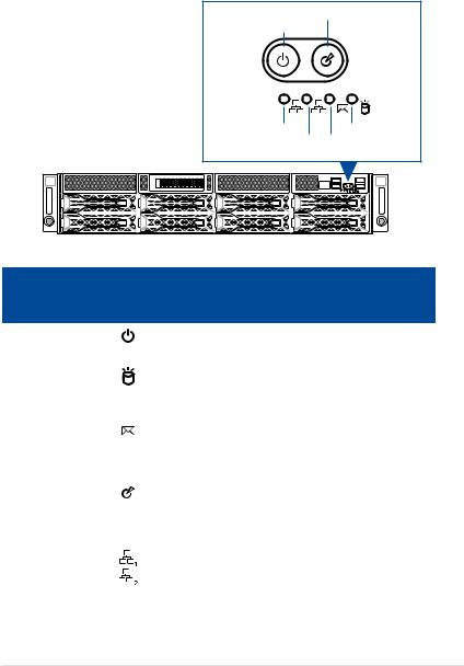
1.7.1Front panel LEDs
Location button with LED
Power button with LED
2 |
1 |
LAN2 LED |
HDD Access LED |
LAN1 LED |
Message LED |
|
|
|
|
|
|
|
|
|
|
|
|
|
|
|
|
|
|
|
|
|
|
|
|
|
|
|
|
|
|
|
|
|
|
|
|
|
|
|
|
|
|
|
|
|
|
|
|
|
|
|
|
|
|
|
|
|
|
|
|
|
|
|
|
|
|
|
|
|
|
|
|
|
|
|
|
|
|
|
|
|
|
|
|
|
|
|
|
|
|
|
|
|
|
|
|
|
|
|
|
|
|
|
|
|
|
|
|
|
|
|
|
|
|
|
|
|
|
|
|
|
|
|
|
|
|
|
|
|
|
|
|
|
|
|
|
|
|
|
|
|
|
|
|
|
|
|
|
|
|
|
|
|
|
|
|
|
|
|
|
|
|
|
|
|
|
|
|
|
|
|
|
|
|
|
|
|
|
|
|
|
|
|
|
|
|
|
|
|
|
|
|
|
|
|
|
|
|
|
|
|
|
|
|
|
|
|
|
|
|
|
|
|
|
|
|
|
|
|
|
|
|
|
|
|
|
|
|
|
|
|
|
|
|
|
|
|
|
|
|
|
|
|
|
|
|
|
|
|
|
|
|
|
|
|
|
|
|
|
|
|
|
|
|
|
|
|
|
|
|
|
|
|
|
|
|
|
|
|
|
|
|
|
|
|
|
|
|
|
|
LED |
Icon |
Display |
Description |
|||||||||||||||||||||||||
status |
||||||||||||||||||||||||||||
|
|
|
|
|
|
|
|
|
|
|
|
|
|
|
|
|||||||||||||
Power button with LED |
|
|
|
|
ON |
System power on |
||||||||||||||||||||||
|
|
|
|
|
|
|
|
|
|
|
|
|
|
|
|
|
|
|
||||||||||
HDD access LED |
|
|
|
|
OFF |
No activity |
||||||||||||||||||||||
|
|
|
|
|
|
|
|
|
|
|
|
|
|
|
|
|
|
|
|
|
|
|
|
|||||
|
|
|
|
Blinking |
Data activity |
|||||||||||||||||||||||
|
|
|
|
|
|
|
|
|
||||||||||||||||||||
|
|
|
|
|
|
|
|
|
|
|
|
|
|
|
|
|
|
|
||||||||||
Message LED |
|
|
|
|
OFF |
System is normal; no incoming event |
||||||||||||||||||||||
|
|
|
|
|
|
|
|
|
|
|
|
|
|
|
|
|
|
|
|
|
|
|
|
|||||
|
|
|
|
ON |
A hardware monitor event is indicated |
|||||||||||||||||||||||
|
|
|
|
|
|
|
|
|
||||||||||||||||||||
|
|
|
|
|
|
|
|
|
|
|
|
|
|
|
|
|
|
|
||||||||||
Location button with |
|
|
|
|
OFF |
Function off |
||||||||||||||||||||||
|
|
|
|
|
|
|
|
|
|
|
|
|
|
|
|
|
|
|
|
|
|
|
|
|||||
LED |
|
|
|
|
ON |
Location switch is pressed (Press the location switch |
||||||||||||||||||||||
|
|
|
|
|
|
|
|
|
||||||||||||||||||||
|
|
|
|
|
|
|
|
|
again to turn off) |
|||||||||||||||||||
|
|
|
|
|
|
|
|
|
|
|
|
|||||||||||||||||
|
|
|
|
|
|
|
|
|
|
|
|
|
|
|
|
|
|
|
||||||||||
|
|
|
|
|
|
|
|
|
OFF |
No LAN connection |
||||||||||||||||||
|
|
|
|
|
|
|
|
|
|
|
|
|
|
|
|
|||||||||||||
LAN LEDs |
|
|
|
|
Blinking |
LAN is transmitting or receiving data |
||||||||||||||||||||||
|
|
|
|
|
|
|
|
|
|
|
|
|
|
|
|
|
|
|
||||||||||
|
|
|
|
|
|
|
|
|
ON |
LAN connection is present |
||||||||||||||||||
|
|
|
|
|
|
|
|
|
|
|
|
|
|
|
|
|
|
|
|
|
|
|
|
|
|
|
|
|
ASUS ESC4000A-E10 |
1-7 |
1.7.2LAN (RJ-45) LEDs
ACT/LINK LED |
SPEED LED |
ACT/LINK LED |
SPEED LED |
LAN1/LAN2 LEDs
|
ACT/LINK LED |
|
|
SPEED LED |
|||||
|
Status |
|
Description |
|
Status |
|
|
Description |
|
|
OFF |
|
No link |
|
OFF |
|
|
10 Mbps connection |
|
|
GREEN |
|
Linked |
|
ORANGE |
|
|
100 Mbps connection |
|
|
|
|
|
|
|||||
|
BLINKING |
|
Data activity |
|
GREEN |
|
|
1 Gbps connection |
|
Dedicated Management LAN (for ASMB9 and DM_LAN1)
ACT/LINK LED |
|
SPEED LED |
||
Status |
Description |
Status |
|
Description |
OFF |
No link |
OFF |
|
10 Mbps connection |
ORANGE |
Linked |
ORANGE |
|
100 Mbps connection |
BLINKING |
Data activity |
GREEN |
|
1 Gbps connection |
1-8 |
Chapter 1: Product Introduction |
1.7.3HDD status LEDs
Red LED |
Green LED |
SATA/SAS HDD LED Description
GREEN |
ON |
SATA/SAS HDD power ON |
|
RED |
ON |
HDD has failed and should be swapped immediately |
|
GREEN/ |
Blinking |
RAID rebuilding |
|
RED |
|||
|
|
||
GREEN/ |
Blinking |
Locate |
|
RED |
|||
|
|
||
GREEN/ |
OFF |
HDD not found |
|
RED |
|||
|
|
||
GREEN |
Blinking |
Read/write data from/into the SATA/SAS HDD |
ASUS ESC4000A-E10 |
1-9 |

1.7.4Q-Code/Port 80 status LEDs
The Q-Code LED provides a 2-digit display that shows the status of your system. Refer to the Q-Code table of this user guide for more information about the 2-digit codes.
Q-Code table
Action |
PHASE |
POST CODE |
TYPE |
DESCRIPTION |
|
|
|
0x1 |
Progress |
First post code |
|
|
|
0x2 |
Progress |
Load BSP microcode |
|
SEC Start up |
Security Phase |
0x3 |
Progress |
Perform early platform Initialization |
|
0x4 |
Progress |
Set cache as ram for PEI phase |
|||
|
|
||||
|
|
0x5 |
Progress |
Establish Stack |
|
|
|
0x6 |
Progress |
CPU Early Initialization |
|
|
|
0x10 |
Progress |
PEI Core Entry |
|
|
PEI(Pre-EFI |
0x11 |
Progress |
PEI cache as ram CPU initial |
|
|
Initialization) phase |
0x15 |
Progress |
NB Initialization before installed memory |
|
|
|
0x19 |
Progress |
SB Initialization before installed memory |
|
|
|
0xB0 |
MRC Progress |
DIMM detect |
|
|
|
0xB1 |
MRC Progress |
DIMM clock Initialization |
|
|
|
0xB2 |
MRC Progress |
DIMM SPD data Initialization |
|
|
|
0xB3 |
MRC Progress |
DIMM global early |
|
|
|
0xB4 |
MRC Progress |
DIMM rank detect |
|
|
|
0xB5 |
MRC Progress |
DIMM channel early |
|
|
|
0xB6 |
MRC Progress |
DIMM DDRIO Initialization |
|
|
MRC Progress |
0xB7 |
MRC Progress |
DIMM channel training |
|
|
phase |
0xB8 |
MRC Progress |
DIMM Initialization throttling |
|
|
|
0xB9 |
MRC Progress |
memory BIST |
|
|
|
0xBA |
MRC Progress |
MEM memory Initialization |
|
|
|
0xBB |
MRC Progress |
DIMM DDR memory map |
|
|
|
0xBC |
MRC Progress |
RAS configuration |
|
|
|
0xBD |
MRC Progress |
Get Margins |
|
|
|
0xBE |
MRC Progress |
Memory SSA api Initialization |
|
|
|
0xBF |
MRC Progress |
MRC done |
|
|
|
0x32 |
Progress |
CPU POST-Memory Initialization |
|
|
|
0x33 |
Progress |
CPU Cache Initialization |
|
Quick VGA |
|
0x34 |
Progress |
Application Processor(s) (AP) Initialization |
|
|
0x35 |
Progress |
BSP Selection |
||
|
|
||||
|
|
0x36 |
Progress |
CPU Initialization |
|
|
|
0x37 |
Progress |
Pre-memory NB Initialization |
|
|
|
0x3B |
Progress |
Pre-memory SB Initialization |
|
|
|
0x4F |
Progress |
DXE Initial Program Load(IPL) |
|
|
|
0x60 |
Progress |
DXE Core Started |
|
|
|
0x61 |
Progress |
DXE NVRAM Initialization |
|
|
|
0x62 |
Progress |
SB run-time Initialization |
|
|
|
0x63 |
Progress |
CPU DXE Initialization |
|
|
DXE(Driver |
0x68 |
Progress |
PCI HB Initialization |
|
|
Execution |
|
|
|
|
|
0x69 |
Progress |
NB DXE Initialization |
||
|
Environment) phase |
||||
|
|
0x6A |
Progress |
NB DXE SMM Initialization |
|
|
|
0x70 |
Progress |
SB DXE Initialization |
|
|
|
0x71 |
Progress |
SB DXE SMM Initialization |
|
|
|
0x72 |
Progress |
SB DEVICES Initialization |
|
|
|
0x78 |
Progress |
ACPI Module Initialization |
|
|
|
0x79 |
Progress |
CSM Initialization |
|
|
|
0xD0 |
Progress |
CPU PM Structure Initialization |
|
|
|
0xD1 |
Progress |
CPU PM CSR programming |
|
|
|
0xD2 |
Progress |
CPU PM MSR programming |
|
|
|
0xD3 |
Progress |
CPU PM PSTATE transition |
|
|
|
0xD4 |
Progress |
CPU PM driver exit |
|
|
|
0xD5 |
Progress |
CPU PM On ready to boot event |
(continued on the next page)
1-10 |
Chapter 1: Product Introduction |

Q-Code table
Action |
PHASE |
POST CODE |
TYPE |
DESCRIPTION |
|
|
|
0x90 |
Progress |
BDS started |
|
|
|
0x91 |
Progress |
Connect device event |
|
|
|
0x92 |
Progress |
PCI Bus Enumeration |
|
|
|
0x93 |
Progress |
PCI Bus Enumeration |
|
|
|
0x94 |
Progress |
PCI Bus Enumeration |
|
|
|
0x95 |
Progress |
PCI Bus Enumeration |
|
|
|
0x96 |
Progress |
PCI Bus Enumeration |
|
|
|
0x97 |
Progress |
Console outout connect event |
|
|
|
0x98 |
Progress |
Console input connect event |
|
|
|
0x99 |
Progress |
AMI Super IO start |
|
|
|
0x9A |
Progress |
AMI USB Driver Initialization |
|
|
|
0x9B |
Progress |
AMI USB Driver Initialization |
|
|
|
0x9C |
Progress |
AMI USB Driver Initialization |
|
|
BDS(Boot Device |
0x9D |
Progress |
AMI USB Driver Initialization |
|
|
0xb2 |
Progress |
Legacy Option ROM Initialization |
||
|
Selection) phase |
||||
Normal boot |
0xb3 |
Progress |
Reset system |
||
|
|||||
|
|
0xb4 |
Progress |
USB hotplug |
|
|
|
0xb6 |
Progress |
NVRAM clean up |
|
|
|
0xb7 |
Progress |
NVRAM configuration reset |
|
|
|
0xA0 |
Progress |
IDE, AHCI Initialization |
|
|
|
0xA1 |
Progress |
IDE, AHCI Initialization |
|
|
|
0xA2 |
Progress |
IDE, AHCI Initialization |
|
|
|
0xA3 |
Progress |
IDE, AHCI Initialization |
|
|
|
0x00~0xFF |
Progress |
Wait BMC ready |
|
|
|
0xA8 |
Progress |
BIOS Setup Utility password verify |
|
|
|
0xA9 |
Progress |
BIOS Setup Utility start |
|
|
|
0xAB |
Progress |
BIOS Setup Utility input wait |
|
|
|
0xAD |
Progress |
Ready to boot event |
|
|
|
0xAE |
Progress |
Legacy boot event |
|
|
Operating system |
0xAA |
Progress |
APIC mode |
|
|
phase |
0xAC |
Progress |
PIC mode |
ASUS ESC4000A-E10 |
1-11 |

1-12 |
Chapter 1: Product Introduction |
Hardware Setup |
2 |
This chapter lists the hardware setup procedures that you have to perform when installing or removing system components.
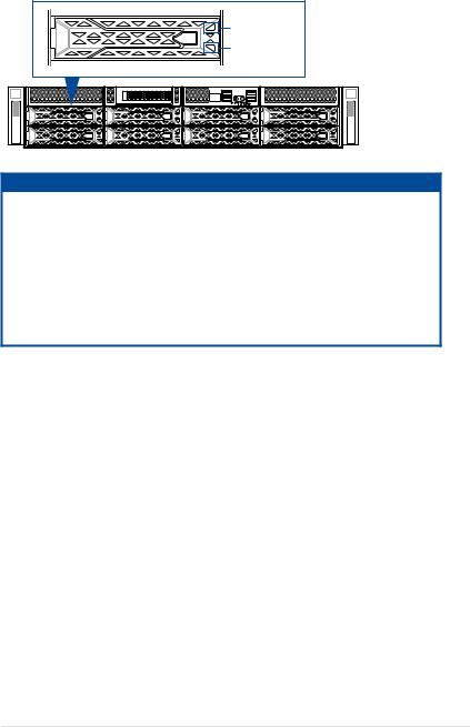
2.1Chassis cover
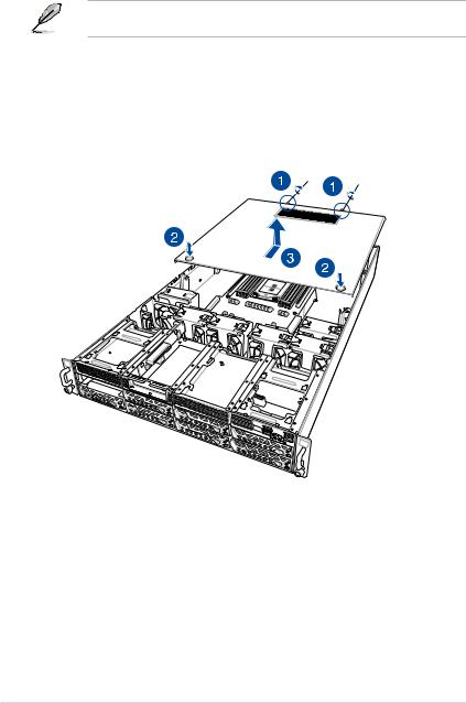
There are three parts of the chassis cover you may remove.
The diagrams in this section are for reference only. The system layout may vary with models, but the installation steps are the same for all models.
To remove the rear chassis cover:
1.Release the two (2) thumbscrews on the rear of the chassis.
2.Push and hold the cover buttons down, then slide the chassis cover towards the rear to disengage it from the chassis.
3.Lift the chassis cover to completely remove it from the chassis.
2-2 |
Chapter 2: Hardware Setup |
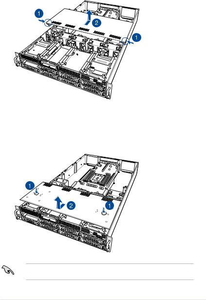
To remove the middle chassis cover:
1.Press the cover latches down on both sides of the middle chassis cover.
2.Lift the chassis cover to completely remove it from the chassis.
To remove the front chassis cover:
1.Push and hold the cover buttons down, then slide the chassis cover towards the front to disengage it from the chassis.
2.Lift the chassis cover to completely remove it from the chassis.
A protection film is pre-attached to the system cover before shipping. Please remove the protection film before turning on the system for proper heat dissipation.
ASUS ESC4000A-E10 |
2-3 |

2.1.1Air duct
The diagrams in this section are for reference only. The system layout may vary with models, but the installation steps are the same for all models.
To remove the air duct:
1.Remove the three screws as shown.
2.Lift the air duct to remove it from the chassis.
To reinstall the air duct:
1.Align and replace the air duct to the chassis ensuring that the screw holes on the air duct match the screw holes on chassis.
2.Secure the air duct to the chassis with three screws.
2-4 |
Chapter 2: Hardware Setup |
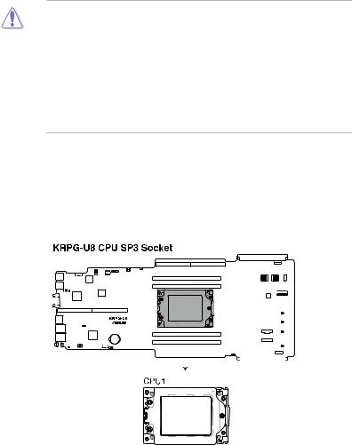
2.2Central Processing Unit (CPU)
The motherboard comes with a surface mount Socket SP3 socket designed for the AMD EPYC™ 7002 Series Family processors.
•Upon purchase of the motherboard, ensure that the PnP cap is on the socket and the socket contacts are not bent. Contact your retailer immediately if the PnP cap
is missing, or if you see any damage to the PnP cap/socket contacts/motherboard components. ASUS will shoulder the cost of repair only if the damage is shipment/ transit-related.
•Keep the cap after installing the motherboard. ASUS will process Return Merchandise Authorization (RMA) requests only if the motherboard comes with the cap on the InSocket SP3
•The product warranty does not cover damage to the socket contacts resulting from incorrect CPU installation/removal, or misplacement/loss/incorrect removal of the PnP cap.
2.2.1Installing the CPU and heatsink
1.Remove the rear chassis cover. For more information, see the section Chassis cover.
2.Remove the air duct. For more information, see the section Air Duct.
3.Locate the CPU socket on the motherboard.
|
|
|
|
|
|
|
|
|
|
|
|
|
|
|
|
|
|
|
|
|
|
|
|
|
|
|
|
|
|
|
|
|
|
|
|
|
|
|
|
|
|
|
|
|
|
|
|
|
|
|
|
|
|
|
|
|
|
|
|
|
|
|
|
|
|
|
|
|
|
|
|
|
|
|
|
|
|
|
|
|
|
|
|
|
|
|
|
|
|
|
|
|
|
|
|
|
|
|
|
|
|
|
|
|
|
|
|
|
|
|
|
|
|
|
|
|
|
|
|
|
|
|
|
|
|
|
|
|
|
|
|
|
|
|
|
|
|
|
|
|
|
|
|
|
|
|
|
|
|
|
|
|
|
|
|
|
|
|
|
|
|
|
|
|
|
|
|
|
|
|
|
|
|
|
|
|
|
|
|
|
|
|
|
|
|
|
|
|
|
|
|
|
|
|
|
|
|
|
|
|
|
|
|
|
|
|
|
|
|
|
|
|
|
|
|
|
|
|
|
|
|
|
|
|
|
|
|
|
|
|
|
|
|
|
|
|
|
|
|
|
|
|
|
|
|
|
|
|
|
|
|
|
|
|
|
|
|
|
|
|
|
|
|
|
|
|
|
|
|
|
|
|
|
|
|
|
|
|
|
|
|
|
|
|
|
|
|
|
|
|
|
|
|
|
|
|
|
|
|
|
|
|
|
|
|
|
|
|
|
|
|
|
|
|
|
|
|
|
|
|
|
|
|
|
|
|
|
|
|
|
|
|
|
|
|
|
|
|
|
|
|
|
|
|
|
|
|
|
|
|
|
|
|
|
|
|
|
|
|
|
|
|
|
|
|
|
|
|
|
|
|
|
|
|
|
|
|
|
|
|
|
|
|
|
|
|
|
|
|
|
|
|
|
|
|
|
|
|
|
|
|
|
|
|
|
|
|
|
|
|
|
|
|
|
|
|
|
|
|
|
|
|
|
|
|
|
|
|
|
|
|
|
|
|
|
|
|
|
|
|
|
|
|
|
|
|
|
|
|
|
|
|
|
|
|
|
|
|
|
|
|
|
|
|
|
|
|
|
|
|
|
|
|
|
|
|
|
|
|
|
|
|
|
|
|
|
|
|
|
|
|
|
|
|
|
|
|
|
|
|
|
|
|
|
|
|
|
|
|
|
|
|
|
|
|
|
|
ASUS ESC4000A-E10 |
2-5 |
|||||||||||||||||||||||||||||||||||
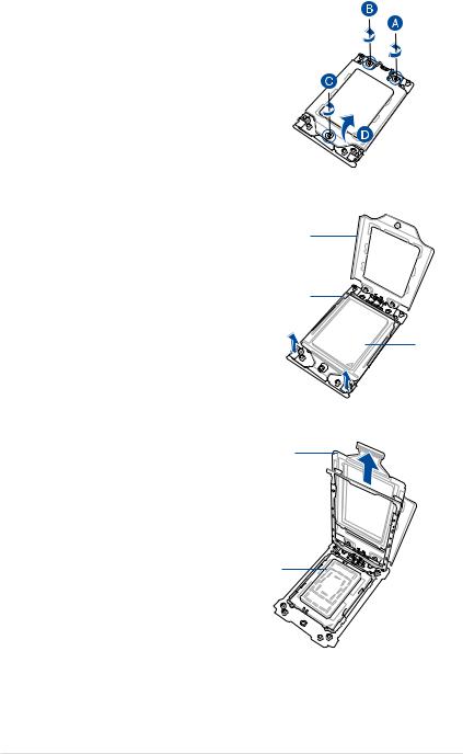
4.Loosen each screw one by one in the sequence shown on the socket to open the load plate.
5.Slightly lift open the rail frame.
Load plate
Rail frame |
External cap
6.Slide the external cap out of the rail frame.
External cap
Rail frame 
PnP cap
2-6 |
Chapter 2: Hardware Setup |
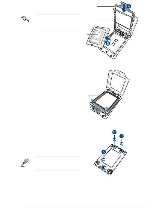
7.Slide the carrier frame with CPU into the rail frame, then remove the PnP cap.
The carrier frame with CPU fits in only one correct orientation. DO NOT force the carrier frame with CPU into the rail frame.
Carrier frame with CPU
Rail frame
PnP cap
8. Gently push the rail frame just enough to let it sit on top of the CPU socket.
Carrier frame with CPU
9. Close the load plate just enough to let it sit on top of the CPU, then secure each screw one by one in the sequence shown on the socket to completely secure the load plate.
The load plate screws are T20 models. A torque value of 14+/-1.0 inch-lbf is recommended.
ASUS ESC4000A-E10 |
2-7 |
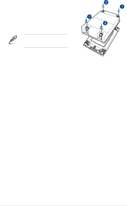
10.Twist each of the four screws with a screwdriver in the order shown in the illustration just enough to attach the heatsink to the motherboard. When the four screws are attached, tighten them one by one in a the same diagonal sequence to completely secure the heatsink.
The heatsink screws are T20 models. A torque value of 14+/-1.0 inch-lbf is recommended.
11.Reinstall the air duct. For more information, see the section Air Duct.
2-8 |
Chapter 2: Hardware Setup |
2.3System memory
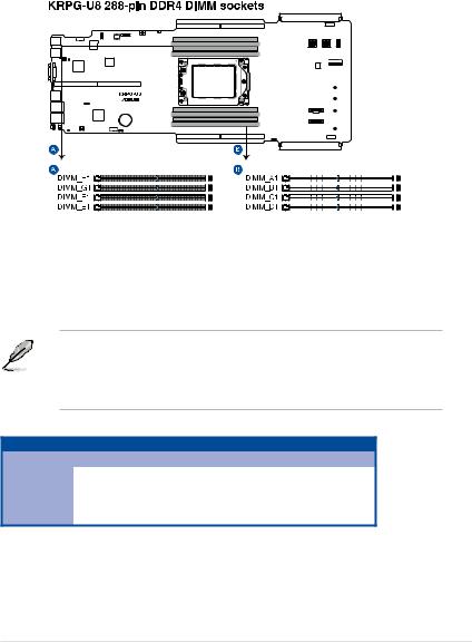
2.3.1Overview
The motherboard comes with eight (8) Double Data Rate 4 (DDR4) Dual Inline Memory Modules (DIMM) sockets.
The figure illustrates the location of the DDR4 DIMM sockets:
2.3.2Memory Configurations
You may install 16 GB, 32 GB, 64 GB, 128 GB, 256 GB DDR4 RDIMMs into the DIMM sockets using the memory configurations in this section.
• Refer to ASUS Server AVL for the updated list of compatible DIMMs.
• Always install DIMMs with the same CAS latency. For optimum compatibility, it is recommended that you obtain memory modules from the same vendor.
• Start installing the DIMMs into the second slots (such as DIMM_A2 , DIMM_B2, etc.)
1 CPU Configuration
|
A1 |
B1 |
C1 |
D1 |
E1 |
F1 |
G1 |
H1 |
1 DIMM |
|
|
• |
|
|
|
|
|
2 DIMMs |
|
|
• |
• |
|
|
|
|
4 DIMMs |
|
|
• |
• |
|
|
• |
• |
8 DIMMs |
• |
• |
• |
• |
• |
• |
• |
• |
ASUS ESC4000A-E10 |
2-9 |
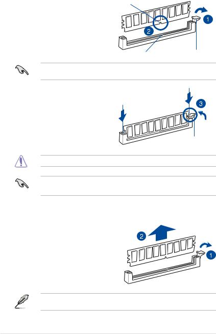
2.3.3Installing a DIMM on a single clip DIMM socket
1. |
Press the retaining clip outward to unlock DIMM notch |
|
|
a DIMM socket. |
|
2. |
Align a DIMM on the socket such that the |
|
|
notch on the DIMM matches the DIMM |
|
|
slot key on the socket. |
|
|
DIMM slot key |
Unlocked retaining clip |
|
A DIMM is keyed with a notch so that it fits in only one direction. DO NOT force a DIMM into |
|
|
a socket in the wrong direction to avoid damaging the DIMM. |
|
3. |
Hold the DIMM on both ends, then insert |
|
|
the DIMM vertically into the socket. |
|
|
Apply force to both ends of the DIMM |
|
|
simultaneously until the retaining clip |
|
|
snaps back into place, and the DIMM |
|
|
cannot be pushed in any further to ensure |
|
|
proper sitting of the DIMM. |
|
|
|
Locked Retaining Clip |
Always insert the DIMM into the socket VERTICALLY to prevent damage to the DIMM notch.
•To install two or more DIMMs, refer to the user guide bundled in the motherboard package.
•Refer to www.asus.com for vendor lists of the memory modules.
Removing a DIMM from a single clip DIMM socket
1.Press the retaining clip outward to unlock the DIMM.
2. Remove the DIMM from the socket.
Support the DIMM lightly with your fingers when pressing the retaining clips. The DIMM might get damaged when it flips out with extra force.
2-10 |
Chapter 2: Hardware Setup |
Loading...