

Page 1
CG64G1 F
1
3
42
CG64G1 X F
CG64G1 EX
CG640SG1 EX
GB
English
Operating Instructions
COOKER AND OVEN
Contents
Operating Instructions,1
Description of the appliance-Control Panel,1
Description of the appliance-Overall view,2
Installation,3
Start-up and use,8
Cooking modes,9
Precautions and tips,11
Care and maintenance,12
Assistance,12
Français
FR
Mode d’emploi
CUISINIERE ET FOUR
GB
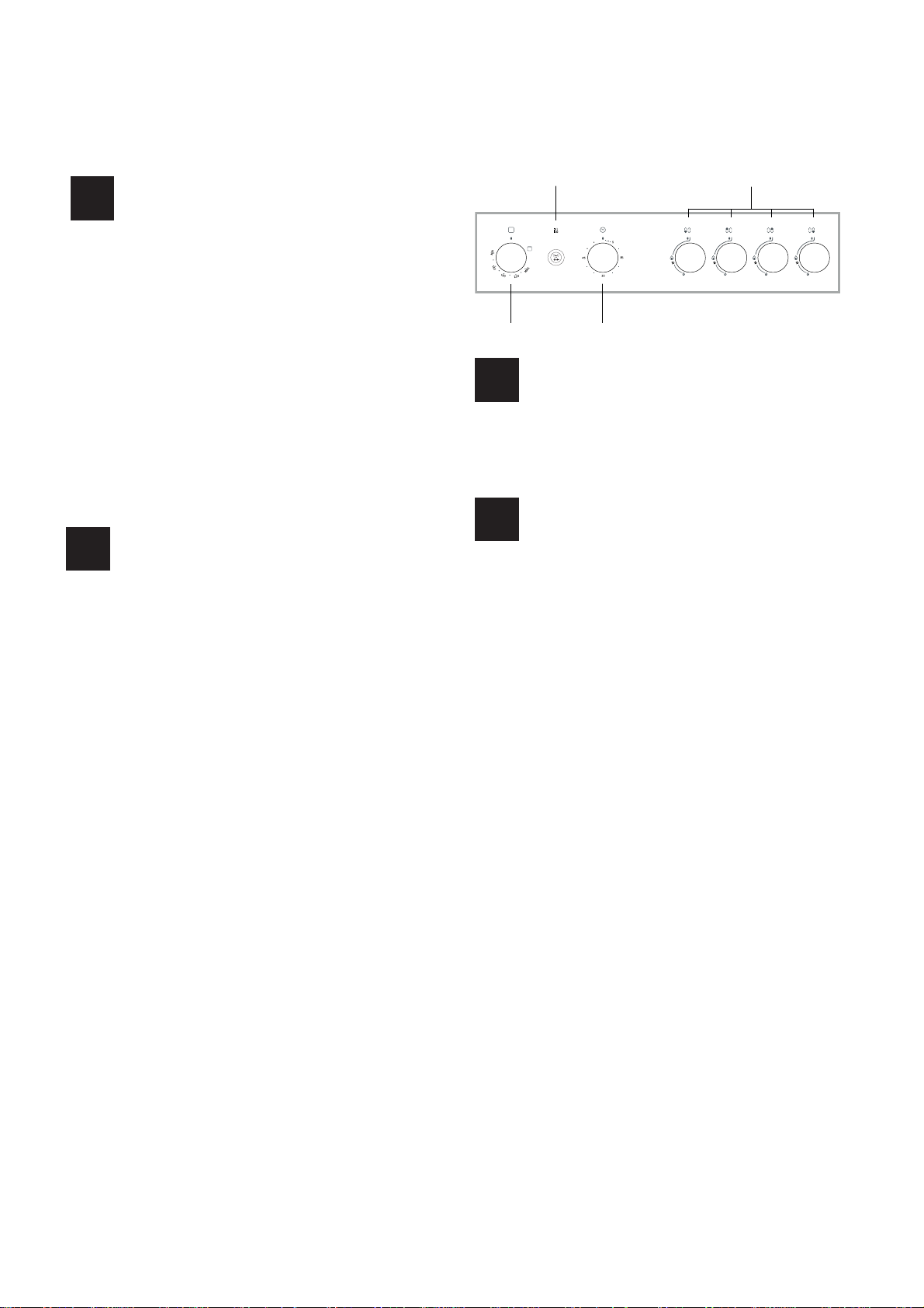
1.OVEN CONTROL knob
2.OVEN LIGHT / ROTISSERIE button
3.TIMER knob
4. Hob BURNER control knob
FR
1.Manette du four
2.Bouton ECLAIRAGE/ TOURNEBROCHE
3.Manette du MINUTEUR
4.Manette BRULEURS
Description of the appliance
Control panel
Description de l’appareil
Tableau de bord
Sommaire
Mode d’emploi,1
Description de l’appareil-Tableau de bord, 1
Description de l’appareil-Vue d’ensemble, 2
Installation,13
Mise en marche et utilisation,18
Utilisation du plan de cuisson,19
Précautions et conseils, 21
Nettoyage et entretien,22
Assistance,22
Page 2
14
1
2
3
4
5
6
GB
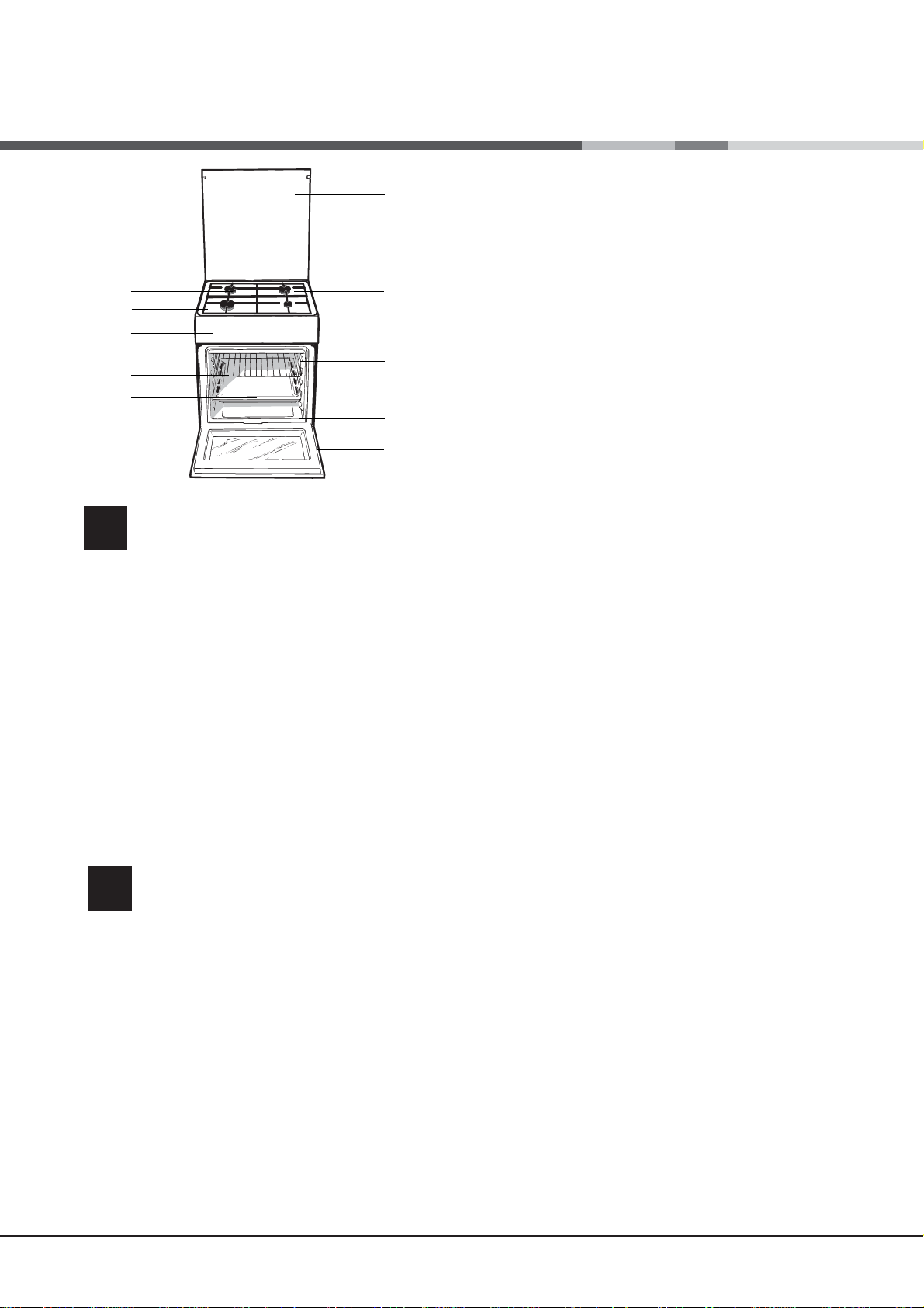
Description of the appliance
Overall view
1. Hob burner
2.Hob Grid
3.Control panel
4.Sliding grill rack
5.DRIPPING pan
6.Adjustable foot
7.Containment surface for spills
8.GUIDE RAILS for the sliding racks
9.position 5
10.position 4
11.position 3
12.position 2
13.position 1
14. Glass Cover *(Available only on certain
models)
7
8
9
10
11
12
13
6
Description de l’appareil
FR
Vue d’ensemble
1. Brûleur à gaz
2.Grille du plan de cuisson
3. Tableau de bord
4. Support GRILLE
5. Support LECHEFRITE
6.Pied de réglage
7. Plateau du plan de cuisson
8. GLISSIERES de coulissement
9. niveau 5
10. niveau 4
11. niveau 3
12. niveau 2
13. niveau 1
14 Couvercle en verre (N’existe que sur certains modèles)
2
Page 3
Installation
! Before operating your new appliance please read
this instruction booklet carefully. It contains important
information concerning the safe installation and
operation of the appliance.
! Please keep these operating instructions for future
reference. Make sure that the instructions are kept with
the appliance if it is sold, given away or moved.
! The appliance must be installed by a qualified
professional according to the instructions provided.
! Any necessary adjustment or maintenance must be
performed after the cooker has been disconnected
from the electricity supply.
Room ventilation
The appliance may only be installed in permanentlyventilated rooms, according to current national
legislation. The room in which the appliance is installed
must be ventilated adequately so as to provide as
much air as is needed by the normal gas combustion
3
process (the flow of air must not be lower than 2 m
/h
per kW of installed power).
The air inlets, protected by grilles, should have a duct
2
with an inner cross section of at least 100 cm
and
should be positioned so that they are not liable to even
partial obstruction (see gure A).
These inlets should be enlarged by 100% - with a
2
minimum of 200 cm
- whenever the surface of the
hob is not equipped with a flame failure safety device.
When the flow of air is provided in an indirect manner
from adjacent rooms (see gure B), provided that these
are not communal parts of a building, areas with
increased fire hazards or bedrooms, the inlets should
be fitted with a ventilation duct leading outside as
described above.
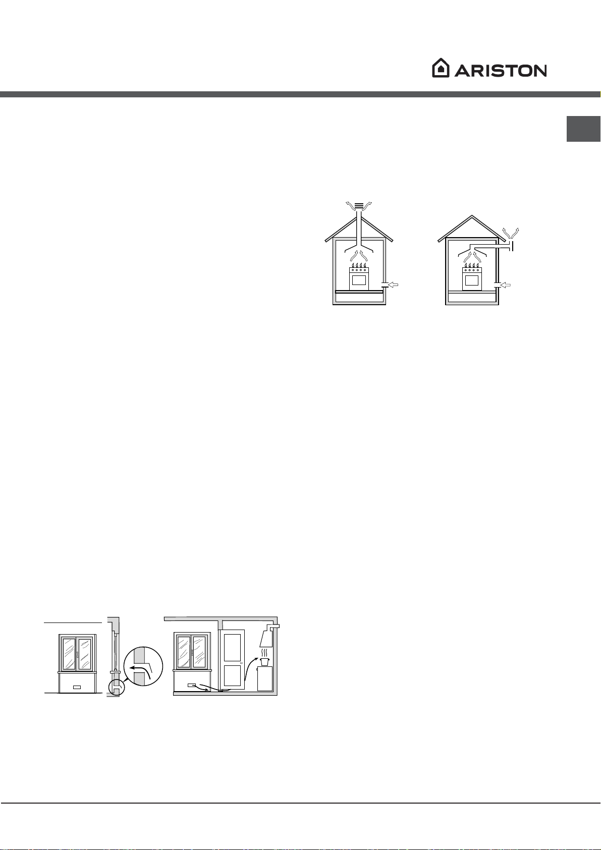
Disposing of combustion fumes
The disposal of combustion fumes should be
guaranteed using a hood connected to a safe and
efficient natural suction chimney, or using an electric
fan that begins to operate automatically every time the
appliance is switched on (see gure).
Fumes channelled
straight outside
Fumes channelled through
a chimney or a branched
flue system (reserved for
cooking appliances)
! The liquefied petroleum gases are heavier than air
and collect by the floor, therefore all rooms containing
LPG cylinders must have openings leading outside so
that any leaked gas can escape easily.
LPG cylinders, therefore, whether partially or
completely full, must not be installed or stored in rooms
or storage areas that are below ground level (cellars,
etc.). Only the cylinder being used should be stored
in the room; this should also be kept well away from
sources of heat (ovens, chimneys, stoves) that may
cause the temperature of the cylinder to rise above
50°C.
Positioning and levelling
! It is possible to install the appliance alongside
cupboards whose height does not exceed that of the
hob surface.
GB
Adjacent room Room requiring
ventilation
A B
A
Ventilation opening
for comburent air
Increase in the gap
between the door and
the flooring
! After prolonged use of the appliance, it is advisable to
open a window or increase the speed of any fans used.
! Make sure that the wall in contact with the back of
the appliance is made from a non-flammable, heatresistant material (T 90°C).
To install the appliance correctly:
• Place it in the kitchen, dining room or the bed-sit (not
in the bathroom).
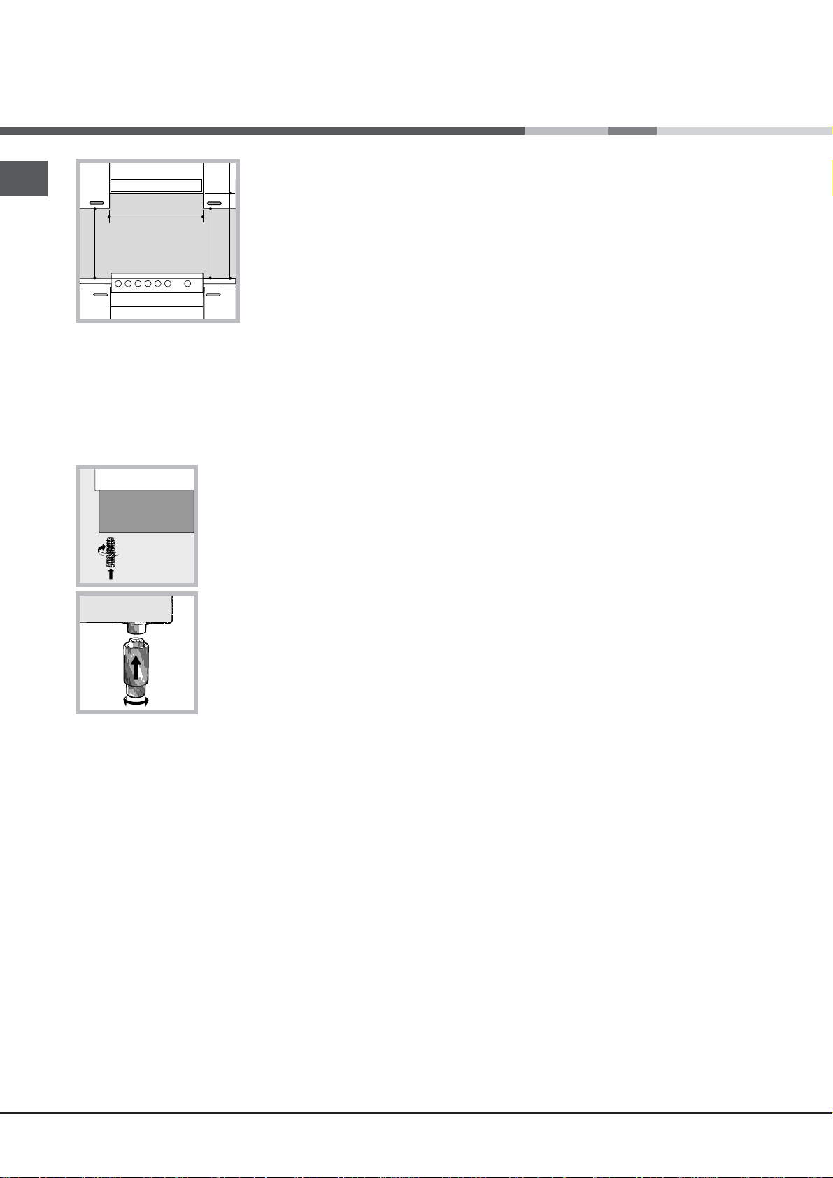
• If the top of the hob is higher than the cupboards,
the appliance must be installed at least 600 mm away
from them.
• If the cooker is installed underneath a wall cabinet,
there must be a minimum distance of 420 mm
between this cabinet and the top of the hob.
This distance should be increased to 700 mm if the
wall cabinets are flammable (see gure).
3
Page 4
GB
HOOD
420
Min.
min.
650
mm. with hood
min.
700
mm. without hood
mm.
600
Min. mm.
420
Min. mm.
• Do not position
blinds behind the cooker or less than 200 mm away
from its sides.
• Any hoods must be installed according to the
instructions listed in the relevant operating manual.
• The voltage is in the range between the values
indicated on the data plate.
• The socket is compatible with the plug of the
appliance. If the socket is incompatible with the
plug, ask an authorised technician to replace it. Do
not use extension cords or multiple sockets.
! Once the appliance has been installed, the power
supply cable and the electrical socket must be easily
accessible.
! The cable must not be bent or compressed.
! The cable must be checked regularly and replaced
by authorised technicians only.
Levelling
If it is necessary to level the
appliance, screw the adjustable
feet into the places provided on
each corner of the base of the
cooker (see gure).
The legs* fit into the slots on the
underside of the base of the
cooker.
Electrical connection
Install a standardised plug corresponding to the load
indicated on the appliance data plate (see Technical
data table).
The appliance must be directly connected to the mains
using an omnipolar circuit-breaker with a minimum contact
opening of 3 mm installed between the appliance and the
mains. The circuit-breaker must be suitable for the charge
indicated and must comply with current national legislation
(the earthing wire must not be interrupted by the circuitbreaker). The supply cable must be positioned so that it
does not come into contact with temperatures higher than
50°C at any point.
Before connecting the appliance to the power supply,
make sure that:
• The appliance is earthed and the plug is compliant with
the law.
• The socket can withstand the maximum power of the
appliance, which is indicated by the data plate.
* Only available in certain models
4
! The manufacturer declines any liability should
these safety measures not be observed.
Gas connection
Connection to the gas network or to the gas cylinder
may be carried out using a flexible rubber or steel hose,
in accordance with current national legislation and after
making sure that the appliance is suited to the type of gas
with which it will be supplied (see the rating sticker on
the cover: if this is not the case see below). When using
liquid gas from a cylinder, install a pressure regulator
which complies with current national regulations. To
make connection easier, the gas supply may be turned
sideways*: reverse the position of the hose holder with
that of the cap and replace the gasket that is supplied
with the appliance.
! Check that the pressure of the gas supply is
consistent with the values indicated in the Table
of burner and nozzle specifications (see below).
This will ensure the safe operation and durability of
your appliance while maintaining efficient energy
consumption.
Gas connection using a flexible rubber hose
Make sure that the hose complies with current national
legislation. The internal diameter of the hose must
measure: 8 mm for liquid gas supply; 13 mm for
methane gas supply.
Once the connection has been performed, make sure
that the hose:
• Does not come into contact with any parts that reach
temperatures of over 50°C.
• Is not subject to any pulling or twisting forces and
that it is not kinked or bent.
• Does not come into contact with blades, sharp
corners or moving parts and that it is not
compressed.
Page 5
• Is easy to inspect along its whole length so that its
V
condition may be checked.
• Is shorter than 1500 mm.
• Fits firmly into place at both ends, where it will
be fixed using clamps that comply with current
regulations.
! If one or more of these conditions is not fulfilled
or if the cooker must be installed according to the
conditions listed for class 2 - subclass 1 appliances
(installed between two cupboards), the flexible steel
hose must be used instead (see below).
Connecting a flexible jointless stainless steel pipe
to a threaded attachment
Make sure that the hose and gaskets comply with
current national legislation.
To begin using the hose, remove the hose holder on
the appliance (the gas supply inlet on the appliance is
a cylindrical threaded 1/2 gas male attachment).
! Perform the connection in such a way that the hose
length does not exceed a maximum of 2 metres,
making sure that the hose is not compressed and does
not come into contact with moving parts.
Adjusting the hob burners’ minimum setting:
1. Turn the tap to the minimum position.
2. Remove the knob and adjust the regulatory screw,
which is positioned inside or next to the tap pin, until
the flame is small but steady.
! If the appliance is connected to a liquid gas supply,
the regulatory screw must be fastened as tightly as
possible.
3. While the burner is alight, quickly change the position of
the knob from minimum to maximum and vice versa several
times, checking that the flame is not extinguished.
! The hob burners do not require primary air
adjustment.
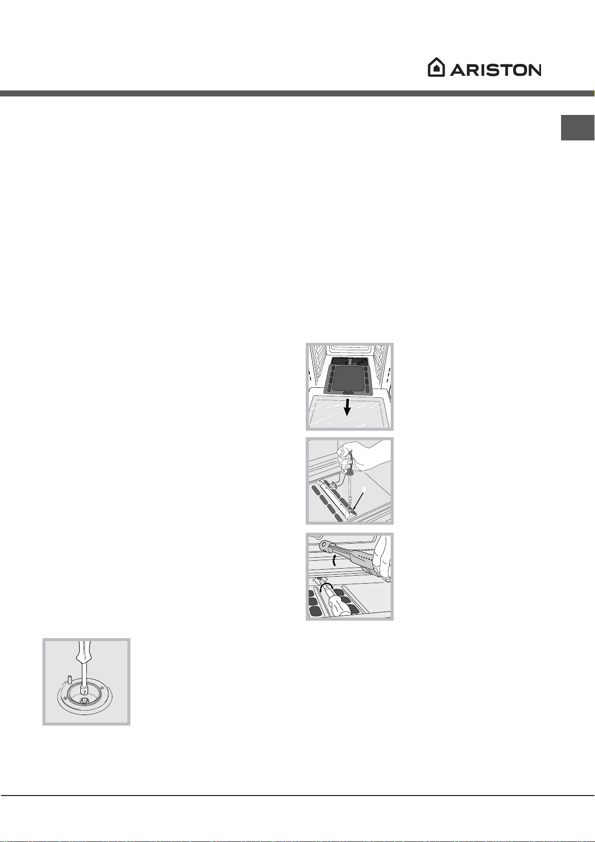
Adapting the oven
Replacing the oven burner nozzle:
1. Open the oven door fully
2. Pull out the sliding oven
bottom (see diagram).
GB
Checking the tightness of the connection
When the installation process is complete, check the
hose fittings for leaks using a soapy solution. Never
use a flame.
Adapting to different types of gas
It is possible to adapt the appliance to a type of gas
other than the default type (this is indicated on the
rating label on the cover).
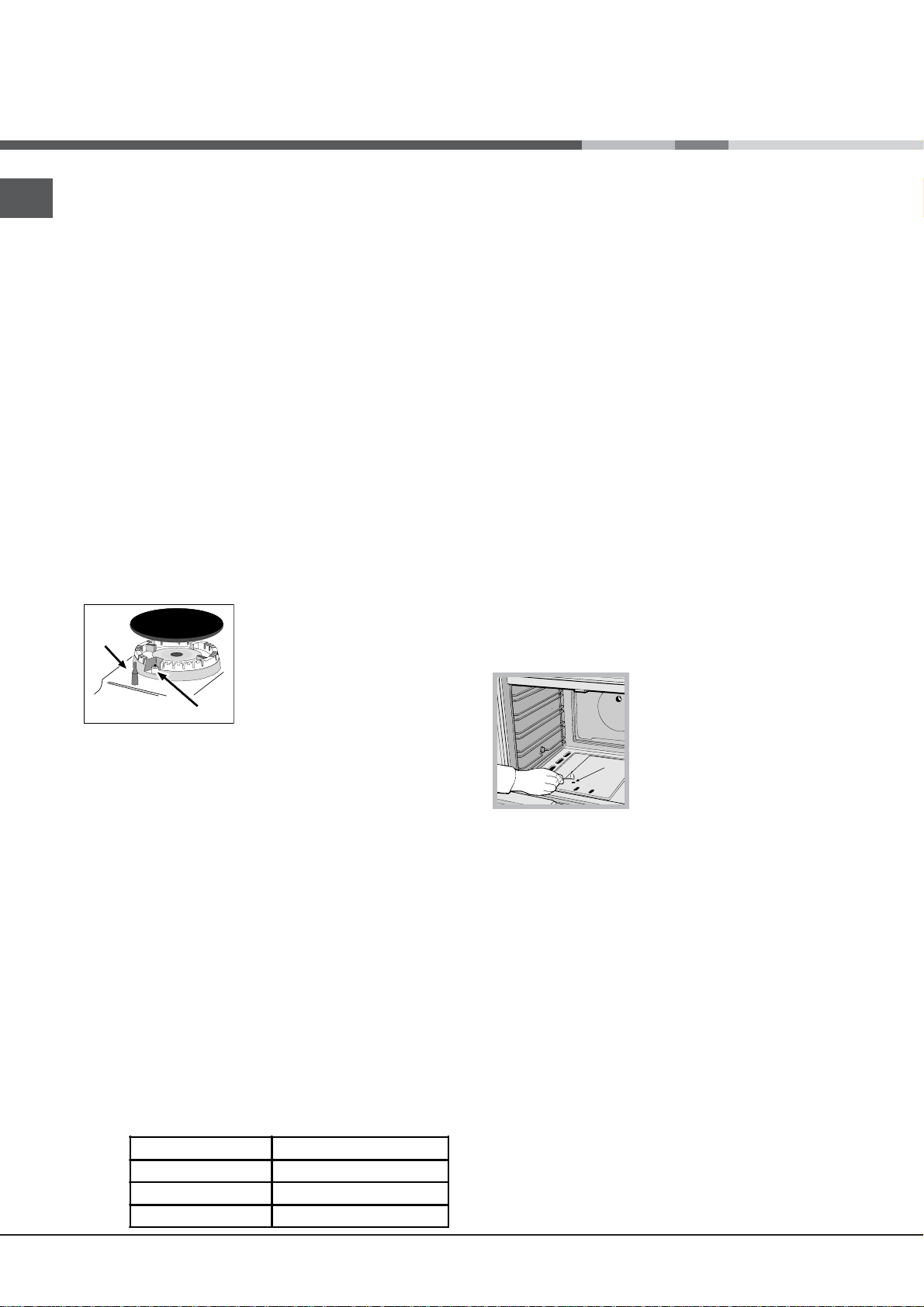
Adapting the hob
Replacing the nozzles for the hob burners:
1. Remove the hob grids and slide the burners off their
seats.
2. Unscrew the nozzles using
a 7 mm socket spanner (see
gure), and replace them with
nozzles suited to the new type
of gas (see Burner and nozzle
speci cations table).
3. Replace all the components
by following the above
instructions in reverse.
3. Remove the oven burner
after unscrewing the screws V
(see gure).
4. Unscrew the nozzle using a
special nozzle socket spanner
(see gure) or with a 7 mm
socket spanner, and replace it
with a new nozzle that is suited
to the new type of gas (see
Burner and nozzle speci cations
table).
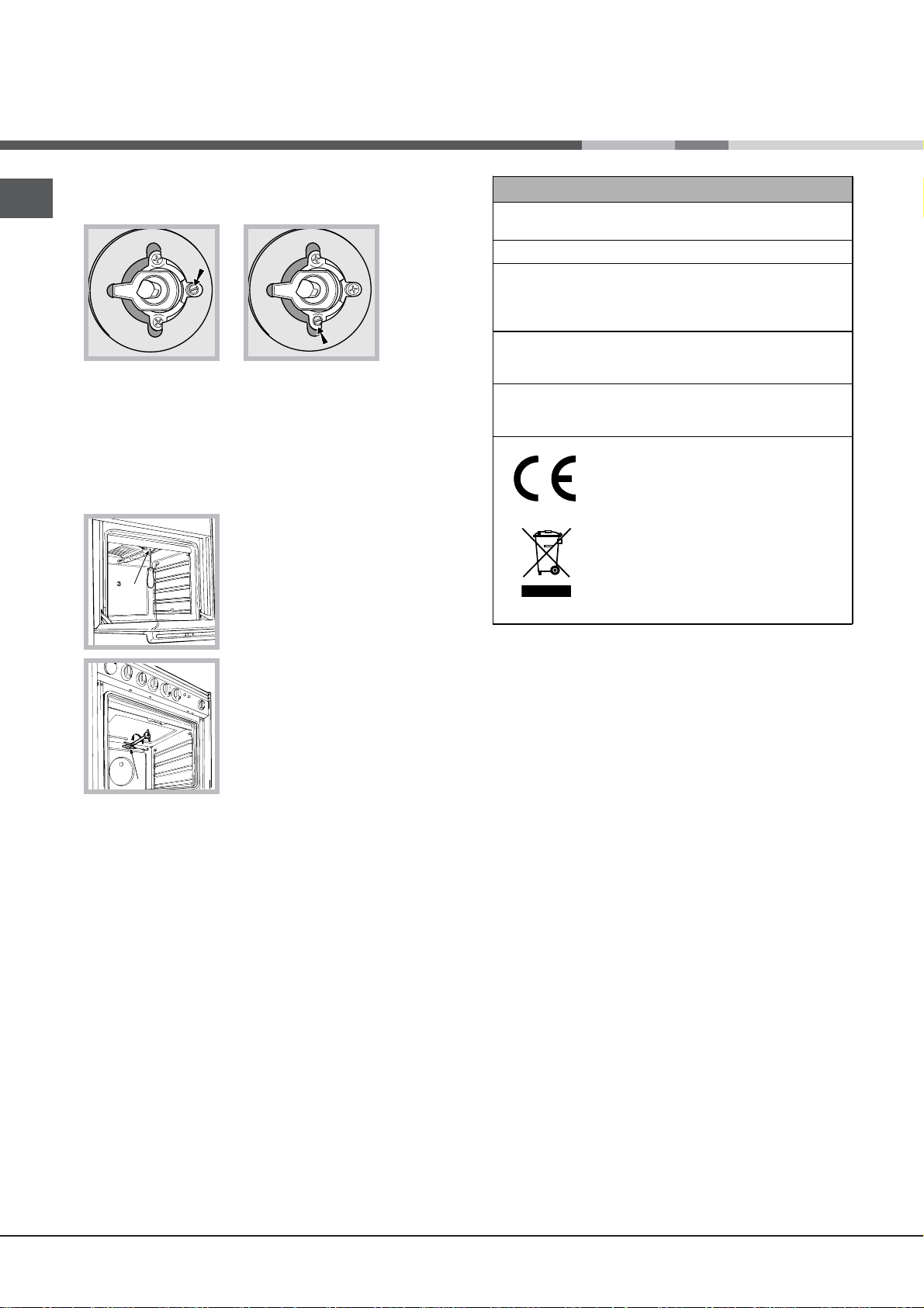
Adjusting the gas oven burner’s minimum setting:
1. Light the burner (see Start-up and Use).
2. Turn the knob to the minimum position (MIN)
after it has been in the maximum position (MAX) for
approximately 10 minutes.
3. Remove the knob.
4. Tighten or loosen the adjustment screws on the
outside of the thermostat pin (see gure) until the flame
is small but steady.
! In the case of natural gas, the adjustment screw must
be unscrewed by turning it anti-clockwise.
5
Page 6
GB
V
I
5. Turn
the
knob from the MAX position to the MIN position quickly
or open and shut the oven door, making sure that the
burner is not extinguished.
Adapting the grill
Replacing the grill burner nozzle:
1. Remove the oven burner
after loosening screw V (see
gure).
TECHNICAL DATA
Oven Dimensions
HxWxD
Volume
Useful
measurements
relating to the
oven compartment
Voltage and
frequency
Burners
31x43,5x43,5 cm
58 l
width 46 cm
depth 42 cm
height 8,5 cm
see data plate
may be adapted for use with any
type of gas shown on the data
plate.
EC Directives 2006/95/EC dated
12/12/06 (Low Voltage) and
subsequent amendments 04/108/EC dated 15/12/04
(Electromagnetic Compatibility)
and subsequent amendments -
2009/142/EC dated 30/11/09 (Gas)
and subsequent amendments 90/68/EEC dated 22/07/93 and
subsequent amendments. 2002/96/EC.
1275/2008(Stand-by/Off-mode)
2. Unscrew the grill burner
nozzle using a special nozzle
socket spanner (see gure) or
preferably with a 7 mm socket
spanner, and replace it with a
new nozzle that is suited to the
new type of gas (see Burner and
nozzle speci cations table).
! Be careful of the spark plug wires and the
thermocouple tubes.
! The oven and grill burners do not require primary air
adjustment.
! After adjusting the appliance so it may be used with
a different type of gas, replace the old rating label with
a new one that corresponds to the new type of gas
(these labels are available from Authorised Technical
Assistance Centres).
! Should the gas pressure used be different (or vary
slightly) from the recommended pressure, a suitable
pressure regulator must be fitted to the inlet hose in
accordance with current national regulations relating to
“regulators for channelled gas”.
6
Page 7
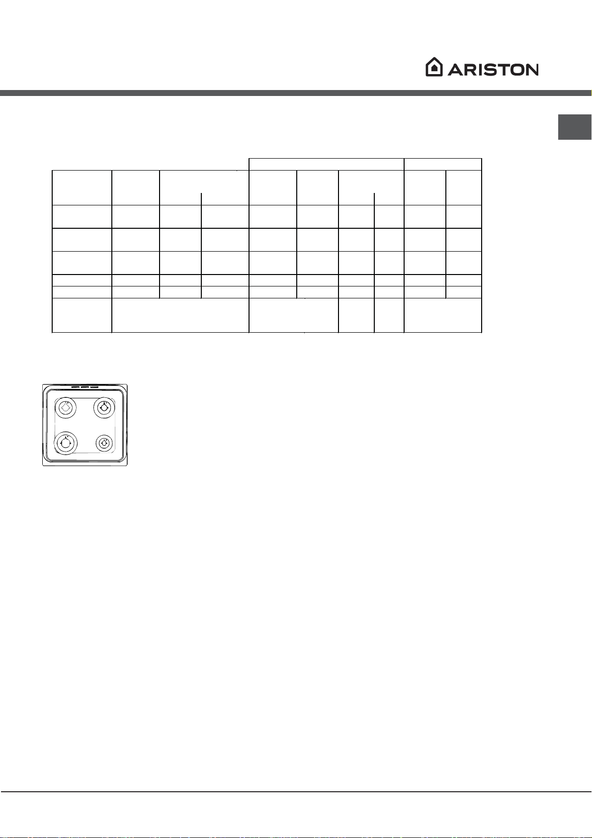
Table of burner and nozzle specifications
S
S
R
A
Table 1 Liquid Gas Natural Gas
Burner Diameter
(mm)
Nominal Reduced (mm) (mm) *** ** (mm)
Fast
(Large)(R)
Semi Fast
(Medium)(S)
Auxiliary
(Small)(A)
100 3.00 0.7 41 86 218 214 116 286
75 1.90 0.4 30 70 138 136 106 181
55 1.00 0.4 30 50 73 71 79 95
Oven - 2.60 1.0 52 78 189 186 119 189
Grill - 2.30 - - 75 167 164 114 219
Supply
Pressures
* At 15°C 1013 mbar-dry gas *** Butane P.C.S. = 49,47 MJ/Kg
** Propane P.C.S. = 50,37 MJ/Kg Natural P.C.S. = 37,78 MJ/m³
Thermal Power
kW (p.c.s.*)
Nominal (mbar)
Minimum (mbar)
Maximum (mbar)
By Pass
1/100
Nozzle
1/100
Flow*
28-30
20
35
g/h
37
25
45
Nozzle
1/100
Flow*
l/h
20
17
25
GB
CG64G1 F
CG64G1 X F
CG64G1 EX
CG640SG1 EX
7
Page 8
Start-up and use
F
X
D
GB
! Before operating the product, remove all plastic film
from the sides of the appliance.
Using the hob
Lighting the burners
For each BURNER knob there is a complete ring
showing the strength of the flame for the relevant
burner.
To light one of the burners on the hob:
1. Bring a flame or gas lighter close to the burner.
2. Press the BURNER knob and turn it in an
anticlockwise direction so that it is pointing to the
maximum flame setting .
3. Adjust the intensity of the flame to the desired level
by turning the BURNER knob in an anticlockwise
direction. This may be the minimum setting , the
maximum setting or any position in between the two.
If the appliance is fitted with an electronic lighting device*
(D ) press the BURNER knob
and turn it in an anticlockwise
direction, towards the
minimum flame setting, until
the burner is lit. The burner
may be extinguished when
the knob is released. If this
occurs, repeat the operation,
holding the knob down for a
longer period of time.
To identify the type of burner, please refer to the
diagrams contained in the “Burner and nozzle
specifications”.
! On the models supplied with a reducer shelf,
remember that this should be used only for the auxiliary
burner when you use casserole dishes with a diameter
under 12 cm.
Using the oven
! The first time you use your appliance, heat the empty
oven with its door closed at its maximum temperature
for at least half an hour. Ensure that the room is well
ventilated before switching the oven off and opening
the oven door. The appliance may emit a slightly
unpleasant odour caused by protective substances
used during the manufacturing process burning away.
! Never put objects directly on the bottom of the oven;
this will avoid the enamel coating being damaged.
Only use position 1 in the oven when cooking with the
rotisserie spit.
Lighting the oven
To light the oven burner, bring a flame or gas lighter
close to opening F (see gure)
and press the OVEN control
knob while turning it in an
anticlockwise direction until it
reaches the MAX position.
If the appliance is equipped with a flame failure safety
device*(X), press and hold the BURNER knob for
approximately 2-3 seconds to keep the flame alight
and to activate the device.
! If the flame is accidentally extinguished, switch off the
burner and wait for at least 1 minute before attempting
to relight it.
To switch the burner off, turn the knob until it reaches
the stop position
Practical advice on using the burners
For the burners to work in the most efficient way
possible and to save on the amount of gas consumed, it
is recommended that only pans that have a lid and a flat
base are used. They should also be suited to the size of
the burner.
Fast (R) 24 - 26
Semi Fast (S) 16 - 20
Auxiliary (A) 10 - 14
•.
Burner ř Cookware diameter (cm)
(see gure), press the OVEN knob and turn it in an
anticlockwise direction, towards the MAX position, until
the burner is lit. If, after 15 seconds, the burner is still
not alight, release the knob, open the oven door and
wait for at least 1 minute before trying to light it again.
If there is no electricity the burner may be lit using a
flame or a lighter, as described above.
! The oven is fitted with a safety device and it is
therefore necessary to hold the OVEN control knob
down for approximately 6 seconds.
! If the flame is accidentally extinguished, switch off the
burner and wait for at least 1 minute before attempting
to relight the oven.
* Only available in certain models.
If the appliance is fitted with
an electronic lighting device*
8
Page 9
Adjusting the temperature
D
Turnspit
GB
To set the desired cooking temperature, turn the
OVEN control knob in an anticlockwise direction.
Temperatures are displayed on the control panel and
may vary between MIN (150°C) and MAX (250°C).
Once the set temperature has been reached, the oven
will keep it constant by using its thermostat.
Grill
To light the grill, bring a flame or gas lighter close to
the burner and press the OVEN control knob while
turning it in a clockwise direction until it reaches the
position. If the appliance is fitted with an electronic
lighting device* (see gure), press the OVEN knob
and turn it in an clockwise direction, towards the
position, until the burner is lit. The grill enables
the surface of food to be browned evenly and is
particularly suitable for roast dishes, schnitzel and
sausages. Place the rack in position 4 or 5 and the
dripping pan in position 1 to collect fat and prevent the
formation of smoke.
! The grill is fitted with a safety device and it is
therefore necessary to hold the OVEN control knob
down for approximately 6 seconds.
! If the flame is accidentally extinguished, switch off the
burner and wait for at least 1 minute before attempting
to relight the grill.
To operate the rotisserie
(see diagram) proceed as
follows:
1. Place the dripping
pan in position 1.
2. Place the rotisserie
support in position 4 and
insert the spit in the hole
provided on the back
panel of the oven.
3. Acitvate the function by pressing the TURNSPIT
button.
Oven light
The light may be switched on at any moment by
pressing the OVEN LIGHT button.
Timer*
To activate the Timer proceed as follows:
1. Turn the TIMER knob in a clockwise direction for
almost one complete revolution to set the buzzer.
2. Turn the TIMER knob in an anticlockwise direction
to set the desired length of time.
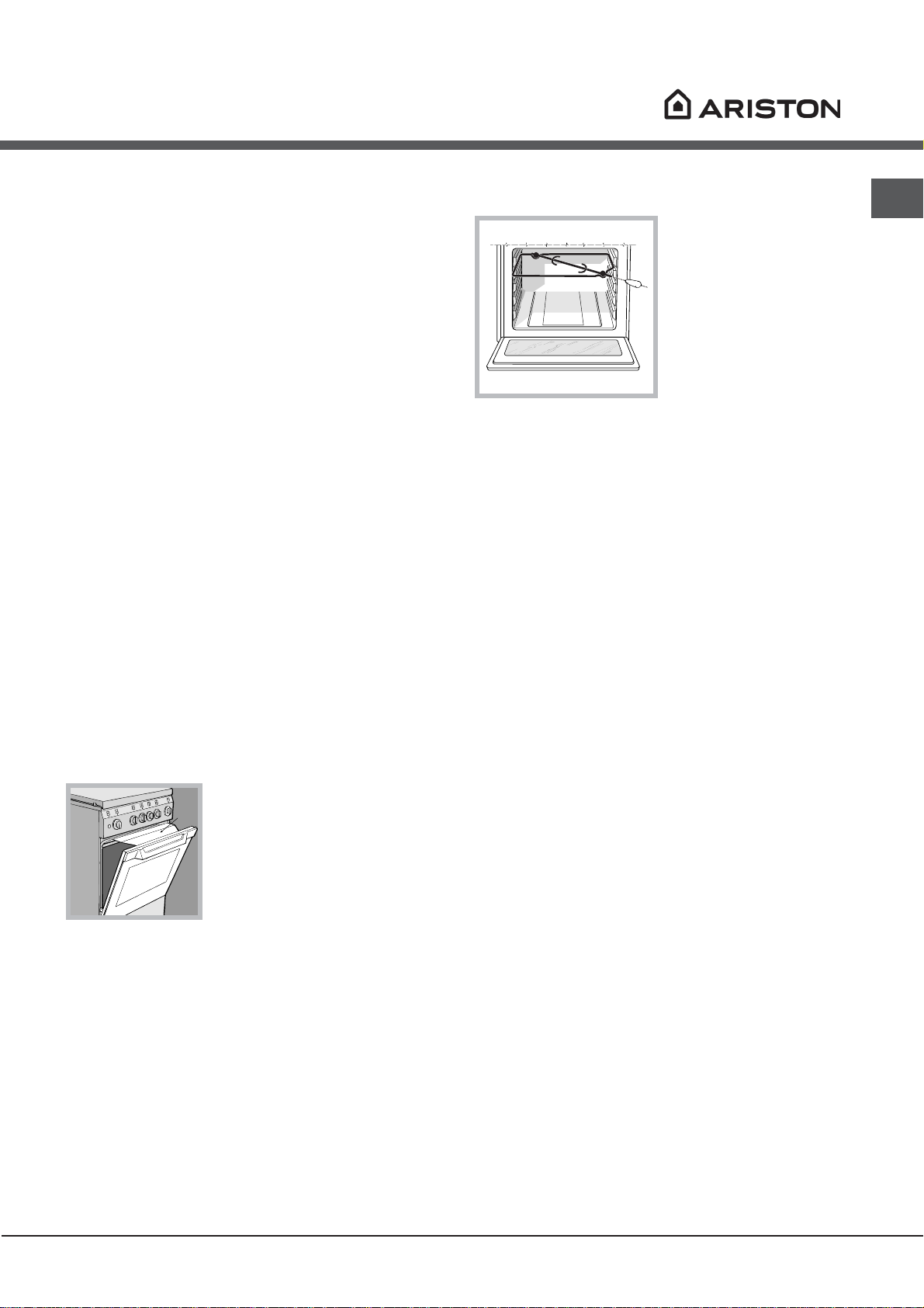
! When using the grill, leave
the oven door ajar, positioning
the deflector D between the
door and the control panel (see
gure) in order to prevent the
knobs from overheating.
* Only available in certain models.
9
Page 10
GB
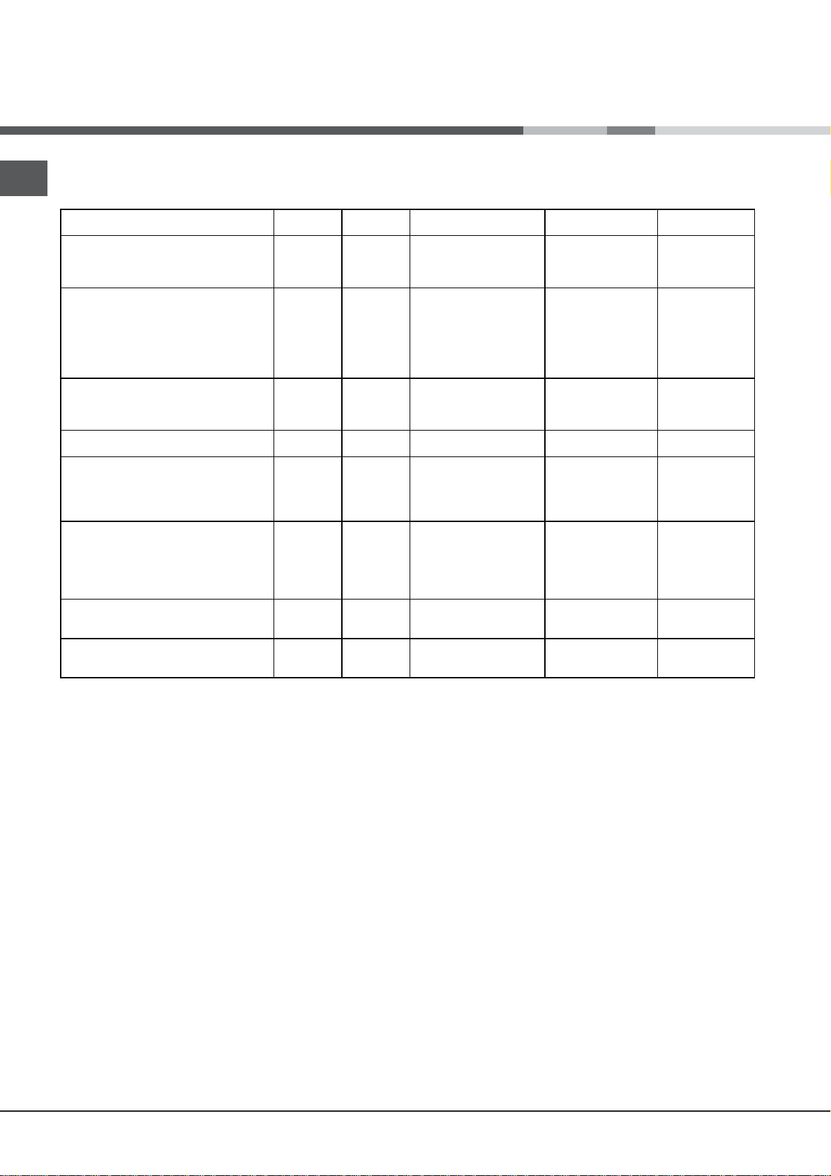
Oven cooking advice table
Foods
Pasta
Lasagne
Cannelloni
Gratin dishes
Meat
Veal
Chicken
Duck
Rabbit
Pork
Lamb
Fish
Mackerel
Dentex
Trout baked in foil
Pizza
Neapolitan-style
Pies
Biscuits
Tart
Savoury pies
Leavened cakes
Grilled foods
Veal steak
Cutlets
Hamburgers
Mackerel
Toast
Grilling using the rotisserie
Spit-roast veal
Spit-roast ch icken
Grilling using the multi-spit rotisserie*
Meat kebabs
Vegetable kebabs
Weight (in
kg)
2.5
2.5
2.5
1.7
1.5
1.8
2
2.1
1.8
1.1
1.5
1
1
0.5
1.1
1
1
1
1.5
1
1
4 pcs
1
2
1
0.8
Rack
position
3
3
3
3
3
3
3
3
3
3
3
3
3
3
3
3
3
4
4
3
4
4
-
-
-
-
Preheating time (min)
10
10
10
10
10
10
10
10
10
10
10
10
15
15
15
15
15
5
5
5
5
5
5
5
5
5
Recommended
Temperature (°C)
210
200
200
200
220
200
200
200
200
180-200
180-200
180-200
220
180
180
180
180
Cooking time
(minutes)
100-110
60-75
40-50
40-50
85-90
90-100
70-80
70-80
90-95
35-40
40-50
40-45
15-20
30-35
30-35
45-50
35-40
15-20
20
20-30
15-20
2-4
70-80
70-80
40-45
25-30
10
Page 11

Precautions and tips
! This appliance has been designed and manufactured
in compliance with international safety standards.
The following warnings are provided for safety reasons
and must be read carefully.
General safety
• The appliance was designed for domestic use inside
the home and is not intended for commercial or
industrial use.
• The appliance must not be installed outdoors, even in
covered areas. It is extremely dangerous to leave the
appliance exposed to rain and storms.
• Do not touch the appliance with bare feet or with wet
or damp hands and feet.
• The appliance must be used by adults only for
the preparation of food, in accordance with the
instructions outlined in this booklet. Any other
use of the appliance (e.g. for heating the room)
constitutes improper use and is dangerous.
The manufacturer may not be held liable for any
damage resulting from improper, incorrect and
unreasonable use of the appliance.
• The instruction booklet accompanies a class 1
(insulated) or class 2 - subclass 1 (recessed
between 2 cupboards) appliance.
• When the appliance is in use, the heating
elements and some parts of the oven door
become extremely hot. Make sure you don’t
touch them and keep children well away.
• Make sure that the power supply cables of other
electrical appliances do not come into contact with
the hot parts of the oven.
• The openings used for the ventilation and dispersion
of heat must never be covered.
• Do not close the glass hob cover (selected models
only) when the burners are alight or when they are
still hot.
• Always use oven gloves when placing cookware in
the oven or when removing it.
• Do not use flammable liquids (alcohol, petrol, etc...)
near the appliance while it is in use.
• Do not place flammable material in the lower storage
compartment or in the oven itself. If the appliance is
switched on accidentally, it could catch fire.
• The internal surfaces of the compartment (where
present) may become hot.
• Always make sure the knobs are in the
and that the gas tap is closed when the appliance is
not in use.
• When unplugging the appliance, always pull the plug
from the mains socket; do not pull on the cable.
• Never perform any cleaning or maintenance work
without having disconnected the appliance from the
electricity mains.
• position
• If the appliance breaks down, under no
circumstances should you attempt to repair
the appliance yourself. Repairs carried out by
inexperienced persons may cause injury or further
malfunctioning of the appliance. Contact Assistance.
• Do not rest heavy objects on the open oven door.
• The appliance should not be operated by people
(including children) with reduced physical, sensory
or mental capacities, by inexperienced individuals
or by anyone who is not familiar with the product.
These individuals should, at the very least, be
supervised by someone who assumes responsibility
for their safety or receive preliminary instructions
relating to the operation of the appliance.
• Do not let children play with the appliance.
Disposal
• When disposing of packaging material: observe local
legislation so that the packaging may be reused.
• The European Directive 2002/96/EC on Waste
Electrical and Electronic Equipment (WEEE),
requires that old household electrical appliances
must not be disposed of in the normal unsorted
municipal waste stream. Old appliances must
be collected separately in order to optimise the
recovery and recycling of the materials they contain
and reduce the impact on human health and the
environment. The crossed out “wheeled bin” symbol
on the product reminds you of your obligation,
that when you dispose of the appliance it must be
separately collected.
Consumers should contact their local authority
or retailer for information concerning the correct
disposal of their old appliance.
Respecting and conserving the
environment
• You can help to reduce the peak load of the
electricity supply network companies by using the
oven in the hours between late afternoon and the
early hours of the morning.
• Check the door seals regularly and wipe them clean
to ensure they are free of debris so that they adhere
properly to the door, thus avoiding heat dispersion.
GB
11
Page 12

Care and maintenance
GB
Switching the appliance off
Disconnect your appliance from the electricity supply
before carrying out any work on it.
Cleaning the appliance
! Never use steam cleaners or pressure cleaners on
the appliance.
• The stainless steel or enamel-coated external parts
and the rubber seals may be cleaned using a
sponge that has been soaked in lukewarm water
and neutral soap. Use specialised products for the
removal of stubborn stains. After cleaning, rinse well
and dry thoroughly. Do not use abrasive powders or
corrosive substances.
• The hob grids, burner caps, flame spreader rings
and burners may be removed to make cleaning
easier; wash them in hot water and non-abrasive
detergent, making sure all burnt-on residue is
removed before drying them thoroughly.
• Clean the terminal part of the flame failure safety
devices* frequently.
• The inside of the oven should ideally be cleaned
after each use, while it is still lukewarm. Use hot
water and detergent, then rinse well and dry with a
soft cloth. Do not use abrasive products.
Clean the glass part of the oven door using a
•
sponge and a non-abrasive cleaning product, then
dry thoroughly with a soft cloth. Do not use rough
abrasive material or sharp metal scrapers as these
could scratch the surface and cause the glass to
crack.
• The accessories can be washed like everyday
crockery, and are even dishwasher safe.
• Do not close the cover when the burners are alight
or when they are still hot.
Replacing the oven light bulb
1. After disconnecting the
oven from the electricity mains,
remove the glass lid covering
the lamp socket (see gure).
2. Remove the light bulb and
replace it with a similar one:
voltage 230 V, wattage 25 W,
cap E 14.
3. Replace the lid and reconnect the oven to the
electricity supply.
Gas tap maintenance
Over time, the taps may become jammed or difficult to
turn. If this happens, the tap must be replaced.
! This procedure must be performed by a qualified
technician authorised by the manufacturer.
The catalytic self-cleaning system*
Some models have oven liners coated with a porous
enamel also known as catalytic enamel.
When hot, this enamel destroys all greasy food
particles. For this „oxidation” to occur, the oven liners
must reach a temperature of at least 170°C.
When cooking is done, should some grease and food
particles remain on the oven liners, leave the appliance
on with nothing in it and the door shut, with the OVEN
knob on the maximum setting, for 60-90 minutes,
depending on the degree of soil. You can remove
large amounts of grease using hot water and a soft
brush.
! Catalytic enamel is very strong, but nonetheless,
avoid:
scratching the enamel with sharp objects (i.e. a knife),
and using abrasive detergents or products to clean it,
otherwise you will destroy the enamel’s self-cleaning
properties.
Assistance
Inspecting the oven seals
Check the door seals around the oven regularly. If
the seals are damaged, please contact your nearest
Authorised After-sales Service Centre. We recommend
that the oven is not used until the seals have been
replaced.
* Only available in certain models.
12
! Never use the services of an unauthorised technician.
Please have the following information to hand:
• The type of problem encountered.
• The appliance model (Mod.).
• The serial number (S/N).
The latter two pieces of information can be found on
the data plate located on the appliance.
Page 13

Installation
! Conservez ce mode d’emploi pour pouvoir le
consulter à tout moment. En cas de vente, de
cession ou de déménagement, veillez à ce qu’il suive
l’appareil.
! Lisez attentivement les instructions : elles contiennent
des conseils importants sur l’installation, l’utilisation et
la sécurité de votre appareil.
! L’installation de l’appareil doit être effectuée par
un professionnel du secteur conformément aux
instructions du fabricant.
! N’importe quelle opération de réglage, d’entretien,
etc., doit être effectuée après avoir débranché la prise
de la cuisinière.
Conditions réglementaires d’installation
Le raccordement gaz devra être fait par un
professionnel qualifié qui assurera la bonne
alimentation en gaz et le meilleur réglage de la
combustion des brûleurs. Ces opérations d’installation,
quoique simples, sont délicates et
primordiales pour que votre cuisinière vous rende
le meilleur service. L’installation doit être effectuée
conformément aux textes réglementaires et règles de
l’art en vigueur, notamment:
• Arrêté du 2 août 1977. Règles techniques et de
sécurité applicables aux installations de gaz
combustibles et d’hydro-carbures liquéfiés situées
à l’intérieur des bâtiments d’habitation et de leur
dépendances.
• Norme DTU P45-204. Installations de gaz
(anciennement DTU n° 61-1-installations de gaz Avril 1982 + additif n°1 Juillet 1984).
• Règlement sanitaire départemental.
pièces voisines (voir figure B) – à condition qu’il ne
s’agisse pas de parties communes du bâtiment, de
chambres à coucher ou de locaux à risque d’incendie
– équipées d’un conduit d’aération avec l’extérieur
comme décrit plus haut.
Local adjacent
A B
A
Ouverture de ventilation
pour l’air comburant
! Après une utilisation prolongée de l’appareil, il est
conseillé d’ouvrir une fenêtre ou d’augmenter la vitesse
de ventilateurs éventuels.
Evacuation des fumées de combustion
La pièce doit prévoir un système d’évacuation vers
l’extérieur des fumées de combustion réalisé au moyen
d’une hotte reliée à une cheminée à tirage naturel ou
par ventilateur électrique qui entre automatiquement
en fonction dès qu’on allume l’appareil (voir figures).
Local à ventiler
Agrandissement de la
fissure entre la porte et
le sol
FR
Aération des locaux
L’appareil doit être installé dans des locaux qui sont
aérés en permanence, selon les prescriptions des
Normes en vigueur dans le pays d’installation. Il est
indispensable que la pièce où l’appareil est installé
dispose d’une quantité d’air égale à la quantité d’air
comburant nécessaire à une bonne combustion du
gaz (le flux d’air doit être d’au moins 3 m
puissance installée).
Les prises d’air, protégées par des grilles, doivent
disposer d’un conduit d’au moins 2 cm2 de section
utile et dans une position qui leur évite tout risque
d’être bouchées accidentellement, même partiellement
(voir figure A).
Ces ouvertures doivent être agrandies de 100%
(surface minimale 2 cm2) en cas d’appareils
dépourvus du dispositif de sécurité de flamme et
quand l’afflux de l’air provient de manière indirecte de
3
/h par kW de
Evacuation
directement à
l’extérieur
! Les gaz de pétrole liquéfiés, plus lourds que l’air,
se déposent et stagnent dans le bas. Les locaux
qui contiennent des bouteilles de G.P.L doivent
donc prévoir des ouvertures vers l’extérieur afin de
permettre l’évacuation du gaz par le bas en cas de
fuites accidentelles. Ne pas installer ou entreposer de
bouteilles de GPL, vides ou partiellement pleines, dans
des locaux qui se trouvent en sous-sol (caves etc.). Ne
gardez dans la pièce que la bouteille que vous êtes en
train d’utiliser, loin de sources de chaleur (fours, feux de
bois, poêles etc.) qui pourraient amener sa température
à plus de 50°C.
Evacuation par cheminée ou
conduit de fumée ramifié (réservé
aux appareils de cuisson)
13
Page 14

FR
HOOD
420
Min.
min.
650
mm. with hood
min.
700
mm. without hood
mm.
600
Min. mm.
420
Min. mm.
Positionnement et nivellement
! L’appareil peut être installé à côté de meubles dont la
hauteur ne dépasse pas celle du plan de cuisson.
! Assurez-vous que le mur en contact avec la paroi
arrière de l’appareil est réalisée en matériel ignifuge
résistant à la chaleur (T 90°C).
Pour une installation correcte :
• installez cet appareil dans une cuisine, une salle
à manger ou un studio (jamais dans une salle de
bains);
• si le plan de cuisson de la cuisinière dépasse le
plan de travail des meubles, ces derniers doivent
être placés à au moins 200 mm de l’appareil;
• si la cuisinière est
installée sous un
élément suspendu,
il faut que ce dernier
soit placé à au moins
420mm de distance du
plan. Il faut prévoir une
distance de 700mm si les
éléments suspendus sont
inflammables (voir gure);
• ne placez pas de
rideaux derrière la cuisinière ou sur ses côtés à
moins de 200 mm de distance;
• pour l’installation de hottes, conformez-vous aux
instructions de leur notice d’emploi.
Nivellement
Pour mettre l’appareil bien
à plat, vissez les pieds
de réglage fournis aux
emplacements prévus aux
coins à la base de la cuisinière
(voir figure).
Montage des pieds* par
encastrement sous la base.
intercaler entre l’appareil et le réseau un interrupteur
à coupure omnipolaire ayant au moins 3 mm
d’écartement entre les contacts, dimensionné à la
charge et conforme aux normes en vigueur (le fil de
terre ne doit pas être interrompu par l’interrupteur). Le
câble d’alimentation ne doit atteindre, en aucun point,
des températures dépassant de 50°C la température
ambiante.
Avant de procéder au branchement, assurez-vous que :
• la prise est bien munie d’une terre conforme à la loi;
• la prise est bien apte à supporter la puissance
maximale de l’appareil, indiquée sur la plaquette
signalétique;
• la tension d’alimentation est bien comprise entre les
valeurs indiquées sur la plaquette signalétique;
• la prise est bien compatible avec la fiche de
l’appareil. Si ce n’est pas le cas, remplacez la prise
ou la fiche, n’utilisez ni rallonges ni prises multiples.
! Après installation de l’appareil, le câble électrique et
la prise de courant doivent être facilement accessibles
! Le câble ne doit être ni plié ni excessivement écrasé.
! Le câble doit être contrôlé périodiquement et ne peut
être remplacé que par un technicien agréé.
! Nous déclinons toute responsabilité en cas de non
respect des normes énumérées ci-dessus.
Raccordement gaz
Pour raccorder l’appareil au réseau de distribution
du gaz ou à la bouteille de gaz utilisez un tuyau
flexible en caoutchouc ou en acier, conformément
à la réglementation en vigueur. Assurez-vous
auparavant que l’appareil est bien réglé pour le
type de gaz d’alimentation utilisé (voir étiquette sur le
couvercle : autrement voir ci-dessous). Si l’alimentation
s’effectue avec du gaz liquide en bouteille, utilisez
des régulateurs de pression conformes à la
réglementation en vigueur dans le pays. Pour simplifier
le raccordement, l’alimentation du gaz est orientable
latéralement* : inversez l’about annelé avec le bouchon
de fermeture et remplacez le joint d’étanchéité (fourni
avec l’appareil).
Raccordement électrique
Montez sur le câble une prise normalisée pour la
charge indiquée sur l’étiquette des caractéristiques
(voir tableau des caractéristiques techniques).
En cas de raccordement direct au réseau, il faut
14
! Pour un fonctionnement en toute sécurité, pour
un meilleur emploi de l’énergie et une plus longue
durée de vie de l’appareil, vérifiez que la pression
d’alimentation respecte bien les valeurs indiquées
dans le tableau Caractéristiques des brûleurs et des
injecteurs (voir ci-dessous).
*N’existe que sur certains modèles
Page 15

Raccordement gaz par tuyau flexible en caoutchouc
V
Adaptation du plan de cuisson
FR
Assurez-vous que le tuyau est bien conforme aux
normes applicables dans le pays d’installation. Le
tuyau doit avoir un diamètre intérieur de : 8 mm en
cas d’alimentation au gaz liquide; 15 mm en cas
d’alimentation au gaz naturel.
Après avoir effectué le raccordement, assurez-vous
que le tuyau :
• ne touche en aucun point à des parties pouvant
atteindre plus de 50°C;
• ne soit pas soumis à traction ou torsion et ne
présente pas de pliures ou étranglements;
• ne risque pas d’entrer en contact avec des corps
tranchants, des arêtes vives, des parties mobiles et
ne soit pas écrasé;
• puisse être facilement contrôlable sur toute sa
longueur pour vérifier son état de conservation;
• ait moins de 1500mm de long;
• soit bien fixé à ses deux extrémités à l’aide de
bagues de serrage conformes à la réglementation
en vigueur dans le pays.
! Si une ou plusieurs de ces conditions ne peuvent
être remplies ou que la cuisinière est installée dans
des conditions de classe 2 – sous-classe 1 (appareil
encastré entre deux meubles), il faut utiliser un tuyau
flexible en acier (voir ci-dessous).
Raccordement gaz par tuyau flexible en acier inox,
à paroi continue avec raccords filetés
Assurez-vous que le tuyau et les joints sont bien
conformes aux normes applicables dans le pays
d’installation.
Pour installer le tuyau, enlevez l’about annelé équipant
l’appareil (le raccord d’entrée du gaz à l’appareil est
fileté 1/2 gaz mâle cylindrique).
Remplacement des injecteurs des brûleurs du plan de
cuisson:
1. enlevez les grilles du plan de cuisson et sortez les
brûleurs de leur logement;
2. dévissez les injecteurs à
l’aide d’une clé à tube de 7mm
(voir figure), et remplacez-les
par les injecteurs adaptés au
nouveau type de gaz (voir
tableau Caractéristiques des
brûleurs et des injecteurs) ;
3. remontez les différentes parties en effectuant les
opérations dans le sens inverse.
Réglage des minima des brûleurs du plan de
cuisson :
1. placez le robinet sur la position minimum;
2. enlevez le bouton et tournez la vis de réglage
positionnée à l’intérieur ou sur le côté de la tige du
robinet jusqu’à obtenir une petite flamme régulière;
! En cas de gaz naturel, il faut dévisser la vis de
réglage en tournant dans le sens inverse des aiguilles
d’une montre;
3. vérifiez si, en tournant rapidement le robinet du
maximum au minimum, le brûleur ne s’éteint pas.
! Les brûleurs du plan de cuisson ne nécessitent pas
de réglage de l’air primaire.
Adaptation du four
Remplacement du brûleur du four:
1. ouvrez complètement la porte du four;
2. enlever la protection
coulissante
(voir gure);
! Procédez au raccordement de manière à ce que
la longueur du tuyau ne dépasse pas 2 mètres
d’extension maximale. Veillez à ce que le tuyau ne soit
pas écrasé et ne touche en aucun point à des parties
mobiles.
Vérification de l’étanchéité
Une fois l’installation terminée, vérifiez l’étanchéité de
tous les raccords en utilisant une solution savonneuse,
n’utilisez jamais de flamme.
Adaptation aux différents types de gaz
L’appareil peut être adapté à un type de gaz autre que
celui pour le quel il a été conçu (indiqué sur l’étiquette
de réglage sur le couvercle).
3. déposer le brûleur du four
après avoir enlevé la vis V (voir
gure);
15
Page 16

FR
V
I
4. dévisser l’injecteur du brûleur
à l’aide de la clé à tube spéciale
pour injecteurs (voir gure) ou
d’une clé à tube de 7 mm et
le remplacer par l’injecteur
adapté au nouveau type de gaz
(voir tableau Caractéristiques des
brûleurs et des injecteurs).
Réglage du minimum du brûleur du four à gaz :
1. allumer le brûleur (voir Mise en marche et Utilisation);
2. amener la manette sur la position minimum (MIN)
après l’avoir laissée pendant environ 10 minutes sur la
position maximum (MAX);
3. enlever le bouton;
4. agir sur la vis de réglage positionnée à l’extérieur de
la tige du thermostat (voir gure) jusqu’à obtenir une
petite flamme régulière.
! En cas de gaz naturel, il faut dévisser la vis de
réglage en tournant dans le sens inverse des aiguilles
d’une montre;
2. dévisser l’injecteur du brûleur
du gril à l’aide de la clé à tube
adaptée pour les injecteurs
(voir Figure), ou mieux encore
avec une clé à tube de 7 mm.
et le remplacer par celui adapté
au nouveau type de gaz (voir
tableau Caractéristiques brûleurs
et injecteurs).
! Les brûleurs du four et du gril ne nécessitent pas de
réglage de l’air primaire.
! Faire très attention aux câbles des bougies et aux
tuyaux des thermocouples.
! Après avoir procédé au réglage pour le nouveau
type de gaz, remplacer la vieille étiquette par celle
correspondant au nouveau gaz, disponible dans les
centres d’assistance technique agréés.
! Si la pression du gaz diffère (ou varie) par rapport
à la pression prévue, il faut installer, sur la tuyauterie
d’entrée un régulateur de pression approprié conforme
à la réglementation sur les “régulateurs pour gaz
canalisés” en vigueur dans le pays.
5.
vérifier si, en tournant rapidement le bouton de la
position MAX à la position MIN, ou en ouvrant et
fermant rapidement la porte du four, le brûleur ne
s’éteint pas.
Adaptation du gril
Remplacement de l’injecteur du brûleur du gril :
1. déposer le brûleur du gril
après avoir enlevé la vis V (voir
gure);
CARACTERISTIQUES TECHNIQUES
Dimensions du
Four HxLxP
Volume
Dimensions utiles
du tiroir chauffeplats
Tension et
fréquence
d’alimentation :
Brûleurs
31x43,5x43,5 cm
58 l
largeur 46 cm
profondeur 42 cm
hauteur 8,5 cm
voir plaquette signalétique
adaptables à n'importe quel type de
gaz parmi ceux indiqués sur le
plaquette signalétique
Directives Communautaires
2006/95/EC du 12/12/06 (Basse
Tension) et modifications suivantes
- 2004/108/EC du 15/12/04
(Compatibilité Electromagnétique)
et modifications suivantes 90/369/EEC du 29/06/90 (Gaz) et
modifications suivantes 93/68/EEC du 22/07/93 et
modifications suivantes 2002/96/EC
1275/2008(Stand-by/Off-mode)
16
Page 17

Tableau Caractéristiques des brûleurs et des injecteurs
S
S
R
A
Tableau 1 Ga z li quide Ga z na turel
FR
Brűleur Dia mčtre
(mm)
Puissance
the rmique
Bipasse
1/100
injecteur
1/100
débit*
g/h
injecteur
1/100
débit*
l/h
kW (p.c.s.*)
N omin. Réduit . (mm) (mm) * ** ** (mm) G2 0 G25
Rapide
(Grand)(R)
Semi Rapide
(Moyen)(S)
Auxilia ire
(Petit)(A)
100 3.00 0.70 41 86 218 214 116 286 332
75 1.90 0.40 30 70 138 136 106 181 210
55 1.00 0.40 30 50 73 71 79 95 111
Four — 2.60 1.00 52 78 182 179 119 238 277
Gril — 2.30 — — 75 167 164 114 219 255
Pressions
d' alime nta tio n
* A 15°C et 1013 mbar-gaz sec
** Propane P.C.S. = 50,37 MJ/Kg
*** Butane P.C.S. = 49,47 MJ/Kg
Naturel G20 P.C.S = 37,78 MJ/m
Naturel G25 P.C.S = 32,49 MJ/m
Nominale (mbar)
Minimum ( mb ar)
Maximum (mbar)
3
3
28-30
20
35
37
25
45
20
17
25
25
20
30
CG64G1 F
CG64G1 X F
CG64G1 EX
CG640SG1 EX
Tension et fréquence d'alimentation de la partie électrique et
caractéristiques de la partie gaz
Modčle Partie gaz Partie électrique
Classe Puissance nominale
Tension
kW (1)
CG64G1 EX
II2E+3+
10,40 (756 g/h-G30)
(743 g/h - G31)
220-240V~
50-60Hz
(1) Les valeurs exprimées en g/h se réfčrent aux capacités pour
les gaz liquides (butane, propane).
17
Page 18

Mise en marche et utilisation
F
X
D
FR
! Avant toute utilisation, vous devez impérativement
enlever les films plastiques situés sur les côtés de
l’appareil
Utilisation du plan de cuisson
Allumage des brûleurs
Un petit cercle plein près de chaque manette
BRULEUR indique le brûleur associé à ce dernier.
Pour allumer un brûleur du plan de cuisson :
1. approchez une flamme ou un allume-gaz ;
2. poussez sur le manette du BRULEUR tout en le
tournant dans le sens inverse des aiguilles d’une
montre jusqu’au symbole grande flamme .
3. pour régler la puissance de la flamme souhaitée,
tournez le manette BRULEUR dans le sens inverse
des aiguilles d’une montre : sur la position minimum
, sur la position maximum ou sur une position
intermédiaire.
Si l’appareil est équipé d’un
allumage électronique* (D)
il suffit de pousser et de
tourner en même temps
dans le sens inverse des
aiguilles d’une montre le
manette BRULEUR sur le
symbole petite flamme,
jusqu’à l’allumage. Il peut
arriver que le brûleur
s’éteigne dès que vous lâchez le bouton. Dans ce cas,
essayez à nouveau en poussant plus longtemps sur le
manette.
Si l’appareil est équipé d’un dispositif de sécurité*X de
flamme, poussez sur le manette BRULEUR pendant
2-3 secondes pour garder la flamme allumée et pour
activer le dispositif.
! En cas d’extinction accidentelle des flammes,
éteignez le brûleur et attendez au moins 1 minute avant
de tenter de rallumer.
Pour éteindre le brûleur, tournez le bouton jusqu’à la
position d’arrêt
Brűleur ř Diamčtre récipients (cm)
Rapide (R) 24 – 26
.
Conseils pratiques pour l’utilisation des brûleurs
Pour un meilleur rendement des brûleurs et une
moindre consommation de gaz, utilisez des casseroles
à fond plat, munies de couvercle et d’un diamètre
adapté au brûleur :
Pour distinguer le type de brûleur reportez-vous aux
dessins figurant dans le paragraphe „Caractéristiques
des brûleurs et des injecteurs”
! Pour les modèles équipés d’une grille de réduction,
n’utilisez cette dernière que pour le brûleur auxiliaire
quand vous utilisez des casseroles ayant moins de 12
cm de diamètre.
Utilisation du four
! Lors de son premier allumage, faites fonctionner
le four à vide, porte fermée, pendant au moins une
heure en réglant la température à son maximum. Puis
éteignez-le, ouvrez la porte et aérez la pièce. L’odeur
qui se dégage est due à l’évaporation des produits
utilisés pour protéger le four.
! Ne posez jamais d’objets
à même la sole du four,
vous pourriez abîmer l’émail.
N’utilisez la position 1 du four
qu’en cas de cuissons au
tournebroche.
Allumage du four
Pour allumer le brûleur du four, approchez une flamme
ou un allume-gaz de l’orifice F (voir figure), poussez
sur le bouton FOUR et tournez-le en même temps dans
le sens inverse des aiguilles d’une montre jusqu’à la
position MAX.
Si l’appareil est équipé d’un allumage électronique*
il suffit de pousser sur le bouton FOUR et de le
tourner en même temps dans le sens inverse des
aiguilles d’une montre jusqu’à la position MAX, jusqu’à
l’allumage. Si au bout de 15 secondes le brûleur ne
s’est toujours pas allumé, lâchez le bouton, ouvrez
la porte du four et attendez au moins 1 minute avant
de tenter un nouvel allumage. En cas de panne de
courant, vous pouvez allumer le brûleur avec une
flamme ou avec un allume-gaz comme décrit plus
haut.
Semi-Rapide (S) 16 – 20
Auxiliaire (A) 10 – 14
*N’existe que sur certains modèles
18
Page 19

D
! Le four étant équipé d’un dispositif de sécurité de
flamme, il faut pousser sur le bouton du FOUR pendant
environ 6 secondes.
! En cas d’extinction accidentelle de flamme, éteignez
le brûleur et attendez au moins 1 minute avant de
tenter de rallumer.
Pour éteindre le brûleur, tourner le bouton jusqu’à la
position d’arrêt
Réglage de la température
Pour sélectionner la température de cuisson souhaitée,
tournez le bouton FOUR dans le sens inverse des
aiguilles d’une montre. Les températures sont
indiquées sur le tableau de bord et vont d’un MIN
(140°C) à un MAX (250°C). Une fois que la température
est atteinte dans le four, un thermostat la maintient
constante au degré prêt.
Gril
Tournez le bouton FOUR dans le sens inverse des
aiguilles d’une montre jusqu’à la position pour
brancher le gril à rayons infrarouges.
Si l’appareil est équipé d’un allumage électronique* il
suffit de pousser sur le bouton FOUR et de le tourner
en même temps dans le sens des aiguilles d’une
montre jusqu’à la position , jusqu’à l’allumage. Si au
bout de 15 secondes le brûleur ne s’est toujours pas
allumé, lâchez le bouton, ouvrez la porte du four et
attendez au moins 1 minute avant de tenter un nouvel
allumage. En cas de panne de courant, vous pouvez
allumer le brûleur avec une flamme ou avec un allumegaz comme décrit plus haut.
Le gril vous permet de dorer vos préparations en
surface, il est tout particulièrement recommandé pour
la cuisson de roast-beef, rôtis, côtelettes, saucisses.
Placez la grille au niveau 4 ou 5 et la lèchefrite au
niveau 1 pour recueillir les jus de cuisson et éviter la
formation de fumée.
•.
tenter de rallumer.
! Lors de l’utilisation du gril, garder la porte du four
entrebâillée en plaçant
le déflecteur „D” (voir
gure) entre la porte
du four et le tableau de
bord pour éviter toute
surchauffe des boutons.
Tournebroche
Pour actionner le
tournebroche (voir gure)
procédez comme suit :
1. placez la lèchefrite
au gradin 1;
2. placez le berceau au gradin 4 et encastrez le bout
arrière de la broche dans le trou situé au fond de
l’enceinte;
3. actionnez-le en appuyant sur la touche
TOURNEBROCHE.
Eclairage du four
La lampe du four peut être allumée à tout moment, il
suffit pour cela d’appuyer sur la touche ECLAIRAGE
FOUR.
Minuteur*
Pour actionner le Minuteur procédez comme suit :
1. faites faire au bouton MINUTEUR un tour presque
complet dans le sens des aiguilles d’une montre
pour remonter la sonnerie;
2. tournez le bouton MINUTEUR dans les sens inverse
des aiguilles d’une montre pour sélectionner la
durée désirée.
FR
! Le gril étant équipé d’un dispositif de sécurité de
flamme, il faut pousser sur
le bouton du FOUR pendant
environ 6 secondes.
! En cas d’extinction
accidentelle de flamme,
éteignez le brûleur et attendez
au moins 1 minute avant de
*N’existe que sur certains modèles
19
Page 20

FR
Tableau de cuisson
Aliments
Pâtes
Lasagnes
Cannelloni
Gratin de pâtes
Viande
Veau
Poulet
Canard
Lapin
Porc
Agneau
Poisson
Maquereaux
Denté
Truite e n pap illo te
Pizza
Napolitaine
Gâteaux
Biscuits
Tarte
Tartes salées
Gâteaux le vés
Cuisson au gril
Côtes de veau
Côtel e ttes
Hambur gers
Maquereaux
Croque-mo nsi eur
Cuisson au gril avec
tournebroc he
Veau à la broche
Poulet à la broche
Cuisson au gril avec
tournebroc hettes *
Brochettes de viande
Brochettes de légumes
Poids
(Kg)
2,5
2,5
2,5
1,7
1,5
1,8
2
2,1
1,8
1,1
1,5
1
1
0.5
1,1
1
1
1
1,5
1
1
n.4
1
2
1
0,8
Niveau
enfournement
3
3
3
3
3
3
3
3
3
3
3
3
3
3
3
3
3
4
4
3
4
4
-
-
-
-
Préchauffage
(minutes)
10
10
10
10
10
10
10
10
10
10
10
10
15
15
15
15
15
5
5
5
5
5
5
5
5
5
Températ ure
préconisée
(°C)
210
200
200
200
220
200
200
200
200
180-200
180-200
180-200
220
180
180
180
180
Durée
cuisson
(minutes)
60-75
40-50
40-50
85-90
90-100
100-110
70-80
70-80
90-95
35-40
40-50
40-50
15-20
30-35
30-35
45-50
35-40
15-20
20
20-30
15-20
2-4
70-80
70-80
40-45
25-30
20
Page 21

Précautions et conseils
! Cet appareil a été conçu et fabriqué conformément
aux normes internationales de sécurité.
Ces conseils sont fournis pour des raisons de sécurité
et doivent être lus attentivement.
Sécurité générale
• Cet appareil a été conçu pour un usage familial, de
type non professionnel.
• Cet appareil ne doit pas être installé en extérieur,
même dans un endroit abrité, il est en effet très
dangereux de le laisser exposé à la pluie et aux
orages.
• Ne touchez pas à l’appareil si vous êtes pieds nus
ou si vous avez les mains ou les pieds mouillés ou
humides.
• Cet appareil qui sert à cuire des aliments ne doit
être utilisé que par des adultes conformément
aux instructions du mode d’emploi. Toute autre
utilisation (comme par exemple le chauffage
d’une pièce) est impropre et donc dangereux. Le
fabricant décline toute responsabilité en cas de
dommages provoqués par un usage impropre ou
erroné.
• Cette notice concerne un appareil classe 1 (libre
pose) ou classe 2 - sous-classe 1 (encastré entre
deux meubles).
• En cours de fonctionnement, les éléments
chauffants et certaines parties du four
deviennent très chaudes. Attention à ne pas les
toucher et à garder les enfants à distance.
• Evitez que le cordon d’alimentation d’autres petits
électroménagers touche à des parties chaudes de
l’appareil.
• Les orifices ou les fentes d’aération ou d’évacuation
de la chaleur ne doivent pas être bouchés
• Utilisez toujours des gants de protection pour
enfourner ou sortir des plats du four.
• N’utilisez pas de solutions inflammables (alcool,
essence..) à proximité de l’appareil lorsqu’il est en
marche.
• Ne stockez pas de matériel inflammable dans la
niche de rangement du bas ou dans le four : si
l’appareil était par inadvertance mis en marche, il
pourrait prendre feu.
• Les surfaces intérieures du tiroir (s’il y en a un)
peuvent devenir chaudes.
• Lorsque l’appareil n’est pas utilisé, assurez-vous
que les boutons sont bien sur la position
robinet du gaz est fermé.
• Ne tirez surtout pas sur le câble pour débrancher la
fiche de la prise de courant.
• N’effectuez aucune opération de nettoyage ou
d’entretien sans avoir auparavant débranché la fiche
de la prise de courant.
et que le
• En cas de panne, n’essayez en aucun cas
d’accéder aux mécanismes internes pour tenter
de réparer l’appareil. Faites appel au service
d’assistance.
• Ne posez pas d’objets lourds sur la porte du four
ouverte.
• Cet appareil n’est pas prévu pour être utilisé par
des personnes (y compris les enfants) dont les
capacités physiques, sensorielles ou mentales sont
réduites, ou des personnes dénuées d’expérience
ou de connaissance, sauf si elles ont pu bénéficier,
par l’intermédiaire d’une personne responsable de
leur sécurité, d’une surveillance ou d’instructions
préalables concernant d’utilisation de l’appareil.
• S’assurer que les enfants ne jouent pas avec
l’appareil.
Mise au rebut
• Mise au rebut du matériel d’emballage : conformezvous aux réglementations locales, les emballages
pourront ainsi être recyclés.
• La directive européenne 2002/96/CE relative aux
déchets d’équipements électriques et électroniques
(DEEE), prévoit que les électroménagers ne peuvent
pas être traités comme des déchets solides urbains
normaux. Les appareils usagés doivent faire l’objet
d’une collecte séparée pour optimiser le taux de
récupération et de recyclage des matériaux qui les
composent et empêcher tout danger pour la santé
et pour l’environnement. Le symbole de la poubelle
barrée sur roues est appliqué sur tous les produits
pour rappeler qu’ils font l’objet d’une collecte
sélective.
Les électroménagers usagés pourront être remis
au service de collecte public, déposés dans les
déchetteries communales prévues à cet effet ou, si
la loi du pays le prévoit, repris par les revendeurs
lors de l’achat d’un nouvel appareil de même type.
Tous les principaux fabricants d’électroménagers
s’appliquent à créer et gérer des systèmes de
collecte et d’élimination des appareils usagés.
Economies et respect de
l’environnement
• Pour faire des économies d’électricité, utilisez autant
que possible votre four pendant les heures creuses.
• Gardez toujours les joints propres et en bon état
pour qu’ils adhèrent bien à la porte et ne causent
pas de déperditions de chaleur.
FR
21
Page 22

Nettoyage et entretien
11/2011 - 195059152.04
FR
Mise hors tension
Avant toute opération de nettoyage ou d’entretien
coupez l’alimentation électrique de l’appareil.
Nettoyage de l’appareil
! Ne nettojez jamais l’appareil avec des nettoyeurs
vapeur ou haute pression.
• Nettoyez l’extérieur émaillé ou inox et les joints en
caoutchouc à l’aide d’une éponge imbibée d’eau
tiède additionnée de savon neutre Si les taches sont
difficiles à enlever, utilisez des produits spéciaux.
Rincez abondamment et essuyez soigneusement.
N’utilisez ni poudres abrasives ni produits corrosifs.
• Les grilles, les chapeaux, les couronnes et les
brûleurs du plan de cuisson sont amovibles et
peuvent ainsi être nettoyés plus facilement. Lavezles à l’eau chaude additionnée d’un détergent non
abrasif, éliminez toute incrustation et attendez qu’ils
soient parfaitement secs avant de les remonter.
• Dans le cas de tables équipées d’allumage
automatique, nettoyer fréquemment et
soigneusement l’extrémité des dispositifs d’allumage
électronique instantané et vérifier que les orifices de
sortie du gaz ne sont pas bouchés.
• Nettoyez l’enceinte du four après toute utilisation,
quand il est encore tiède. Utilisez de l’eau chaude et
du détergent, rincez et séchez avec un chiffon doux.
Evitez tout produit abrasif.
• Nettoyer la vitre de la porte avec des produits non
abrasifs et des éponges non grattantes, essuyer
ensuite avec un chiffon doux. Ne pas utiliser de
matériaux abrasifs ou de racloirs métalliques
aiguisés qui risquent de rayer la surface et de briser
le verre.
• Les accessoires peuvent être lavés comme de la
vaisselle courante y compris en lave-vaisselle.
• Evitez de refermer le couvercle si les brûleurs sont
allumés ou encore chauds.
Contrôler les joints du four
Contrôlez périodiquement l’état du joint autour de la
porte du four. S’il est abîmé, adressez-vous au service
après-vente le plus proche de votre domicile. Mieux
vaut ne pas utiliser le four tant qu’il n’est pas réparé.
*N’existe que sur certains modèles
Entretien robinets gaz
Il peut arriver qu’au bout d’un certain temps, un
robinet se bloque ou tourne difficilement. Il faut alors le
remplacer.
! Cette opération doit être effectuée par un
technicien agréé par le fabricant.
Remplacement de l’ampoule d’éclairage
du four
1. Débranchez le four, enlevez
le couvercle en verre du
logement de la lampe (voir
gure).
2. Dévissez l’ampoule et
remplacez-la par une autre de
même type : tension 230 V,
puissance 25 W, culot E 14.
3. Remontez le couvercle et rebranchez le four au
réseau électrique.
Nettoyage automatique du four par
catalyse*
Dans certains modèles de four, les parois verticales
intérieures sont revêtues d’un émail poreux dit émail
catalytique. Il a pour propriété de détruire les corps
gras sous l’effet de la chaleur. Ceci est possible quand
la température des parois dépasse 170°C.
En fin de cuisson, s’il y a encore des traces de
graisse sur les parois catalytiques, continuez à faire
fonctionner le four, à vide, porte fermée, en amenant le
bouton FOUR sur la position MAX, pendant un laps de
temps compris entre 60 et 90 minutes selon le degré
de salissure. Vous pouvez accélérer le dégraissage en
nettoyant les projections alimentaires plus importantes
avec un peu d’eau chaude et une brosse souple.
! L’émail catalytique est résistant mais il faut éviter :
de racler l’émail avec des objets coupants
(couteaux…) et d’utiliser des détergents ou des
produits de nettoyage abrasifs, les propriétés
autonettoyantes de l’émail risqueraient autrement
d’être détruites irrémédiablement.
Assistance
Indiquez-lui :
• le modèle de votre appareil (Mod.)
• son numéro de série (S/N)
Ces informations figurent sur la plaquette signalétique
apposée sur votre appareil et/ou sur son emballage.
22
Page 23

Page 24

B
FR
C
AE
NFD 36-100,
NFD 36-103, NFD 36-121,
XPD 36-112NFD 36-125
-
D C
BE
AC
AGREE AGB/BGV
CA
D
ISO 228-1
ISO 7-1
-
Page 25

ﺔﻧﺎﻴﺼﻟاو ﺔﻳﺎﻨﻌﻟا
AR
نﺮﻔﻟا طﺎﻄﻣ ﺺﺤﻓ
ﻞﺼﺗا ءﺎﺟﺮﻟا ،طﺎﻄﻤﻟا ﻒﻠﺗ اذإ .ﻢﻈﺘﻨﻣ ﻞﻜﺸﺑ نﺮﻔﻟا لﻮﺣ بﺎﺒﻟا طﺎﻄﻣ ﺺﺤﻓا
لاﺪﺒﺘﺳا ﻢﺘﻳ نأ ﻰﻟإ نﺮﻔﻟا ماﺪﺨﺘﺳا مﺪﻌﺑ ﻲﺻﻮﻧ .ﻊﻴﺒﻟا ﺪﻌﺑ ﺎﻣ ﺔﻣﺪﺧ ﺰﻛﺮﻣ بﺮﻗﺄﺑ
.طﺎﻄﻤﻟا
نﺮﻔﻟا ةرﺎﻧإ حﺎﺒﺼﻣ ﻞﻳﺪﺒﺗ
ءﺎﺑﺮﻬﻜﻟا ﺔﻜﺒﺷ ﻦﻋ نﺮﻔﻟا ﻞﺼﻓ ﺪﻌﺑ .1
ﻲﻄﻐﻳ يﺬﻟا ﻲﺟﺎﺟﺰﻟا ءﺎﻄﻐﻟا لزأ ،ﺔﻴﺴﻴﺋﺮﻟا
.(ﻢﺳﺮﻟا ﺮﻈﻧا) حﺎﺒﺼﻤﻟا ﺲﺒﻘﻣ
حﺎﺒﺼﻤﺑ ﻪﻟﺪﺒﺘﺳاو ةرﺎﻧﻹا حﺎﺒﺼﻣ لزأ .2
.E 14 ﺔﻟﻮﺴﺒﻛ ،طاو 25 ،ﻂﻟﻮﻓ 230 :ﻖﺑﺎﻄﻣ
نﺮﻔﻟا ﻞﻴﺻﻮﺗ ﺪﻋأو ﻪﻧﺎﻜﻣ ﻰﻟإ ءﺎﻄﻐﻟا ﺪﻋأ .3
.ﻲﺋﺎﺑﺮﻬﻜﻟا ﺪﻳوﺰﺘﻟﺎﺑ
زﺎﻐﻟا ﺔﻴﻔﻨﺣ ﺔﻧﺎﻴﺻ
،ﻚﻟذ ثﺪﺣ اذإ .ﺎﻬﺗرادإ ﺐﻌﺼﺗ نأ وأ ﺪﺴﻨﺗ نأ تﺎﻴﻔﻨﺤﻠﻟ ﻦﻜﻤﻳ ،ﺖﻗﻮﻟا روﺮﻣ ﻊﻣ
.ﺔﻴﻔﻨﺤﻟا ﻞﻳﺪﺒﺗ ﺐﺠﻳ
.ﻊﻨﺼﻤﻟا ﻞﺒﻗ ﻦﻣ ﻪﻠﻴﻫﺄﺗ ﻢﺗ ﻲﻨﻘﺗ ﻞﺒﻗ ﻦﻣ ﺔﻴﻠﻤﻌﻟا ﻩﺬﻫ زﺎﺠﻧإ ﺐﺠﻳ !
زﺎﻬﺠﻟا ﻞﻴﻐﺸﺗ فﺎﻘﻳإ
.ﻪﻟ ﻞﻤﻋ يأ زﺎﺠﻧإ ﻞﺒﻗ ﺔﻗﺎﻄﻟا ﺪﻳوﺰﺗ ﻦﻋ كزﺎﻬﺟ ﻞﺼﻓا
زﺎﻬﺠﻟا ﻒﻴﻈﻨﺗ
.زﺎﻬﺠﻟا ﻊﻣ ﻂﻐﻀﻟﺎﺑ تﺎﻔﻈﻨﻤﻟا وأ رﺎﺨﺒﻟﺎﺑ تﺎﻔﻈﻨﻤﻟا اﺪﺑأ مﺪﺨﺘﺴﺗ ﻻ !
طﺎﻄﻤﻟاو ﺔﻴﺟرﺎﺨﻟا ءاﺰﺟﻷا ﻲﻄﻐﻳ يﺬﻟا ﺎﻨﻴﻤﻟا ءﻼﻃ وأ أﺪﺼﻠﻟ موﺎﻘﻤﻟا ذﻻﻮﻔﻟا - •
.ﻞﻋﺎﻔﺘﻤﻟا ﺮﻴﻏ نﻮﺑﺎﺼﻟاو ﺮﺗﺎﻔﻟا ءﺎﻤﻟﺎﺑ ﺔﻠﻠﺒﻣ ﺔﺠﻨﻔﺳإ ماﺪﺨﺘﺳﺎﺑ ﺎﻤﻬﻔﻴﻈﻨﺗ ﻦﻜﻤﻳ
ﻪﻔﻄﺷا ،ﻒﻴﻈﻨﺘﻟا ﺪﻌﺑ .ةﺮﻴﺴﻌﻟا ﻊﻘﺒﻟا ﺔﻟازﻹ ﺔﺼﺼﺨﻤﻟا تﺎﺠﺘﻨﻤﻟا مﺪﺨﺘﺳا
.ﺔﻠﻛﻵا داﻮﻤﻟا وأ ﺔﻄﺷﺎﻜﻟا ﻖﻴﺣﺎﺴﻤﻟا مﺪﺨﺘﺴﺗ ﻻ .اﺪﻴﺟ ﻪﻔﻔﺟو
ﻦﻜﻤﻳ ﺎﻬﺗاذ قرﺎﺤﻤﻟاو ﺐﻬﻠﻟا ﻊﻳزﻮﺗ تﺎﻘﻠﺣ ،قرﺎﺤﻤﻟا ﺔﻴﻄﻏأ ،فﺮﻟا تﺎﻜﺒﺷ -
،ﺔﻄﺷﺎﻛ ﺮﻴﻏ ﻒﻴﻈﻨﺗ داﻮﻤﺑو ﻦﺧﺎﺴﻟا ءﺎﻤﻟﺎﺑ ﺎﻬﻠﺴﻏا ؛ﺎﻬﻔﻴﻈﻨﺗ ﻞﻴﻬﺴﺘﻟ ﺎﻬﺘﻟازإ
.ﺎﻣﺎﻤﺗ ﺎﻬﻔﻴﻔﺠﺗ ﻞﺒﻗ ﺎﻬﺘﻟازإ ﺖﻤﺗ ﺪﻗ ﺔﻗوﺮﺤﻤﻟا ﺎﻳﺎﻘﺒﻟا ﻞﻛ نأ ﻦﻣ ﺪﻛﺄﺗو
.ﻢﻈﺘﻨﻣ ﻞﻜﺸﺑ *ﺞﻫﻮﺘﻟا ﻒﻌﺿ نﺎﻣأ ةﺰﻬﺟأ ﻲﻓ ﻲﺋﺎﻬﻨﻟا فﺮﻄﻟا ﻒﻈﻧ - •
ﺎﻤﻨﻴﺑ ،لﺎﻤﻌﺘﺳا ﻞﻛ ﺪﻌﺑ ﻞﻣﺎﻛ ﻞﻜﺸﺑ نﺮﻔﻟا ﻦﻣ ﻲﻠﺧاﺪﻟا ءﺰﺠﻟا ﻒﻴﻈﻨﺗ ﺐﺠﻳ -
ﻪﻔﻔﺟو ﻪﻔﻄﺷا ﻢﺛ ،ﻒﻴﻈﻨﺗ ةدﺎﻣو ﻦﺧﺎﺴﻟا ءﺎﻤﻟا مﺪﺨﺘﺳا .ﺎﺌﻓاد لاز ﺎﻣ نﻮﻜﻳ
.ﺔﻄﺷﺎﻜﻟا تﺎﺠﺘﻨﻤﻟا مﺪﺨﺘﺴﺗ ﻻ .ﺔﻤﻋﺎﻧ ﺔﻗﺮﺧ ﺔﻄﺳاﻮﺑ اﺪﻴﺟ
ﺔﻗﺮﺨﺑ ﻪﻔﻔﺟو ﺔﺠﻨﻔﺳإو ﺔﻄﺷﺎﻛ ﺮﻴﻏ تﺎﺠﺘﻨﻣ ماﺪﺨﺘﺳﺎﺑ نﺮﻔﻟا بﺎﺑ جﺎﺟز ﻒﻈﻧ - •
ﻦﻜﻤﻳ ﻩﺬﻬﻓ ،ةدﺎﺣ ﺔﻴﻧﺪﻌﻣ ﺔﻄﺷﺎﻛ وأ ﺔﻨﺸﺨﻟا ﺔﻄﺷﺎﻜﻟا داﻮﻤﻟا مﺪﺨﺘﺴﺗ ﻻ .ﺔﻤﻋﺎﻧ
..جﺎﺟﺰﻟا عّﺪﺼﺗ ﺐﺒﺴﺗو ﺢﻄﺴﻟا شﺪﺨﺗ نأ
•
•
ةﺪﻋﺎﺴﻤﻟا
.اﺪﺑأ ﻞﻫﺆﻣ ﺮﻴﻏ ﻲّﻨﻓ ةﺪﻋﺎﺴﻣ ﺐﻠﻄﺗ ﻻ !
:ﺔﻴﻟﺎﺘﻟا تﺎﻣﻮﻠﻌﻤﻟا رﺎﺒﺘﻋﻻا ﻦﻴﻌﺑ ﺬﺧ ءﺎﺟﺮﻟا
.ﺎﻬﺘﻬﺟاﻮﻣ ﺖﻤﺗ ﻲﺘﻟا ﺔﻠﻜﺸﻤﻟا عﻮﻧ •
.(.Mod) زﺎﻬﺠﻟا زاﺮﻃ •
.(S/N) ﻲﻠﺴﻠﺴﺘﻟا ﻢﻗﺮﻟا •
ﻰﻠﻋ ةدﻮﺟﻮﻤﻟا تﺎﻧﺎﻴﺒﻟا ﺔﺣﻮﻟ ﻰﻠﻋ ﻦﻴﺗﺮﻴﺧﻷا ﻦﻴﺘﻣﻮﻠﻌﻤﻟا ﻰﻠﻋ رﻮﺜﻌﻟا ﻦﻜﻤﻳ
زﺎﻬﺠﻟا
ﺔﻨﻴﻛﺎﻣ ﻲﻓ ﻞﺴﻐﻠﻟ ﺔﻠﺑﺎﻗ ﻲﻫو ،ﺔﻳدﺎﻌﻟا ﻲﻧاوﻷا ﻞﺜﻣ ﺔﻘﺤﻠﻤﻟا تاودﻷا ﻞﺴﻏ ﻦﻜﻤﻳ -
.
نﺎﻣﺄﺑ قﺎﺒﻃﻷا ﻞﺴﻏ
.ﺔﻨﺧﺎﺳ ﺖﻟاز ﺎﻣ اذإ وأ ةءﺎﻀﻣ قرﺎﺤﻤﻟا نﻮﻜﺗ ﺎﻤﻨﻴﺑ ءﺎﻄﻐﻟا ﻖﻠﻐﺗ ﻻ - •
•
ﻂﻘﻓ ﺔﻨﻴﻌﻣ تازاﺮﻃ ﻲﻓ ﺮﻓﻮﺘﻣ
*
Page 26

ﺢﺋﺎﺼﻧو رﺬﺣ ﻞﺋﺎﺳو
ءﺎﺑﺮﻬﻜﻟا ﺔﻜﺒﺷ ﻦﻋ زﺎﻬﺠﻟا ﻞﺼﻓ نود ﺔﻧﺎﻴﺻ وأ ﻒﻴﻈﻨﺗ ﺔﻴﻠﻤﻋ يﺄﺑ ﻢﻘﺗ ﻻ •
.ﺔﻴﺴﻴﺋﺮﻟا
ءاﺮﺟإ ،لاﻮﺣﻷا ﻦﻣ لﺎﺣ يﺄﺑ ،لوﺎﺤﺗ ﻻأ ﻚﻴﻠﻋ ،زﺎﻬﺠﻟا ﻞّﻄﻌﺗ اذإ •
ﻲﻠﻴﻠﻗ صﺎﺨﺷأ ﻞﺒﻗ ﻦﻣ تﺎﺤﻴﻠﺼﺘﻟا ءاﺮﺟﻹ ﻦﻜﻤﻳ .ﻚﺴﻔﻨﺑ تﺎﺤﻴﻠﺼﺘﻟا
.ةﺪﻋﺎﺴﻤﻟﺎﺑ ﻞﺼﺗا .زﺎﻬﺠﻟا ﻞﻴﻄﻌﺗ ﻰﻟإ ﻰﺘﺣ وأ ىذﻷا ﻖﺤﻠﻳ نأ ةﺮﺒﺨﻟا
.حﻮﺘﻔﻣ ﻮﻫو نﺮﻔﻟا بﺎﺑ ﻰﻠﻋ ﺔﻠﻴﻘﺛ ﺎﺿاﺮﻏأ ﻊﻀﺗ ﻻ
ﺺﻠﺨﺘﻟا
داﻮﻤﻟ ﻦﻜﻤﻳ ﺚﻴﺣ ﺔﻴﻠﺤﻤﻟا ﻦﻴﻧاﻮﻘﻟﺎﺑ ﺪّﻴﻘﺗ :ﺔﺌﺒﻌﺘﻟا داﻮﻣ ﻦﻣ ﺺﻠﺨﺘﻟا ﺪﻨﻋ •
.ﺎﻬﻌﻴﻨﺼﺗ دﺎﻌﻳ نأ ﺔﺌﺒﻌﺘﻟا
فﺮﺼﺗو ﻚﻳﺪﻟ ﺔﻴﻠﺤﻤﻟا تﺎﻄﻠﺴﻟﺎﺑ ﻞﺼﺗا :ﻢﻳﺪﻘﻟا كزﺎﻬﺟ ﻦﻣ ﻚﺼﻠﺨﺗ ﺪﻨﻋ •
.ﻚﺘﻘﻄﻨﻣ ﻲﻓ تﺎﻳﺎﻔﻨﻟا ﻊﻤﺟ ﺔﺌﻴﻫ تﺎﺒﻠﻄﺘﻣ ﻖﻓو
ﺎﻬﻴﻠﻋ ظﺎﻔﺤﻟاو ﺔﺌﻴﺒﻟا ماﺮﺘﺣا
ﺪﻳوﺰﺘﻟا ﺔﻜﺒﺷ تﺎﻛﺮﺷ ﺪﻬﺟ ﻦﻣ ىﻮﺼﻘﻟا ﺔﻤﻘﻟا ﻞﻴﻠﻘﺗ ﻲﻓ ةﺪﻋﺎﺴﻤﻟا ﻚﻨﻜﻤﻳ •
ﺮﻬﻈﻟا ﺪﻌﺑ ﻦﻣ ةﺮﺧﺄﺘﻤﻟا تﺎﻋﺎﺴﻟا ﻦﻴﺑ نﺮﻔﻟا ماﺪﺨﺘﺳﺎﺑ ﻲﺋﺎﺑﺮﻬﻜﻟا
.حﺎﺒﺼﻟا ﻦﻣ ةﺮﻜﺒﻤﻟا تﺎﻋﺎﺴﻟاو
ﺞﺋﺎﺘﻧ زﺮﺤﻴﺳ اﺬﻬﻓ ،ءاﻮﺸﻟا ﻂﻤﻧ ماﺪﺨﺘﺳا ﺪﻨﻋ ﺎﻤﺋاد ﺎﻘﻠﻐﻣ نﺮﻔﻟا بﺎﺑ عد •
.(10% ﻲﻟاﻮﺣ) ﺔﻗﺎﻄﻟا ﺮﻓﻮﻴﺳو ﻞﻀﻓأ
ﺎﻳﺎﻘﺒﻟا ﻦﻣ ﻩﻮﻠﺧ نﺎﻤﻀﻟ ﻪﻔﻈﻧو ﻪﺤﺴﻣاو ﻢﻈﺘﻨﻣ ﻞﻜﺸﺑ بﺎﺒﻟا طﺎﻄﻣ ﺺﺤﻓا
.
ةراﺮﺤﻟا بﺮﺴﺗ ﻊﻨﻤﻴﺳ اﺬﻫ ،ﻲﻐﺒﻨﻳ ﺎﻤﻛ بﺎﺒﻟﺎﺑ ﻪﻗﺎﺼﺘﻟا ﻢﻜﺤﻳ ﺚﻴﺤﺑ
..ﺔﻴﻤﻟﺎﻌﻟا نﺎﻣﻷا تﺎﻔﺻاﻮﻤﻟ ﺎﻘﺒﻃ ﻪﻌﻴﻨﺼﺗو زﺎﻬﺠﻟا اﺬﻫ ﻢﻴﻤﺼﺗ ﻢﺗ !
.ﺔﻳﺎﻨﻌﺑ ﺎﻬﺗءاﺮﻗ ﺐﺠﻳو ﺔﻴﺋﺎﻗو بﺎﺒﺳﻷ ﺔﻴﻟﺎﺘﻟا تاﺮﻳﺬﺤﺘﻟا دﻮﻳﺰﺗ ﻢﺘﻳ
AR
ﺔﻣﺎﻌﻟا ﺔﻳﺎﻗﻮﻟا
لﺎﻤﻌﺘﺳﻼﻟ ّﺪﻌﻣ ﺮﻴﻏ ﻮﻫو لﺰﻨﻤﻟا ﻞﺧاد ﻲﺘﻴﺒﻟا لﺎﻤﻌﺘﺳﻼﻟ زﺎﻬﺠﻟا ﻢﻴﻤﺼﺗ ﻢﺗ •
.ﻲﻋﺎﻨﺼﻟا وأ يرﺎﺠﺘﻟا
•
•
ﻖﻃﺎﻨﻣ ﻲﻓ ﻚﻟذ نﺎﻛ نإو ﻰﺘﺣ ،لﺰﻨﻤﻟا جرﺎﺧ زﺎﻬﺠﻟا ﺐﻴﻛﺮﺗ مﺪﻋ ﺐﺠﻳ •
.ﻒﺻاﻮﻌﻟاو ءﺎﺘﺸﻠﻟ ﺔﺿﺮﻋ زﺎﻬﺠﻟا ءﺎﻘﺑإ اﺪﺟ ﺮﻄﺨﻟا ﻦﻣ .ةﺎﻄﻐﻣ
وأ ﻦﻴﺘﻠﻠﺒﻣ ﻦﻴﻠﺟرو ﻦﻳﺪﻴﺑ وأ ﻦﻴﻣﺪﻘﻟا ﻲﻓﺎﺣ ﺖﻧأو زﺎﻬﺠﻟا ﺲﻣﻼﺗ ﻻ •
.ﻦﻴﺘﺒﻃر
تﺎﻤﻴﻠﻌﺘﻠﻟ ﺎﻘﻓو ،مﺎﻌﻄﻟا ﺮﻴﻀﺤﺘﻟ ﻂﻘﻓ ﻦﻴﻐﻟﺎﺒﻟا ﻞﺒﻗ ﻦﻣ زﺎﻬﺠﻟا ماﺪﺨﺘﺳا ﺐﺠﻳ
ﻲﻓ ﺔﺟرﺪﻤﻟا ﺔﻟوﺪﻟا ﺔﻓﺎﻛ ﻰﻠﻋ تﺎﻤﻴﻠﻌﺘﻟا ﻖﺒﻄﻨﺗ) ةﺮﺸﻨﻟا ﻩﺬﻫ ﻲﻓ ةدوﺰﻤﻟا
.(ةﺮﺸﻨﻟا ﺔﻳاﺪﺑ
2 ﻒﻨﺼﻟا وأ (دﺮﻔﻨﻤﻟا) 1 ﻒﻨﺼﻟا ﻦﻣ زﺎﻬﺠﻟﺎﺑ ﺔﻘﻓﺮﻣ تﺎﻤﻴﻠﻌﺘﻟا ﺔﺳاﺮﻛ •
.(ﻦﻴﺘﻧاﺰﺧ ﻦﻴﺑ عﻮﺿﻮﻤﻟا) 1 ﻲﻋﺮﻔﻟا ﻒﻨﺼﻟا -
ءاﺰﺟأ ﺾﻌﺑو ﻦﻴﺨﺴﺘﻟا ﺮﺻﺎﻨﻋ ﺢﺒﺴﺗ ،ماﺪﺨﺘﺳﻻا ﺪﻴﻗ زﺎﻬﺠﻟا نﻮﻜﻳ ﺎﻣﺪﻨﻋ •
.ﺎﻬﻨﻋ لﺎﻔﻃﻷا ﺪﻌﺑاو ﺎﻬﺘﺴﻣﻼﻣ مﺪﻋ ﻦﻣ ﺪﻛﺄﺗ .اﺪﺟ ﺔﻨﺧﺎﺳ نﺮﻔﻟا بﺎﺑ
ﺲﻣﻼﺗ ﻻ ىﺮﺧﻷا ةﺰﻬﺟﻷﺎﺑ ﺔﺻﺎﺨﻟا ﺔﻗﺎﻄﻟا ﺪﻳوﺰﺗ تﻼﺒﻛ نأ ﻦﻣ ﺪﻛﺄﺗ
.
نﺮﻔﻟا ﻦﻣ ﺔﻨﺧﺎﺴﻟا ءاﺰﺟﻷا
.ﺎﺗﺎﺑ ﺎﻌﻨﻣ ةراﺮﺤﻟا لﺰﻌﻟو ةءﻮﻬﺘﻠﻟ ةﺪﻌﻤﻟا تﺎﺤﺘﻔﻟا ﺔﻴﻄﻐﺗ ﻊﻨﻤﻳ •
ﺎﻤﻨﻴﺑ (ﻂﻘﻓ ةرﺎﺘﺨﻣ تازاﺮﻃ ﻲﻓ) ﻲﺟﺎﺟﺰﻟا فﺮﻟا ءﺎﻄﻏ قﻼﻏﺈﺑ ﻢﻘﺗ ﻻ •
.ﺔﻨﺧﺎﺳ ﺖﻟاز ﺎﻣ اذإ وأ ﺔﻠﻌﺘﺸﻣ قرﺎﺤﻤﻟا نﻮﻜﺗ
•
•
ﺪﻨﻋ وأ نﺮﻔﻟا ﻰﻟإ ﻲﻬﻄﻟا ءﺎﻧإ لﺎﺧدإ ﺪﻨﻋ ﺎﻤﺋاد نﺮﻔﻟا تازﺎﻔﻗ مﺪﺨﺘﺳا
.
ﻪﻨﻣ ﻪﺟاﺮﺧإ
(ﻚﻟذ ﻪﺑﺎﺷ ﺎﻣو لوﺮﺘﺒﻟا ،لﻮﺤﻜﻟا ﻞﺜﻣ) لﺎﻌﺘﺷﻼﻟ ﺔﻠﺑﺎﻘﻟا ﻞﺋاﻮﺴﻟا مﺪﺨﺘﺴﺗ ﻻ •
.ﻪﻣاﺪﺨﺘﺳا ءﺎﻨﺛأ زﺎﻬﺠﻟا ﺐﻧﺎﺠﺑ
نﺮﻔﻟا ﻲﻓ وأ ﺔﻴﻠﻔﺴﻟا ﻦﻳﺰﺨﺘﻟا ةﺮﺠﺣ ﻲﻓ لﺎﻌﺘﺷﻼﻟ ﺔﻠﺑﺎﻘﻟا داﻮﻤﻟا ﻊﻀﺗ ﻻ •
.قﺮﺘﺤﻳ نأ ﻦﻜﻤﻤﻟا ﻦﻤﻓ ،ﺪﺼﻗ ﺮﻴﻏ ﻦﻋ زﺎﻬﺠﻟا ﻞﻴﻐﺸﺗ ﻢﺗ اذإ .ﻪﺗاذ
.ﺔﻨﺧﺎﺳ ﺢﺒﺼﺗ نأ (تﺪﺟو نإ) ﺔﻴﻠﺧاﺪﻟا زﺎﻬﺠﻟا ﺢﻄﺳﻷ ﻦﻜﻤﻳ
ﻢﺘﻳ ﻻ ﺎﻣﺪﻨﻋ ﺔﻠﻔﻘﻣ زﺎﻐﻟا ﺔﻴﻔﻨﺣ نأو
ﺔﻜﺒﺸﻟا ﺲﺒﻘﻣ ﻦﻣ ﺲﺑﺎﻘﻟا ﺎﻤﺋاد ﺐﺤﺳا ،ءﺎﺑﺮﻬﻜﻟا ﻦﻋ زﺎﻬﺠﻟا ﻞﺼﻓ ﺪﻨﻋ •
• ﻊﺿﻮﺑ ﺢﻴﺗﺎﻔﻤﻟا دﻮﺟو ﻦﻣ ﺎﻤﺋاد ﺪﻛﺄﺗ •
.زﺎﻬﺠﻟا ماﺪﺨﺘﺳا
.ﻞﺒﻜﻟا ﺐﺤﺴﺗ ﻻ ؛ﺔﻴﺴﻴﺋﺮﻟا
•
•
Page 27

AR
نﺮﻔﻟا ﻲﻓ ﻲﻬﻄﻟا ﺢﺋﺎﺼﻧ لوﺪﺟ
ﻲﻬﻄﻟا ﺖﻗو
(ﻖﺋﺎﻗد)
60-75
40-50
40-50
90-85
100-90
110-100
80-70
80-70
95-90
35-40
40-50
40-45
30-35
30-35
45-50
35-40
ﺎﻬﺑ ﻰﺻﻮﻤﻟا ةراﺮﺤﻟا ﺔﺟرد
(يﻮﺌﻣ)
210
200
200
200
220
200
200
200
200
200-180
200-180
200-180
180
180
180
180
ﻖﺒﺴﻤﻟا ءﺎﻤﺣﻹا
(ﺔﻘﻴﻗد)
10
10
10
10
10
10
10
10
10
10
10
10
15
15
15
15
ﺔﻤﻌﻃﻷا(ﻢﻐﻛ) نزﻮﻟاﻞﻣﺎﺤﻟا ﻊﺿو
ﺎﺘﺳﺎﺑ
3
3
3
3
3
3
3
3
3
3
3
3
3
3
3
3
2.5
2.5
2.5
1.7
1.5
1.8
2
2.1
1.8
1.1
1.5
1
0.5
1.1
1
1
ﻒﻴﻠﻐﺘﻟﺎﺑ زﻮﺒﺨﻣ نﻮﻤﻠﺳ ﻚﻤﺳ
ﻲﻟﻮﺑﺎﻧ ﺔﻘﻳﺮﻃ ﻰﻠﻋ131522015-20
ﺎﻴﻧازﻻ
ﻲﻧﻮﻠﻴﻧﻮﻛ
ﻦﺒﺠﻟﺎﺑ قﺎﺒﻃأ
مﻮﺤﻟ
ﻞﺠﻌﻟا ﻢﺤﻟ
جﺎﺟﺪﻟا ﻢﺤﻟ
ﻂﺑ
ﺐﻧرﻷا ﻢﺤﻟ
ﺮﻳﺰﻨﺨﻟا ﻢﺤﻟ
فوﺮﺨﻟا ﻢﺤﻟ
كﺎﻤﺳأ
ﻞﻳرﺎﻜﻤﻟا ﻚﻤﺳ
ﺲﻴﻧﺪﻟا ﻚﻤﺳ
اﺰﺘﻴﺑ
ﺮﺋﺎﻄﻓ
تﻮﻜﺴﺑ
ﺔﺗرﻮﺗ
ةﺬﻳﺬﻠﻟا ﺮﺋﺎﻄﻔﻟا
ةﺮﻴﻤﺨﻟا تﺎﻜﻌﻛ
15-20
20
7
15-20
5
70-80
70-80
40-45
25-30
ﺔﻳﻮﺸﻤﻟا ﺔﻤﻌﻃﻷا
5
5
5
5
5
5
5
5
5
4
4
3
4
4
-
-
-
-
1
1.5
1
1
ﻊﻄﻗ 4
ةاﻮﺸﻤﻟا ماﺪﺨﺘﺳﺎﺑ ءاﻮﺸﻟا
1
2
*خﺎﻴﺳﻷا ةدﺪﻌﺘﻣ ةاﻮﺸﻤﻟا ماﺪﺨﺘﺳﺎﺑ ءاﻮﺸﻟا
1
0.8
ﻞﺠﻌﻟا ﺢﺋاﺮﺷ
ﺔﺘﻴﻠﺘﺴﻛ
ﺮﻏﺮﺒﻣﺎﻫ
ﻞﻳرﺎﻜﻤﻟا ﻚﻤﺳ
ﺖﺳﻮﺗ
يﻮﺸﻣ ﻞﺠﻋ ﺦﻴﺳ
يﻮﺸﻣ جﺎﺟد ﺦﻴﺳ
ﻢﺤﻠﻟا بﺎﺒﻛ
رﺎﻀﺧ بﺎﺒﻛ
Page 28

ﺦﻴﺴﻟا ةرادإ
ﺎﻣ ﻊﺒﺗا (ﻢﺳﺮﻟا ﺮﻈﻧا) ةاﻮﺸﻤﻟا ﻞﻴﻐﺸﺘﻟ
:ﻲﻠﻳ
.1 ﻊﺿﻮﻟﺎﺑ ﻂﻴﻘﻨﺘﻟا ﺔﻴﻨﻴﺻ ﻊﺿ .1
ﻞﺧدأو 4 ﻊﺿﻮﻟﺎﺑ ةاﻮﺸﻤﻟا ﻢﻋاد ﻊﺿ .2
ﺔﺣﻮﻠﻟا ﻲﻓ دوﺰﻤﻟا ﻖﺸﻟا ﻲﻓ ﺦﻴﺳلا
.نﺮﻔﻟا ﻦﻣ ﺔﻴﻔﻠﺨﻟا
ﻂﻐﻀﻟا ﺔﻄﺳاﻮﺑ ﺔﻔﻴﻇﻮﻟا ﻞﻴﻐﺸﺘﺑ ﻢﻗ .3
.TURNSPIT رز ﻰﻠﻋ
نﺮﻔﻟا ةرﺎﻧإ
.نﺮﻔﻟا ةرﺎﻧإ رز ﺔﻄﺳاﻮﺑ ﺔﻈﺤﻟ ﺔﻳأ ﻲﻓ ةرﺎﻧﻹا ﻞﻴﻐﺸﺗ ﻦﻜﻤﻳ
*ﺖﻴﻗﻮﺘﻟا ﺔﻋﺎﺳ
:ﻲﻠﻳ ﺎﻣ ﺬّ
ﻧ ﺖﻴﻗﻮﺘﻟا ﺔﻋﺎﺳ ﻞﻴﻐﺸﺘﻟ
ﻔ
ﺎﺒﻳﺮﻘﺗ ﺔﻠﻣﺎﻛ ةروﺪﻟ 4 ﺔﻋﺎﺴﻟا برﺎﻘﻋ ﺔﻛﺮﺣ ﻩﺎﺠﺗﺎﺑ ﺖﻴﻗﻮﺘﻟا ﺔﻋﺎﺳ حﺎﺘﻔﻣ ردأ .1
.سﺮﺠﻟا ﻂﺒﻀﻟ
ﺖﻗﻮﻟا ةﺪﻣ ﻂﺒﻀﻟ to 5 برﺎﻘﻋ ﺔﻛﺮﺣ ﻩﺎﺠﺗا ﺲﻜﻌﺑ ﺖﻴﻗﻮﺘﻟا ﺔﻋﺎﺳ حﺎﺘﻔﻣ ردأ .2
.ﺔﺑﻮﻠﻄﻤﻟا
ةراﺮﺤﻟا ﺔﺟرد ﻂﺒﺿ
برﺎﻘﻋ ﻩﺎﺠﺗا ﺲﻜﻌﺑ نﺮﻔﻟﺎﺑ ﻢﻜﺤﺘﻟا حﺎﺘﻔﻣ ردأ ،ﻲﻬﻄﻟا ةراﺮﺣ ﺔﺟرد ﻂﺒﻀﻟ
ﻦﻴﺑ حواﺮﺘﺗ نأ ﻦﻜﻤﻳو ﻢﻜﺤﺘﻟا ﺔﺣﻮﻟ ﻰﻠﻋ ةراﺮﺤﻟا تﺎﺟرد ضﺮﻋ ﻢﺘﻴﺳ :ﺔﻋﺎﺴﻟا
لﻮﺻﻮﻟا ﺪﻌﺑ .(ﺔﻳﻮﺌﻣ ةدﺮﺟ 250) ﻰﺼﻗأ ﺪﺣو (ﺔﻳﻮﺌﻣ ﺔﺟرد 150) ﻰﻧدأ ﺪﺣ
.تﺎﺘﺳﻮﻣﺮﺜﻟا ماﺪﺨﺘﺳﺎﺑ ﺔﺘﺑﺎﺛ نﺮﻔﻟا ﺎﻬﻴﻘﺒﻴﺳ ،ﺎﻫﺪﻳﺪﺤﺗ ﻢﺗ ﻲﺘﻟا ةراﺮﺤﻟا ﺔﺟرد ﻰﻟإ
ءاﻮﺸﻟا
ﻂﻐﺿاﻮﻗﺮﺤﻤﻟا ﻦﻣ ﺎﺒﻳﺮﻗ زﺎﻏ ﺔﺣاﺪﻗ وأ لﺎﻌﺷإ ةادأ ﻊﺿ ،نﺮﻔﻟا قﺮﺤﻣ لﺎﻌﺷﻹ
ﻊﺿﻮﻟا ﻰﻟإ ﻞﺼﻳ ﻰﺘﺣ ﺔﻋﺎﺴﻟا برﺎﻘﻋ ﻩﺎﺠﺗا ﺲﻜﻌﺑ ﻩردأو نﺮﻔﻟا حﺎﺘﻔﻣ ﻰﻠﻋ
صﺎﺧ ﻞﻜﺸﺑ ﻢﺋﻼﻣ ﻮﻫو ﻖﺳﺎﻨﺘﻣ ﻞﻜﺸﺑ مﺎﻌﻄﻟا ﻪﺟو ﺮﻴﻤﺤﺗ ﺢﻴﺘﻳ ءاﻮﺸﻟا .
5 وأ 4 ﻊﺿﻮﻟﺎﺑ ﻞﻣﺎﺤﻟا ﻊﺿ .ﻖﺠﺴﻟاو جﺎﺟﺪﻟا روﺪﺻ ،يوﺎﺸﻤﻟا قﺎﺒﻃﻷ
.نﺎﺧﺪﻟا نّﻮﻜﺗ ﻊﻨﻣو تﻮﻳﺰﻟا ﻊﻤﺠﻟ 1 ﻊﺿﻮﻟﺎﺑ ﻂﻴﻘﻨﺘﻟا ﺔﻴﻨﻴﺻو
ﻲﻓ ﻢﻜﺤﺘﻟا حﺎﺘﻔﻣ ﻂﻐﺿ يروﺮﻀﻟا ﻦﻣ ﻚﻟﺬﻟو نﺎﻣأ زﺎﻬﺠﺑ دوﺰﻣ ةاﻮﺸﻤﻟا !
.ناﻮﺛ 6 ﻲﻟاﻮﺤﻟ ﻞﻔﺳﻷا ﻰﻟإ نﺮﻔﻟا
ﻞﺒﻗ ﻞﻗﻷا ﻰﻠﻋ ةﺪﺣاو ﺔﻘﻴﻗﺪﻟ ﺮﻈﺘﻧاو قﺮﺤﻤﻟا ءﺎﻔﻃﺈﺑ ﻢﻗ ،ةﺄﺠﻓ ﺐﻬﻠﻟا ﺄﻔﻄﻧا اذإ !
.ةاﻮﺸﻤﻟا لﺎﻌﺷإ ةدﺎﻋإ ﺔﻟوﺎﺤﻣ
نﺮﻔﻟا بﺎﺑ كﺮﺗا ،ةاﻮﺸﻤﻟا ماﺪﺨﺘﺳا ﺪﻨﻋ !
D ﻪﻴﺟﻮﺘﻟا بﺮﻘﻋ ﺮﻳﺮﻤﺗ ﻊﻣ ،ﺎﻴﺋﺰﺟ ﺎﺣﻮﺘﻔﻣ
(ﻢﺳﺮﻟا ﺮﻈﻧا) ﻢﻜﺤﺘﻟا ﺔﺣﻮﻟو بﺎﺒﻟا ﻦﻴﺑ ﺎﻣ ﻰﻟإ
.ﺐﺠﻳ ﺎﻤﻣ ﺮﺜﻛأ حﺎﺘﻔﻤﻟا لﺎﻤﺣإ ﻲﺷﺎﺤﺘﻟ
D
AR
d
ﻂﻘﻓ ﺔﻨﻴﻌﻣ تازاﺮﻃ ﻲﻓ ﺮﻓﻮﺘﻣ
*
Page 29

ماﺪﺨﺘﺳﻻاو ﻞﻴﻐﺸﺘﻟا
AR
قﺮﺤﻤﻟا(ﻢﻠﻣ) ﺦﺒﻄﻟا ءﺎﻧإ ﺮﻄﻗ ø
(R) ﻊﻳﺮﺳ 300 – 240
(S) ﻊﻳﺮﺳ ﻒﺼﻧ240 – 160
(A) ﻲﻓﺎﺿإ180 – 60
تﺎﻔﺻاﻮﻣ» ﻲﻓ ﺔﻨﻤﻀﻤﻟا تﺎﻄﻄﺨﻤﻟا ﻊﺟار ءﺎﺟﺮﻟا ،قﺮﺤﻤﻟا عﻮﻧ ﻰﻠﻋ فﺮﻌﺘﻠﻟ
«ﺔﻫﻮﻔﻟاو قﺮﺤﻤﻟا
قﺮﺤﻤﻠﻟ ﻂﻘﻓ مﺪﺨﺘﺴﻳ نأ ﻦﻜﻤﻳ اﺬﻫ نأ ﺮﻛﺬﺗ ،ﺮﺼﻗأ فﺮﺑ ةدوﺰﻤﻟا عاﻮﻧﻷا ﻲﻓ !
.ﻢﺳ 12 ﻦﻋ ﺎﻫﺮﻄﻗ ﻞﻘﻳ ﻲﺘﻟا ﺔﻘﻴﻤﻌﻟا قﺎﺒﻃﻸﻟ ﻚﻣاﺪﺨﺘﺳا ﺪﻨﻋ ﻲﻓﺎﺿﻹا
نﺮﻔﻟا ماﺪﺨﺘﺳا
ﻪﺑﺎﺑ نﻮﻜﻳ ﺎﻤﻨﻴﺑ غرﺎﻔﻟا نﺮﻔﻟا ءﺎﻤﺣﺈﺑ ﻢﻗ ،ةﺮﻣ لوﻷ كزﺎﻬﺠﻟ ﻚﻣاﺪﺨﺘﺳا ﺪﻨﻋ !
ﺔﻓﺮﻐﻟا نأ ﻦﻣ ﺪﻛﺄﺗ .ﻞﻗﻷا ﻰﻠﻋ ﺔﻋﺎﺳ ﻒﺼﻨﻟو ىﻮﺼﻘﻟا ةراﺮﺤﻟا ﺔﺟرﺪﺑ ،ﺎﻘﻠﻐﻣ
ﺔﺤﺋار ﻖﻠﻄﻳ نأ زﺎﻬﺠﻠﻟ ﻦﻜﻤﻳ .نﺮﻔﻟا بﺎﺑ ﺢﺘﻓو نﺮﻔﻟا ءﺎﻔﻃإ ﻞﺒﻗ اﺪﻴﺟ ةءﻮﻬﻣ
.قﺮﺤﻟا ﺐﺒﺴﺑ ﻊﻴﻨﺼﺘﻟا ﺔﻴﻠﻤﻋ لﻼﺧ ﺔﻣﺪﺨﺘﺴﻤﻟا ﺔﻴﻗاﻮﻟا داﻮﻤﻟا ﺐﺒﺴﺑ ﻼﻴﻠﻗ ﺔﻬﻳﺮﻛ
ءﻼﻃ فﻼﺗإ ﻲﺷﺎﺤﺘﻟ ﻚﻟذو ؛نﺮﻔﻟا ﻦﻣ ﺔﻴﻠﻔﺴﻟا ﺔﻬﺠﻟا ﻲﻓ ﺎﺿاﺮﻏأ اﺪﺑأ ﻊﻀﺗ ﻻ !
.ءاﻮﺸﻟا خﺎﻴﺳأ ماﺪﺨﺘﺳﺎﺑ ﻲﻬﻄﻟا ﺪﻨﻋ نﺮﻔﻟا ﻲﻓ ﻂﻘﻓ 1 ﻊﺿﻮﻟا مﺪﺨﺘﺳا .ﺎﻨﻴﻤﻟا
نﺮﻔﻟا لﺎﻌﺷإ
ّفﺮﻟا ماﺪﺨﺘﺳا
قرﺎﺤﻤﻟا لﺎﻌﺷإ
.ﻢﺋﻼﻤﻟا قﺮﺤﻤﻠﻟ ﺐﻬﻠﻟا ةﻮﻗ ﻦﻴﺒﺗ ﺔﻠﻣﺎﻛ ﺔﻘﻠﺣ قﺮﺤﻣ حﺎﺘﻔﻣ ﻞﻜﻟ ﺪﺟﻮﻳ
:فﺮﻟا ﻲﻓ قرﺎﺤﻤﻟا ﺪﺣأ لﺎﻌﺷﻹ
.قﺮﺤﻤﻟا ﻦﻣ ﺎﺒﻳﺮﻗ زﺎﻏ ﺔﺣاﺪﻗ وأ لﺎﻌﺷإ رﺪﺼﻣ ﻊﺿ .1
ﻰﻟإ ﻪﺟﻮﺘﻳ ﺚﻴﺤﺑ ﺔﻋﺎﺴﻟا برﺎﻘﻋ ﻩﺎﺠﺗا ﺲﻜﻌﺑ ﻩردأو قﺮﺤﻤﻟا حﺎﺘﻔﻣ ﻂﻐﺿا .2
.E لﺎﻌﺷﻹا ﻦﻣ ﻰﺼﻗﻷا ﺪﺤﻟا ﻊﺿو
ﺲﻜﻌﺑ قﺮﺤﻤﻟا حﺎﺘﻔﻣ ةرادإ ﺔﻄﺳاﻮﺑ ﻪﺑ داﺮﻤﻟا ىﻮﺘﺴﻤﻟﺎﺑ ﺐﻬﻠﻟا ةﻮﻗ ﻂﺒﺿا .3
ﺪﺤﻟا داﺪﻋإ CC ،ﻰﻧدﻷا ﺪﺤﻟا داﺪﻋإ اﺬﻫ نﻮﻜﻳ نأ ﻦﻜﻤﻳ .ﺔﻋﺎﺴﻟا برﺎﻘﻋ ﻩﺎﺠﺗا
.ﻦﻴﻨﺛﻻا ﻦﻴﺑ ﻊﺿو يأ وأE E ،ﻰﺼﻗﻷا
ﺮﻈﻧأ) *لﺎﻌﺷإ زﺎﻬﺠﺑ زﺎﻬﺠﻟا ﻞﺻو ﻢﺗ اذإ
,
ﺰﻣﺮﻟا وذ لﺎﻌﺷﻹا رز ﻂﻐﺿا ،(ﻢﺳﺮﻟا
1
ﻩردأو ﻞﻔﺳﻷا ﻰﻟإ قﺮﺤﻤﻟا رز حﺎﺘﻔﻣ ﻢﺛ
ﺪﺤﻟا داﺪﻋإ ﻩﺎﺠﺗﺎﺑ ،ﺔﻋﺎﺴﻟا برﺎﻘﻋ ﻩﺎﺠﺗا ﺲﻜﻌﺑ
.قﺮﺤﻤﻟا لﺎﻌﺷإ ﻢﺘﻳ نأ ﻰﻟإ ﺐﻬﻠﻟا ﻦﻣ ﻰﺼﻗﻷا
.حﺎﺘﻔﻤﻟا ﺮﻳﺮﺤﺗ ﺪﻨﻋ ﺊﻔﻄﻨﻳ نأ قﺮﺤﻤﻠﻟ ﻦﻜﻤﻳ
ﻰﻟإ حﺎﺘﻔﻤﻟا ﻂﻐﻀﺑ ،ﺔﻴﻠﻤﻌﻟا رّﺮﻛ ،ﻚﻟذ ثﺪﺣ اذإ
.ﺖﻗﻮﻟا ﻦﻣ لﻮﻃأ ةﺪﻤﻟ ﻞﻔﺳﻷا
ﻞﺒﻗ ﻞﻗﻷا ﻰﻠﻋ ةﺪﺣاو ﺔﻘﻴﻗﺪﻟ ﺮﻈﺘﻧاو قﺮﺤﻤﻟا ءﺎﻔﻃﺈﺑ ﻢﻗ ،ةﺄﺠﻓ ﺐﻬﻠﻟا ﺄﻔﻄﻧا اذإ !
.ﻪﻟﺎﻌﺷإ ةدﺎﻋإ ﺔﻟوﺎﺤﻣ
وأ لﺎﻌﺷإ ةادأ ﻊﺿ ،نﺮﻔﻟا قﺮﺤﻣ رﺎﻌﺷﻹ
(ﻢﺳﺮﻟا ﺮﻈﻧا) F ﺔﺤﺘﻔﻟا ﻦﻣ ﺎﺒﻳﺮﻗ زﺎﻏ ﺔﺣاﺪﻗ
ﻩردأو نﺮﻔﻟﺎﺑ ﻢﻜﺤﺘﻟا حﺎﺘﻔﻣ ﻰﻠﻋ ﻂﻐﺿاو
ﻰﻟإ ﻞﺼﻳ ﻰﺘﺣ ﺔﻋﺎﺴﻟا برﺎﻘﻋ ﻩﺎﺠﺗا ﺲﻜﻌﺑ
.MAX ﻊﺿو
لﺎﻌﺷﻹا رز ﻂﻐﺿا ،(ﻢﺳﺮﻟا ﺮﻈﻧأ) *لﺎﻌﺷإ زﺎﻬﺠﺑ زﺎﻬﺠﻟا ﻞﺻو ﻢﺗ اذإ
ﺲﻜﻌﺑ ﻩردأو ﻞﻔﺳﻷا ﻰﻟإ قﺮﺤﻤﻟا رز ﻂﻐﺿا ﻢﺛ ,
لﺎﻌﺷإ ﻢﺘﻳ نأ ﻰﻟإ ﺐﻬﻠﻟا ﻦﻣ ﻰﺼﻗﻷا ﺪﺤﻟا داﺪﻋإ ﻩﺎﺠﺗﺎﺑ ،ﺔﻋﺎﺴﻟا برﺎﻘﻋ ﻩﺎﺠﺗا
بﺎﺑ ﺢﺘﻓا ،حﺎﺘﻔﻤﻟا ﺮﻳﺮﺤﺘﺑ ﻢﻗ ،ﺔﻴﻧﺎﺛ 15 ﺪﻌﺑ ﻞﻤﻌﻳ قﺮﺤﻤﻟا ﻲﻘﺑ اذإ .قﺮﺤﻤﻟا
ﻦﻜﻳ ﻢﻟ اذإ .ﺔﻴﻧﺎﺛ ﻪﻟﺎﻌﺷإ ﺔﻟوﺎﺤﻣ ﻞﺒﻗ ﻞﻗﻷا ﻰﻠﻋ ةﺪﺣاو ﺔﻘﻴﻗد ةﺪﻤﻟ ﺮﻈﺘﻧاو نﺮﻔﻟا
ﺎﻤﻛ ،ﺔﺣاّﺪﻘﻟا وأ ﺐﻬﻠﻟا ماﺪﺨﺘﺳﺎﺑ ﻪﻟﺎﻌﺷإ ﻦﻜﻤﻤﻟا ﻦﻤﻓ ،ءﺎﺑﺮﻬﻜﻟﺎﺑ اد
نﺮﻔﻟا ﻲﻓ ﻢﻜﺤﺘﻟا حﺎﺘﻔﻣ ﻂﻐﺿ يروﺮﻀﻟا ﻦﻣ ﻚﻟﺬﻟو نﺎﻣأ زﺎﻬﺠﺑ دوﺰﻣ نﺮﻔﻟا !
ﻞﺒﻗ ﻞﻗﻷا ﻰﻠﻋ ةﺪﺣاو ﺔﻘﻴﻗﺪﻟ ﺮﻈﺘﻧاو قﺮﺤﻤﻟا ءﺎﻔﻃﺈﺑ ﻢﻗ ،ةﺄﺠﻓ ﺐﻬﻠﻟا ﺄﻔﻄﻧا اذإ !
ﺰﻣﺮﻟﺎﺑ ﻪﻴﻟإ رﺎﺸﻤﻟا
1
.ناﻮﺛ 6 ﻲﻟاﻮﺤﻟ ﻞﻔﺳﻷا ﻰﻟإ
.نﺮﻔﻟا لﺎﻌﺷإ ةدﺎﻋإ ﺔﻟوﺎﺤﻣ
قﺮﺤﻤﻟا
ّوﺰﻣ
.ﻩﻼﻋأ ﺮﻛذ
F
حﺎﺘﻔﻣ ﻰﻠﻋ ﻼﺻاﻮﺘﻣ ﺎﻄﻐﺿ ﻂﻐﺿأ ،*ﺞﻫﻮﺘﻟا ﻞﺸﻓ ةادﺄﺑ ادوﺰﻣ زﺎﻬﺠﻟا نﺎﻛ اذإ
.زﺎﻬﺠﻟا ﻞﻴﻐﺸﺘﻟو ﺐﻬﻠﻟا رﺎﻌﺷﻹ ناﻮﺛ 3-2 ﻲﻟاﻮﺤﻟ قﺮﺤﻤﻟا
.• ﻒﻴﻗﻮﺘﻟا ﻊﺿو ﻰﻟإ ﻞﺼﻳ ﻰﺘﺣ حﺎﺘﻔﻤﻟا ردأ ،قﺮﺤﻤﻟا ءﺎﻔﻃﻹ
قرﺎﺤﻤﻟا ماﺪﺨﺘﺳﻻ ﺔﻴﻠﻤﻋ ﺔﺤﻴﺼﻧ
ﻰﺻﻮﻳ ،ةﺬﻔﻨﺘﺴﻤﻟا زﺎﻐﻟا ﺔﻴﻤﻛ ﺮﻴﻓﻮﺘﻟو ﺔﻨﻜﻤﻣ ﺔﻘﻳﺮﻃ ﻊﺠﻧﺄﺑ قرﺎﺤﻤﻟا ﻞﻤﻌﺘﻟ
ﻢﺠﺤﻟ ﺎﻬﺘﻣءﻼﻣ ﺎﻀﻳأ ﺐﺠﻳ .ﺔﺤﻄﺴﻤﻟا ةﺪﻋﺎﻘﻟا تاذو ءﺎﻄﻐﻤﻟا ﻲﻧاوﻷا ماﺪﺨﺘﺳﺎﺑ
.قﺮﺤﻤﻟا
ﻂﻘﻓ ﺔﻨﻴﻌﻣ تازاﺮﻃ ﻲﻓ ﺮﻓﻮﺘﻣ
*
Page 30

AR
ﻢﺳ 31x43.5x43.5
ﺮﺘﻟ 58 ﻢﺠﺤﻟا
ﻢﺳ 46 ضﺮﻌﻟا
ﻢﺳ 42 ﻖﻤﻌﻟا
ﻢﺳ 8.5 عﺎﻔﺗرﻻا
ﺔﻴﻨﻘﺗ تﺎﻧﺎﻴﺑ
نﺮﻔﻟا ﺲﻴﻳﺎﻘﻣ
(ﻖﻤﻋ×ضﺮﻋ×لﻮﻃ)
ﺔﻤﺋﻼﻤﻟا ﺲﻴﻳﺎﻘﻤﻟا
نﺮﻔﻟا ةﺮﺠﺤﺑ ﺔﻘﻠﻌﺘﻣ
مﻮﻃﺮﺨﻟﺎﺑ ﻞﺻﻮﻟا
ﺔﻳرﺎﺳ تﺎﻤﻴﻠﻌﺘﻟا ﻲﻓ ةدراﻮﻟا تﺎﻔﺻاﻮﻤﻟا ﻖﺑﺎﻄﻳ مﻮﻃﺮﺧ ماﺪﺨﺘﺳﺎﺑ ﻞﻴﺻﻮﺘﻟﺎﺑ ﻢﻗ
:ﻲﻠﻳ ﺎﻤﻛ ﻮﻫ مﺪﺨﺘﺴﻤﻟا بﻮﺒﻧﻷا ﺮﻄﻗ .لﻮﻌﻔﻤﻟا
؛ﻞﺋﺎﺴﻟا زﺎﻐﻟا ﺪﻳوﺰﺘﻟ ﻢﻠﻣ 8 -
:ﺔﻴﻟﺎﺘﻟا تاﺮﻳﺬﺤﺘﻟا ﻲﺧﻮﺗ ﺮﻛﺬﺗ ،مﻮﻃﺮﺨﻟا ﺐﻴﻛﺮﺗ ﺪﻨﻋ
تﺎﺸﺒﻜﻟﺎﺑ ﻪﺘﺒﺛو ﻦﻴﻓﺮﻄﻟا ﻰﻠﻋ نﺎﻜﻤﻟا ﻲﻓ ﻦﻴﺘﻣ ﻞﻜﺸﺑ ﺖﺒﺜﻣ مﻮﻃﺮﺨﻟا نﺄﺑ ﺺﺤﻓا
ﻦﻣ يأ ﻖﻓو ﻞﻤﻌﻟا نﺎﻜﻣﻹﺎﺑ ﻦﻜﻳ ﻢﻟ اذإ .لﻮﻌﻔﻤﻟا ﺔﻳرﺎﺳ تﺎﻬﻴﺟﻮﺘﻠﻟ ﺔﻘﺑﺎﻄﻤﻟا
.ﻲﻄﻠﻟ ﺔﻠﺑﺎﻘﻟا ﺔﻴﻧﺪﻌﻤﻟا ﺐﻴﺑﺎﻧﻷا ماﺪﺨﺘﺳا ﻦﻜﻤﻳ ،ﻩﻼﻋأ تﺎﻴﺻﻮﺘﻟا
ﻖﻓﺪﺘﻟا
ﺔﻋﺎﺳ/ماﺮﻏ
تﺎﻧﺎﻴﺒﻟا ﺔﺣﻮﻟ ﺮﻈﻧا ددﺮﺘﻟاو ﺔﻴﻄﻟﻮﻔﻟا
ﺔﻫﻮﻔﻟا
100/1
بﻮﺒﻧﻷا نأ ﻦﻣ ﺪﻛﺄﺗ ،ﻞﻴﺻﻮﺘﻟا ﻦﻣ ءﺎﻬﺘﻧﻻا ﺪﻌﺑ .اﺪﺑأ ﺐﻬﻠﻟا مﺪﺨﺘﺴﺗ ﻻ .ﻲﻧﻮﺑﺎﺻ
ﻲﻠﺣﺮﻤﻟا بﻮﺒﻧﻷا
100/1
(ﻢﻠﻣ)(ﻢﻠﻣ)ﻲﻤﺳإﻰﻧدﻻا ﺪﺤﻟا
ةﺪﻳﺪﺷ ﺔﺒﻗاﺮﻣ
لﻮﻠﺤﻣ ﺔﻄﺳاﻮﺑ تﺎﺑﺮﺴﺗ دﻮﺟﻮﻟ بﻮﺒﻧﻷا ﺺﺤﻓا ،ﺐﻴﻛﺮﺘﻟا ﻦﻣ ءﺎﻬﺘﻧﻻا ﺪﻨﻋ
.ﻢّﻄﺤﻣ ﺮﻴﻏ ﻮﻫو ﺔﻛﺮﺤﺘﻣ ءاﺰﺟأ يأ ﺲﻣﻼﻳ ﻻ ﻲﻄﻠﻟ ﻞﺑﺎﻘﻟا ﻲﻧﺪﻌﻤﻟا
ﺔﻫّﻮﻔﻟاو قﺮﺤﻤﻟا تﺎﻔﺻاﻮﻣ لوﺪﺟ
1 لوﺪﺠﻟاﻞﺋﺎﺴﻟا زﺎﻐﻟا
ﺮﻄﻘﻟا
(ﻢﻠﻣ)
100418622050
قﺮﺤﻤﻟا
ﻊﻳﺮﺳ
(R) (ﻊﺳاو)
30
25
35
(kPa) يدﺎﻋ
(kPa) ﻰﻧدﻷا ﺪﺤﻟا
(kPa) ﻰﺼﻗﻷا ﺪﺤﻟا
CG64SG1 EX
75307014025
5530506525
ﻊﻳﺮﺳ ﻒﺼﻧ
(S)(ﻂﺳﻮﺘﻣ)
ﻲﻓﺎﺿإ
(A) (ﺮﻴﻐﺻ)
نﺮﻓ-527818565
ءاﻮﺸﻟا--80185-
ﺪﻳوﺰﺘﻟا ﻂﻐﺿ
S
S
R
A
Page 31

ﺐﻴﻛﺮﺘﻟا
ﺲﺒﻘﻤﻟاو ﺔﻗﺎﻄﻟا ﺪﻳوﺰﺗ ﻞﺒﻛ نﻮﻜﻳ نأ ﺐﺠﻳ ،زﺎﻬﺠﻟا ﺐﻴﻛﺮﺗ ﻢﺗ نأ ﺪﻌﺑ !
.ﻞﻬﺴﻟا لﻮﺻﻮﻠﻟ ﻦﻴﻠﺑﺎﻗ ﻲﺋﺎﺑﺮﻬﻜﻟا
.ﺎﻃﻮﻐﻀﻣ وأ ﺎﺟﻮﻌﻣ نﻮﻜﻳ ﻻأ ﻞﺒﻜﻟا ﻰﻠﻋ !
..ﻂﻘﻓ ﻞﻫﺆﻣ ﻲﻨﻘﺗ ﻞﺒﻗ ﻦﻣ ﻪﻠﻳﺪﺒﺗو مﺎﻈﺘﻧﺎﺑ ﻞﺒﻜﻟا ﺺﺤﻓ ﺐﺠﻳ !
.ﻩﺬﻫ ﺔﻳﺎﻗﻮﻟا ﺮﻴﺑاﺪﺘﺑ ﺪﻴﻘﺘﻟا مﺪﻋ لﺎﺣ ﻲﻓ ﺔﻴﻟوﺆﺴﻣ ﺔﻳأ ﻊﻨﺼﻤﻟا ﻞﻤﺤﺘﻳ ﻻ !
خﺎﺒﻄﻟا ﺐﻴﻛﺮﺗ
ىﺪﻌﺘﻳ ﻻ عﺎﻔﺗرﻻا نأ ﻦﻣ ﺪﻛﺄﺘﻟا ﻊﻣ ،ﻦﺋاﺰﺨﻟا ﺐﻧﺎﺠﺑ زﺎﻬﺠﻟا ﺐﻴﻛﺮﺗ ﻦﻜﻤﻳ
ﻦﺋاﺰﺨﻟا ﻲﻓاﻮﺣ وأ نارﺪﺠﻟا ﺲﻣﻼﻳ نﺎﻜﻣ ﻲﻓ خﺎﺒﻄﻟا ﻊﺿو ﻢﺗ اذإ .فﺮﻟا عﺎﻔﺗرا
ﺔﺟرد 50 ةراﺮﺤﻟا ﺔﺟرد عﺎﻔﺗرﻻ ﺔﻣوﺎﻘﻣ نﻮﻜﺗ نأ ﻩﺬﻫ ﻰﻠﻋ ﺐﺠﻴﻓ ،ةروﺎﺠﻤﻟا
عﺎﺒﺗا ﺐﺠﻳ خﺎﺒﻄﻠﻟ ﺢﻴﺤﺼﻟا ﺐﻴﻛﺮﺘﻠﻟ .ﺔﻓﺮﻐﻟا ةراﺮﺣ ﺔﺟرد قﻮﻓ ﺎﻣ ﻰﻟإ ﺔﻳﻮﺌﻣ
:ﺔﻴﻟﺎﺘﻟا تاءاﺮﺟﻹا
عﺎﻔﺗرا ﻦﻋ ﺎﻬﻋﺎﻔﺗرا ﺪﻳﺰﻳ ﻲﺘﻟا ،خﺎﺒﻄﻠﻟ ةروﺎﺠﻤﻟا ثﺎﺛﻷا تاﺪﺣو ﻰﻠﻋ -•
ﻲﻓاﻮﺣ ﻦﻋ ﻢﻠﻣ 600 ﻦﻋ ﻞﻘﻳ ﻻ ﺪﻌﺑ ﻰﻠﻋ ﻊﺿﻮﺗ نأ ،ﻞﻤﻌﻟا تﺎﺤﻄﺴﻣ
ﺪﻌﺑ ﻰﻠﻋ وأ ةﺮﺷﺎﺒﻣ خﺎﺒﻄﻟا ﺐﻧﺎﺠﺑ ءاﺰﺨﻟا ﺐﻴﻛﺮﺗ مﺪﻋ ﺐﺠﻳ .ﺢﻄﺴﻤﻟا
.خﺎﺒﻄﻟا ﻲﻓاﻮﺣ ﻦﻋ ﻢﻠﻣ 600 ﻦﻋ ﻞﻘﻳ
زﺎﻐﻟا ﻞﺻو
ﻞﻴﺻﻮﺗ ﻦﻜﻤﻳ .لﻮﻌﻔﻤﻟا ﺔﻳرﺎﺳ تادﺎﺷرﻺﻟ ﺎﻘﻓو زﺎﻏ ﺔﺑﻮﺒﻧﺄﺑ زﺎﻬﺠﻟا ﻞﺻو ﺐﺠﻳ
؛ﺔﺟﺎﺤﻟا ﺐﺴﺣ ﻰﻨﻤﻴﻟا وأ ىﺮﺴﻴﻟا ﺔﻬﺠﻟا ﻲﻓ ﺔﻨﻴﻌﻣ تازاﺮﻃ ﻲﻓ زﺎﻐﻟا ﺪﻳوﺰﺗ
ةداﺪﺴﺑ ﻰﻄﻐﻤﻟا نﺎﻜﻤﻟا ﻰﻟإ مﻮﻃﺮﺨﻟا ﻞﻣﺎﺣ ﻊﺿﻮﻣ لّﺪﺑ ،ﻞﻴﺻﻮﺘﻟا ﺮﻴﻴﻐﺘﻟ
ﻰﻠﻋ ﻂﻐﺿ ﻂﺑﺎﺿ ﺖﺒﺜﺗ نأ ﺮﻛﺬﺗ .(زﺎﻬﺠﻟا ﻊﻣ ةدوﺰﻤﻟا) زﺎﻐﻟا ﺔﻴﻔﻨﺣ لّﺪﺑو
.لﻮﻌﻔﻤﻟا ﺔﻳرﺎﺳ تادﺎﺷرﻹا ﻖﺑﺎﻄﻳ LPGﺔﻧاﻮﻄﺘﺳا
1 لوﺪﺠﻟا ﻲﻓ ﺎﻬﻴﻟإ رﺎﺸﻤﻟا تﺎﻣﺎﻤﺼﻟا ﻊﻣ ﺪﻳوﺰﺘﻟا ﻂﻐﺿ ﻖﻓاﻮﺗ ﺺﺤﻓا !
ﺎﺤﻴﺤﺻ ﺎﻛﻼﻬﺘﺳا ،ﺎﻨﻣﺁ ﻼﻤﻋ ﻦﻤﻀﻳ اﺬﻬﻓ “تﺎﻫﻮﻔﻟاو قرﺎﺤﻤﻟا ﺺﺋﺎﺼﺧ”
.كزﺎﻬﺠﻟ لﻮﻃأ ةﺎﻴﺣ ﻦﻤﻀﻳو
ﺎﻬﻧإ .ﺔﻳﺎﻨﻌﺑ ﻩﺬﻫ تﺎﻣﻮﻠﻌﻤﻟا ةﺮﺸﻧ ةءاﺮﻗ ﻰﺟﺮﻳ ،ﺪﻳﺪﺠﻟا كزﺎﻬﺟ ﻞﻴﻐﺸﺗ ﻞﺒﻗ !
.زﺎﻬﺠﻟا ﻞﻴﻐﺸﺗو ﻦﻣﻵا ﺐﻴﻛﺮﺘﻟﺎﺑ ﻖﻠﻌﺘﻳ ﺎﻤﻴﻓ ﺔﻣﺎﻫ تﺎﻣﻮﻠﻌﻣ ﻰﻠﻋ يﻮﺘﺤﺗ
ﻦﻣ ﺪﻛﺄﺗ .ﻞﺒﻘﺘﺴﻤﻟا ﻲﻓ ﺎﻬﺘﻌﺟاﺮﻤﻟ ﻩﺬﻫ ﻞﻴﻐﺸﺘﻟا تﺎﻣﻮﻠﻌﻤﺑ ظﺎﻔﺘﺣﻻا ءﺎﺟﺮﻟا !
.ﻪﻠﻘﻧ وأ ﻦﻳﺮﺧﻵ ﻪﺤﻨﻣ ،زﺎﻬﺠﻟا ﻊﻴﺑ ﺪﻨﻋ تﺎﻤﻴﻠﻌﺘﻟا ﻩﺬﻫ قﺎﻓرإ
.ةدوﺰﻤﻟا تﺎﻤﻴﻠﻌﺘﻟا ﺐﺟﻮﻤﺑ ﻞﻫﺆﻣ ﺮﻴﺒﺧ ﻞﺒﻗ ﻦﻣ زﺎﻬﺠﻟا ﺐﻴﻛﺮﺗ ﺐﺠﻳ !
ﺪﻳوﺰﺗ ﻦﻋ خﺎﺒﻄﻟا ﻞﺼﻓ ﺪﻌﺑ ﻦﻴﺘﻳروﺮﺿ ﺔﻧﺎﻴﺻ وأ ﻂﺒﺿ يأ زﺎﺠﻧإ ﺐﺠﻳ !
.ﺔﻴﺋﺎﺑﺮﻬﻜﻟا ﺔﻗﺎﻄﻟا
عﺎﻔﺗرﻻا ﺪﻳﺪﺤﺗ
ردأ ،زﺎﻬﺠﻟا عﺎﻔﺗرا ﺪﻳﺪﺤﺗ ﺔﺟﺎﺤﻟا ﺖﻀﺘﻗا اذإ
ﻊﺿاﻮﻤﻟا ﻲﻓ *ةﺮﻳﺎﻌﻤﻠﻟ ﺔﻠﺑﺎﻘﻟا ﻞﺟﺮﻟا ﺐﻟﻮﻟ
ﺮﻈﻧا) خﺎﺒﻄﻟا ةﺪﻋﺎﻗ ﻦﻣ ﺔﻳواز ﻞﻛ ﻲﻓ ةد
ﺔﻬﺠﻟا ﻲﻓ ةدﻮﺟﻮﻤﻟا قﻮﻘﺸﻠﻟ ﺔﻤﺋﻼﻣ *ﻞﺟرﻷا
.خﺎﺒﻄﻟا ةﺪﻋﺎﻗ ﻦﻣ ﻰﻠﻔﺴﻟا
وﺰﻤﻟا
ّ
.(ﻢﺳﺮﻟا
ﺔﻴﺋﺎﺑﺮﻬﻜﻟا تﻼﻴﺻﻮﺘﻟا
ةدﻮﺟﻮﻤﻟا ﺔﺣﻮﻠﻟا ﻰﻠﻋ ﻪﻴﻟإ رﺎﺸﻤﻟا ﺪﻬﺠﻟا ﻊﻣ مءﻼﺘﺗ ﺔﻴﺳﺎﻴﻗ لﺎﻌﺷإ ﺔﻌﻤﺷ ﺐّﻛر
.(ﺔﻴﻨﻘﺘﻟا تﺎﻧﺎﻴﺒﻟا لوﺪﺟ ﺮﻈﻧأ) زﺎﻬﺠﻟا ﻰﻠﻋ
يدﺎﺣأ ةﺮﺋاد ﻊﻃﺎﻗ ماﺪﺨﺘﺳﺎﺑ ةﺮﺷﺎﺒﻣ ﺔﻴﺴﻴﺋﺮﻟا ﺔﻴﺋﺎﺑﺮﻬﻜﻟا ﺔﻜﺒﺸﻟﺎﺑ زﺎﻬﺠﻟا ﻞﻴﺻﻮﺗ ﺐﺠﻳ
.ﺔﻴﺴﻴﺋﺮﻟا ﺔﻴﺋﺎﺑﺮﻬﻜﻟا ﺔﻜﺒﺸﻟاو زﺎﻬﺠﻟا ﻦﻴﺑ ﻞﻗﻷا ﻰﻠﻋ ﻢﻠﻣ 3 ﻦﻣ سﺎﻤﺗ ﺔﺤﺘﻓ ﻊﻣ ﺐﻄﻘﻟا
تﺎﻔﺻاﻮﻤﻟا ﻊﻣ ﻖﻓاﻮﺘﻳ نأ ﺐﺠﻳو ﺎﻬﻴﻟإ رﺎﺸﻤﻟا ﺔﻨﺤﺸﻟا ﻢﺋﻼﻳ نأ ةﺮﺋاﺪﻟا ﻊﻃﺎﻗ ﻰﻠﻋ
ﻰﻠﻋ .(ةﺮﺋاﺪﻟا ﻊﻃﺎﻗ ﻞﺒﻗ ﻦﻣ ﻲﺿرﻷا ﻚﻠﺳ ضاﺮﺘﻋا مﺪﻋ ﺐﺠﻳ) ﺔﻴﻟﺎﺤﻟا ﺔﻴﺋﺎﺑﺮﻬﻜﻟا
50
ىﺪﻌﺘﺗ ﻲﺘﻟا ةراﺮﺤﻟا تﺎﺟرﺪﻟ ضﺮﻌﺘﻳ ﻻ ﺚﻴﺤﺑ ﺎﻌﺿﻮﻤﻣ نﻮﻜﻳ نأ ﺪﻳوﺰﺘﻟا ﻞﺒﻛ
ﺔﻄﻘﻧ يأ ﻲﻓ ﺔﻳﻮﺌﻣ ﺔﺟرد
.
AR
ﻂﻘﻓ ﺔﻨﻴﻌﻣ تازاﺮﻃ ﻲﻓ ﺮﻓﻮﺘﻣ *
:نأ ﻦﻣ ﺪﻛﺄﺗ ،ﺔﻗﺎﻄﻟا ﺪﻳوﺰﺘﺑ زﺎﻬﺠﻟا ﻞﻴﺻﻮﺗ ﻞﺒﻗ
.نﻮﻧﺎﻘﻠﻟ ﻦﻋﺬﺗ لﺎﻌﺘﺷﻻا ﺔﻌﻤﺷو ضرﺆﻣ زﺎﻬﺠﻟا •
ﺔﺣﻮﻟ ﻲﻓ ﺎﻬﻴﻟإ رﺎﺸﻤﻟا ،زﺎﻬﺠﻟا ﻲﻓ ىﻮﺼﻘﻟا ﺔﻗﺎﻄﻟا مﺎﻣأ ﺪﻤﺼﻳ ﺲﺒﻘﻤﻟا
.تﺎﻧﺎﻴﺒﻟا
ﺔﺣﻮﻟ ﻲﻓ ﺎﻬﻴﻟإ رﺎﺸﻤﻟا ﻢﻴﻘﻟا ﻦﻴﺑ حواﺮﺘﻳ قﺎﻄﻧ ﻲﻓ ﻲﺋﺎﺑﺮﻬﻜﻟا ﺪﻬﺠﻟا •
.تﺎﻧﺎﻴﺒﻟا
،ﺲﺑﺎﻘﻟا ﻊﻣ ﺎﻘﻓاﻮﺘﻣ ﺲﺒﻘﻤﻟا ﻦﻜﻳ ﻢﻟ اذإ .زﺎﻬﺠﻟا ﺲﺑﺎﻗ ﻊﻣ ﻖﻓاﻮﺘﻣ ﺲﺒﻘﻤﻟا نأ •
وأ ﺪﻳﺪﻤﺘﻟا تﻼﺒﻛ مﺪﺨﺘﺴﺗ ﻻ .ﻩﺮﻴﻴﻐﺘﺑ مﻮﻘﻳ نأ ﻞﻫﺆﻣ ّﻲﻨﻓ ﻦﻣ ﺐﻠﻃأ
.ةدﺪﻌﺘﻤﻟا ﺲﺑﺎﻘﻤﻟا
•
Page 32

خﺎّﺒﻃ
ﻞﻴﻐﺸﺘﻟا تﺎﻤﻴﻠﻌﺗ
11/2011 - 195059152.05
AR
تﺎﻳﻮﺘﺤﻤﻟا
ﺐﻴﻛﺮﺘﻟا
ﺔﻴﺋﺎﺑﺮﻬﻜﻟا تﻼﻴﺻﻮﺘﻟا
زﺎﻐﻟا ﻞﻴﺻﻮﺗ
ﺔﻴﻨﻘﺗ تﺎﻧﺎﻴﺑ
ﺔﻫّﻮﻔﻟاو قﺮﺤﻤﻟا تﺎﻔﺻاﻮﻣ لوﺪﺟ
زﺎﻬﺠﻟا ﻒﺻو
ﺔﻣﺎﻋ ةﺮﻈﻧ
ﻢﻜﺤﺘﻟا ﺔﺣﻮﻟ
ماﺪﺨﺘﺳﻻاو ﻞﻴﻐﺸﺘﻟا
ّفﺮﻟا ماﺪﺨﺘﺳا
نﺮﻔﻟا ماﺪﺨﺘﺳا
نﺮﻔﻟا ﻲﻓ ﻲﻬﻄﻟا ﺢﺋﺎﺼﻧ لوﺪﺟ
ﺢﺋﺎﺼﻧو رﺬﺣ ﻞﺋﺎﺳو
ﺔﻣﺎﻌﻟا ﺔﻳﺎﻗﻮﻟا
ﺺﻠﺨﺘﻟا
ﺎﻬﻴﻠﻋ ظﺎﻔﺤﻟاو ﺔﺌﻴﺒﻟا ماﺮﺘﺣا
ﺔﻧﺎﻴﺼﻟاو ﺔﻳﺎﻨﻌﻟا
زﺎﻬﺠﻟا ﻞﻴﻐﺸﺗ فﺎﻘﻳإ
زﺎﻬﺠﻟا ﻒﻴﻈﻨﺗ
نﺮﻔﻟا ةرﺎﻧإ حﺎﺒﺼﻣ ﻞﻳﺪﺒﺗ
زﺎﻐﻟا ﺔﻴﻔﻨﺣ ﺔﻧﺎﻴﺻ
ةﺪﻋﺎﺴﻤﻟا
AR
CG64G1 EX
 Loading...