


GB COOKER HOOD - User instructions
CZ ODSAVAČ PAR – uživatelská příručka
DK EMHÆTTE - Brugervejledning
FIN LIESITUULETIN – Käyttöohje
GR ΑΠ ΡΡ ΦΗΤΗΡΑΣ ΣΕ ΕΚ∆ ΣΗ ΑΠ ΡΡ ΦΗΣΗΣ – Εγ ειρίδι ρήσης
H ELSZÍVÓ KÜRTŐ – Használati utasítás
N AVTREKKSKAPPE – Bruksanvisning
PL OKAP ZASYSAJĄCY - instrukcja obsługi
R HOTĂ ASPIRANTĂ – Manual de utilizare
RUS ВЫТЯЖНОЙ КОЛПАК - Руководство пользователя
S SPISKÅPA – Bruksanvisning

A |
B |
|
|
C |
|
M |
Fig.1 |
|
|
|
|
|
|
20 |
|
|
|
|
|
|
|
B |
|
|
|
|
A |
|
|
|
|
|
|
|
|
235 |
|
|
|
|
|
|
A |
|
|
|
|
|
Fig.2 |
Fig.3 |
|
|
|
|
|
C |
|
|
|
|
|
|
|
A |
B |
C |
D |
E |
F |
A |
|
|
|
|
|
|
Fig.4 |
Fig.5 |
|
|
|
|
|
|
- 3 - |
|
|
|
|
|
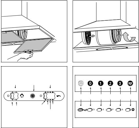
Fig.6 |
|
|
|
A |
B |
|
C |
A1 A2 |
C1 |
C2 |
C4 |
|
C3 |
||
|
|
||
Fig.8 |
|
|
|
|
|
|
|
|
90° |
Fig.7 |
|
|
|
|
|
A |
|
|
|
|
|
G |
B |
C |
D |
E |
A |
B
Fig.9
- 4 -

ENGLISH |
GB |
GENERAL
Carefully read the following important information regarding installation safety and maintenance. Keep this information booklet accessible for further consultations.
The appliance has been designed for use in the ducting version (air exhaust to the outside – Fig.1B), filtering version (air circulation on the inside – Fig.1A) or with external motor (Fig.1C).
SAFETY PRECAUTION
1. Take care when the cooker hood is operating simultaneously with an open fireplace or burner that depend on the air in the environment and are supplied by other than electrical energy, as the cooker hood removes the air from the environment which a burner or fireplace need for combustion. The negative pressure in the environment must not exceed 4Pa (4x10⁻⁵ bar). Provide adequate ventilation in the environment for a safe operation of the cooker hood.
Follow the local laws applicable for external air evacuation.
Before connecting the model to the electricity network:
- control the data plate (positioned inside the appliance) to ascertain that the voltage and power correspond to the network and the socket is suitable. If in doubt ask a qualified electrician.
2.WARNING !
In certain circumstances electrical appliances may be a danger hazard.
A)Do not check the status of the filters while the cooker hood is operating
B)Do not touch bulbs or adjacent areas, during or straight after prolonged use of the lighting installation.
C)Flambè cooking is prohibited underneath the cooker hood
D)Avoid free flame, as it is damaging for the filters and a fire hazard
E)Constantly check food frying to avoid that the overheated oil may become a fire hazard
F)Disconnect the electrical plug prior to any maintenance.
G)This appliance is not intended for use by young children or infirm persons without supervision
H)Young children should be supervised to ensure they do not play with the appliance
I)There shall be adequate ventilation of the room when the rangehood is used at the same time as appliances burning gas or other fuels
L)There is a risk of fire if cleaning is not carried out in accordance with the instructions
INSTALLATION INSTRUCTIONS
Assembly and electrical connections must be carried out by specialised personnel.
• Electric Connection
The appliance has been manufactured as a class II, therefore no earth cable is necessary.
The connection to the mains is carried out as follows: BROWN = L line
BLUE = N neutral
If not provided, connect a plug for the electrical load indicated on the description label. Where a plug is provided, the cooker hood must be installed in order that the plug is easily accessible.
An omnipolar switch with a minimum aperture of 3mm between contacts, in line with the electrical load and local standards, must be placed between the appliance and the network in the case of direct connection to the electrical network.
• The minimum distance between the support surfaces of the cooking pots on the cooker top and the lowest part of the cooker hood must be at least 65 cm.
If a connection tube composed of two parts is used, the upper part must be placed outside the lower part.
Do not connect the cooker hood exhaust to the same conductor used to circulate hot air or for evacuating fumes from other appliances generated by other than an electrical source.
Before proceeding with the assembly operations, remove the anti-grease filter(s) (Fig.6) so that the unit is easier to handle.
In the case of assembly of the appliance in the suction version prepare the hole for evacuation of the air.
• FIXINGTOTHE WALL
Drill the holes A respecting the distances indicated (Fig.2). Fix the appliance to the wall and align it in horizontal position to the wall units. When the appliance has been adjusted, definitely fix the hood using the screws A (Fig.4). For the various installations use screws and screw anchors suited to the type of wall (e.g. reinforced concrete, plasterboard, etc.). If the screws and screw anchors are provided with the product, check that they are suitable for the type of wall on which the hood is to be fixed.
•If your appliance has been designed for use in habitations supplied with acentralised suction device perform the following operations:
-The switch controls opening and closure of a valve using a thermoelectical device. By placing the switch in the ON position, after a minute, the valve opens rotating 90° allowing suction of the stale air. By placing the switch in the OFF position, the valve closes after 100 seconds.
•FIXINGTHE DECORATIVETELESCOPIC FLUE
Arrange the electrical power supply within the dimensions of the decorative flue. If your appliance is to be installed in the ducting version or in the version with external motor, prepare the air exhaust opening. Adjust the width of the support bracket of the upper flue (Fig.3). Then fix it to the ceiling using the screws A (Fig.3) in such a way that it is in line with your hood and respecting
- 5 -

the distance from the ceiling indicated in Fig.2. Connect the flange C to the air exhaust hole using a connection pipe (Fig.4).
Insert the upper flue into the lower flue and rest above the frame.Extract the upper flue up to the bracket and fix it with the screws B (Fig.3). To transform the hood from a ducting version into a filtering version, ask your dealer for the charcoal filters and follow the installation instructions.
• FILTERINGVERSION
Install the hood and the two flues as described in the paragraph for installation of the hood in ducting version. To assemble the filtering flue refer to the instructions contained in the kit. If the kit is not provided, order it from your dealer as accessory.
The filters must be applied to the suction unit positioned inside the hood. They must be centred by turning them 90 degrees until the stop catch is tripped (fig. 7).
USE AND MAINTENANCE
•It is recommended to operate the appliance prior to cooking.
It is recommended to leave the appliance in operation for 15 minutes after cooking is terminated in order to completely eliminate cooking vapours and odours.
The proper function of the cooker hood is conditioned by the regularity of the maintenance operations, in particular, the active carbon filter.
•The anti-grease filters capture the grease particles suspended in the air, and are therefore subject to clogging according to the frequency of the use of the appliance. In order to prevent fire hazard, it is recommendable to clean the filter at a maximum of 2 months by carrying out the following instructions:
- Remove the filters from the cooker hood and wash them in a solution of water and neutral liquid detergent, leaving to soak.
- Rinse thoroughly with warm water and leave to dry. - The filters may also be washed in the dishwasher.
The aluminium panels may alter in colour after several washes. This is not cause for customer complaint nor replacement of panels.
•The active carbon filters purify the air that is replaced in the environment. The filters are not washable nor reuseable and must be replaced at maximum every four months. The saturation of the active carbon filter depends on the frequency of use of the appliance, by the type of cooking and the regularity of cleaning the anti-grease filters.
•Clean the fan and other surfaces of the cooker hood regularly using a cloth moistened with denatured alcohol or non abrasive liquid detergent.
•The illumination installation is designed for use during cooking and not for prolonged general illumination of the environment. Prolonged use of the illumination installation notably reduces the duration of the bulb.
•COMMANDS: (Fig.5) LUMINOUS the key symbols are explained below:
A = LIGHT
B = OFF
C = SPEED I
D = SPEED II
E = SPEED III
F = AUTOMATIC STOP TIMER - 15 minutes
• If your appliance does not have the INTENSIVE speed function, press key E for two seconds and it will be activated for 10 minutes after which it will return to the previously set speed.
When the function is active the LED flashes. To interrupt it before the 10 minutes have expired press key E again.
By pressing key F for two seconds (with the hood switched off) the “clean air” function is activated. This function switches the appliance on for ten minutes every hour at the first speed. As soon as this function is activated the motor starts up at the first speed for ten minutes, During this time key F and key C must flash at the same time. After ten minutes the motor switches off and the LED of key F remains switched on with a fixed light until the motor starts up again at the first speed after fifty minutes and keys F and C start to flash again for ten minutes and so on.
By pressing any key for the exclusion of the hood light the hood will return immediately to its normal functioning (e.g. if key D is pressed the “clean air” function is deactivated and the motor moves to the 2nd speed straight away. By pressing key B the function is deactivated).
•COMMANDS:(Fig.9A)MECHANICAL_(Fig.9B) ELLIptiv the key symbols are explained below:
A = LIGHT
B = OFF
C = SPEED I
D = SPEED II
E = SPEED III
G = MOTOR WORKING indicator
•COMMANDS: (Fig.8) SLIDER the key symbols are explained below:
A = Light switch A1 = Off key A2 = On key
B = Gemma warning light key C = Speed control
C1 = Off key
C2 = FIRST SPEED key
C3 = SECOND SPEED key
C4 = THIRD SPEED key
THE MANUFACTURER DECLINES ALL RESPONSIBILITY FOR EVENTUAL DAMAGES CAUSED BY BREACHING THE ABOVEWARNINGS.
- 6 -

POLSCČESKY
CZ
ÚVOD’
Přečtěte si pozorně obsah návodu, protože poskytuje důležité informace týkající se bezpečné instalace, používání i údržby zařízení. Uchovejte si návod pro jakoukoliv budoucí potřebu. Přístroj je určen k odsávání (odvádění vzduchu ven – obr.1B), filtrování (recyklace vzduchu v místnosti – obr.1A) nebo k použití s externě umístěným motorem (obr.1C).
BEZPECNOSTNÍ OPATRENÍ
1. Vyžaduje se opatrnost, jestliže jsou současně v činnosti odsávač par a jiný hořák nebo tepelné zařízení závisející na vzduchu místnosti a napájené jinou energií než elektrickou, protože odsávač par spotřebovává vzduch z okolí, který hořák nebo jiné tepelné zařízení potřebují ke spalování. Negativní tlak nesmí překročit 4Pa (4x10⁻⁵ bar). K bezpečnému provozu je tedy nutná odpovídající ventilace místnosti. Při odvádění vzduchu do vnějšího prostředí je nutné se řídit platnými předpisy Vaší země.
Před napojením modelu na elektrickou síť:
Zkontrolujte tabulku s údaji umístěnou uvnitř přístroje a ověřte si, že napětí a výkon odpovídají místní síti a rovněž zásuvka je vhodná.
V případě jakékoliv pochyby se poraďte s kvalifikovaným elektrikářem.
2. UPOZORNĚNÍ !
Za určitých okolností mohou být elektrické spotřebiče nebezpečné.
A)Neprovádějte kontrolu filtrů se zapnutým spotřebičem
B)Nedotýkejte se žárovek a prostoru kolem nich behem užití nebo ihned po dlouhodobém užití osvetlovacího zarízení.
C)Nedotýkejte se žárovek, bylo-li zařízení déle v chodu
D)Je zakázáno upravovat pokrmy manipulí přímého ohně pod fungujícím odsávačem
E)Vyvarujte se volnému plameni, je škodlivý pro filtry a mohl by způsobit požár
F)Při smažení jídel zajistěte, aby se rozpálený olej nevznítil
G)Před provedením jakékoliv údržby vypněte přístroj z elektrické sítě.
NÁVOD K INSTALACI
Operace spojené s montáží a elektrická napojení musí být provedeny pouze odborným personálem.
• Elektrické zapojení
Zařízení je vyrobeno v II. třídě, a proto žádný vodič nesmí být uzemněn.
Napojení k elektrické síti musí být provedeno následovně:
HNĚDÁ = L vodič
MODRÁ = N neutrální vodič
Na přívodní kabel, pokud ji již neobsahuje, namontujte zástrčku normalizovanou pro příkon uvedený v technických charakteristikách výrobku.
V případě přímého zapojení na elektrickou síť je nezbytné přístroj připojit přes vícepólový spínač s minimální vzdáleností 3 mm mezi rozpojenými kontakty, dostatečně dimenzovaný a odpovídající platným normám.
• Minimální vzdálenost mezi opěrnou plochou varných nádob na varném zažízení a nejnižším bodem kuchyňského krytu musí být alespoň 65 cm.
Vývod odsavače nesmí být napojen na vývod, ve kterém cirkuluje teplý vzduch, nebo který je používán k odvádění kouře ze zařízení napájených jinou energií než elektrickou. Před zahájením montáže vyjměte z odsavače tukový filtr (obr.6). Usnadníte si tak manipulaci s přístrojem.
V případě montáže přístroje ve verzi odsávače je třeba připravit otvor k evakuaci vzduchu.
• UPEVNĚNÍ KE ZDI
Vyvrtat díry A podle uvedených kót (Obr.2). Odsavač upevněte ke zdi a vyrovnejte jej do horizontální polohy pomocí závěsů. Po vyrovnání odsavač definitivně upevněte prostřednictvím dvou šroubů A (obr.4). Pro různé montážní podmínky použijte příslušné typy šroubů a hmoždinek, které budou odpovídat typu zdiva (např. armovaný beton, sádrokarton atd.). Budou-li šrouby a hmoždinky dodány jako součást produktu, ujistěte se, zda odpovídají typu zdiva, na něž má být odsavač namontován.
•Pokud byl váš přístroj projektován pro používání v bytech vybavených centralizovaným odsávacím systémem, je třeba provést následující operace:
- Pomocí vypínače termoelektrického zařízení dochází k otevírání a zavírání ventilu. Pokud umístíte vypínač do pozice ON, po uplynutí asi jedné minuty se ventil otevře otočením o 90 stupňů a umožní tak odsání zkaženého vzduchu. Pokud umístíte vypínač do pozice OFF, ventil se po 100 vteřinách uzavře.
•MONTÁŽ DEKORATIVNÍCH TELESKOPICKÝCH SPOJOVACÍCH PRVKŮ
Elektrický přívod protáhněte pod krytem dekoračního spoje. Má-li být váš přístroj nainstalován ve verzi odsávání nebo v provedení s externě umístěným motorem, proveďte otvor pro odtah vzduchu. Nastavte šířku úchytné konzoly horního spoje (obr .3). Následně ji upevněte ke stropu prostřednictvím šroubů A (obr.3) takovým způsobem, aby byla v ose s vaším odsavačem a dodržujte přitom vzdálenost od stropu, vyznačenou obr.2.
Vsadit horní spojovací prvek do spodního spojovacího prvku a být položena nad skríní.
Spodní spojovací prvek ke krytu, používajíce šrouby B ve výbavě (obr. 4), vysunout horní díl až ke třmenu a upevněte jej pomocí šroubů B (obr. 3). Budete-li chtít změnit funkci zařízení z odsavače na filtrační verzi,
- 7 -

vyžádejte si u vašeho prodejce filtry s aktivním uhlíkem a sledujte montážní pokyny.
• FILTRAČNÍVERZE
Odsavač a spojovací prvky instalovat tak, jak je uvedeno v bodu, který se týká montáže krytu ve verzi odsavače. Při montáži filtrační vložky se řiďte pokyny obsaženými v balení. Není-li souprava ve výbavě, objednejte ji u svého dodavatele jako příslušenství. Filtry musí být aplikovány na odsávací skoupine umístené uvnitr krytu v jeho stredu a je treba jimi otácet o 90 stupnu až do zastavovacího kliknutí.
POUŽITÍ A ÚDRŽBA
•Doporučujeme zapojení přístroje před přípravou jakéhokoliv vařeného pokrmu.
Doporučujeme nechat odsávač zapnutý po 15 minut po dovaření jídel, k úplnému odsátí spotřebovaného vzduchu. Správné fungování odsávače závisí na pravidelném provádění údržby, zvláště operací k čištění filtru proti mastnotám a filtru s aktivním uhlíkem.
•Úkolem filtru proti mastnotám je zadržovat částice tuků rozptýlené ve vzduchu a proto se mohou ucpávat po různě dlouhé době v závislosti na tom, jak často a jakým způsobem je odsávač používán.
V každém případě je zapotřebí filtry očistit alespoň jednou za 2 měsíce a postupovat při tom následovně:
- Odstranit filtry z odsávace a umýt je v roztoku vody a neutrálního tekutého cistícího prostredku a nechat rozpustit špínu.
- Opláchnout rádne pod vlažnou vodou a nechat uschnout. - Filtry lze rovněž umývat v myčce nádobí.
Po několikerém umytí hliníkových panelů může dojít ke změně jejich barvy. Tato skutečnost neopravňuje k reklamaci a žádosti o jejich eventuální výměnu.
•Filtry s aktivním uhlíkem slouží k vyčištění vzduchu, který bude opět uveden do prostředí. Filtry není možné mýt či obnovovat a musejí být vyměňovány minimálně každé čtyři měsíce. Saturace aktivního uhlíku závisí na délce použití odsávače, typu kuchyně a pravidelnosti čištění filtru proti mastnotám.
•Očistit pravidelně všechny usazeniny na ventilátoru a ostatním povrchu a použít k tomu hadr navlhčený v denaturovaném lihu nebo v neutrálních, nebrusných tekutých čistících prostředcích.
•Osvetlovací zarízení je projektováno pro užití behem varení a nikoliv pro prodloužené použití za úcelem celkového osvetlení prostredí. Nadmerné použití osvetlovacého zarízení podstatne sníží prumerné trvání žárovek.
POVELY: (Obr.5) Světelné
A = przycisk OŚWIETLENIE B = przycisk WŁĄCZENIE
C = przycisk PIERWSZA PRĘDKOŚĆ D = przycisk DRUGA PRĘDKOŚĆ
E = przycisk TRZECIA PRĘDKOŚĆ
F = przycisk REGULATOR CZASOWY AUTOMATYCZNEGO
WYŁĄCZENIA po 15 minutach
Pokud je váš prístroj vybven funkcí INTENZÍVNÍ rychlost, je treba stisknout po dobu aespon 2 s tlacítko E a rychlost bude aktivována po deset minut a poté se vrátí do rychlosti, jež byla předem nastavena.
Pokud je funkce aktivní, led bliká. Chcete –li ji přerušit před vypršením 10 minut, stiskněte znovu klávesu E.
Po stisknutí tlacítka F po dobu 2 s (kryt je vypnut) bude aktivována funkce „clean air“. Tato funkce zapne motor na deset minut každou hodinuna první rychlost. Jakmile bude tato funkce aktivována, motor bude uveden do chodu na první rychlost po dobu 10 s, behem které budou blikat soucasne tlacítka F a C. Po uplynutí této doby se motor vypne a led tlacítka F zustane osvetlen až do doby, kdy po 50 minutách bude znovu motor uveden do chodu na první rychlost a led F a C znovu zacnou blikat po 10 minut a tak dále. Po stisknutí jakéhokoliv tlacítka s výjimkou svetel se kryt okamžite vrátí do svého normálního fungování. (napr. pokud se stiskne tlacítko D, deaktivuje se funkce „clean air“ a motor zacne pracovat na druhou rychlost, stisknutím tlacítka B se tato funkce deaktivuje.
POVELY: Mechanické (Obr.9A)_Elipsa (obr.9B) A = przycisk OŚWIETLENIE
B = przycisk WŁĄCZENIE
C = przycisk PIERWSZA PRĘDKOŚĆ D = przycisk DRUGA PRĘDKOŚĆ
E = przycisk TRZECIA PRĘDKOŚĆ
G = wskaźnik SILNIK FUNKCJONUJĄCY
• Ovládací povely (obr. 8) SLIDER – symbologie je následující:
A = svetelný spínac A1 = tlacítko vypnout A2 = tlacítko zapnout
D = tlacítko Gemma kontrola C = kontrola rychlosti
C1 = tlacítko vypnout
C2 = tlacítko PRVNÍ RYCHLOST
C3 = tlacítko DRUHÁ RYCHLOST
C4 = tlacítko TRETÍ RYCHLOST
VÝROBCE ODMÍTÁ JAKOUKOLIV ZODPOVĚDNOST ZA ŠKODY ZPŮSOBENÉ NEDODRŽENÍM UVEDENÝCH UPOZORNĚNÍ.
- 8 -

DANSK |
DK |
GENERELLE OPLYSNINGER
Læs omhyggeligt indholdet af denne brugsanvisning, da den giver vigtige oplysninger vedrørende sikkerheden ved installering, brug og vedligeholdelse.
Opbevar brugsanvisningen til senere brug.
Apparatet er udarbejdet til at kunne fungere; udsugende (udledning af luft til eksterne omgivelser Fig.1B) filtrerende (intern cirkulation af luft Fig.1A) og med udvendig motor. (Fig.1C).
OPLYSNINGER VEDRØRENDE SIKKERHED
1. Udvis forsigtighed hvis der samtidigt med emhætten er en varmekilde eller flamme i funktion, som er afhængig af luften i omgivelserne og forsynet med energi, der ikke er elektrisk, eftersom emhætten fjerner den luft fra omgivelserne, som flammen eller varmekilden har brug for til forbrænding.
Det negative tryk i lokalet må ikke overstige 4 Pa (4x10⁻⁵ bar). For størst mulig sikkerhed, sørg for en passende ventilation af rummet. Hvad angår udsugningen til eksterne omgivelser følg de gældende normer.
Før modellen tilsluttes el-nettet:
-Kontrollèr informationsetiketten (placeret indeni apparatet), for at sikre, at spændingen og styrken er i overensstemmelse med el-nettet og at stikkontakterne er egnede. Hvis De er i tvivl, konsultèr en kvalificeret elektriker.
2. ADVARSEL!
I bestemte situationer kan elektriske hvidevarer være farlige.
A)Forsøg ikke at kontrollere filtrene mens emhætten er tændt.
B)Rør ikke ved pærer eller områderne omkring dem i forbindelse med længere brug af belysningsanlægget eller straks herefter.
C)Rør ikke ved lamperne efter længerevarende brug af apparatet.
D)Det er forbudt at flambere under emhætten.
E)Undgå åben flamme da det er skadelig for filtrene og kan forårsage brand.
F)Hold friturestegning under konstant overvågning for at undgå, at olien overophedes og bryder i brand.
G)Før man udføre enhver form for vedligeholdelse skal emhætten være afbrudt fra el-nettet.
INSTRUKTION VED INSTALLERING
Monteringen og udførelsen af de elektriske forbindelser, skal udføres af specialiseret personale.
Den elektriske forbindelse.
Apparatet er udarbejdet i klasse II, derfor skal der ikke tilsluttes et kabel til jordforbindelsen.
Tilslutning til el-nettet skal udføres som følgende: BRUN = L Linje
BLÅ = N Neutal
Hvis det ikke allerede findes, montèr da et standardstik beregnet til den forsyning, som er angivet på etiketten.Hvis der allerede er et stik, sørg da for at det er let tilgængelig efter installation af apparatet.
I tilfælde af en direkte tilslutning til el-nettet er det nødvendigt at anbringe en flerpolet afbryder med en afstand mellem kontakterne på minimum 3 mm, mellem apparatet og nettet. Afbryderen skal passe til elforsyningen og være i overenstemmelse med de gældende normer.
• Minimums distancen mellem kogeoverfladen, målt fra selve kogepladerne, og den nederste del af emhhætten, skal være mindst 65 cm.
Hvis der anvendes et forbindelsesrør bestående af to eller flere dele, skal den øverste del placeres udenpå den nederste.
Tilslut ikke udledningen fra emhætten med et rør, hvori der cirkulere varm luft eller som anvendes til at udlede røg fra apparater, der ikke bruger elektrisk energi.
Inden man begynder monteringen fjernes filtret (Fig.6) for at gøre håndteringen af apparatet lettere.
I de tilfælde, hvor apparatet skal installeres i en udsugende version, forberedes åbningen til udledning af luft.
• FASTSPÆNDINGTILVÆG
Lav hullerne A , idet de anviste mål overholdes (Fig.2). Fastspænd apparatet til væggen og ret ind, til det flugter med ophænget. Når apparatet er i vater, spændes emhætten fast ved hjælp af de 2 skruer A (Fig.4).Til forskellige typer montering anvendes skruer og rawlplugs, der passer til den bestemte type mur (f.eks. jernbeton, gips osv. ). Hvis skruer og rawlplugs følger med apparatet, bør man sikre sig, at de egner sig til væggen, hvor emhætten skal spændes fast.
•Hvis Deres apparat skal placeres i en bolig, som er udstyret med en centraliseret udsugning, gør som følgende:
-Afbryderen styrer åbningen og lukningen af en ventil ved hjælp af en termoelektrisk anordning. Drej afbryderen i ON position, efter et minut åbnes ventilen med en drejning på 90° og igangsætter dermed udsugningen af den dårlige luft. Ved at dreje afbryderen i OFF position lukkes ventilen efter 100 sekunder.
•FASTSPÆNDING AF DE SAMMENSKYDELIGE PYNTEPANELER
Indsæt El-tilslutningen i rillen på panelet. Hvis apparatet skal installeres som aftræksemhætte eller med udvendig motor, laves først hul til udsugning af luften. Regulér bredden på det øverste panels ophæng (Fig.3). Spænd herefter ophænget fast til loftet med skruerne A (Fig.3), så det er i vinkel med emhætten, idet den anviste afstand til loftet i Fig.2 overholdes.
Forbind flangen C til udsugningshullet ved hjælp af et tilslutningsrør (Fig.4).
Indsæt det øverste panel i det nederste og anbringe oven
- 9 -
 Loading...