

Page 1
SERVICE STATION MANUAL
894159
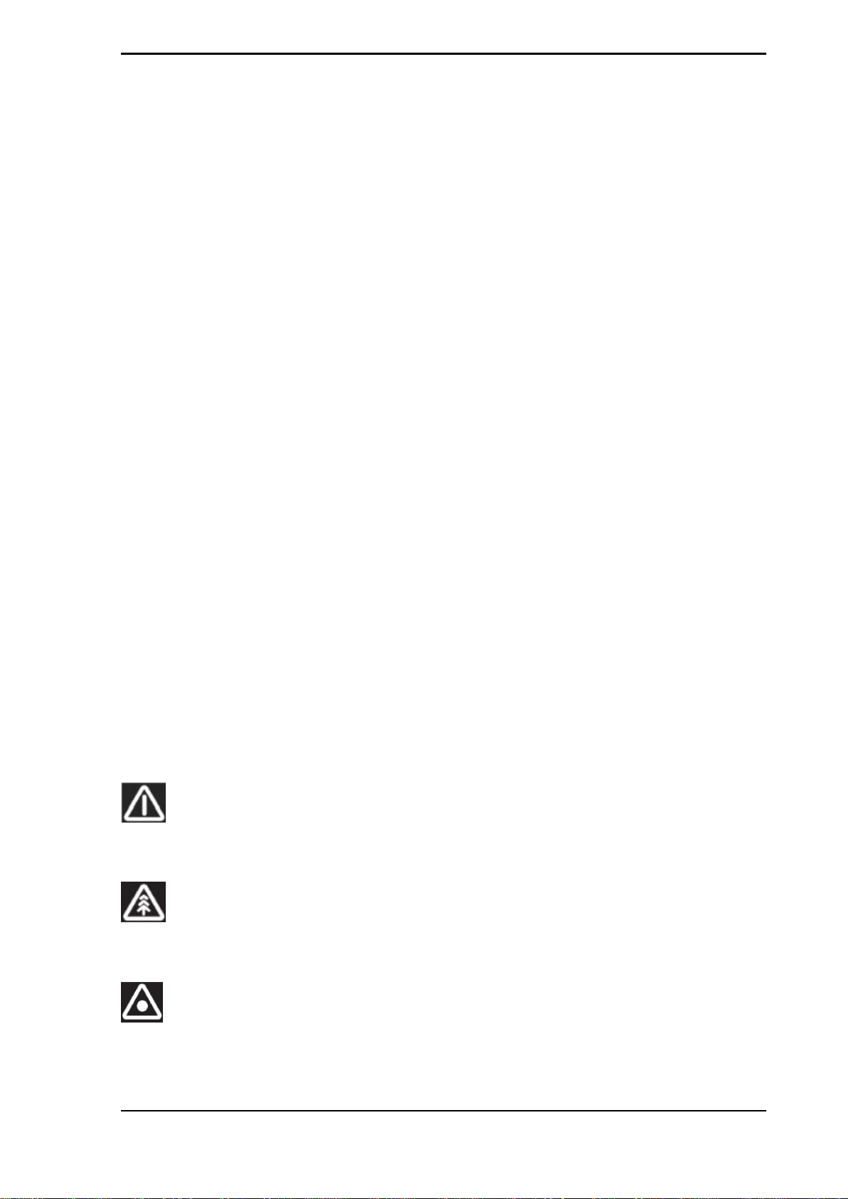
RSV4 Factory
Page 2

SERVICE STATION
MANUAL
RSV4 Factory
THE VALUE OF SERVICE
Due to the continuous technical updates and specific mechanic training programs for aprilia products,
only aprilia Official Network mechanics know this vehicle fully and have the special tools necessary to
carry out maintenance and repair operations correctly.
The reliability of the vehicle also depends on its mechanical state. Checking the vehicle before riding, its
regular maintenance and using only Original aprilia Spare Parts are essential!
For information about the nearest Official Dealer and/or Service Centre, consult the Yellow Pages or
search directly from the map on our Official Website:
www.aprilia.com
Only by requesting aprilia Original Spare Parts can you be sure of purchasing products that were
developed and tested together with the actual vehicle itself. All aprilia Original Spare Parts undergo
quality control procedures to guarantee reliability and durability.
The descriptions and illustrations given in this publication are not binding; While the basic characteristics
as described and illustrated in this booklet remain unchanged, aprilia reserves the right, at any time and
without being required to update this publication beforehand, to make any changes to components, parts
or accessories, which it considers necessary to improve the product or which are required for
manufacturing or construction reasons.
Not all versions/models shown in this publication are available in all Countries. The availability of
individual versions/models should be confirmed with the official aprilia sales network.
© Copyright 2009 aprilia. All rights reserved. Reproduction of this publication in whole or in part is
prohibited. aprilia - After-sales service.
Aprilia trademark is property of Piaggio & C. S.p.A.
Page 3
SERVICE STATION MANUAL
RSV4 Factory
- This manual provides the main information to carry out regular maintenance operations on your vehicle.
- This manual is intended to aprilia Dealers and their qualified mechanics; several concepts have been
deliberately omitted as they are considered unnecessary. As it is not possible to include complete
mechanical notions in this manual, users should have basic mechanical knowledge or minimum
knowledge about the procedures involved when repairing scooters. Without this knowledge, repairing or
checking the vehicle may be inefficient or even dangerous. As the vehicle repair and check procedures
are not described in detail, be extremely cautious so as not to damage components or injure individuals.
In order to optimise customer satisfaction when using our vehicles, aprilia s.p.a. commits itself to
continually improve its products and the relative documentation. The main technical modifications and
changes in repair procedures are communicated to all aprilia Sales Outlets and its International
Subsidiaries. These changes will be introduced in the subsequent editions of the manual. In case of need
or further queries on repair and check procedures, consult aprilia CUSTOMER DEPARTMENT, which
will be prepared to provide any information on the subject and any further communications on updates
and technical changes related to the vehicle.
NOTE Provides key information to make the procedure easier to understand and carry out.
CAUTION Refers to specific procedures to carry out for preventing damages to the vehicle.
WARNING Refers to specific procedures to carry out to prevent injuries to the repairer.
Personal safety Failure to completely observe these instructions will result in serious risk of personal
injury.
Safeguarding the environment Sections marked with this symbol indicate the correct use of the vehicle
to prevent damaging the environment.
Vehicle intactness The incomplete or non-observance of these regulations leads to the risk of serious
damage to the vehicle and sometimes even the invalidity of the guarantee.
Page 4

Page 5

INDEX OF TOPICS
CHARACTERISTICS CHAR
SPECIAL TOOLS S-TOOLS
MAINTENANCE MAIN
TROUBLESHOOTING TROUBL
ELECTRICAL SYSTEM ELE SYS
ENGINE FROM VEHICLE ENG VE
ENGINE ENG
POWER SUPPLY P SUPP
SUSPENSIONS SUSP
CHASSIS CHAS
BRAKING SYSTEM BRAK SYS
COOLING SYSTEM COOL SYS
BODYWORK BODYW
PRE-DELIVERY PRE DE
Page 6

INDEX OF TOPICS
CHARACTERISTICS CHAR
Page 7
RSV4 Factory Characteristics
Rules
Safety rules
Carbon monoxide
If you need to keep the engine running while working on the vehicle, please ensure that you do so in
an open or very well ventilated area. Never run the engine in an enclosed area. If you do work in an
enclosed area, make sure to use a fume extraction system.
CAUTION
EXHAUST EMISSIONS CONTAIN CARBON MONOXIDE, A POISONOUS GAS WHICH CAN CAUSE
LOSS OF CONSCIOUSNESS AND EVEN DEATH.
Fuel
CAUTION
THE FUEL USED TO POWER INTERNAL COMBUSTION ENGINES IS HIGHLY FLAMMABLE AND
MAY BE EXPLOSIVE UNDER CERTAIN CONDITIONS. IT IS THEREFORE RECOMMENDED TO
CARRY OUT REFUELLING AND MAINTENANCE PROCEDURES IN A VENTILATED AREA WITH
THE ENGINE SWITCHED OFF. DO NOT SMOKE DURING REFUELLING OR NEAR FUEL VAPOUR.
AVOID ANY CONTACT WITH NAKED FLAME, SPARKS OR OTHER HEAT SOURCES WHICH MAY
CAUSE IGNITION OR EXPLOSION.
DO NOT ALLOW FUEL TO DISPERSE INTO THE ENVIRONMENT.
KEEP OUT OF REACH OF CHILDREN
Hot components
The engine and the exhaust system components become very hot and remain hot for some time after
the engine has been switched off. When handling these components, wear insulating gloves or wait
until the engine and the exhaust system have cooled down.
Coolant
The coolant contains ethylene glycol which, under certain conditions, can become flammable.
When it burns, ethylene glycol produces an invisible flame which however can cause burns.
CAUTION
TAKE CARE NOT TO SPILL COOLANT ONTO HOT ENGINE OR EXHAUST SYSTEM COMPONENTS; THE FLUID MAY IGNITE AND BURN WITH AN INVISIBLE FLAME. WHEN CARRYING
OUT MAINTENANCE, IT IS ADVISABLE TO WEAR LATEX GLOVES. EVEN THOUGH IT IS TOXIC,
COOLANT HAS A SWEET FLAVOUR WHICH MAKES IT VERY ATTRACTIVE TO ANIMALS. NEVER LEAVE THE COOLANT IN OPEN CONTAINERS IN AREAS ACCESSIBLE TO ANIMALS AS
THEY MAY DRINK IT.
CHAR - 7
Page 8
Characteristics RSV4 Factory
KEEP OUT OF REACH OF CHILDREN
DO NOT REMOVE THE RADIATOR CAP WHEN THE ENGINE IS STILL HOT. THE COOLANT IS
PRESSURISED AND MAY CAUSE SCALDING.
Used engine oil and transmission oil
CAUTION
IT IS ADVISABLE TO WEAR LATEX GLOVES WHEN SERVICING THE VEHICLE.
THE ENGINE OR GEARBOX OIL MAY CAUSE SERIOUS INJURIES TO THE SKIN IF HANDLED
FOR PROLONGED PERIODS OF TIME AND ON A REGULAR BASIS.
WASH YOUR HANDS CAREFULLY AFTER HANDLING OIL.
HAND THE OIL OVER TO OR HAVE IT COLLECTED BY THE NEAREST USED OIL RECYCLING
COMPANY OR THE SUPPLIER.
DO NOT DISPOSE OF OIL IN THE ENVIRONMENT
KEEP OUT OF REACH OF CHILDREN
THE BRAKE FLUID MAY DAMAGE PAINTED, PVC OR RUBBER SURFACES. WHEN SERVICING
THE BRAKING SYSTEM, PROTECT THESE COMPONENTS WITH A CLEAN CLOTH. ALWAYS
WEAR PROTECTIVE GOGGLES WHEN SERVICING THE BRAKING SYSTEM. THE BRAKE FLUID
IS EXTREMELY DANGEROUS TO THE EYES. IN THE EVENT OF ACCIDENTAL CONTACT WITH
THE EYES, RINSE THEM IMMEDIATELY WITH PLENTY OF COLD, CLEAN WATER AND SEEK
MEDICAL ADVICE.
KEEP OUT OF REACH OF CHILDREN
Battery electrolyte and hydrogen gas
CAUTION
THE BATTERY ELECTROLYTE IS TOXIC, CORROSIVE AND, AS IT CONTAINS SULPHURIC
ACID, MAY CAUSE BURNING IF IT COMES INTO CONTACT WITH THE SKIN. WHEN HANDLING
BATTERY ELECTROLYTE, WEAR TIGHT-FITTING GLOVES AND PROTECTIVE APPAREL. IN
THE EVENT OF SKIN CONTACT WITH THE ELECTROLYTIC FLUID, RINSE WELL WITH PLENTY
OF CLEAN WATER. IT IS PARTICULARLY IMPORTANT TO PROTECT YOUR EYES BECAUSE
EVEN TINY AMOUNTS OF BATTERY ACID MAY CAUSE BLINDNESS. IN THE EVENT OF CONTACT WITH THE EYES, RINSE WITH PLENTY OF WATER FOR FIFTEEN MINUTES AND CONSULT AN EYE SPECIALIST IMMEDIATELY. IF THE FLUID IS ACCIDENTALLY SWALLOWED,
DRINK LARGE QUANTITIES OF WATER OR MILK, FOLLOWED BY MILK OF MAGNESIA OR
VEGETABLE OIL AND SEEK MEDICAL ADVICE IMMEDIATELY. THE BATTERY RELEASES EXPLOSIVE GASES; KEEP IT AWAY FROM FLAMES, SPARKS, CIGARETTES OR ANY OTHER
HEAT SOURCES. ENSURE ADEQUATE VENTILATION WHEN SERVICING OR RECHARGING
THE BATTERY.
KEEP OUT OF REACH OF CHILDREN
BATTERY LIQUID IS CORROSIVE. DO NOT POUR OR SPILL ON PLASTIC COMPONENTS IN
PARTICULAR. ENSURE THAT THE ELECTROLYTIC ACID IS COMPATIBLE WITH THE BATTERY
BEING ACTIVATED.
Maintenance rules
GENERAL PRECAUTIONS AND INFORMATION
CHAR - 8
Page 9

RSV4 Factory Characteristics
When repairing, dismantling and reassembling the vehicle, follow the recommendations given below
carefully.
BEFORE REMOVING COMPONENTS
•
Before dismantling components, remove dirt, mud, dust and foreign bodies from the vehicle.
Use the special tools designed for this bike, as required.
COMPONENTS REMOVAL
•
Do not loosen and/or tighten screws and nuts using pliers or any other tools than the specific
wrench.
•
Mark positions on all connection joints (pipes, cables etc.) before separating them, and
identify them with distinctive symbols.
•
Each component needs to be clearly marked to enable identification during reassembly.
•
Clean and wash the dismantled components carefully using a low-flammability detergent.
•
Keep mated parts together since they have "adjusted" to each other due to normal wear.
•
Some components must be used together or replaced completely.
•
Keep away from heat sources.
REASSEMBLING COMPONENTS
CAUTION
BEARINGS MUST ROTATE FREELY, WITHOUT JAMMING AND/OR NOISE, OTHERWISE, THEY
NEED TO BE REPLACED.
•
Only use ORIGINAL aprilia SPARE PARTS.
•
Comply with lubricant and consumables use guidelines.
•
Lubricate parts (whenever possible) before reassembling them.
•
When tightening nuts and screws, start either from the components with the largest diameter
or from the innermost components, proceeding diagonally. Tighten nuts and screws in successive steps before applying the tightening torque.
•
Always replace self-locking nuts, washers, sealing rings, circlips, O-rings (OR), split pins
and screws with new parts if the thread is damaged.
•
When assembling the bearings, make sure to lubricate them well.
•
Check that each component is assembled correctly.
•
After a repair or routine maintenance, carry out pre-ride checks and test the vehicle on
private grounds or in an area with low traffic.
•
Clean all mating surfaces, oil seal rims and gaskets before refitting. Smear a thin layer of
lithium-based grease on the oil seal rims. Reassemble oil seals and bearings with the brand
or batch number facing outward (visible side).
ELECTRIC CONNECTORS
Electric connectors must be disconnected as described below; failure to comply with this procedure
causes irreparable damage to both the connector and the wiring harness:
Press the relative safety clips, if applicable.
CHAR - 9
Page 10
Characteristics RSV4 Factory
•
Grip the two connectors and disconnect them by pulling them in opposite directions.
•
If any signs of dirt, rust, moisture, etc. are noted, clean the inside of the connector carefully
with a jet of compressed air.
•
Ensure that the cables are correctly fastened to the internal connector terminals.
•
Then connect the two connectors, ensuring that they couple correctly (if fitted with clips, you
will hear them "click" into place).
CAUTION
DO NOT DISCONNECT CONNECTORS BY PULLING THE CABLES.
NOTE
THE TWO CONNECTORS CAN ONLY BE CONNECTED IN ONE DIRECTION: CONNECT THEM
THE RIGHT WAY ROUND.
TIGHTENING TORQUES
CAUTION
REMEMBER THAT THE TIGHTENING TORQUES FOR ALL FASTENING ELEMENTS ON WHEELS,
BRAKES, WHEEL BOLTS AND ANY OTHER SUSPENSION COMPONENTS PLAY A KEY ROLE
IN ENSURING VEHICLE SAFETY AND MUST COMPLY WITH SPECIFIED VALUES. CHECK THE
TIGHTENING TORQUES OF FASTENING ELEMENTS ON A REGULAR BASIS AND ALWAYS USE
A TORQUE WRENCH TO REASSEMBLE THESE COMPONENTS. FAILURE TO COMPLY WITH
THESE RECOMMENDATIONS MAY CAUSE ONE OF THESE COMPONENTS TO LOOSEN OR
EVEN DETACH, CAUSING A WHEEL TO LOCK OR COMPROMISING VEHICLE HANDLING. THIS
MAY LEAD TO FALLS, WITH THE RISK OF SERIOUS INJURY OR DEATH.
Running-in
Running the engine in correctly is essential for ensuring engine longevity and functionality. Twisty roads
and gradients are ideal for running in the engine, brakes and suspension effectively. Vary your riding
speed during the running in period. This ensures that components operate in "loaded" conditions and
then "unloaded" conditions, allowing the engine components to cool.
CAUTION
THE FULL PERFORMANCE OF THE VEHICLE IS ONLY AVAILABLE AFTER THE SERVICE AT
THE END OF THE RUNNING IN PERIOD.
Follow the guidelines detailed below:
•
Do not fully open the throttle grip abruptly at low engine speeds, either during or after the
running in period.
•
During the first 100 Km (62 miles) use the brakes gently, avoiding sudden or prolonged
braking. This allows the brake pad friction material to bed in correctly with the brake discs.
•
Preferably do not exceed 7500 rpm during the first 1000 km (621 mi) and 9500 rpm from
1000 to 2000 km (1243 mi).
AFTER THE SPECIFIED MILEAGE, TAKE YOUR VEHICLE TO AN Official aprilia Dealer FOR THE
CHECKS INDICATED IN THE "SCHEDULED MAINTENANCE" TABLE IN THE SCHEDULED MAINTENANCE SECTION TO AVOID INJURY TO YOURSELF OR OTHERS AND /OR DAMAGING THE
VEHICLE.
CHAR - 10
Page 11
RSV4 Factory Characteristics
Vehicle identification
SERIAL NUMBER LOCATION
These numbers are necessary for vehicle registration.
NOTE
ALTERING IDENTIFICATION NUMBERS MAY BE SERIOUSLY PUNISHABLE BY LAW. IN PARTICULAR, MODIFYING THE CHASSIS NUMBER IMMEDIATELY VOIDS THE WARRANTY.
This number consists of numbers and letters, as in
the example shown below.
ZD4RK0000YSXXXXXX
KEY:
ZD4: WMI (World manufacturer identifier) code;
RK: model;
000: version variation;
0: free digit
Y year of manufacture
S: production plant (S= Scorzè);
XXXXXX: serial number (6 digits);
CHASSIS NUMBER
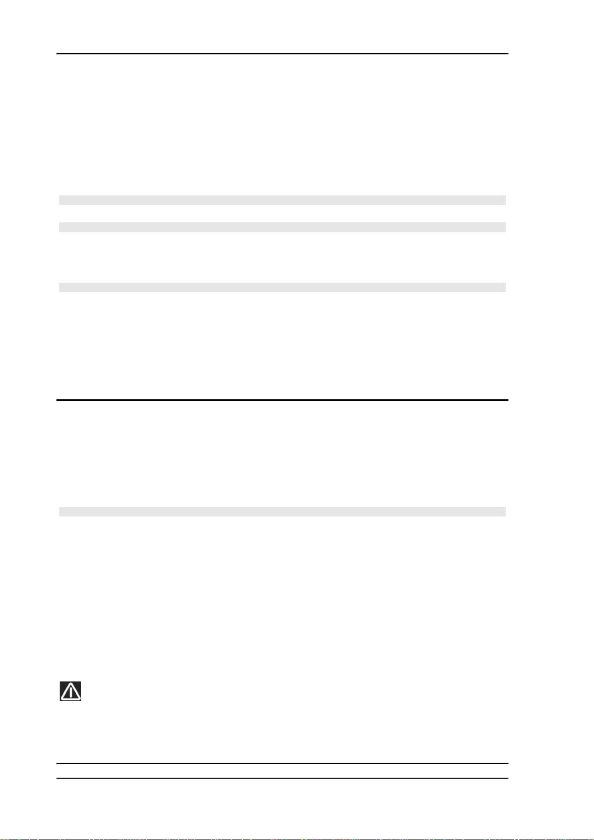
The chassis number is stamped on the right hand
side of the headstock.
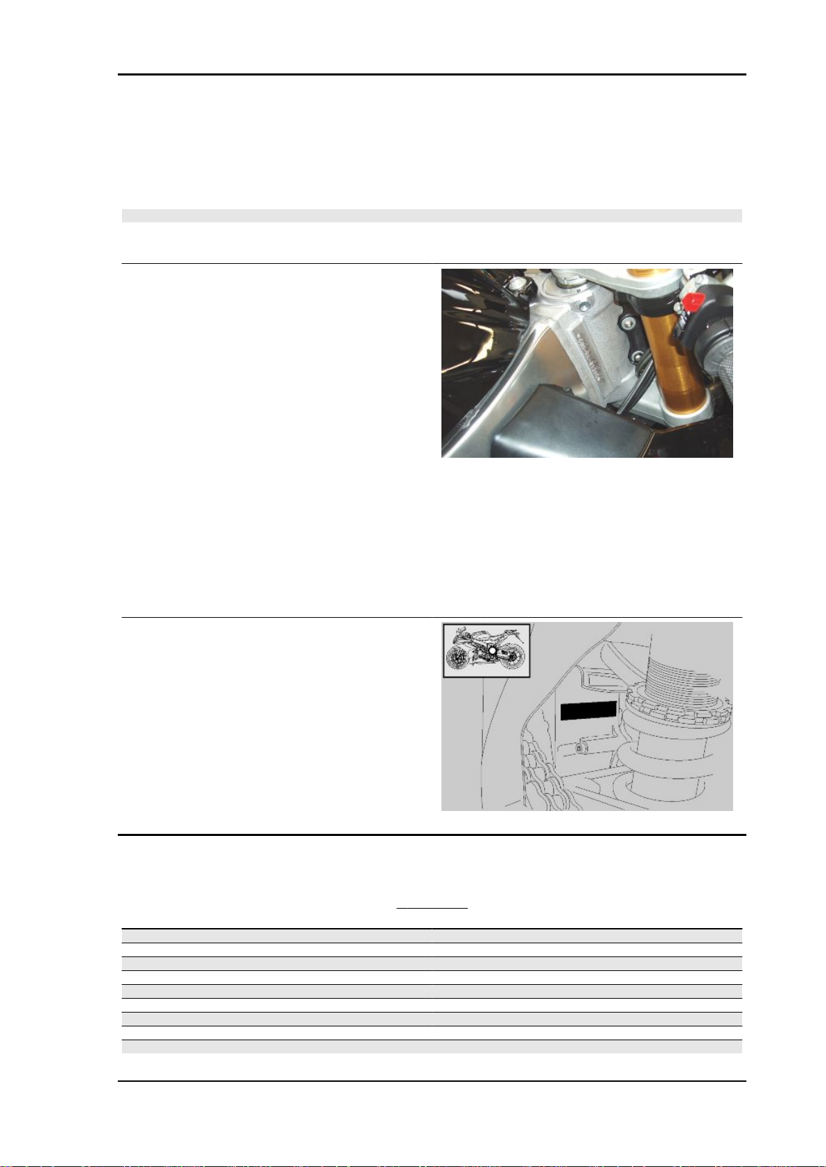
ENGINE NUMBER
The engine number is printed on the base of the
engine crankcase, left hand side.
Engine No. ....................
Dimensions and mass
DIMENSIONS
Specification
Max. length 2040 mm (80.31 in)
Max width (at handlebar) 735 mm (28.94 in)
Max. height (to windshield) 1120 mm (44.09 in)
Saddle height 847 mm (33.35 in)
Wheelbase 1420 mm (55.90 in)
Minimum ground clearance 130 mm (5.12 in)
Kerb weight 189 kg (417 lb)
Kerb weight 200 kg (441 lb)
Full loaded weight (rider only) 275 kg (441 lb)
Desc./Quantity
CHAR - 11
Page 12
Characteristics RSV4 Factory
Engine
ENGINE
Specification Desc./Quantity
Model V4
Type 65° longitudinal V-4, 4-stroke, 4 valves per cylinder, double
Engine capacity 999 cm³ (60.96 cu.in)
Bore / stroke 78 mm / 52.26 mm (3.07 in / 2.06 in)
Compression ratio 13 : 1
Engine speed at idle 1400 ± 100 rpm
Engine revs at maximum speed 14000 ± 100 rpm
Clutch Multiplate wet clutch with mechanical control lever on left side
Ignition electronic
TIMING SYSTEM Morse chain on intake camshaft, cam to cam gear, bucket tap-
Acceptable values with control clearance between cam and
valve
Lubrication system Wet sump with oil radiator
Oil pump Dual trochoidal pump (lubrication + cooling)
Oil filter With external cartridge filter
Cooling Fluid
Cooling system 3-way thermostatic valve, cooling radiator with electric fan and
Coolant pump Centrifugal bearingless aspirating pump with integrated ce-
Air filter In cotton
of the handlebar Anti-juddering and slipper clutch systems
pets and valve clearance adjustments with calibrated pads
intake: 0.10 - 0.15 mm (0.0039 - 0.0059 in) exhaust: 0.20 - 0.25
overhead camshafts.
mm (0.0079 - 0.0098 in)
expansion tank
ramic gasket
Transmission
Capacities
Fuel capacity (reserve included) 17 l (3.74 UK gal)
Maximum weight capacity 201 kg (443 lb)
GEAR RATIOS
Specification
Primary drive ratio 44 / 73 (with gears)
1st gear ratio 15 / 39 (secondary)
2nd gear ratio 16 / 33 (secondary)
3rd gear ratio 20 / 34 (secondary)
4th gear ratio 22 / 32 (secondary)
5th gear ratio 26 / 34 (secondary)
6th gear ratio 27 / 33 (secondary)
Final drive gear ratio 16 / 40
Desc./Quantity
CAPACITY
Specification
Fuel tank reserve 3.6 l (0.79 UK gal)
Engine oil oil and filter change 4 l (0.88 UK gal)
Coolant 2.4 l (0.53 UK gal)
Seats 1 + 1
Two seat configuration: if vehicle is fitted with footrests and
Desc./Quantity
saddle for passenger
CHAR - 12
Page 13
RSV4 Factory Characteristics
Drive chain
DRIVE CHAIN
Specification Desc./Quantity
Type 525
Model Regina 108 links
Electrical system
ELECTRICAL SYSTEM
Specification Desc./Quantity
Spark plugs NGK-R CR9EB
Electrode gap 0.7 - 0.8 mm (0.027 - 0.031 in)
Battery YUASA YTZ10S, 12 V 8.6 Ah
alternatively YUASA YT12A-BS, 12 V 9.5 Ah
Coils Stick coil
Recharging system Flywheel with rare earth magnets
Alternator 420 W
Main fuses 30 A
Auxiliary fuses 5A - 7.5A - 15A
With sealed master link
NGK-R CR10E (for competition use)
Specification
Low-/ high-beam light 12V - 55W H11
Front daylight running light 12V - 5W
Turn indicators 12V - 10W (White light)
License plate light 12V - 5W
Specification
High-beam light LED
Right turn indicator LED
Left turn indicator LED
General warning LED
Gear in neutral LED
Side stand down LED
Fuel reserve LED
ABS NON ATTIVA
Frame and suspensions
Specification
Type Adjustable aluminium, dual beam chassis with pressed and
Steering inclination angle 26.5° (measurements with reference to bare chassis)
Trail 107 mm (4.21 in)
BULBS
Desc./Quantity
SPIE
Desc./Quantity
CHASSIS
Desc./Quantity
cast sheet elements.
(with adjustable inserts, headstock as a standard feature)
SUSPENSION
Specification
Front fork Ohlins upside down units with adjustable hydraulic damping
and 43 mm (1.69 in) diam. stanchions with Tin surface coating)
Front wheel travel 120 mm (4.72 in)
Rear shock absorber Lateral mounted hydraulic shock absorber with progressive
APS system. OHLINS shock absorbers with adjustable piggy-
Desc./Quantity
CHAR - 13
Page 14
Characteristics RSV4 Factory
Specification Desc./Quantity
back preload, centre to centre distance and hydraulic brake in
Rear wheel travel 130 mm (5.12 in)
compression and rebound damping
SIZES A AND B
Specification Desc./Quantity
Size "A" 639.5 mm (25.18 in) (measurements refer to the bare chassis)
Size "B" 329.5 mm (12.97 in) (measurements refer to the bare chassis)
Brakes
Specification
Wheels and tyres
Specification
Front wheel rim 3.50 x 17"
Rear wheel rim 6.00 x 17"
Specification
Tyre model Pirelli DIABLO Super Corsa SP
Front tyre 120/70 ZR17 (58W)
Inflation pressure 1 passenger: 2.3 bar (230 kPa) (33.36 PSI)
Rear tyre 190/55 ZR17 (75W)
Inflation pressure 1 passenger: 2.5 bar (250 kPa) (36.26 PSI)
BRAKES
Desc./Quantity
Front With dual floating disc 320 mm diam. (12.59 inches), enbloc
calipers with radial fixing and four pistons 34 mm diam. (1.34
inches) and 4 pads - radial pump and brake pipe in metal braid.
Rear disc type -220 mm diam. (8.66 inches), 2-piston calipers - 32
mm diam. (1.25 inches) - pump with built-in tank and metal
braid pipe.
WHEEL RIMS
Desc./Quantity
TYRES
Desc./Quantity
Metzeler RACETEC K3
Michelin Power One
Dunlop SPORTMAX GP Racer (Mixture "M" Front)
Dunlop SPORTMAX GP Racer (Mixture "E" Rear)
2 passengers: 2.5 bar (250 kPa) (36.26 PSI)
190/50 ZR17 (73W)
2 passengers: 2.8 bar (280 kPa) (40.61 PSI)
CHAR - 14
Page 15
RSV4 Factory Characteristics
Supply
FUEL SYSTEM
Specification Desc./Quantity
Fuel Premium unleaded petrol, minimum octane rating of 95
FUEL SYSTEM
Specification Desc./Quantity
Throttle body diameter 48 mm (1.89 in)
Type Electronic injection with 2 injectors per cylinder, 4 throttle bod-
ies motorised (Ride by wire). Intake cones at variable height. 2
Tightening Torques
Chassis
(NORM) and 85 (NOMM)
dynamic air intakes. Selectable multimap.
Front side
pos.
1 Screws fastening oil radiator to
Description Type Quantity Torque Notes
mounting bracket
OIL RADIATOR
M6 1 7 Nm (5.16 lbf ft) -
CHAR - 15
Page 16
Characteristics RSV4 Factory
pos.
1 Fastener screws for calliper mount-
Description Type Quantity Torque Notes
ing bracket (Öhlins)
FRONT FORK
M6 2 + 2 12 Nm (8.85 lbf ft) -
CHAR - 16
Page 17
RSV4 Factory Characteristics
STEERING
pos. Description Type Quantity Torque Notes
1 Screws fastening upper yoke to stan-
chions
2 Screws fastening lower yoke to stan-
chions
3 Headstock ring nut M35x1 1 60 Nm (44.25 lbf ft) 4 Headstock counter ring nut M35x1 1 Manual +35° or -10° 5 Upper yoke fixing cap - 1 100 Nm (73.76 lbf ft) 6 Screw fastening shock absorber to
frame
7 Screw fastening shock absorber to
lower yoke
M8 2 25 Nm (18.44 lbf ft) M8 4 25 Nm (18.44 lbf ft) -
M6 1 10 Nm (7.37 lbf ft) M6 1 10 Nm (7.37 lbf ft) -
FRONT WHEEL
pos.
1 Front wheel spindle nut M25x1.5 1 80 Nm (59 lbf ft) 2 Front brake disc fixing screws M8 6 + 6 30 Nm (22.13 lbf ft) Loct. 243
Description Type Quantity Torque Notes
CHAR - 17
Page 18
Characteristics RSV4 Factory
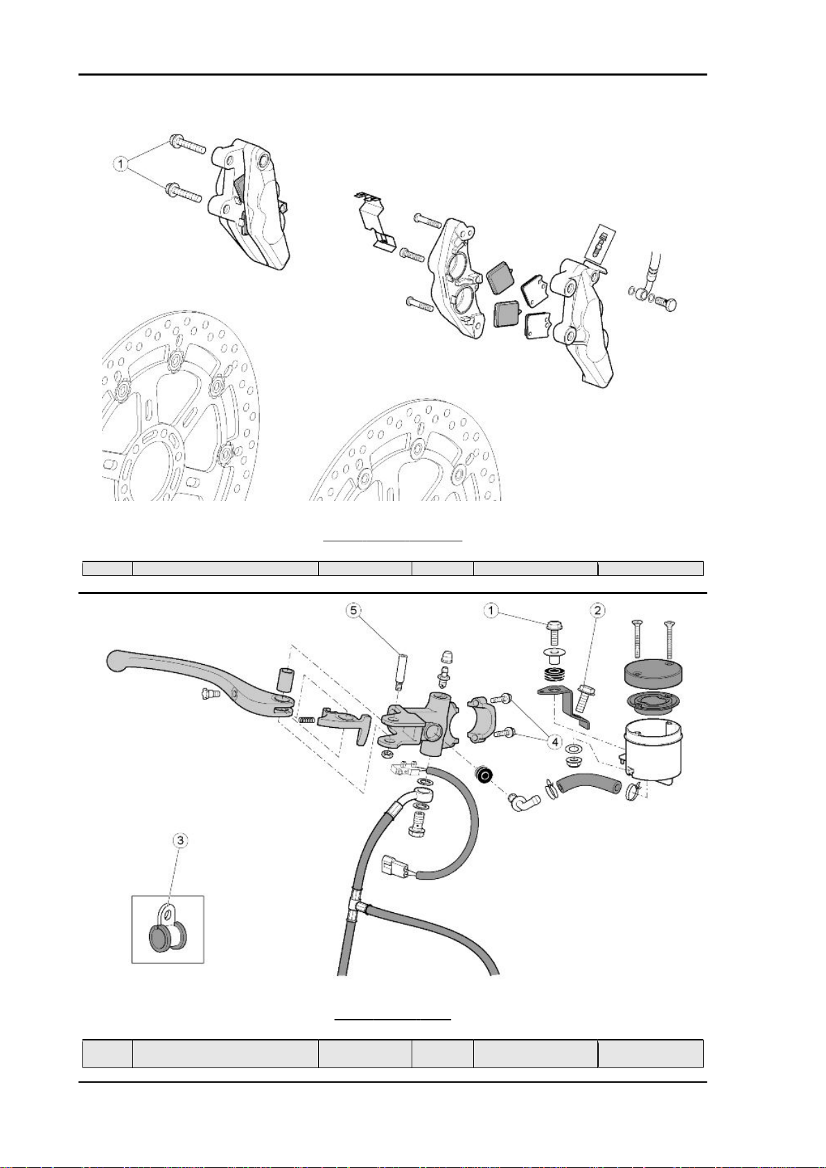
FRONT BRAKE CALLIPER
pos.
1 Front brake calliper fixing screws M10x1.25 2 + 2 50 Nm (36.88 lbf ft) -
Description Type Quantity Torque Notes
pos.
1 Screw fastening front brake fluid res-
Description Type Quantity Torque Notes
ervoir to bracket
CHAR - 18
FRONT BRAKE PUMP
M6 1 7 Nm (5.16 lbf ft) -
Page 19

RSV4 Factory Characteristics
pos. Description Type Quantity Torque Notes
2 Screw fastening brake fluid reservoir
mounting bracket to handlebar
3 Screw fastening brake pipe grommet
to the lower yoke
4 Front brake pump U bolt clamp M6 2 10 Nm (7.37 lbf ft) 5 Front brake lever pin fixing screw M6 1 10 Nm (7.37 lbf ft) -
M6 1 7 Nm (5.16 lbf ft) M5 1 8 Nm (5.9 lbf ft) -
HANDLEBAR AND CONTROLS
pos.
1 Screw fastening the semi-handlebar
2 Semi-handlebar safety screw M6 1+1 10 Nm (7.37 lbf ft) -
3 Anti-vibration counterweight fastener M18x1.5 1+1 20 Nm (14.75 lbf ft) 4 Right light switch M4 2 1.5 Nm (1.11 lbf ft) 5 Left light switch M5 2 1.5 Nm (1.11 lbf ft) 6 Throttle control fixing screws M5 2 2 Nm (1.47 lbf ft) -
Description Type Quantity Torque Notes
M8 1 + 1 25 Nm (18.44 lbf ft) -
collar to the fork sleeves
CHAR - 19
Page 20
Characteristics RSV4 Factory
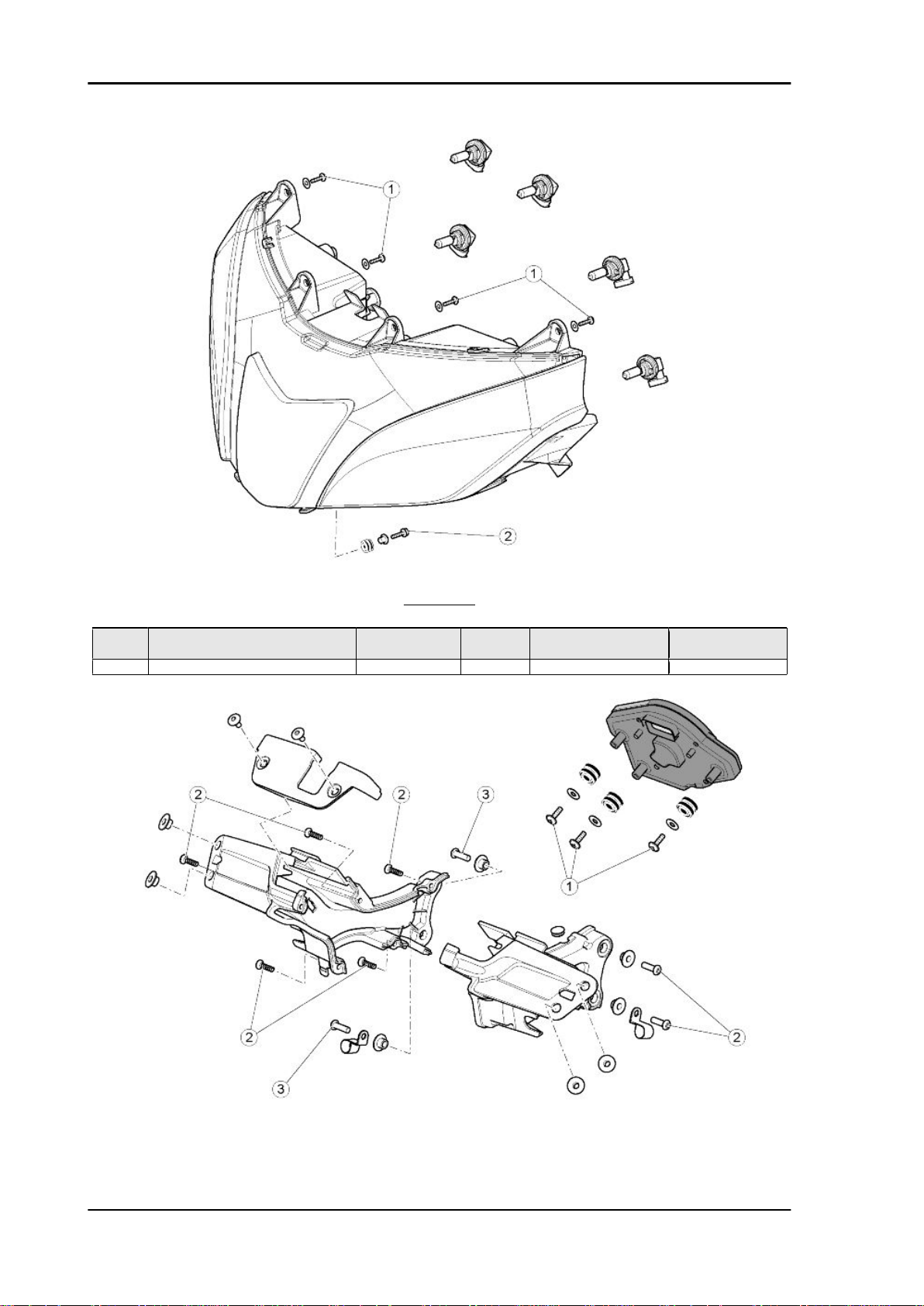
HEADLAMP
pos.
1 Screw fastening headlamp to front
2 Headlamp fixing screw M5 2 + 1 2 Nm (1.47 lbf ft) -
Description Type Quantity Torque Notes
SWP 4.9 4 2 Nm (1.47 lbf ft) -
fairing
CHAR - 20
Page 21
RSV4 Factory Characteristics
INSTRUMENT PANEL
pos. Description Type Quantity Torque Notes
1 Screws fastening the rubber rings to
the instrument panel
2 Instrument panel mounting shell fix-
ing screws
3 Screws fastening instrument panel
mounting to chassis
SWP 4.9 3 3 Nm (2.21 lbf ft) SWP 4.9 5 2 Nm (1.47 lbf ft) -
M6 4 8 Nm (5.9 lbf ft) -
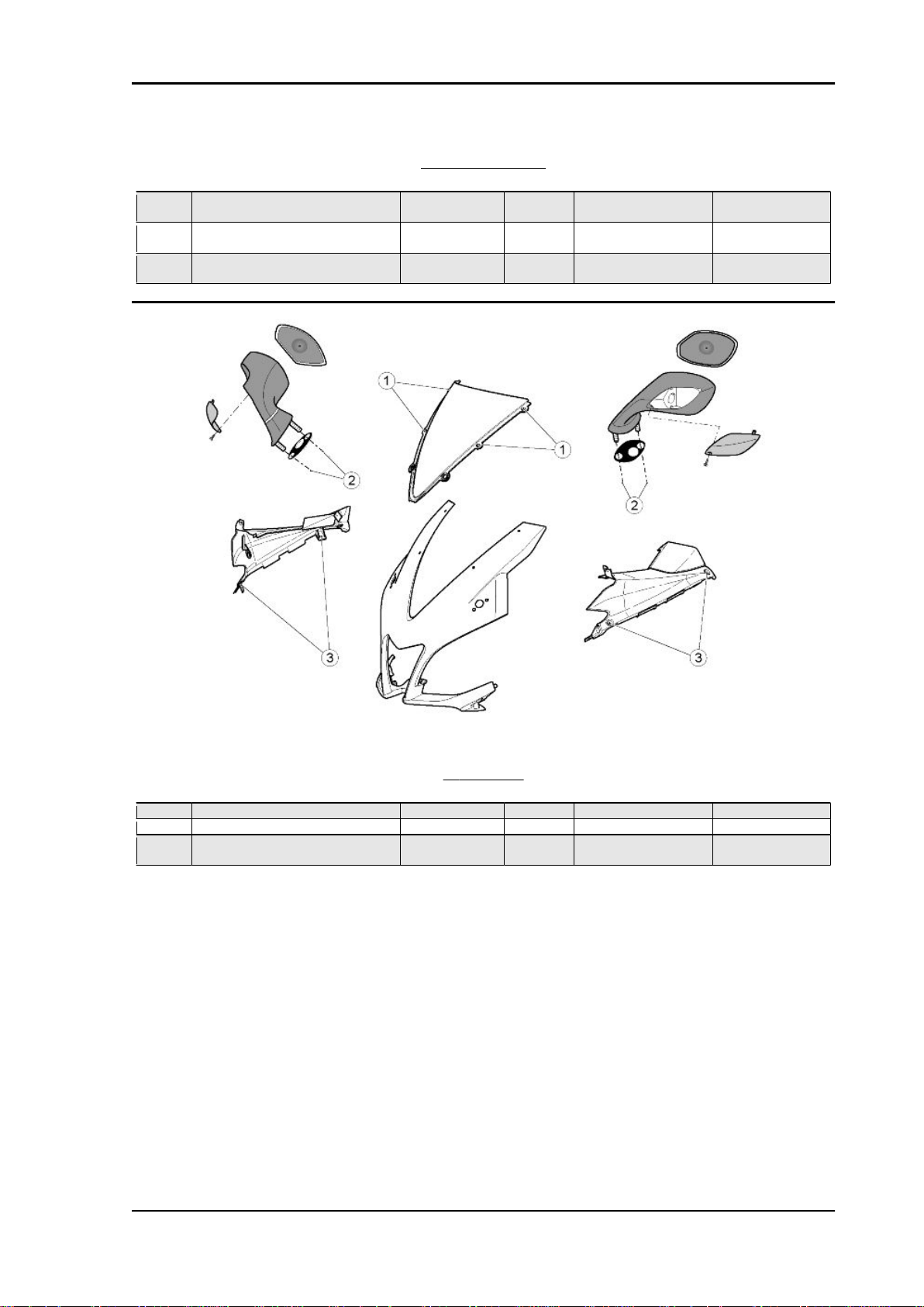
WINDSHIELD
pos.
1 Windshield fixing screws M4 4 0.5 Nm (0.37 lbf ft) 2 Rear-view mirror fixing nuts M6 2 + 2 10 Nm (7.37 lbf ft) 3 - Screws fastening the side fairings
Description Type Quantity Torque Notes
M5 4 1 Nm (0.74 lbf ft) -
to front fairing
CHAR - 21
Page 22
Characteristics RSV4 Factory
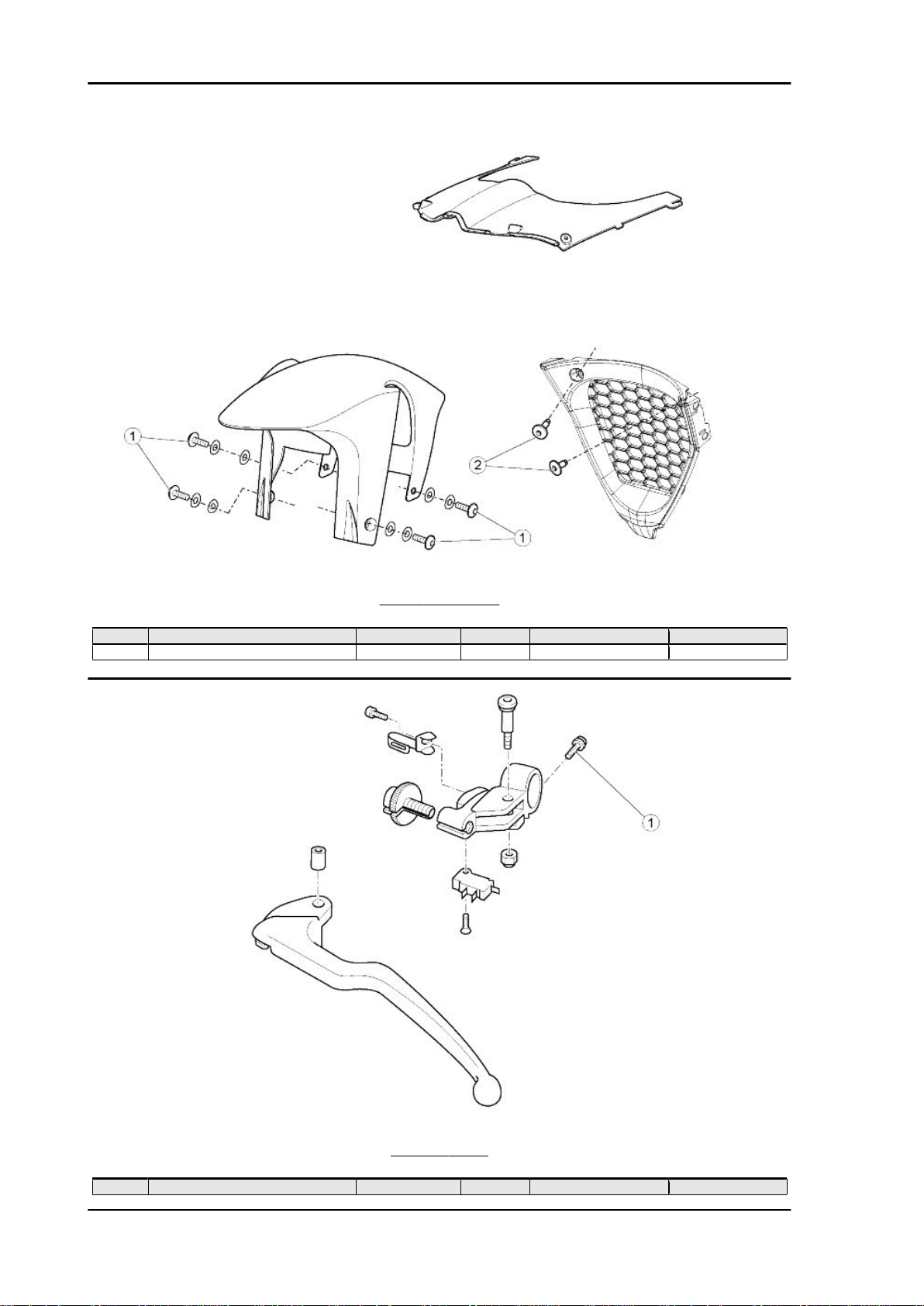
FRONT MUDGUARD
pos.
1 Front mudguard fixing screws M5 4 3 Nm (2.21 lbf ft) 2 Lug fixing screws M5 2 4 Nm (2.95 lbf ft) -
Description Type Quantity Torque Notes
CLUTCH LEVER
pos.
1 Clutch lever collar fixing screws M6 1 10 Nm (7.37 lbf ft) -
CHAR - 22
Description Type Quantity Torque Notes
Page 23
RSV4 Factory Characteristics
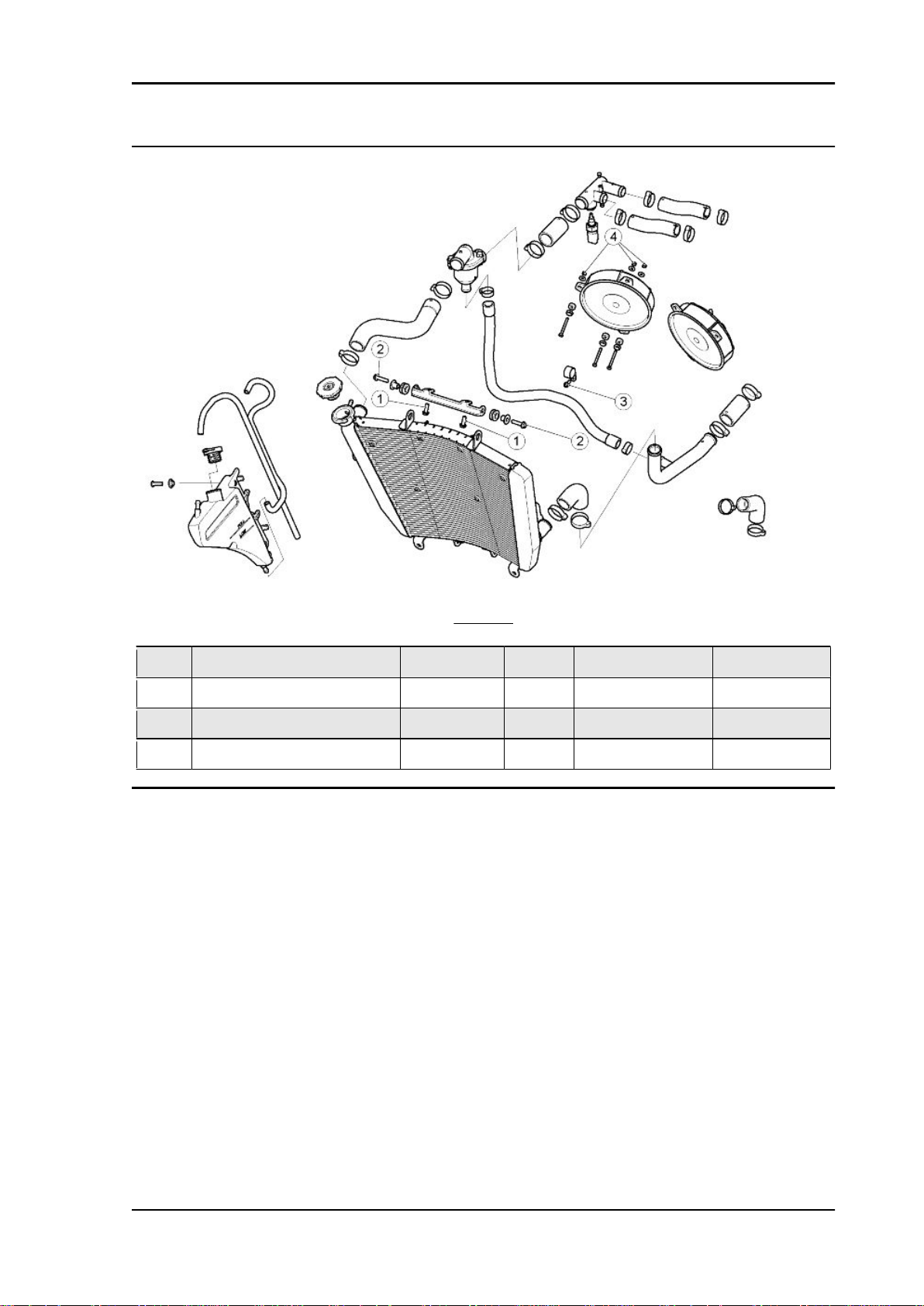
pos.
1 Screws fastening water radiator
2 Screws fastening water radiator to
3 Screw fastening pipe grommet for
4 Screws fastening electric fan to wa-
Description Type Quantity Torque Notes
mounting bracket to chassis
mounting bracket
By-pass water hose
ter radiator
COOLING
M6 2 10 Nm (7.37 lbf ft) M6 2 7 Nm (5.16 lbf ft) M5 1 6 Nm (4.42 lbf ft) M4 6 2 Nm (1.47 lbf ft) -
CHAR - 23
Page 24
Characteristics RSV4 Factory
Central part
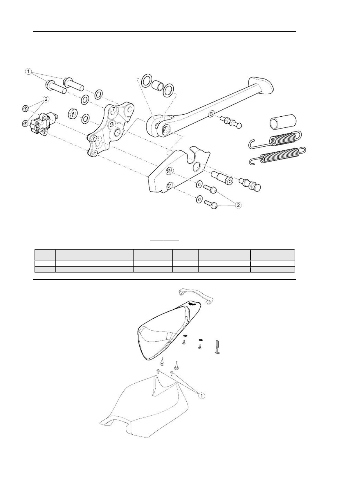
SIDE STAND
pos.
1 Screws fastening the stand to the
2 Linear switch retainer M5 2 4 Nm (2.95 lbf ft) -
- Rear stand bushing fastening screws M6 2 7 Nm (5.16 lbf ft) -
Description Type Quantity Torque Notes
M10 2 45 Nm (33.19 lbf ft) Loct. 243
chassis
CHAR - 24
Page 25
RSV4 Factory Characteristics
SADDLE
pos. Description Type Quantity Torque Notes
1 Rider saddle fixing screw M5 2 6 Nm (4.42 lbf ft) -
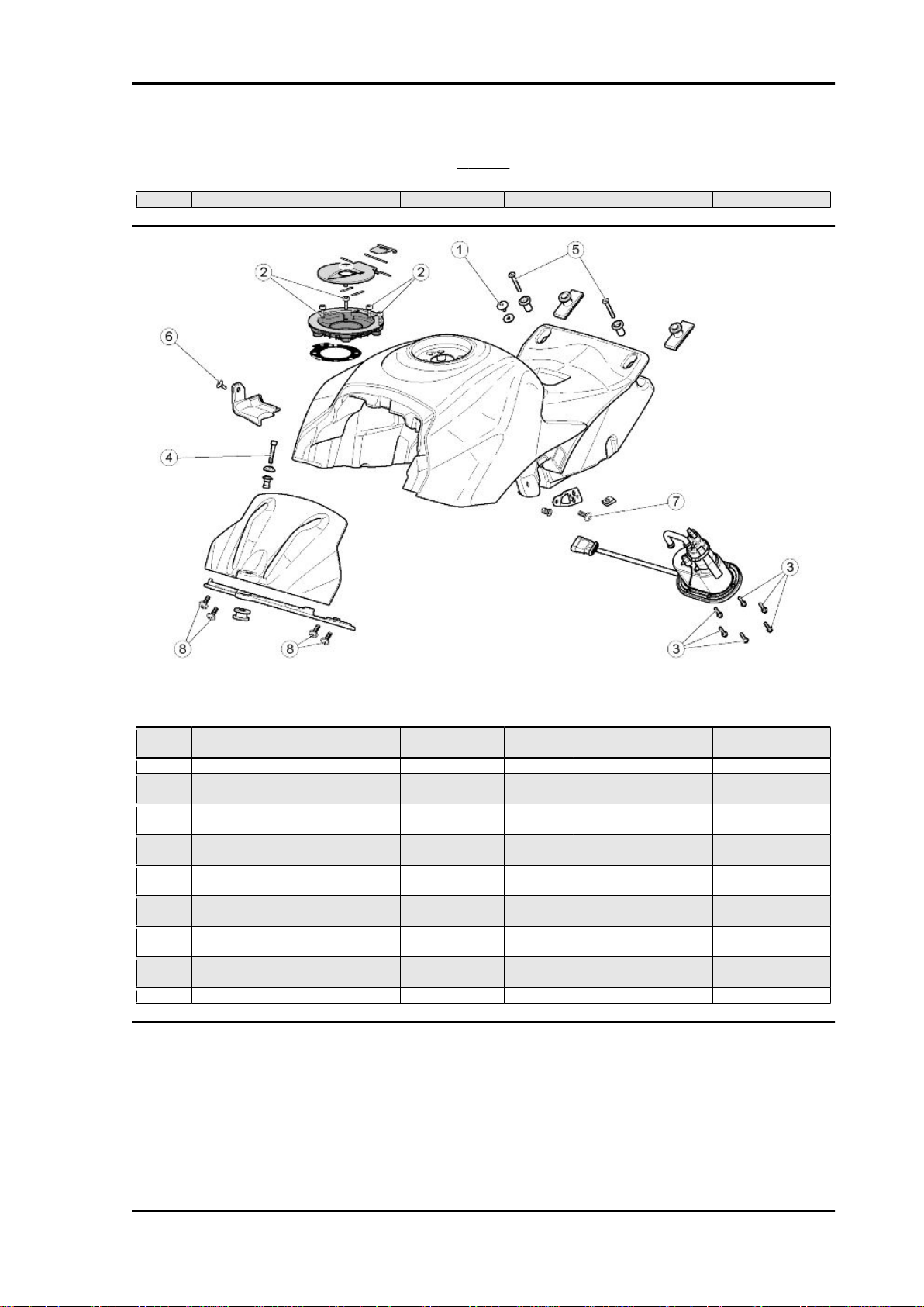
FUEL TANK
pos.
1 Special screw fastening rider saddle
2 Screws fixing the filler to the tank M5 4 4 Nm (2.95 lbf ft) -
3 Screws fixing the fuel pump flange to
4 Front screws fastening the tank to
5 Rear screws fastening the tank to the
6 Screws fastening plastic fuel pipe
7 Left fairing mounting bracket fixing
8 Screws fastening structural tank
- Central screw fastening the cover to
- Fuel tank breather pipe unions M7 2 3 Nm (2.21 lbf ft) -
Description Type Quantity Torque Notes
M6 1 4 Nm (2.95 lbf ft) -
to the tank
M5 8 3 Nm (2.21 lbf ft) -
the tank
M6 1 8 Nm (5.9 lbf ft) -
the chassis
M6 2 7 Nm (5.16 lbf ft) -
rear chassis
M5 1 2.5 Nm (1.84 lbf ft) -
mounting
M5 1 3 Nm (2.21 lbf ft) -
screws
M6 4 3 Nm (2.21 lbf ft) -
mounting to tank
M4 1 0.5 Nm (0.37 lbf ft) -
the tank
CHAR - 25
Page 26

Characteristics RSV4 Factory
FOOTPEGS
pos.
1 Screws fastening rider footpegs to
2 Screws fastening passenger foot-
3 Rider heelrest fixing screws M6 2 + 2 8 Nm (5.9 lbf ft) 4 Passenger heelrest fixing screws M6 2 + 2 8 Nm (5.9 lbf ft) -
- Anti-slip pin M6 1 8 Nm (5.9 lbf ft) -
Description Type Quantity Torques Notes
chassis
pegs to chassis
M8 2 + 2 25 Nm (18.44 lbf ft) M8 2 + 2 18 Nm (13.28 lbf ft) For countries in
which passenger
footpegs are man-
datory or for two
seat configuration
CHAR - 26
Page 27
RSV4 Factory Characteristics
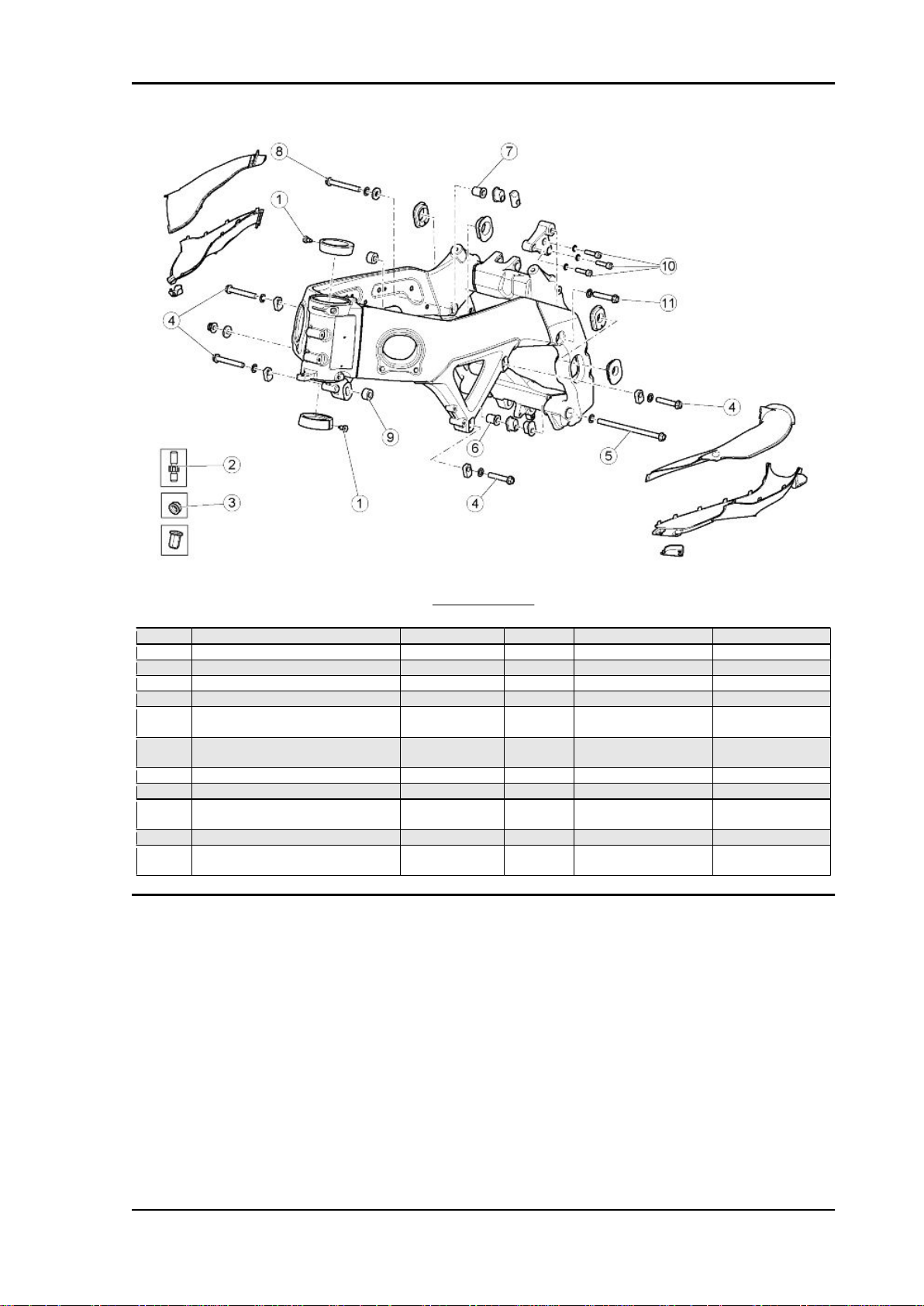
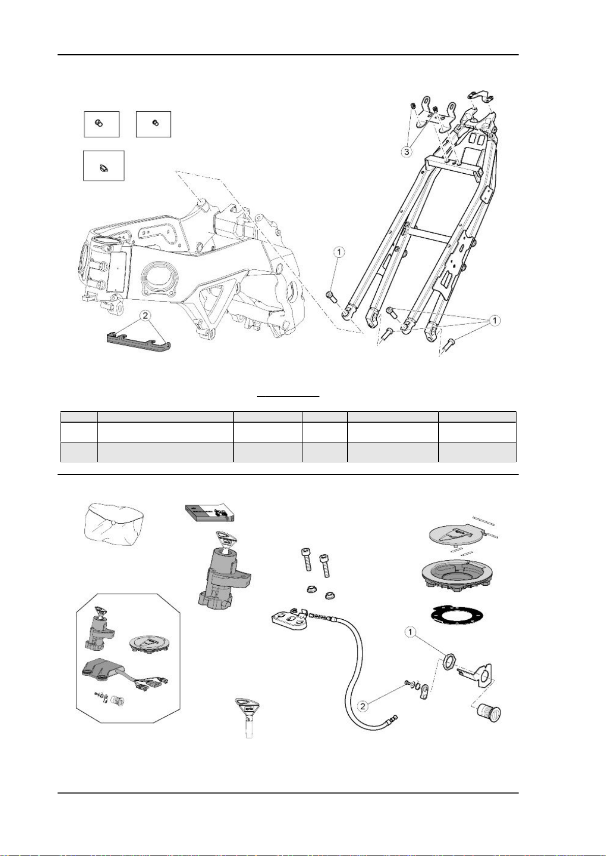
FRONT CHASSIS
pos.
1 Headstock locator dowel M8x1 2 10 Nm (7.37 lbf ft) 2 Threaded inlet duct fastener pins M6 2 + 2 4 Nm (2.95 lbf ft) Loct. 243
3 Inlet duct fixing nuts M6 2 + 2 Manual 4 Front mounts M10 2 + 2 50 Nm (36.88 lbf ft) 5 Lower rear mount M10 1 50 Nm (36.88 lbf ft) 6 Lower rear right hand adjuster screw
7 Upper rear right hand adjuster screw
8 Upper rear right hand mount M10 1 50 Nm (36.88 lbf ft) -
9 Right fairing spacer M6 1 10 Nm (7.37 lbf ft) Loct. 243
10 Upper rear left hand engine mount
11 Upper rear mount M10 1 50 Nm (36.88 lbf ft) -
- Screw fastening the ground cable to
Description Type Quantity Torque Notes
M18x1.5 1 12 Nm (8.85 lbf ft) -
bushing
M18x1.5 1 12 Nm (8.85 lbf ft) -
bushing
M8 3 25 Nm (18.44 lbf ft) -
fastener screws
M6 1 6 Nm (4.42 lbf ft) -
the left side chassis
CHAR - 27
Page 28
Characteristics RSV4 Factory
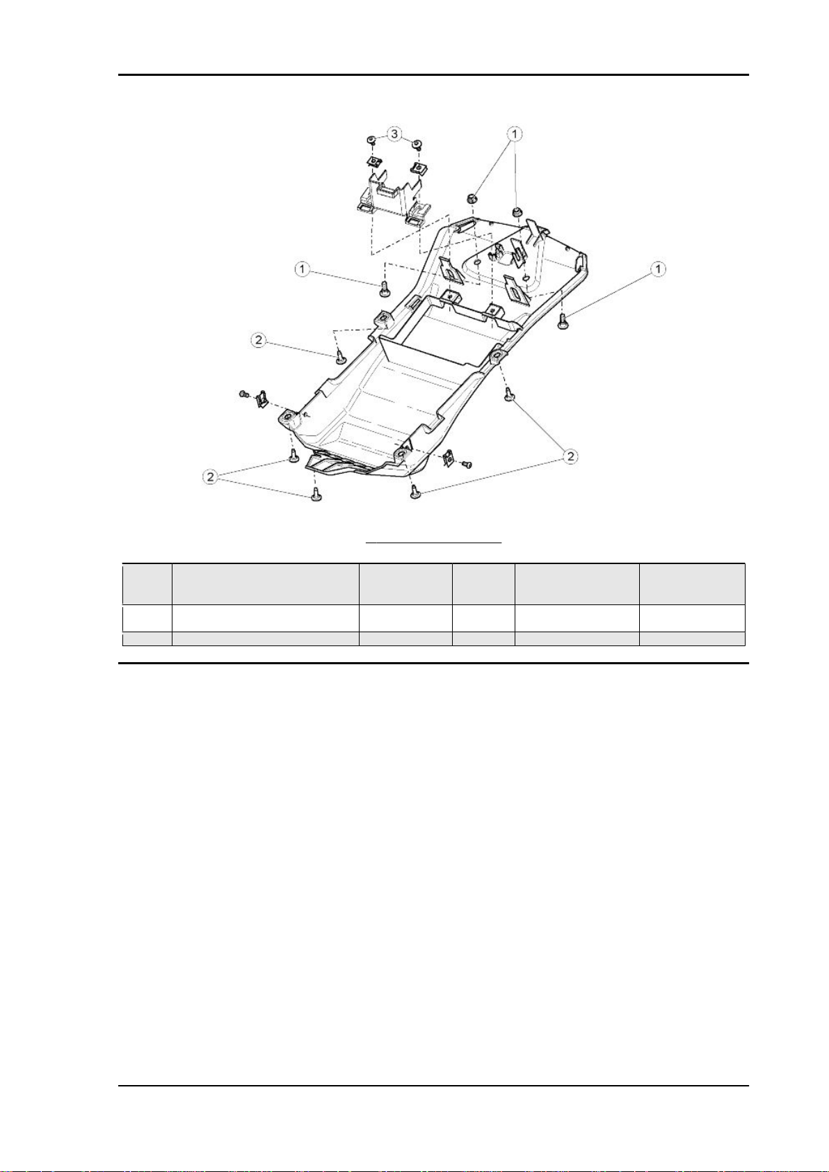
REAR CHASSIS
pos.
1 Saddle mounting fixing screws M10 4 50 Nm (36.88 lbf ft) 2 Screws fastening oil radiator mount-
3 Passenger saddle and saddle cover
Description Type Quantity Torque Notes
M6 2 8 Nm (5.9 lbf ft) -
ing bracket to engine
M6 2 8 Nm (5.9 lbf ft) -
catch plate fixing screws
CHAR - 28
Page 29
RSV4 Factory Characteristics
LOCKS
pos. Description Type Quantity Torque Notes
1 Nut fastening saddle lock to tail fair-
ing
2 Lock lever self-tapping screw M4 1 2 Nm (1.47 lbf ft) -
M22x1.5 1 5 Nm (3.69 lbf ft) -
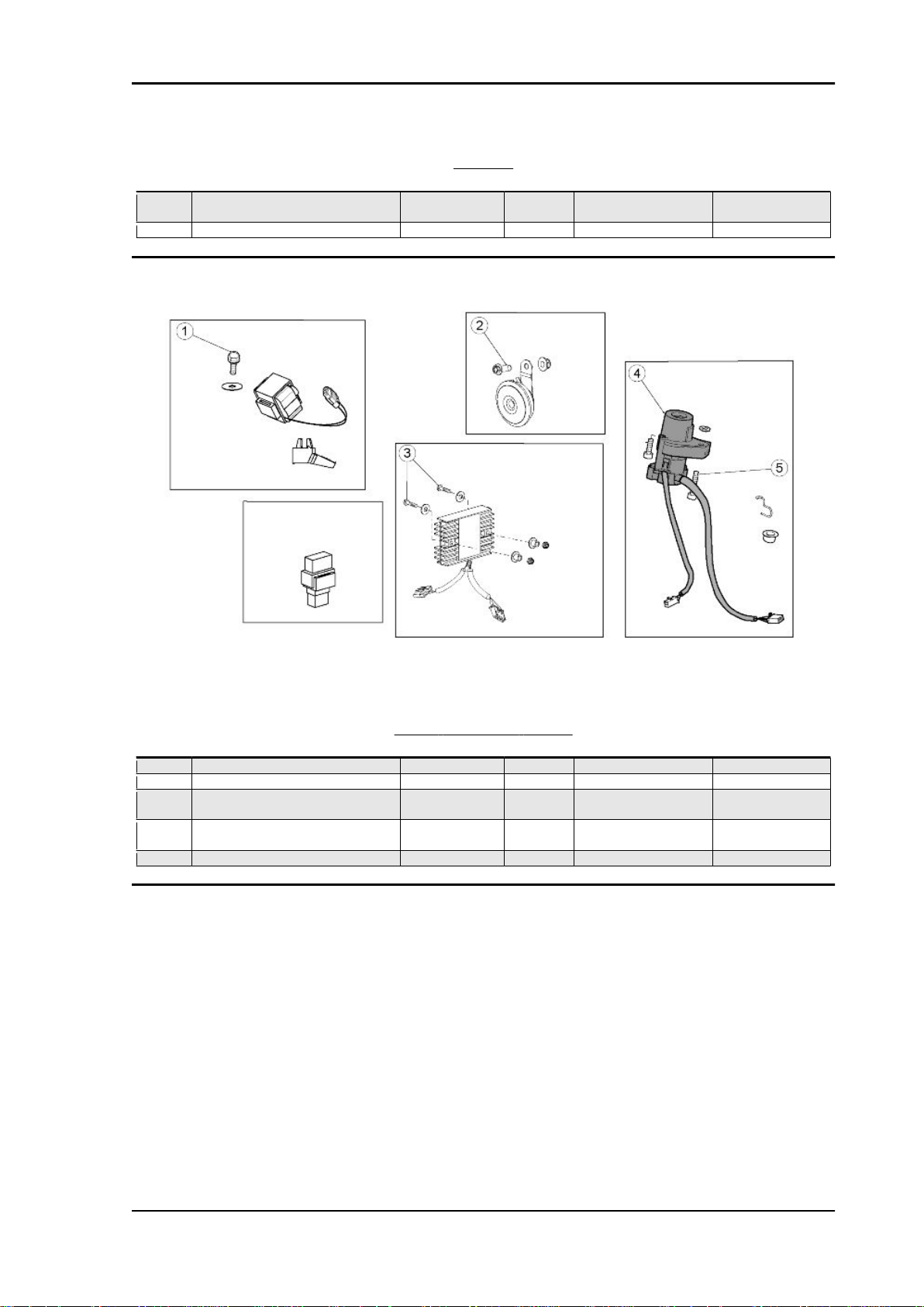
FRONT ELECTRICAL SYSTEM
pos.
1 Fall sensor mounting fixing screw M6 1 8 Nm (5.9 lbf ft) 2 Horn fixing screw M8 1 15 Nm (11.06 lbf ft) 3 Screw fastening the voltage regula-
4 Shear head screw (to the left of the
5 Right hand ignition lock screw M8 1 20 Nm (14.75 lbf ft) -
Description Type Quantity Torque Notes
M6 2 6 Nm (4.42 lbf ft) -
tor to the inner fairing
M8 1 Manual Tighten until the
ignition lock)
head shears off
CHAR - 29
Page 30
Characteristics RSV4 Factory
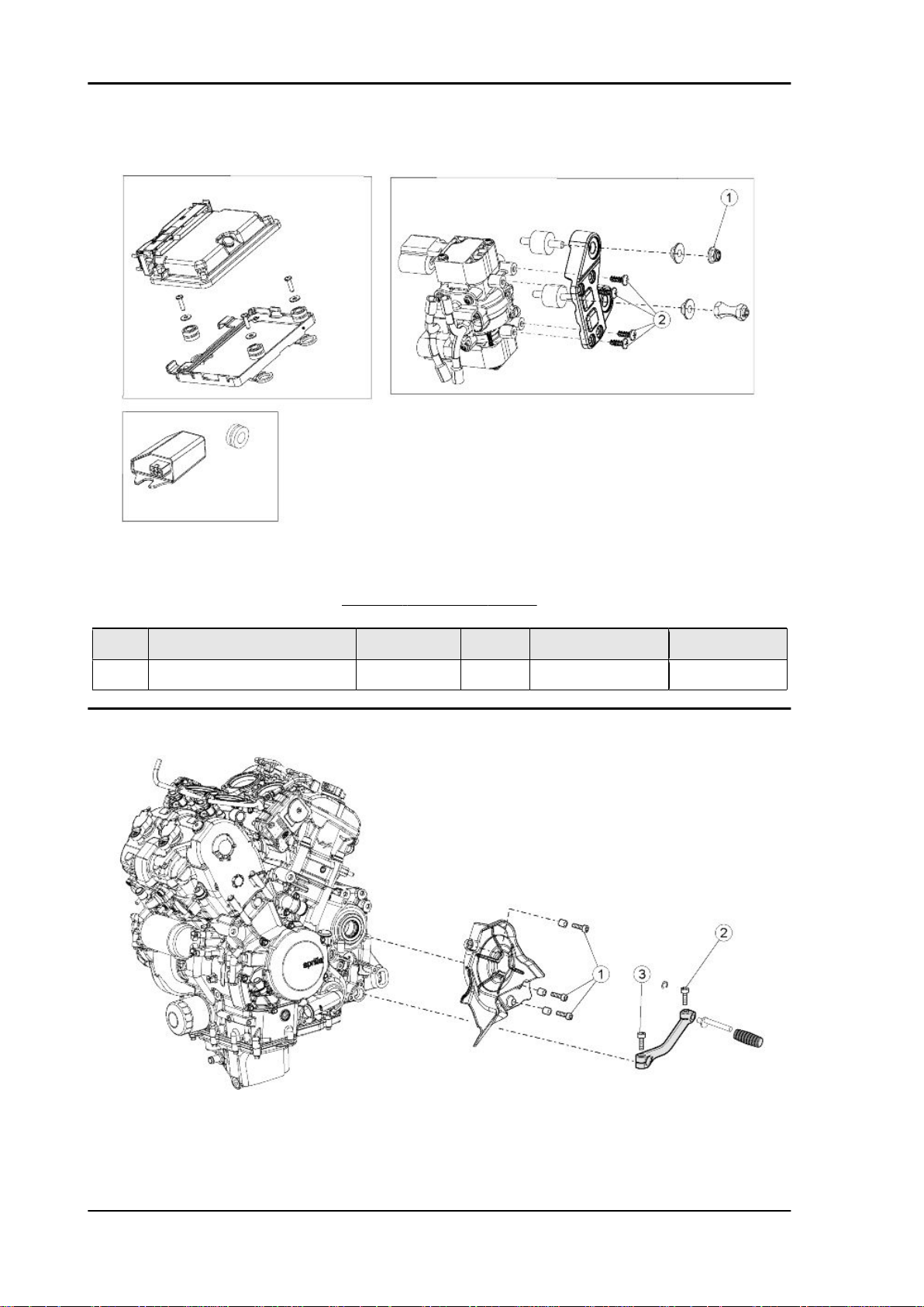
pos.
1 Upper Silentblock nut, demand sen2 Demand sensor fixing screw to
Description Type Quantity Torque Notes
sor mounting bracket
mounting plate
CENTRAL ELECTRICAL SYSTEM
M6 1 5 Nm (3.69 lbf ft) -
SWP 4.9 4 1.2 Nm (0.88 lbf ft) -
CHAR - 30
Page 31

RSV4 Factory Characteristics
ENGINE
pos. Description Type Quantity Torques Notes
1 Pinion protector casing fixing screws M6 3 8 Nm (5.9 lbf ft) 2 Gearbox lever pin fixing screw M6 1 10 Nm (7.37 lbf ft) 3 Gearbox lever fixing screws M6 1 10 Nm (7.37 lbf ft) -
FAIRING
pos.
- Centre screws fastening lower fairing M6 2 10 Nm (7.37 lbf ft) -
- Right hand lower fairing mounting
- Left hand lower fairing mounting
- Screws fixing the side fairings to the
- Screws fixing upper fairing fastener
- Screws fixing upper fairing fastener
- Screws fixing upper fairing fastener
- Screws fixing upper fairing fastener
- Screws fastening the lower fairing to
- Screws fastening the lower fairing to
- Lower fairing lower fastening screws M5 2 2 Nm (1.47 lbf ft) -
- Lower fork fastener fixing screws M6 2 8 Nm (5.90 lbf ft) -
- Screws fixing lower front fairing fas-
- Inner screws fixing fairing to the low-
- Inner screws fastening the fairing to
Description Type Quantity Torque Notes
M6 2 10 Nm (7.37 lbf ft) -
bracket
M6 2 10 Nm (7.37 lbf ft) -
bracket
M5 2 1.5 Nm (1.11 lbf ft) -
side spacers
M5 2 1.5 Nm (1.11 lbf ft) -
to inlet duct
M5 2 1.5 Nm (1.11 lbf ft) -
to front fairing
self-tapping 2 1 Nm (0.74 lbf ft) -
to inlet duct
self-tapping 2 1 Nm (0.74 lbf ft) -
to headlamp
M5 2 + 2 1 Nm (0.74 lbf ft) -
the bracket
M5 2 2 Nm (1.47 lbf ft) -
the lug
SWP 3.9 2 1 Nm (0.74 lbf ft) -
tener to inlet ducts
M4 2 0.5 Nm (0.37 lbf ft) -
er front fairing fastener
M5 2 2 Nm (1.47 lbf ft) -
the lug
CHAR - 31
Page 32

Characteristics RSV4 Factory
Back side
EXHAUST
pos.
1 Exhaust manifold flange fixing nuts M7 8 13 Nm (9.59 lbf ft) 2 Silencer clamp fixing screw M6 1 10 Nm (7.37 lbf ft) 3 Screw fastening silencer to right
4 Screw fastening silencer to central
5 Cosmetic silencer shield fixing screw M5 2 5 Nm (3.69 lbf ft) -
6 Oxygen sensor fastener M18x1.5 1 38 Nm (28.03 lbf ft) 7 Fastener screw for cable grommet
for exhaust butterfly valve cables
8 Exhaust butterfly valve actuator fix-
Description Type Quantity Torque Notes
M8 1 25 Nm (18.44 lbf ft) -
hand footpeg mounting
M8 1 20 Nm (14.75 lbf ft) -
lower fairing bracket
M6 1 10 Nm (7.37 lbf ft) M6 2 10 Nm (7.37 lbf ft) -
ing screws
CHAR - 32
Page 33

RSV4 Factory Characteristics
REAR WHEEL
pos.
1 Rear wheel spindle nut M25x1.5 1 120 Nm (88.5 lbf ft) 2 Screws fastening sprocket on
Description Type Quantity Torque Notes
M10 5 50 Nm (36.88 lbf ft) -
sprocket mount
CHAR - 33
Page 34

Characteristics RSV4 Factory
REAR BRAKE PUMP
pos. Description Type Quantity Torque Notes
1 Rear brake rod lock nut M6 1 12 Nm (8.85 lbf ft) 2 Rear brake pump fixing screws M6 2 8 Nm (5.9 lbf ft) 3 Rear brake lever fixing screw M8 1 25 Nm (18.44 lbf ft) -
REAR BRAKE CALLIPER
pos.
1 Rear brake disc fixing screws M8 5 30 Nm (22.13 lbf ft) Loct. 243
2 Screw fastening odometer sensor
onto rear brake calliper mounting
3 Rear brake calliper mounting plate
4 Rear calliper fixing screw M5 2 25 Nm (18.44 lbf ft) -
5 Brake pipe clamp fixing screw M5 2 4 Nm (2.95 lbf ft) -
- Brake pipe bracket fixing screw M5 2 4 Nm (2.95 lbf ft) -
Description Type Quantity Torque Notes
M6 1 12 Nm (8.85 lbf ft) -
M12 1 50 Nm (36.88 lbf ft) Loct. 243
lock pin
CHAR - 34
Page 35

RSV4 Factory Characteristics
REAR FORK
pos.
1 Swingarm adjuster screw bushing M30x1.5 1 12 Nm (8.85 lbf ft) 2 Swingarm ring nut M30x1.5 1 60 Nm (44.25 lbf ft) 3 Swingarm pin nut M20x1.5 1 65 Nm (47.94 lbf ft) AGIP GREASE
4 Chain casing fixing screws M5 2 4 Nm (2.95 lbf ft) 5 Front chain guide fixing screw M5 1 4 Nm (2.95 lbf ft) 6 Rear chain guide fixing nut M6 1 7 Nm (5.16 lbf ft) 7 Chain skid fixing screws M5 2 2 Nm (1.47 lbf ft) -
- Lower chain skid fixing screws M6 2 10 Nm (7.37 lbf ft) -
- Chain guide fixing screw M6 1 8 Nm (5.90 lbf ft) -
Description Type Quantity Torque Notes
SM2
CHAR - 35
Page 36

Characteristics RSV4 Factory
REAR SHOCK ABSORBER
pos.
1 Upper shock absorber fixing screw M10 1 50 Nm (36.88 lbf ft) 2 Dual linkage fixing screw M10 3 50 Nm (36.88 lbf ft) 3 Screw fastening single linkage to
Description Type Quantity Torque Notes
M10 1 50 Nm (36.88 lbf ft) -
chassis
CHAR - 36
Page 37
RSV4 Factory Characteristics
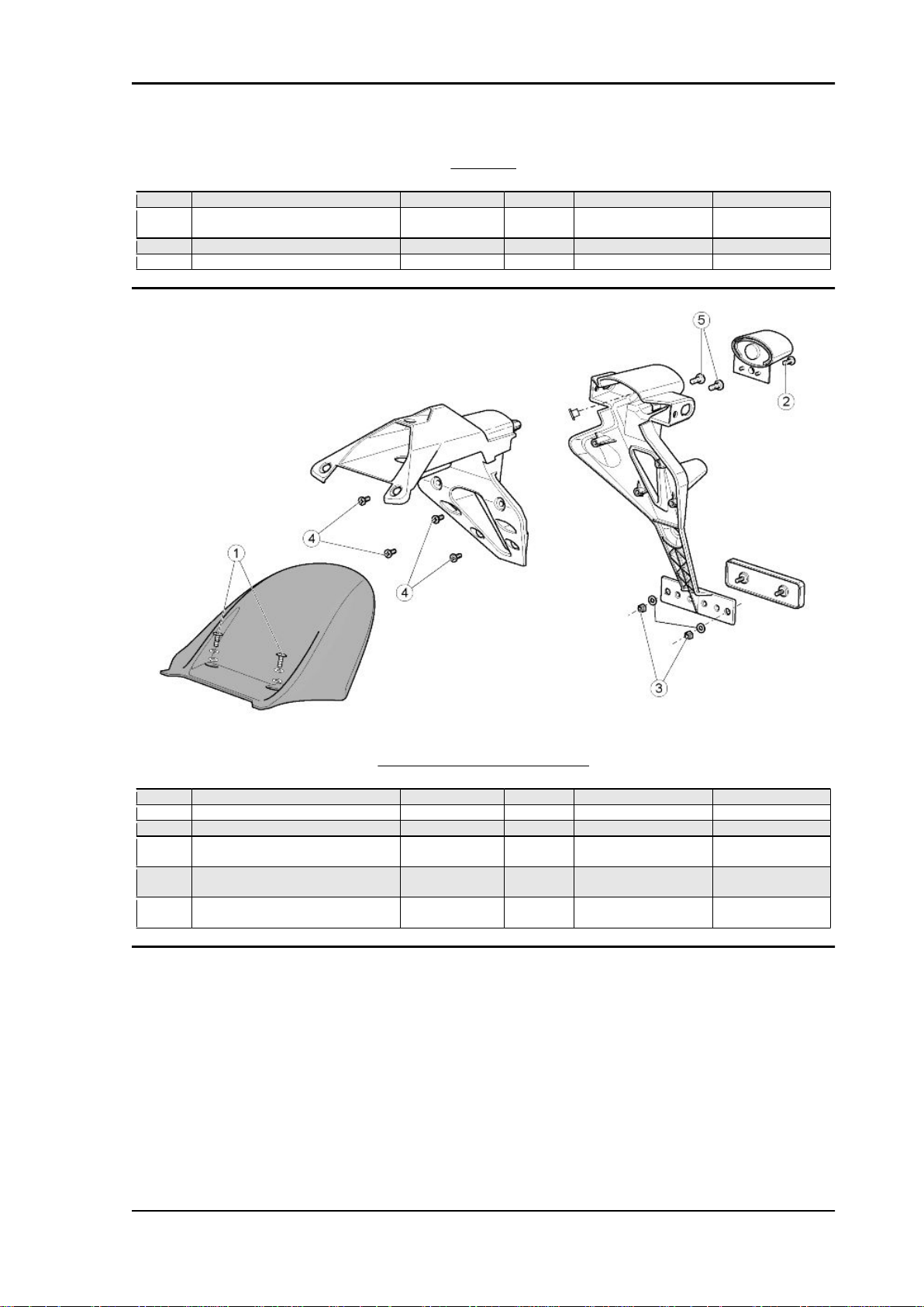
TAILLIGHT
pos. Description Type Quantity Torque Notes
1 Taillight fixing screws M5 2 3 Nm (2.21 lbf ft) 2 Taillight mounting bracket fixing
screws
3 Rear turn indicator fixing screws M6 2 2.5 Nm (1.84 lbf ft) 4 Taillight cover fixing screws SWP 2.9 1 0.5 Nm (0.37 lbf ft) -
M5 2 4 Nm (2.95 lbf ft) -
LICENSE PLATE HOLDER
pos.
1 Rear mudguard fixing screws M6 2 3 Nm (2.21 lbf ft) 2 License plate light fixing screws M4 1 1 Nm (0.74 lbf ft) 3 Reflector fixing nuts M4 2 1 Nm (0.74 lbf ft) 4 Screws fastening rear license plate
holder to front license plate holder
5 Screws fastening rear license plate
holder to front license plate holder
- Screws fastening license plate
mounting to saddle mounting casting
Description Type Quantity Torque Notes
SWP 3.9 4 1 Nm (0.74 lbf ft) SWP 4.9 2 2 Nm (1.47 lbf ft) -
M6 3 4 Nm (2.95 lbf ft) -
CHAR - 37
Page 38

Characteristics RSV4 Factory
TAIL
pos.
1 Rear screws fastening tail fairing to
2 Screws fastening the saddle cover
3 Saddle cover pin fixing screws M4 1 1.5 Nm (1.11 lbf ft) -
4 Screws fastening grilles to tail fairing M5 2 0.5 Nm (0.37 lbf ft) 5 Screws fastening side fairings to tail
6 Screws fixing side fairings to tank M5 2 + 2 2 Nm (1.47 lbf ft) 7 Screws fastening tail fairing to saddle
8 Screws fastening tail fairing to saddle
9 Screws fixing tail fairing to lower sad-
Description Type Quantity Torque Notes
M5 2 3 Nm (2.21 lbf ft) -
taillight bracket
SWP 2.9 3 1 Nm (0.74 lbf ft) -
base to the saddle cover
M5 2 1 Nm (0.74 lbf ft) -
fairing
M5 2 3 Nm (2.21 lbf ft) -
mounting
M5 2 2 Nm (1.47 lbf ft) -
mounting bracket
M5 2 3 Nm (2.21 lbf ft) -
dle mounting fastener
CHAR - 38
Page 39
RSV4 Factory Characteristics
HELMET COMPARTMENT
pos.
1 Screws and nuts for fastening li-
cense plate holder to saddle mount2 Lower saddle mounting fastener fix3 Battery bracket fixing screws M5 2 2 Nm (1.47 lbf ft) -
Description Type Quantity Torque Notes
M6 2 4 Nm (2.95 lbf ft) -
ing plate
M5 5 3 Nm (2.21 lbf ft) -
ing screws
CHAR - 39
Page 40

Characteristics RSV4 Factory
Engine
CLUTCH COVER
pos.
1 Rpm sensor fixing screw - 1 8 Nm (5.9 lbf ft) 2 TE flanged screw M6x20 1 12 Nm (8.85 lbf ft) 3 TE flanged screws M6x35 2 12 Nm (8.85 lbf ft) 4 TE flanged screws M6x22 16 12 Nm (8.85 lbf ft) 5 Engine timing inspection cap - 1 25 Nm (18.44 lbf ft) -
CHAR - 40
Description Type Quantity Torque Notes
Page 41

RSV4 Factory Characteristics
VALVE COVER
pos.
1 Head cover fixing screws - 6 10 Nm (7.37 lbf ft) 2 Coil fixing screws - 4 8 Nm (5.9 lbf ft) Loct. 243
3 Spark plugs - 4 12 Nm (8.85 lbf ft) -
Description Type Quantity Torque Notes
CHAR - 41
Page 42

Characteristics RSV4 Factory
CYLINDERS - PISTON
pos. Description Type Quantity Torque Notes
1 Screws fastening water union onto
crankcase
M6x40 2 10 Nm (7.37 lbf ft) -
HEADS
pos.
1 Exhaust stud bolts - 8 10 Nm (7.37 lbf ft) 2 Camshaft cam tower fixing screws M6x45 20 12 Nm (8.85 lbf ft) 3 Reed valve cover fixing screws - 6 6 Nm (4.42 lbf ft) 4 Water outlet union fixing screw - 2 12 Nm (8.85 lbf ft) Loct. 243
5 Flanged head nut - 12 30 + 55 Nm (22.13 +
6 Head fastener screw, chain side M6x55 4 12 Nm (8.85 lbf ft) -
Description Type Quantity Torque Notes
40.56 lbf ft)
Molykote spray on
thread and under
head
CHAR - 42
Page 43

RSV4 Factory Characteristics
TIMING SYSTEM
pos.
1 Screws fastening the timing system
2 Skid fastener screws M8 2 20 Nm (14.75 lbf ft) Loct. 243
3 Skid fastener screws M6x18 2 10 Nm (7.37 lbf ft) Loct. 243
Description Type Quantity Torque Notes
M8 4 30 Nm (22.13 lbf ft) Loct. 243
gear on the intake shaft
CHAR - 43
Page 44

Characteristics RSV4 Factory
CRANKSHAFT
pos.
1 Connecting rod screws - 8 15 Nm (11.06 lbf ft) +
2 Fastener ring nut for alternator side
3 Primary sprocket fixing ring nut - 1 200 Nm (147.51 lbf ft) Loct. 243
4 Alternator fixing screw M12x1.25 1 120 Nm (88.51 lbf ft) 5 Tone wheel fixing screw M8x1.25 1 30 Nm (22.13 lbf ft) Loct. 3M or 270
Description Type Quantity Torque Notes
40° + 60°
- 1 100 Nm (73.76 lbf ft) Loct. 243
timing sprocket
Lubricate the thread
and under the head
with Molykote
CHAR - 44
Page 45

RSV4 Factory Characteristics
CRANKCASES
pos.
1 Head stud bolts - 12 20 Nm (14.75 lbf ft) Loct. 648 or 270
2 Special screw for piston cooling oil jet - 4 6 Nm (4.42 lbf ft) Loct. 2045
3 Crankcase stud bolts - 6 20 Nm (14.75 lbf ft) Loct. 648 or 270
4 Main crank flanged nut - 6 30 + 55 Nm (22.13 +
5 Crankcase fixing screw M8x70 4 25 Nm (18.44 lbf ft) Lubricate the thread
6 Crankcase fixing screw M8x35 3 25 Nm (18.44 lbf ft) Lubricate the thread
7 Crankcase fixing screw M6x45 2 10 Nm (7.37 lbf ft) Lubricate the thread
8 Crankcase fixing screw M6x20 5 10 Nm (7.37 lbf ft) Lubricate the thread
9 Crankcase fixing screw M6x20 5 10 Nm (7.37 lbf ft) Lubricate the thread
Description Type Quantity Torque Notes
40.57 lbf ft)
Molykote - lubricate
the thread and un-
der the head
and under the head
and under the head
and under the head
and under the head
and under the head
CHAR - 45
Page 46

Characteristics RSV4 Factory
GEARBOX
pos.
1 Connector drum fastener screw M6x20 1 10 Nm (7.37 lbf ft) Loct. 243
2 Bearing retainer plate fixing screw M6x16 3 10 Nm (7.37 lbf ft) Loct. 243
3 Flange fixing screws M8x25 6 25 Nm (18.44 lbf ft) 4 Index lever fixing screw M6 1 10 Nm (7.37 lbf ft) Loct. 243
5 Pinion retainer - 1 50 Nm (36.88 lbf ft) Loct. 243
6 Screw retaining pre-selector on
- Gear indicator fixing screw M5x15 2 6 Nm (4.42 lbf ft) -
Description Type Quantity Torque Notes
- 1 25 Nm (18.44 lbf ft) Loct. 270
crankcase
CHAR - 46
Page 47

RSV4 Factory Characteristics
CLUTCH
pos. Description Type Quantity Torque Notes
1 Clutch nut - 1 150 Nm (110.63 lbf ft) Loct. 243
pos.
1 Hex headed nut, cl.10 type 2 ISO
Description Type Quantity Torque Notes
8674
IGNITION UNIT
M10x1 1 50 Nm (36.88 lbf ft) Loct. 243
CHAR - 47
Page 48
Characteristics RSV4 Factory
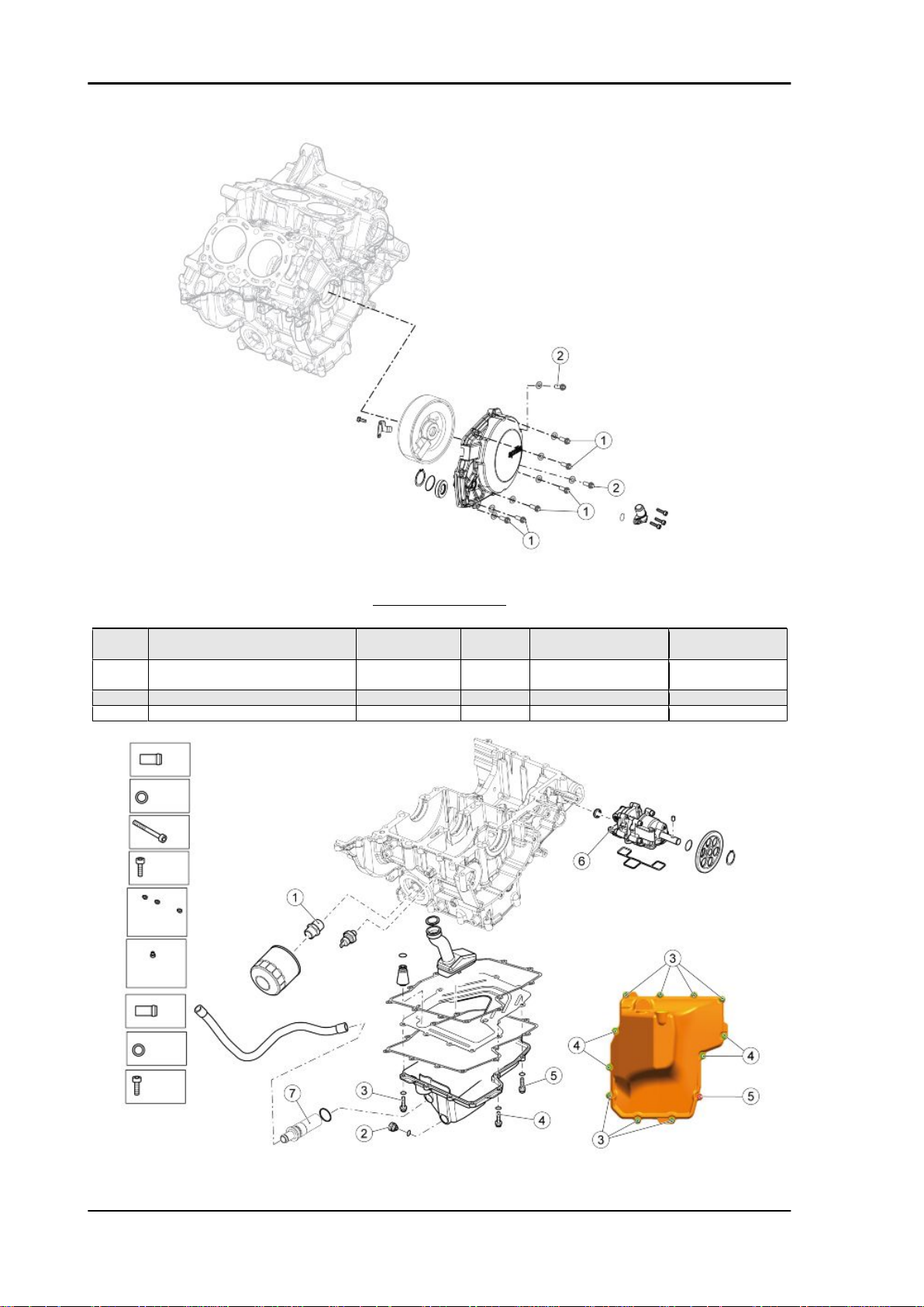
ALTERNATOR COVER
pos.
1 Screws fastening cover onto centre
2 Cover fastener screws, alternator
- Stator fixing screw UNI 5931 CL8.8 M6x25 3 10 Nm (7.37 lbf ft) Loct. 243
- Flanged screw M5x12 1 6 Nm (4.42 lbf ft) Loct. 243
Description Type Quantity Torque Notes
M6x25 6 12 Nm (8.85 lbf ft) -
pins
M6x40 2 12 Nm (8.85 lbf ft) -
side
CHAR - 48
Page 49

RSV4 Factory Characteristics
LUBRICATION
pos. Description Type Quantity Torque Notes
1 Oil filter union fixing screw - 1 30 Nm (22.13 lbf ft) 2 Oil drainage plug - 1 30 Nm (22.12 lbf ft) 3 Oil sump fixing screws M6x30 7 12 Nm (8.85 lbf ft) 4 Oil sump fixing screws M6x22 4 12 Nm (8.85 lbf ft) 5 Oil sump fixing screws M6x25 1 12 Nm (8.85 lbf ft) 6 Screws fastening the pump to the
crankcase
7 Oil pipe union fixing screw M6 1 8 Nm (5.90 lbf ft) Loct. 243
- Screw fastening the diffuser in the oil
sump
M6 5+1 10 Nm (7.37 lbf ft) -
- 1 10 Nm (7.37 lbf ft) -
pos.
1 Secondary air system solenoid
Description Type Quantity Torque Notes
screws
SECONDARY AIR SYSTEM
- 2 10 Nm (7.37 lbf ft) -
CHAR - 49
Page 50

Characteristics RSV4 Factory
WATER PUMP
pos.
1 Screws fastening the pump to the
Description Type Quantity Torque Notes
M6x25 2 10 Nm (7.37 lbf ft) -
crankcase
Recommended products chart
RECOMMENDED PRODUCTS
Product
AGIP TEC 4T, SAE 15W-50 Engine oil Use branded oils with performance
AGIP MP GREASE Grease for bearings, joints, couplings
AGIP PERMANENT SPEZIAL Coolant Ready for use mixed biodegradable cool-
AGIP BRAKE 4 Brake fluid As an alternative to the recommended
ÖHLINS 5W Fork oil -
Description Specifications
equivalent to or exceeding CCMC G-4
A.P.I. SG. SAE 15W-50 specifications
and linkages
As an alternative to the recommended
product, use top branded grease for roller
bearings with an operating temperature
range of -30°C to +140°C (-22°F to +284°
F), a drop point between 150°C and 230°
C (302°F and 446°F), high corrosion protection qualities and good water and rust
resistance.
ant with "long life" technology and characteristics (red). Freezing protection up to
-40°C. Compliant with CUNA 956-16
standard.
fluid, other fluids that meet or exceed the
required specifications may be used.
SAE J1703, NHTSA 116 DOT 4, ISO
4925 Synthetic fluid
CHAR - 50
Page 51

INDEX OF TOPICS
SPECIAL TOOLS S-TOOLS
Page 52

Special tools RSV4 Factory
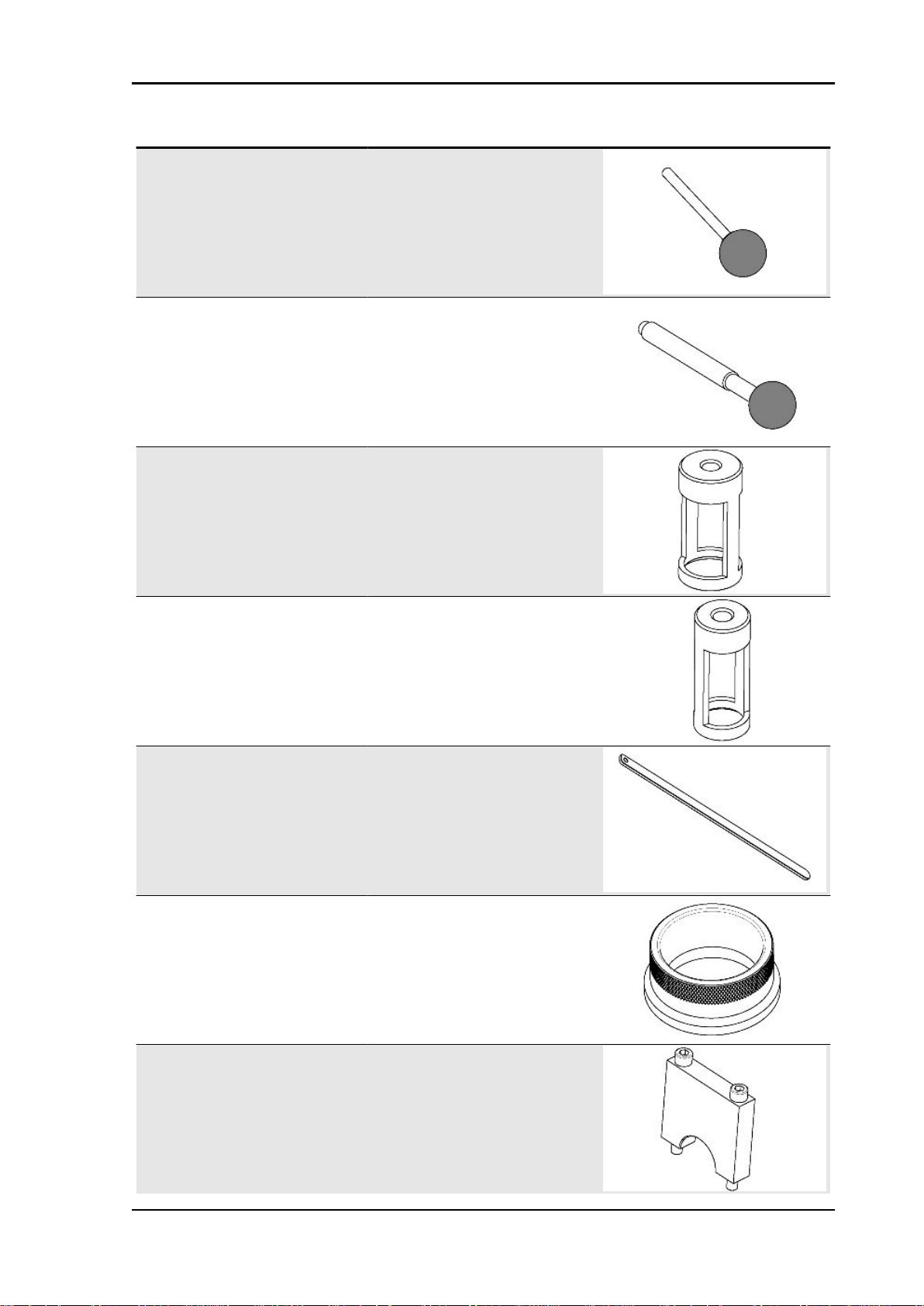
SPECIAL TOOLS
Stores code Description
020845Y Engine support
020846Y Retaining tray + plastic caps
020847Y Flywheel extractor
020848Y Flywheel retainer
020849Y Clutch retainer
020850Y Primary gear lock
S-TOOLS - 52
Page 53
RSV4 Factory Special tools
Stores code Description
020851Y Camshaft timing pin
020852Y Crankshaft timing pin
020853Y Intake valve spring compressor
020854Y Outlet valve spring compressor
020855Y Lever for engaging the chain tensioner
020856Y Piston installation ring
020857Y Crankshaft bearing U bolt
S-TOOLS - 53
Page 54
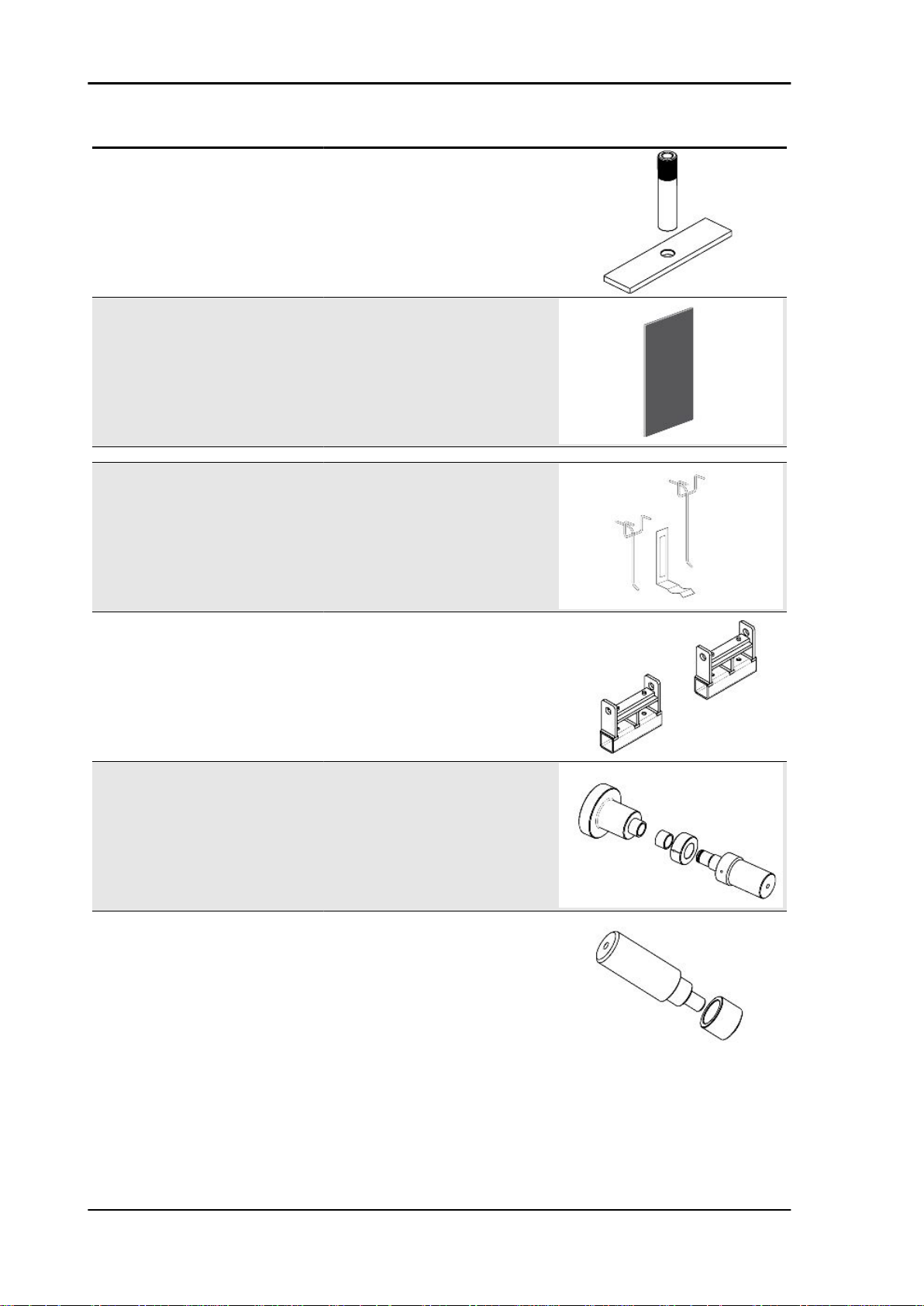
Special tools RSV4 Factory
Stores code Description
020858Y Device for holding the pistons in the cyl-
AP8140199 Tool panel
020859Y Panel graphics
8140426 Hooks for panel
inders
020860Y Engine support extension
020861Y Countershaft bushing punch
020862Y Gearbox control rod roller cage fitting
punch
S-TOOLS - 54
Page 55

RSV4 Factory Special tools
Stores code Description
020863Y Desmodromic drum roller cage fitting
020864Y Engine mounting plate
020865Y Support for camshaft gear on head
punch
020709Y Engine support
AP8140187 Engine support stand
020376Y Adapter handle
020363Y 20-mm Oil seal guide
S-TOOLS - 55
Page 56

Special tools RSV4 Factory
Stores code Description
020364Y 25-mm Guide
020359Y 42 x 47 mm punch
020360Y 52x55 mm Adaptor
020655Y 62x68 mm Adaptor
020408Y 72x75-mm (2.83x2.95 in) adaptor
020306Y Punch for fitting the valve seal rings
S-TOOLS - 56
Page 57
RSV4 Factory Special tools
Stores code Description
020431Y Valve oil seal extractor
AP8140180 Extractor for bushings
AP8140179 Valve spring compressor
0277308 Guide bushing for secondary gearbox
AP8140146 Weight
AP8140189 Oil seal fitting tool for Ø 43 mm (1.69 in)
shaft
orifices
S-TOOLS - 57
Page 58

Special tools RSV4 Factory
Stores code Description
AP8140181 Fuel pressure checking tool
020481Y Control unit interface wiring
020680Y TXB Navigator
S-TOOLS - 58
Page 59

INDEX OF TOPICS
MAINTENANCE MAIN
Page 60

Maintenance RSV4 Factory
Maintenance chart
Correct maintenance is fundamental for ensuring the longevity of your vehicle and maintaining optimum
functionality and performance.
For this purpose, aprilia has formulated a series of checks and scheduled services (at the owner's
expense), are summarised in the table given in the following page. We recommend having any minor
faults resolved immediately by an Authorised aprilia Dealer, without waiting until the next scheduled
service interval.
All scheduled services must be carried out at the specified intervals and mileage, as soon as the predetermined mileage is reached. Carrying out scheduled services on time is essential for the validity of
your warranty. For further information regarding Warranty procedures and ''Scheduled Maintenance'',
please refer to the ''Warranty Booklet''.
NOTE
CARRY OUT MAINTENANCE OPERATIONS AT HALF THE INTERVALS SPECIFIED IF THE VEHICLE IS USED IN PARTICULAR RAINY OR DUSTY CONDITIONS, OFF ROAD OR FOR TRACK
USE.
I: INSPECT AND CLEAN, ADJUST, LUBRICATE OR REPLACE IF NECESSARY
C: CLEAN, R: REPLACE, A: ADJUST, L: LUBRICATE
(1) Check at each engine start
(2) Check and clean and adjust or replace, if necessary, before every journey.
(3) Check and clean and adjust or replace, if necessary, every 1000 Km (621 mi)
(4) Replace every 2 years
(5) Replace every 4 years
(6) Every 5000 Km (3107 mi) if the vehicle is used for racing
(7) Every 10000 Km (6213 mi) if the vehicle is used for racing
ROUTINE MAINTENANCE TABLE
Km x 1000
Rear shock absorber (6) I I
Set up (6) I I I I I
Cylinder equalisation I I I I
Spark plug (6) I R I R
Drive chain (3) I - L I - L I - L I - L I - L
Clutch cable L L L L L
Control cables and controls (6) I I I I I
Sprocket - pinion (6) I I I I
Rear suspension bearings - linkages I I
Steering bearings and steering free play (6) I I I I
Wheel bearings (6) I I I I
Control unit diagnosis I I I I
Brake discs (6) I I I I I
Air filter (6) I R I R
Engine oil filter (6) R R R R R
Engine oil filter (on pickup screen) (6) C
Fork I I
General vehicle operation (6) I I I I I
Valve clearance (7) A A
Cooling system (6) I I I I
1 10 20 30 40
MAIN - 60
Page 61

RSV4 Factory Maintenance
Km x 1000 1 10 20 30 40
Brake systems (6) I I I I I
Light circuit I I I I I
Stand switch I I I I
Safety switches I I I I I
Stop switches I I I I
Brake fluid (4) I I I I I
Coolant (4) I I I I I
Fork oil (7) R R
Engine oil (6) R R R R R
Light alignment I I I I
Fork oil baffles (6) I R I R
Flexible coupling I I
Tyres - pressure/wear (2) I I I I I
Wheels (6) I I I I I
Tightening torques (6) I I I I I
Clutch cover, flywheel and oil sump screws tightening
Fault warning light on instrument panel (1)
Fuel lines (5) I I I I
Clutch wear (7) I I
Brake pad wear (2) I I I I I
I I I I I
Spark plug
FRONT SPARK PLUGS
•
Remove the base of the air filter box.
•
Unscrew and remove the screw.
•
Slide off the front coil.
•
Unscrew and remove the front spark plug.
REAR SPARK PLUGS
MAIN - 61
Page 62

Maintenance RSV4 Factory
•
Remove the fuel tank.
•
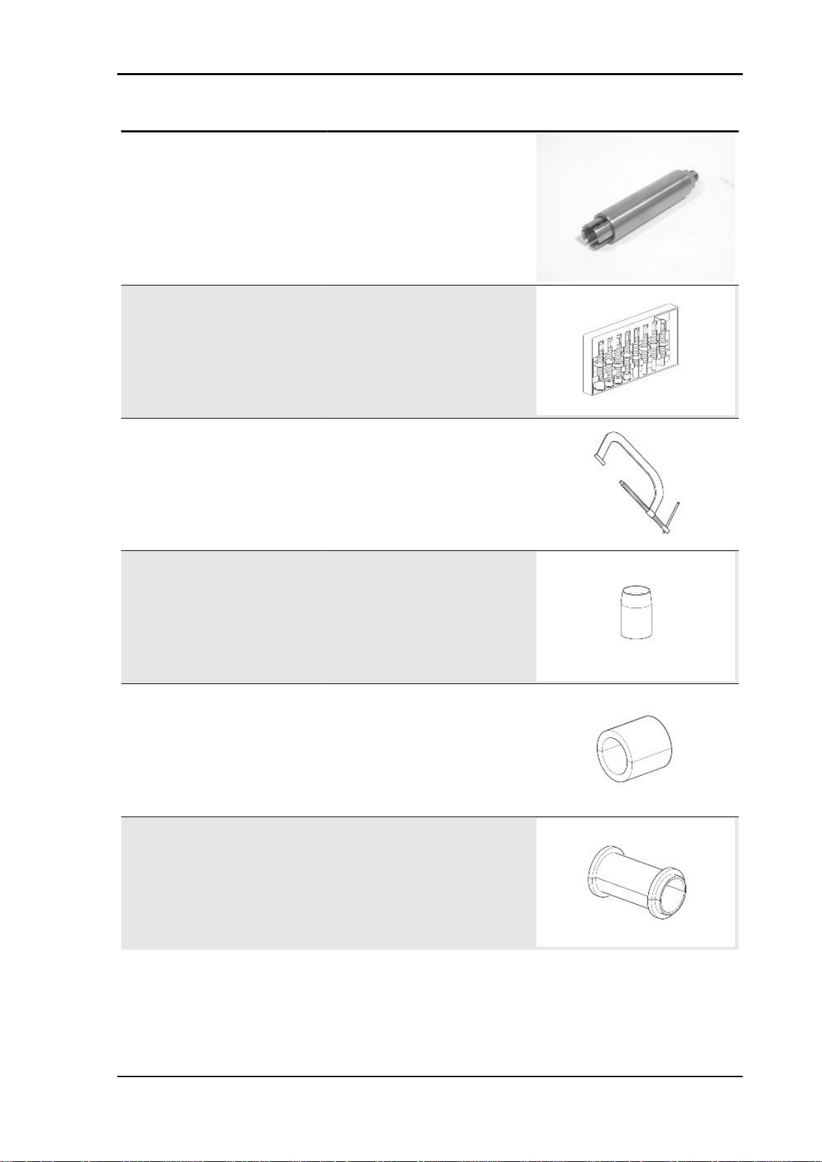
Unscrew and remove the rear coil fixing screw.
•
Slide off the rear coil.
•
Unscrew and slide off the rear spark
plug.
Engine oil
Check
NOTE
HOT OIL IS LESS VISCOUS AND WILL DRAIN OUT MORE EASILY AND COMPLETELY.
•
Shut off the engine and wait for a few
seconds.
•
Keep the vehicle upright with both
wheels on the ground.
•
Ensure that the vehicle is on a level
surface.
•
Check, via the sight glass positioned
on the clutch casing, that the oil level
reaches at least three quarters of the
way up the sight glass itself.
•
If this is not the case, top-up the oil immediately through the filler plug.
CAUTION
THE OIL LEVEL MUST NEVER DROP BELOW THE MINI-
MUM (MIDDLE OF THE SIGHT GLASS), NOR EXCEED THE
MAXIMUM (SIGHT GLASS COMPLETELY FULL) LEVELS;
FAILURE TO OBSERVE THE MINIMUM AND MAXIMUM OIL
LEVELS MAY CAUSE SERIOUS DAMAGE TO THE ENGINE
Replacement
NOTE
HOT OIL IS LESS VISCOUS AND WILL DRAIN OUT MORE EASILY AND COMPLETELY.
MAIN - 62
Page 63

RSV4 Factory Maintenance
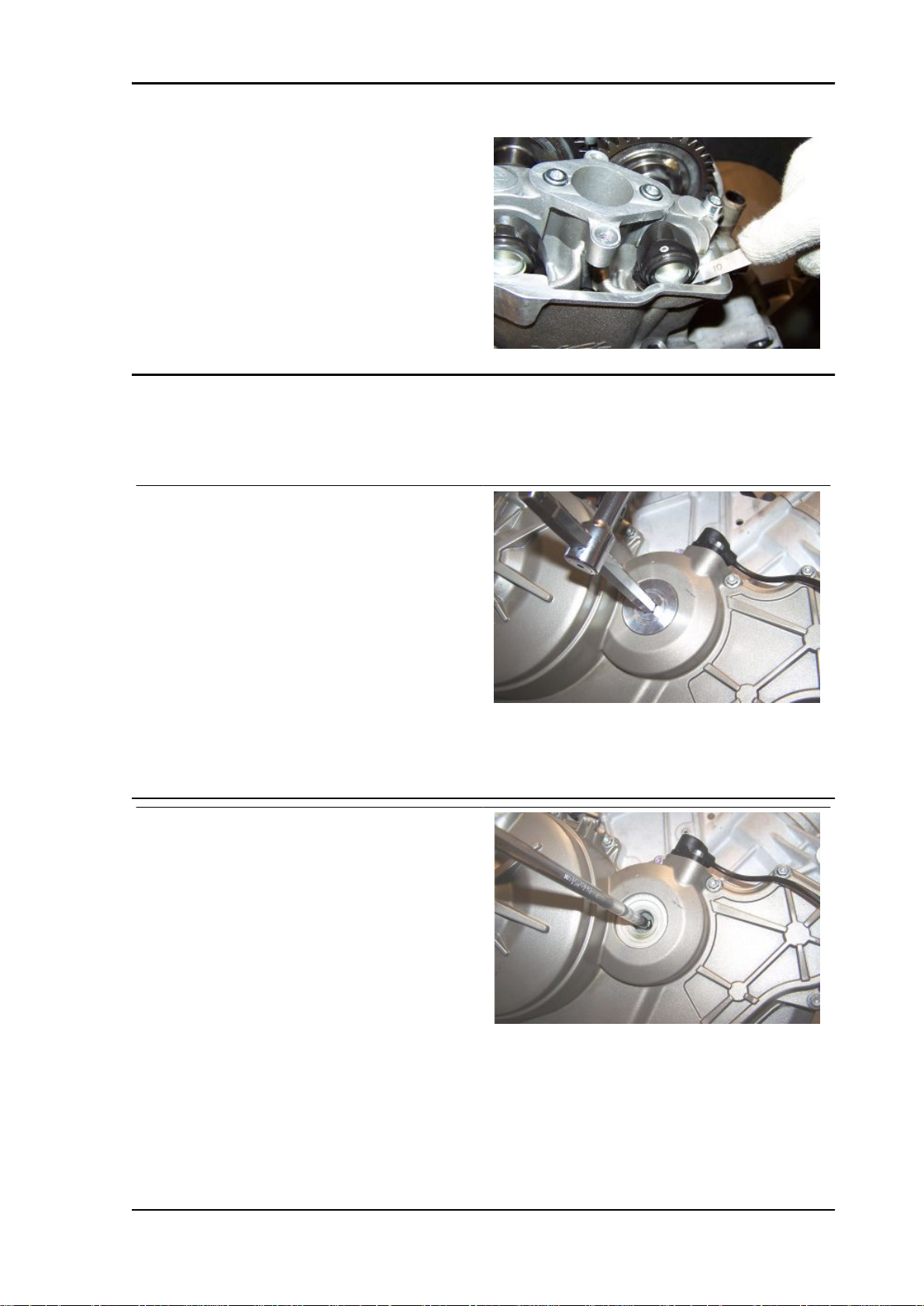
•
Place a container with a larger capacity
than the circuit under the drainage
plug.
•
Unscrew and remove the drainage
plug.
•
Unscrew and remove the filler cap.
•
Drain the oil into the container; allow
several minutes for oil to drain out completely.
•
Check and, if necessary, replace the
drainage plug sealing washers.
•
Screw and tighten the drainage plug.
•
Add 4 l (0.88 UK gal) of new engine oil
of the specified type.
•
Screw on the filler cap.
•
Warm up the engine up by running it for
a few minutes, then switch it off. After
thirty seconds, check the level in the
sight glass. Top up if necessary.
CAUTION
THE OIL LEVEL MUST NEVER DROP BELOW THE MINI-
MUM (MIDDLE OF THE SIGHT GLASS), NOR EXCEED THE
MAXIMUM (SIGHT GLASS COMPLETELY FULL) LEVELS;
FAILURE TO OBSERVE THE MINIMUM AND MAXIMUM OIL
LEVELS MAY CAUSE SERIOUS DAMAGE TO THE ENGINE
Engine oil filter
Replace the engine oil filter each time you
change the engine oil.
•
Drain the engine oil completely.
•
Unscrew and remove the engine oil filter from its seat.
NOTE
NEVER REUSE AN OLD FILTER.
MAIN - 63
Page 64

Maintenance RSV4 Factory
•
Spread a thin layer of oil on the sealing ring of the new engine oil filter.
•
Insert and screw the new engine oil filter in the seat, filling the filter to 1/3 of its capacity with
engine oil before fitting.
See also
Replacement
Air filter
•
Remove the fuel tank.
•
Unscrew and remove the eight air filter
box cover screws
•
See also
Fuel tank
•
Disconnect the upper injector fuel delivery union.
Disconnect the variable geometry intake system connector.
MAIN - 64
Page 65

RSV4 Factory Maintenance
•
Fit a suitably sized shim behind the filter box cover.
•
Lift the filter box cover on which the
control unit is installed.
•
Do not rotate the cover excessively to
avoid straining the pipes and cables.
•
Plug the inlet duct opening with clean
paper
•
Unscrew and remove the three air filter
screws.
•
Remove the filter and replace it with a
new component of the same type.
•
Remove the air filter.
Checking the valve clearance
FRONT HEAD
•
Remove both throttle bodies and the
coils.
•
Remove the front head cover and the
spark plugs.
•
Remove the cap on the clutch cover in
See also
order to turn the crankshaft, taking care
not to lose the O-ring.
MAIN - 65
Page 66

Maintenance RSV4 Factory
Removing the throttle body
Spark plug
Head cover removal
•
Use a feeler gauge to check the clearance between the cam of the shaft and
the relative tappet for both front head
shafts.
Characteristic
Acceptable values with control clearance between cam and valve
intake: 0.10 - 0.15 mm (0.0039 - 0.0059 in) exhaust: 0.20 - 0.25 mm (0.0079 - 0.0098 in)
REAR HEAD
•
Remove both throttle bodies and the spark plugs.
•
Remove the rear head cover.
See also
Removing the throttle body
Spark plug
Head cover removal
•
Use a feeler gauge to check the clearance between the cam on the shaft and
the relative tappet for both rear head
shafts.
Characteristic
Acceptable values with control clearance between cam and valve
intake: 0.10 - 0.15 mm (0.0039 - 0.0059 in) exhaust: 0.20 - 0.25 mm (0.0079 - 0.0098 in)
MAIN - 66
Page 67
RSV4 Factory Maintenance
Front cylinder head valves
•
Check the front valve head clearance and restore the correct clearance values if necessary,
proceeding as described below.
•
Remove both head covers, the alternator side cover and remove the cap
on the clutch cover in order to rotate
the crankshaft.
•
Remove the O ring.
See also
Head cover removal
Removing the flywheel cover
•
Turn the crankshaft from the hole on
the clutch cover.
•
Move cylinder piston 1 (left rear piston)
to the overlap TDC;
•
Turn the crankshaft 150° in the direction of engine rotation (direction of travel).
MAIN - 67
Page 68

Maintenance RSV4 Factory
•
Insert the pin from the flywheel side, in
the hole in the crankshaft.
NOTE
THE SPECIAL TOOL IS ONLY USED FOR IDENTIFYING
THE CORRECT CRANKSHAFT POSITION.
DO NOT USE IT FOR TIGHTENING OPERATIONS.
Specific tooling
020852Y Crankshaft timing pin
•
Align the intake camshaft with the specific hole on the U bolt.
•
Insert the specified pin.
Specific tooling
020851Y Camshaft timing pin
•
Remove the two crankshaft and camshaft reference pins.
•
Turn the crankshaft until the gear
screw covered by the head when the
hole on the camshaft gear is aligned
with the hole on the U bolt, is visible.
•
Block crankshaft rotation using one of
the specific tools.
•
Unscrew and remove the camshaft
gear screw.
•
Remove the crankshaft locking tool.
Specific tooling
020850Y Primary gear lock
020848Y Flywheel retainer
MAIN - 68
Page 69

RSV4 Factory Maintenance
Repeat the following operations:
•
move cylinder piston 1 (left rear piston)
to TDC;
•
turn the crankshaft 150° in the direction
of engine rotation (direction of travel) in
order to align the hole on the intake
camshaft with the specific hole on the
U bolt; this ensures that all the front
cylinder bank valve springs are decompressed.
•
Refit the camshaft timing pin in the hole
of the front head U bolt and the crankshaft timing pin from the flywheel side.
•
Remove the camshaft timing pin.
•
Unscrew and remove the two U bolt
screws (1).
•
Remove the U bolt and the oil pipe.
Specific tooling
020851Y Camshaft timing pin
020852Y Crankshaft timing pin
•
Block crankshaft rotation using one of
the specific tools.
•
Unscrew and remove the second intake camshaft gear screw.
•
Leave the gear on the camshaft.
Specific tooling
020848Y Flywheel retainer
020850Y Primary gear lock
•
Install the specific camshaft gear support tool.
•
Fix it to the head using the two screws
(1).
•
Move the gear from the camshaft to the
tool.
Specific tooling
MAIN - 69
Page 70

Maintenance RSV4 Factory
020865Y Support for camshaft gear on head
•
Unscrew and remove the eight screws
(2), proceeding in stages and diagonally.
•
Retrieve the washers from the screws
near the spark plug holes.
•
Remove the U bolts with the O rings
and locator pins.
•
Remove the intake and exhaust camshafts.
If the two camshafts are timed correctly, the exhaust camshaft gear tooth (indicated with a dot) is
meshed with the trough of the intake camshaft
gear (indicated with two dots).
•
Use a magnet to remove the tappet.
CAUTION
REMOVE THE TAPPET CAREFULLY AS THE PAD MAY FALL INTO THE ENGINE.
•
Retrieve the pad and replace with a
suitable component to achieve the correct valve clearance.
Refer to the table: "Calibrated pad thicknesses" to identify the suitable thickness.
•
Fit the tappet.
See also
Calibrated pad thickness
MAIN - 70
Page 71

RSV4 Factory Maintenance
•
Install the intake and exhaust camshafts on the front head, bearing in
mind that:
the exhaust camshaft gear tooth (indicated with a
dot) is meshed with the trough of the intake camshaft gear (indicated with two dots).
CLEAN THOROUGHLY THE SEATS OF THE GEAR RETAINER SCREWS, ON THE INTAKE CAMSHAFT.
•
Fit the U bolts with the nine O rings and
locator pins.
•
Fit the new washers under the screws
(2) near the spark plug holes only.
•
Tighten the seven screws (2) operating
in stages and diagonally.
•
Do not fit the eighth screw (2 - fastening
the oil pipe) yet.
•
Move the gear from the mounting tool
to the camshaft.
•
Unscrew and remove the two screws
(1).
•
Remove the tool.
Specific tooling
020865Y Support for camshaft gear on head
•
Fit the U bolt and the oil pipe.
•
Tighten the two U bolt screws (1) and
the screw (2) that was not fitted previously.
MAIN - 71
Page 72

Maintenance RSV4 Factory
•
Align the intake camshaft with the specific hole on the U bolt.
•
Insert the specified pin.
Specific tooling
020851Y Camshaft timing pin
•
Apply Loctite 243 threadlock on the
timing gear screw.
•
Apply and loosely tighten the gear fixing screw on the camshaft.
•
Block crankshaft rotation using one of
the specific tools.
•
Tighten the gear fixing screw on the
camshaft to exactly the torque specified.
•
Remove the crankshaft locking tool.
Specific tooling
020848Y Flywheel retainer
020850Y Primary gear lock
•
Remove the two crankshaft and camshaft reference pins.
•
Turn the crankshaft until the gear
screw covered by the head when the
hole on the camshaft gear is aligned
with the hole on the U bolt, is visible.
•
Block crankshaft rotation using one of
•
MAIN - 72
the specific tools.
Apply Loctite 243 threadlock on the
second gear screw.
Page 73

RSV4 Factory Maintenance
•
Tighten the second gear camshaft control gear screw rigourously to the torque value.
•
Remove the crankshaft locking tool.
Specific tooling
020848Y Flywheel retainer
020850Y Primary gear lock
020851Y Camshaft timing pin
020852Y Crankshaft timing pin
•
Turn the crankshaft back to the previous position in which the camshaft and U bolt holes
were aligned; insert the reference pin while checking with the crankshaft reference pin, that
the flywheel side hole and the hole on the crankshaft are perfectly aligned.
•
If this is not the case, repeat the timing operations.
Specific tooling
020851Y Camshaft timing pin
020852Y Crankshaft timing pin
•
Check if the clearance between the cam on the shaft and the tappet is correct.
•
If not, repeat the valve clearance adjustment procedure.
Rear cylinder head valves
•
Check the rear valve head clearance and restore the correct clearance values if necessary,
proceeding as described below.
•
Remove the rear head cover and the clutch cover.
•
Move cylinder piston 1 (left rear piston) to the TDC;
•
Turn the crankshaft 450° (one complete turn + 90°) in the direction of motor rotation (direction
of travel).
•
Insert the pin from the clutch side into
the hole in the crankshaft.
NOTE
THE SPECIAL TOOL IS ONLY USED FOR IDENTIFYING
THE CORRECT CRANKSHAFT POSITION.
DO NOT USE IT FOR TIGHTENING OPERATIONS.
Specific tooling
020852Y Crankshaft timing pin
See also
Head cover removal
Removing the
MAIN - 73
Page 74

Maintenance RSV4 Factory
clutch cover
•
Align the intake camshaft with the specific hole on the U bolt.
•
Insert the specified pin.
Specific tooling
020851Y Camshaft timing pin
•
Remove the two crankshaft and camshaft reference pins.
•
Turn the crankshaft until the gear
screw covered by the head when the
hole on the camshaft gear is aligned
with the hole on the U bolt, is visible.
•
Block crankshaft rotation using one of
the specific tools.
•
Unscrew and remove the camshaft
gear screw.
•
Remove the crankshaft locking tool.
Specific tooling
020850Y Primary gear lock
020848Y Flywheel retainer
Repeat the following operations:
•
move cylinder piston 1 (left rear piston)
to TDC;
•
turn the crankshaft by 450° (one complete turn + 90°) in the direction of en-
MAIN - 74
gine rotation (direction of travel) to
align the hole on the intake camshaft
with the specific hole on the U bolt. This
ensures that all the rear cylinder bank
valve springs are decompressed.
Page 75

RSV4 Factory Maintenance
•
Refit the camshaft timing pin in the hole
in the rear head U-bolt and the crankshaft timing pin from the clutch side.
•
Remove the camshaft timing pin.
•
Unscrew and remove the two U bolt
screws (1).
•
Remove the U bolt and the oil pipe.
Specific tooling
020851Y Camshaft timing pin
020852Y Crankshaft timing pin
•
Block crankshaft rotation using one of
the specific tools.
•
Unscrew and remove the second intake camshaft gear screw.
•
Leave the gear on the camshaft.
Specific tooling
020848Y Flywheel retainer
020850Y Primary gear lock
•
Install the specific camshaft gear support tool.
•
Fix it to the head using the two screws
(1).
•
Move the gear from the camshaft to the
tool.
Specific tooling
020865Y Support for camshaft gear on head
•
Unscrew and remove the eight screws
(2), proceeding in stages and diagonally.
•
Retrieve the washers from the screws
near the spark plug holes.
•
Remove the U bolts with the O rings
and locator pins.
MAIN - 75
Page 76

Maintenance RSV4 Factory
•
Remove the intake and exhaust camshafts.
If the two camshafts are timed correctly, the intake
camshaft gear tooth (indicated with one dot) is
meshed with the trough of the exhaust camshaft
gear (indicated with two dots).
•
Use a magnet to remove the tappet.
CAUTION
REMOVE THE TAPPET CAREFULLY AS THE PAD MAY FALL INTO THE ENGINE.
•
Retrieve the pad and replace with a
suitable component to achieve the correct valve clearance.
Refer to the table: "Calibrated pad thicknesses" to identify the suitable thickness.
•
Fit the tappet.
See also
Calibrated pad thickness
•
Install the intake and exhaust camshafts on the rear head, remembering
that:
the intake camshaft gear tooth (indicated with a
dot) is inserted in the groove of the exhaust camshaft gear (indicated with two dots).
CLEAN THOROUGHLY THE SEATS OF THE GEAR RETAINER SCREWS, ON THE INTAKE CAMSHAFT.
MAIN - 76
Page 77

RSV4 Factory Maintenance
•
Fit the U bolts with the nine O rings and
locator pins.
•
Fit the new washers under the screws
(2) near the spark plug holes only.
•
Tighten the seven screws (2) operating
in stages and diagonally.
•
Do not fit the eighth screw (2 - fastening
the oil pipe) yet.
•
Move the gear from the mounting tool
to the camshaft.
•
Unscrew and remove the two screws
(1).
•
Remove the tool.
Specific tooling
020865Y Support for camshaft gear on head
•
Fit the U bolt and the oil pipe.
•
Tighten the two U bolt screws (1) and
the screw (2) that was not fitted previously.
•
Align the intake camshaft with the specific hole on the U bolt.
•
Insert the specified pin.
Specific tooling
020851Y Camshaft timing pin
MAIN - 77
Page 78

Maintenance RSV4 Factory
•
Apply Loctite 243 threadlock on the
timing gear screw.
•
Apply and loosely tighten the gear fixing screw on the camshaft.
•
Block crankshaft rotation using one of
the specific tools.
•
Tighten the gear fixing screw on the
camshaft to exactly the torque specified.
•
Remove the crankshaft locking tool.
Specific tooling
020848Y Flywheel retainer
020850Y Primary gear lock
•
Remove the two crankshaft and camshaft reference pins.
•
Turn the crankshaft until the gear
screw covered by the head when the
hole on the camshaft gear is aligned
with the hole on the U bolt, is visible.
•
Block crankshaft rotation using one of
the specific tools.
•
Apply Loctite 243 threadlock on the
second gear screw.
•
Tighten the second gear camshaft control gear screw rigourously to the torque value.
•
Remove the crankshaft locking tool.
Specific tooling
020848Y Flywheel retainer
020850Y Primary gear lock
020851Y Camshaft timing pin
020852Y Crankshaft timing pin
MAIN - 78
Page 79

RSV4 Factory Maintenance
•
Turn the crankshaft back to the previous position in which the camshaft and U bolt holes
were aligned; Refit the reference pin while checking, using the crankshaft reference pin, that
the clutch side hole and the hole in the crankshaft are perfectly aligned.
•
If this is not the case, repeat the timing operations.
Specific tooling
020851Y Camshaft timing pin
020852Y Crankshaft timing pin
•
Check if the clearance between the cam on the shaft and the tappet is correct.
•
If not, repeat the valve clearance adjustment procedure.
Calibrated pad thickness
Pad thicknesses for adjusting valve clearance correctly:
1.75 mm (0.0689 in)
1.80 mm (0.0709 in)
1.85 mm (0.0728 in)
1.90 mm (0.0748 in)
1.95 mm (0.0768 in)
2 mm (0.0787 in)
2.05 mm (0.0807 in)
2.1 mm (0.0827 in)
2.15 mm (0.0846 in)
2.2 mm (0.0866 in)
MAIN - 79
Page 80

Maintenance RSV4 Factory
2.25 mm (0.0886 in)
2.3 mm (0.0905 in)
2.35 mm (0.0925 in)
2.4 mm (0.0945 in)
2.45 mm (0.0964 in)
2.50 mm (0.0984 in)
2.55 mm (0.1004 in)
2.6 mm (0.1024 in)
2.65 mm (0.1043 in)
2.7 mm (0.1063 in)
2.75 mm (0.1083 in)
2.8 mm (0.1102 in)
2.85 mm (0.1122 in)
2.9 mm (0.1142 in)
2.95 mm (0.1161 in)
3 mm (0.1181 in)
3.05 mm (0.1201 in)
3.10 mm (0.1220 in)
3.15 mm (0.1240 in)
MAIN - 80
Page 81

INDEX OF TOPICS
TROUBLESHOOTING TROUBL
Page 82

Troubleshooting RSV4 Factory
TROUBLESHOOTING PROCEDURE IF THE EFI WARNING LIGHT ON THE INSTRUMENT PANEL
TURNS ON OR IF THERE IS ABNORMAL ENGINE PERFORMANCE
CAUTION
BEFORE CARRYING OUT ANY TROUBLESHOOTING, CAREFULLY READ THE GENERAL TROUBLESHOOTING CONCEPTS FOR ELECTRICAL DEVICES AT THE BEGINNING OF THE CHECK
AND CONTROL SECTION IN THE ELECTRICAL SYSTEM CHAPTER.
•
1 - THE "EFI" WARNING LIGHT IS ON AND THE WORD "SERVICE" IS SHOWN or THE
"EFI" WARNING LIGHT IS FLASHING AND THE WORDS "URGENT SERVICE" ARE
SHOWN or ONE OF THE TWO SITUATIONS TAKES PLACE AND IS SUDDENLY OUT or
THERE IS ABNORMAL ENGINE PERFORMANCE
•
2 - CONNECT TO THE DIAGNOSIS INSTRUMENT THROUGH CONTROL UNIT BY SELECTING "SELF-ACQUISITION, APRILIA, RSV4"
•
3 - ARE CURRENT- "ATT"- or STORED- "MEM"- ERRORS SHOWN IN THE "ERRORS
DISPLAY" SCREEN PAGE?
YES, go to 4; NO, go to 11.
•
4 - IF THE ERROR IN THE CENTRAL WINDOW IS SELECTED AND "?" IS DISPLAYED,
PRESS THE KEY "?" TO OBTAIN FURTHER INFORMATION ABOUT THE ERROR. THEN
GO TO THE "ELECTRICAL SYSTEM/CHECKS AND CONTROLS" CHAPTER AND READ
THE INFORMATION CONCERNING THE DEFECTIVE COMPONENT
•
5 - ACCORDING TO WHAT IS INDICATED ABOUT THE ERROR/S, PROCEED AS SUGGESTED AND SOLVE THE PROBLEM
•
6 - WAS THE PROBLEM SOLVED BY REPLACING THE MARELLI CONTROL UNIT?
YES, go to 7; NO, go to 8.
•
7 - READ THE ACTIVATION PROCEDURE FOR A NEW CONTROL UNIT ON THE "ELECTRICAL SYSTEM/CHECKS AND CONTROLS/ECU/MARELLI CONTROL UNIT" CHAPTER - END
•
8 - SELECT "ERROR CLEARING" FROM THE "DEVICES ACTIVATION (INJECTOR
ICON)" SCREEN PAGE
•
9 - WAS THE PROBLEM SOLVED BY REPLACING THE THROTTLE GRIP SENSOR
(DEMAND) OR THE THROTTLE BODY?
•
10 - READ THE RESET PROCEDURE ON THE "ELECTRICAL SYSTEM/CHECKS AND
CONTROLS/THROTTLE GRIP POSITION SENSOR OR THROTTLE BODY" CHAPTER END
•
11 - CHECK IF THERE ARE CURRENT OR STORED ERRORS DETECTED BY THE INSTRUMENT PANEL REFERRING TO THE "DIAGNOSIS" CHAPTER, "INSTRUMENT
TROUBL - 82
NO, END; YES, go to 10
Page 83

RSV4 Factory Troubleshooting
PANEL ERRORS" SECTION. IF THERE ARE ERRORS PRESENT, SOLVE THE FAULT
AND SELECT "CLEAR ERRORS"; IF THERE ARE NO ERRORS PRESENT, go to 12
•
12 - IN THE "ENGINE PARAMETER READING" SCREEN PAGE, DOES THE "AIR TEMPERATURE" PARAMETER INDICATE A VALUE EQUIVALENT TO ROOM TEMPERATURE?
YES, go to 13; NO, note A
•
13 - IN THE "ENGINE PARAMETER READING" SCREEN PAGE, DOES THE ENGINE
TEMPERATURE PARAMETER WITH COLD ENGINE INDICATE A VALUE SIMILAR TO
THAT OF THE AIR TEMPERATURE PARAMETER? AFTER STARTING THE ENGINE,
DOES THE PARAMETER INCREASE GRADUALLY INDICATING A CORRECT VALUE?
YES, go to 14; NO, note B
•
14 - IN THE "ENGINE PARAMETER READING" AND THE "LAMBDA SENSOR CORRECTION" SCREEN PAGES, WITH ENGINE AT IDLE AND ENGINE TEMPERATURE AT >
65°C, DOES THE VALUE VARY WITHIN THE 0.85 - 1.15 RANGE?
YES, go to 15; NO, note C
•
15 - IN THE "ENGINE PARAMETER READING" WITH ENGINE AT IDLE AND ENGINE
TEMPERATURE >65°c, "FRONT THROTTLE CORRECTION" OR "REAR THROTTLE
CORRECTION", WITH ENGINE AT IDLE, ARE THE PARAMETERS INCLUDED WITHIN
(-0.8° - +0.8°) INTERVAL? AND IN THE SAME SCREEN PAGE, ARE THE "FRONT
THROT., POT. 1 (DEGREES)" AND " "REAR THROT., POT. 1 (DEGREES)", WITH ENGINE AT IDLE, > OR = A 0.5°? CAUTION: THE DIFFERENCE OF THE THROTTLE
CORRECTION VALUES BETWEEN THE REAR AND FRONT CYLINDER MUST NOT BE
>1°
YES, go to 16; NO, note D
•
16 - CHECK: ENGINE SPEED SENSOR, FUEL PRESSURE, INJECTORS (MECHANICAL
OPERATION), COILS (SPARK), ENGINE MECHANICS - END
Note A: SEE THE "ELECTRICAL SYSTEM/CHECKS AND CONTROLS/AIR TEMPERATURE SENSOR" CHAPTER.
Note B: SEE THE "ELECTRICAL SYSTEM/CHECKS AND CONTROLS/ENGINE TEMPERATURE
SENSOR" CHAPTER.
Note C: SEE THE "ELECTRICAL SYSTEM/CHECKS AND CONTROLS/LAMBDA PROBE" CHAPTER.
Note D: SEE THE "ELECTRICAL SYSTEM/CHECKS AND CONTROLS/THROTTLE BODY" CHAPTER.
See also
Checks and inspections
TROUBL - 83
Page 84

Troubleshooting RSV4 Factory
The engine does not start
THE ENGINE DOES NOT START, THE INSTRUMENT PANEL TURNS ON.
CAUTION
AXONE SHOULD BE WORKING PROPERLY AND UPGRADED AT LEAST TO THE 7.0.0 VERSION
OR THE PGDS UPDATED AT LEAST TO THE 3.0.0 VERSION
CAUTION
BEFORE ANY TROUBLESHOOTING, MAKE SURE THAT:
1) BATTERY VOLTAGE IS ABOVE 12V;
2) THE MAIN 30A FUSE IS NOT DAMAGED AND IS ADEQUATELY FITTED;
3) AUXILIARY FUSES ARE NOT DAMAGED AND ARE ADEQUATELY FITTED.
NOTE
THE RELAY NUMBER SPECIFIED REFERS TO THE WIRING DIAGRAM. THE POSITION OF THE
RELAY ON THE VEHICLE IS INDICATED IN THE "ELECTRICAL SYSTEM/COMPONENT LAYOUT/
RELAY LAYOUT" CHAPTER.
•
1- WITH THE KEY TURNED TO "ON", THE INSTRUMENT PANEL LIGHTS UP BUT NO
FAULT INDICATION IS SHOWN WITH INDICATION "SERVICE" OR "URGENT SERVICE"
BUT THE WORD ECU IS READ BELOW and THE PLUG SOCKET DISCONNECTED?
YES, go to CONTROL UNIT SUPPLY CHECK; NO, go to 2
•
2. IS THE FUEL PUMP ACTIVATED?
YES, go to 3; NO, go to FUEL PUMP CHECK
•
3. THE DIAGNOSIS INSTRUMENT COMMUNICATES WITH THE CONTROL UNIT? THAT
IS, AFTER SELECTING FUEL INJECTION, AND FOLLOWING THE INSTRUCTION, WITH
KEY SET TO "ON", THE PARAMETERS, STATUSES, ETC ARE READ?
YES, go to 4; NO, go to DIAGNOSIS INSTRUMENT CONNECTION CHECK
•
4. WITH DIAGNOSIS INSTRUMENT ("DEVICES ACTIVATION" SCREEN PAGE, INJECTOR ICON) CARRY OUT ACTIVATION OF A LOWER INJECTOR (IT IS ADVISED TO
DISCONNECT THE BLACK FUEL PUMP CONNECTOR AT PIN 4, ON THE RIGHT): IS
THE INJECTOR ACTIVATED?
YES, go to 5, NO, go to INJECTION RELAY 33 CHECK
5. DOES THE MOTOR TURN WHEN THE STARTER SWITCH IS PRESSED?
YES, SEE CHAPTER "ELECTRICAL SYSTEM/CHECK AND CONTROLS/ENGINE SPEED SEN-
•
6. WHAT DOES THE "START-UP ENABLING SWITCH" STATUS IN THE DIAGNOSIS
INSTRUMENT, DEVICES STATUS SCREEN PAGE, ICON 0/1 MEAN?
•
7. WHAT DOES THE "FALL SENSOR" STATUS IN THE DIAGNOSIS INSTRUMENT, DEVICES STATUS SCREEN PAGE, ICON 0/1 MEAN?
TROUBL - 84
SOR and if engine speed sensor works correctly, go to 16; NO, go to 6
YES, go to STARTER SWITCH CHECK; NO, go to 7
If NORMAL is shown, go to 8; if TIP OVER is shown, go to 12
Page 85

RSV4 Factory Troubleshooting
•
8. WITH THE SWITCH SET TO "RUN", WHAT DOES THE "RUN-STOP SWITCH" STATUS
ON THE DIAGNOSIS INSTRUMENT, DEVICES STATUS SCREEN PAGE, ICON 0/1
MEAN?
If "RUN" is shown, go to 9; if "STOP" is shown, go to 15
•
9. CHECK THROUGH THE DIAGNOSIS INSTRUMENT THE CORRECT OPERATION OF
THE SIDE STAND, THE NEUTRAL SENSOR, THE CLUTCH SENSOR: OPERATE ANY
DEVICE AND CHECK THE SUITABLE INDICATION ON THE DEVICE STATUS, ICON 0/1
SCREEN PAGE.
If there is a fault, go to 10; if everything works correctly, go to 11
•
10. ACCORDING TO THE FAULT, SEE CHAPTER "ELECTRICAL SYSTEM/CHECK AND
CONTROLS/NEUTRAL GEAR SENSOR" or "ELECTRICAL SYSTEM/CHECK AND CONTROLS/GEAR SENSOR" or "ELECTRICAL SYSTEM/CHECK AND CONTROLS/SIDE
STAND SENSOR" - END
•
11. REPLACE THE CONTROL UNIT - END
•
12. IS THE SENSOR, IN THE FRAME INTERNAL FRONT NICHE, IN VERTICAL POSITION?
•
13. REFER TO THE CHAPTER "ELECTRICAL SYSTEM/CHECKS AND CONTROLS/FALL
SENSOR"; INDICATION ON DIAGNOSIS INSTRUMENT ALWAYS "TIP OVER" - END
•
14. SET THE SENSOR TO THE CORRECT POSITION - END
•
15. REFER TO THE CHAPTER "ELECTRICAL SYSTEM/CHECKS AND CONTROLS/RUN
- STOP SWITCH"; INDICATION ON DIAGNOSIS INSTRUMENT ALWAYS "TIP OVER" END
•
16. CHECK OPERATION OF FUEL CIRCUIT PRESSURE AND ENGINE MECHANICAL
OPERATION - END
See also
Engine rpm sensor
Neutral sensor
Side
stand sensor
RUN/STOP switch
YES, go to 13; NO, go to 14
CHECK CONTROL UNIT POWER SUPPLY
•
1. WITH THE KEY TURNED TO "OFF" CHECK IF THERE IS BATTERY VOLTAGE AT PIN
52 OF THE CONTROL UNIT, CABLE HARNESS SIDE
YES, go to 2; NO, go to 5
•
2. WITH THE KEY TURNED TO "ON" THERE IS BATTERY VOLTAGE AT PIN 40 OF THE
CONTROL UNIT, CABLE HARNESS SIDE (IN CASE OF LACK OF POWER SUPPLY ON
TROUBL - 85
Page 86

Troubleshooting RSV4 Factory
PIN 42, "URGENT SERVICE" TURNS ON IN THE INSTRUMENT PANEL AND THE CONTROL UNIT INDICATES ERRORS RELATED TO THE FRONT AND REAR THROTTLE
BODY)
YES, go to 3; NO, go to 6
•
3. CHECK CONTINUITY WITH GROUND CONNECTION AT PIN 5 and 16
If there is continuity, go to 4; if there is not continuity, restore ground connection on the engine
front part or restore cable harness
•
4. REPLACE CONTROL UNIT, SEE "ELECTRICAL SYSTEM/CHECK AND CONTROLS/
CONTROL UNIT " THE PART RELATED TO NEW CONTROL UNIT ACTIVATION PROCEDURE - END
•
5. CHECK CONTINUITY red/blue CABLE up to secondary fuse D and red/white cable from
secondary fuse to 30 A main fuse CHECKING ALSO THE ENGINE - VEHICLE CABLE
HARNESS CONNECTOR - END
•
6. CHECK CONTINUITY OF RED/BROWN CABLE FROM PIN 40 TO PROTECTION RELAY 19 CHECKING ENGINE - VEHICLE ELECTRICAL SYSTEM CONNECTOR
If there is continuity, go to PROTECTION RELAY 19 CHECK; if there is not continuity, restore
cable harness - END
See also
Control unit
CHECK FUEL PUMP
•
1. WITH KEY SET TO "ON", DISCONNECT THE CONNECTOR AND CHECK THAT
THERE IS BATTERY VOLTAGE ON PIN 1
YES, go to 2; NO, go to 4
•
2. CHECK FUEL PUMP CONNECTOR AND CHECK THAT AT PIN 2 THERE IS GROUND
CONTINUITY
YES, go to 3; NO, go to 5
•
3. CHECK ON CONNECTOR ON THE PUMP SIDE, THE ELECTRICAL CHARACTERISTICS: between PIN 1 and PIN 2 there should be a resistance of 0.5 - 1 ohm - END
•
4. CHECK CONTINUITY OF ORANGE/GREEN CABLE FROM PUMP CONNECTOR TO
INJECTION RELAY 33 AND RESTORE CABLE HARNESS - END
•
5. RESTORE GROUND CONNECTION - END
DIAGNOSIS INSTRUMENT CONNECTION CHECK
TROUBL - 86
Page 87

RSV4 Factory Troubleshooting
•
1. CHECK CONTINUITY OF WHITE/BLUE CABLE FROM PIN 14 OF THE CONTROL UNIT
ON CABLE HARNESS SIDE TO PIN 3 OF THE BLACK CONNECTOR OF THE DIAGNOSIS
YES, go to 2; NO, go to 4
•
2. CHECK THE CONTROL UNIT CONNECTOR AS WELL AS THE DIAGNOSIS BLACK
CONNECTOR
YES, go to 3; NO, restore faulty connector - END
•
3. CHECK CORRECT OPERATION OF THE DIAGNOSIS INSTRUMENT CONNECTION
CABLE AND THE CORRECT INSTALLATION OF THE PLIERS ON THE BATTERY - END
•
4. CHECK ENGINE CABLE HARNESS - VEHICLE CABLE HARNESS CONNECTOR END
INJECTION RELAY 33 CHECK
•
1. CHECK CONTINUITY OF THE ORANGE/GREEN CABLE FROM THE LOWER INJECTOR AT PIN 3 OF THE INJECTION RELAY 33, ALSO CHECKING THE ENGINE CABLE
HARNESS - VEHICLE CABLE HARNESS CONNECTOR AND THE INJECTION RELAY
CONNECTOR
If there is continuity, go to 2; if there is not continuity, restore cable harness - END
•
2. WITH KEY SET TO "ON" IS THERE VOLTAGE ON RED/BROWN CABLE OF THE INJECTION RELAY CONNECTOR, ON THE CABLE HARNESS SIDE?
YES, go to 3; NO, go to 6
•
3. WITH KEY SET TO "ON" IS THERE VOLTAGE ON ORANGE CABLE OF THE INJECTION RELAY CONNECTOR, ON THE CABLE HARNESS SIDE?
YES, go to 4; NO, go to 7
•
4. CHECK CORRECT OPERATION OF THE RELAY, THAT IS, PROVIDING VOLTAGE
ON THE CORRESPONDING PIN TO THE RED/BROWN CABLE AND GROUND ON SPECIFIC PIN TO THE BROWN/BLACK CABLE IS THERE CONTINUITY BETWEEN THE
OTHER TWO RELAY PINS?
YES, go to 5; NO, replace the relay - END
•
5. REPLACE THE CONTROL UNIT - END
•
6. CHECK CONTINUITY OF RED/BROWN CABLE FROM THE INJECTION RELAY 33 TO
THE PROTECTION RELAY 19
If there is continuity, go to PROTECTION RELAY 19 CHECK; if there is not continuity, restore
cable harness - END
TROUBL - 87
Page 88

Troubleshooting RSV4 Factory
•
7. CHECK CONTINUITY OF THE CABLE FROM THE INJECTION RELAY 33 TO THE
PROTECTION RELAY 19: ORANGE (BETWEEN RELAY 33 AND FUSE F) and RED/
BROWN (BETWEEN FUSE RELAY F AND RELAY 19)
If there is continuity, go to PROTECTION RELAY 19 CHECK; if there is not continuity, restore
cable harness - END
PROTECTION RELAY 19 CHECK
•
1. WITH KEY SET TO OFF, DISCONNECT THE RELAY CONNECTOR AND CHECK
CONTINUITY OF BLUE CABLE WITH GROUND
If there is continuity, go to 2; if there is not continuity, restore cable harness - END
•
2. WITH KEY SET TO OFF, DISCONNECT THE RELAY CONNECTOR AND CHECK IF
THERE IS VOLTAGE ON RED/WHITE CABLE
YES, go to 3; NO, restore the cable harness - END
•
3. CHECK CORRECT OPERATION OF THE RELAY, THAT IS, PROVIDING VOLTAGE
ON CORRESPONDING PIN TO THE GREEN/BLUE CABLE AND GROUND ON SPECIFIC
PIN TO THE BLUE CABLE IS THERE CONTINUITY BETWEEN THE OTHER TWO RELAY
PINS?
YES, go to 4; NO, replace the relay - END
•
4. CHECK CONTINUITY OF THE GREEN/BLUE CABLE FROM THE KEY CONNECTOR
AT PIN 3 OF THE RELAY CHECKING ALSO THE KEY SWITCH CONNECTOR AND RELAY CONNECTOR
If there is continuity, go to 5; if there is not continuity, restore cable harness - END
•
5. WITH KEY SET TO OFF, CHECK IF THERE IS VOLTAGE ON RED/WHITE CABLE ON
THE KEY SWITCH CONNECTOR
YES, go to 6; NO, restore the cable harness - END
•
6. WITH KEY SET TO ON AND CONNECTOR DISCONNECTED, CHECK ON THE
SWITCH SIDE IF THERE IS LACK OF CONTINUITY BETWEEN THE TWO PINS CORRESPONDING TO THE RED/WHITE CABLE AND GREEN BLUE AND REPLACE THE
KEY SWITCH- END
•
1. WITH KEY SET TO "ON" DISCONNECT THE SWITCH CONNECTOR (4-ways black,
inside the bow) AND CHECK IF THERE IS VOLTAGE + 5V ON PIN 2 ON THE CABLE
HARNESS SIDE
TROUBL - 88
STARTER BUTTON CHECK
YES, go to 2; NO, go to 5
Page 89

RSV4 Factory Troubleshooting
•
2. WITH CONNECTOR DISCONNECTED (4-ways black, inside the bow) CHECK IF
THERE IS GROUND CONNECTION ON PIN 3, ON THE CABLE HARNESS SIDE
YES, go to 3; NO, go to 6
•
3. CHECK WITH CONNECTOR DISCONNECTED (4-ways black, inside the bow) ON THE
SWITCH SIDE, PUSHING THE SWITCH, IF THERE IS CONTINUITY BETWEEN PIN 2
AND PIN 3
YES, go to 4; NO, go to 7
•
4. REPLACE THE CONTROL UNIT - END
•
5. CHECK CONTINUITY OF PINK CABLE BETWEEN SWITCH CONNECTOR AND PIN
58 OF THE CONTROL UNIT, CHECKING ALSO THE ENGINE - VEHICLE CABLE HARNESS CONNECTOR
YES, go to 4; NO, restore the cable harness - END
•
6. CHECK CONTINUITY OF PINK/BLACK CABLE BETWEEN SWITCH CONNECTOR
AND PIN 4 OF THE CONTROL UNIT, CHECKING ALSO THE ENGINE - VEHICLE CABLE
HARNESS CONNECTOR
YES, go to 4; NO, restore the cable harness - END
•
7. REPLACE THE STARTER BUTTON COMPONENT - END
TROUBL - 89
Page 90
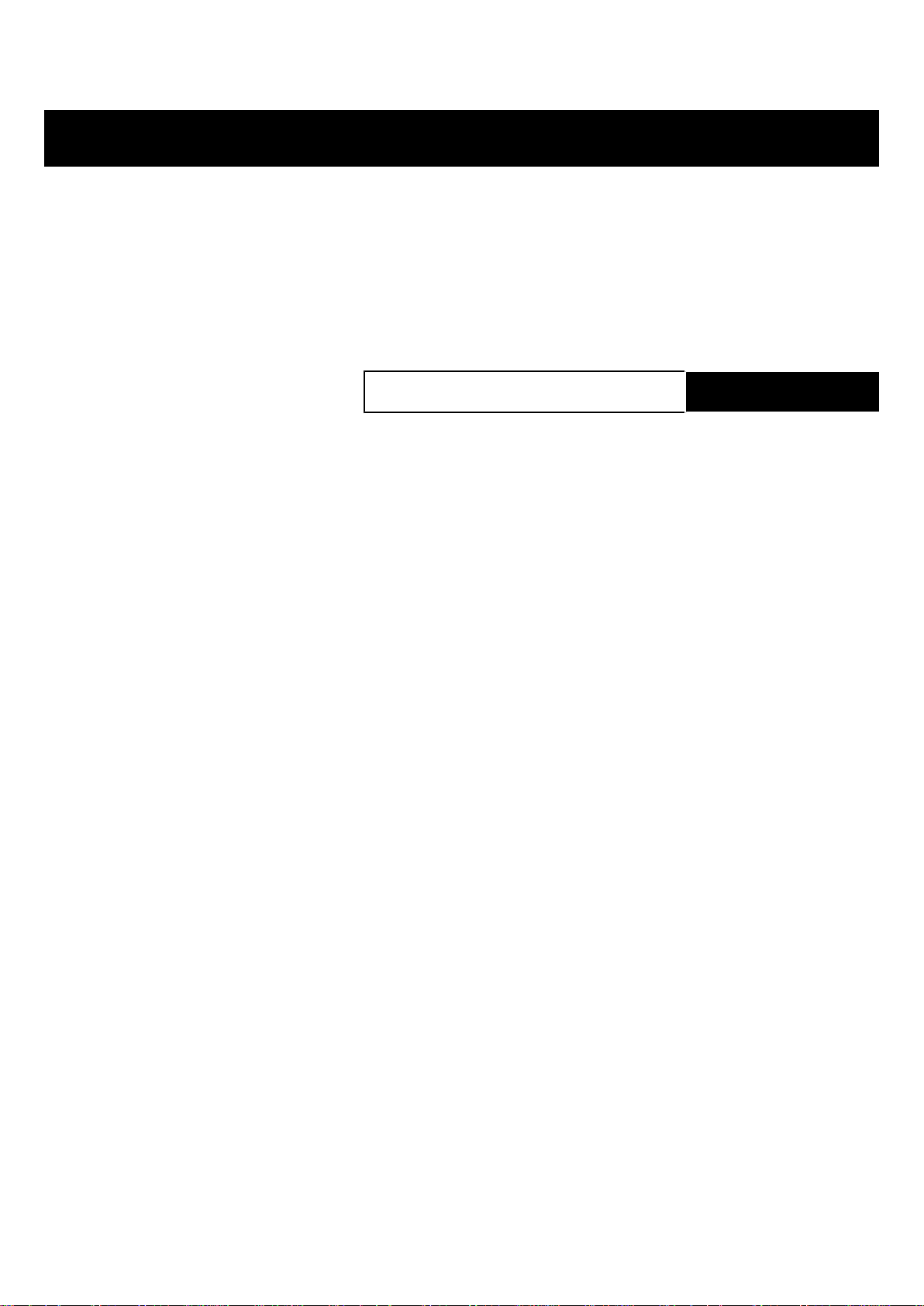
INDEX OF TOPICS
ELECTRICAL SYSTEM ELE SYS
Page 91

RSV4 Factory Electrical system
FRONT ELECTRICAL SYSTEM
pos.
1 Fall sensor mounting fixing screw M6 1 8 Nm (5.9 lbf ft) 2 Horn fixing screw M8 1 15 Nm (11.06 lbf ft) 3 Screw fastening the voltage regula-
4 Shear head screw (to the left of the
5 Right hand ignition lock screw M8 1 20 Nm (14.75 lbf ft) -
Description Type Quantity Torque Notes
M6 2 6 Nm (4.42 lbf ft) -
tor to the inner fairing
M8 1 Manual Tighten until the
ignition lock)
head shears off
ELE SYS - 91
Page 92

Electrical system RSV4 Factory
CENTRAL ELECTRICAL SYSTEM
pos. Description Type Quantity Torque Notes
1 Upper Silentblock nut, demand sen-
sor mounting bracket
2 Demand sensor fixing screw to
mounting plate
M6 1 5 Nm (3.69 lbf ft) -
SWP 4.9 4 1.2 Nm (0.88 lbf ft) -
Components arrangement
Key:
ELE SYS - 92
Page 93

RSV4 Factory Electrical system
1. Side stand sensor
2. Fuel pump
3. Instrument panel
4. Left hand switch
5. Right hand switch
6. Water Temperature Sensor
7. Cooling fans
8. Upper injectors
9. Air temperature sensor
10.Intake connectors
11.Lower injectors
12.Air pressure sensor
13.Outlet valve
14.Lambda probe
15.Speed sensor
16.Front headlamp
17.Rear turn indicators
18.Fall sensor
19.Horn
20.Voltage regulator
21.Battery
22.Auxiliary fuses
23.Control unit
24.Hand grip position sensor
25.Intake ducts connector control unit
26.Alternator
27.Coils
28.Timing sensor
29.Starter motor
30.Oil pressure sensor
A RELAY CANNOT BE IDENTIFIED BASED ON THE FOLLOWING INDICATIONS ONLY: THIS HAS
TO BE DONE ALSO IDENTIFYING THE COLOUR OF THE RELAY CABLES.
RELAY LAYOUT
Component position
in the electric diagram
10 Low-beam light relay Windshield front part
9 High-beam light relay Windshield front part
31 Start-up relay Rear undertail section
19 Protection relay Under the saddle next to the battery, left side
Component name Location on the vehicle
ELE SYS - 93
Page 94

Electrical system RSV4 Factory
Component position
in the electric diagram
33 Injection relay Under the saddle next to the battery, right side
36 Fan control relay In the niche of the headstock, on the left
25 Recovery logic relay (urgent service) In the niche of the headstock, on the right
Component name Location on the vehicle
Electrical system installation
INTRODUCTION
Scope and applicability
The purpose of this document is to define the position of the engine cable harness, its rounting and how
it is fixed on the engine and the filter box, any potential problems and particular checks to be carried
out on the connections and routings in order to reach the objectives of vehicle reliability.
Materials used and corresponding quantities
The electrical system consists of the following cable harnesses and parts:
•
1 Vehicle cable harness
•
1 Front light cable harness
•
1 License plate frame cable harness
•
1 Positive battery cable
•
1 Battery - engine ground cable
•
1 Key switch
•
1 Speed sensor
•
1 Start-up relay
•
5 Relays
•
1 Protection relay
•
1 Horn
•
1 Fall sensor
•
1 Headlamp
•
1 Taillight
•
1 Instrument panel
•
1 Right rear view mirror with turn indicator
•
1 Left rear view mirror with turn indicator
•
1 Rear right turn indicator
•
1 Rear left turn indicator
•
1 Fuel pump unit
•
1 Stand switch
•
1 Exhaust valve actuator
•
1 Oxygen sensor
•
2 Fans
•
1 Right handlebar control
ELE SYS - 94
Page 95

RSV4 Factory Electrical system
•
1 Left handlebar control
•
1 Regulator
•
1 Hand grip position sensor
•
1 Variable geometry control unit
•
1 Engine cable harness
•
1 Engine revolution sensor
•
1 Control unit 7SM
•
1 Air temperature sensor
•
1 Water temperature sensor
•
2 Coil with short cable (Cylinder 1 and Cylinder 4)
•
2 Coil with long cable (Cylinder 2 and Cylinder 3)
•
1 Gear sensor
•
1 Secondary air solenoid
•
1 Front motorised throttle body
•
1 Rear motorised throttle body
•
2 MAP sensor
•
1 Alternator
•
1 Starter motor
•
4 Upper injectors
•
4 Lower injectors (including the motorised throttle body)
Small parts and mountings
•
6 Large black clamps 178x4
•
6 Small black clamps 160x2.5
•
5 Rubber clamps
•
2 TBEI M6x30N screws
•
2 TE M6x20
•
1 flanged TE 6x16 screw
•
2 M5x8 screws
•
2 TBEI M5x16 screws
•
1 TE M6x30 screw
•
3 Self-tapping 5x14 screws
•
2 flanged TBEI M5x9 screws
•
1 M6 nut
•
2 Flanged self-locking M6 nuts
•
4 Cable grommets
•
1 Cable grommet
•
2 Cable grommets
ELE SYS - 95
Page 96

Electrical system RSV4 Factory
•
3 Cable guides
•
5 Relay socket rubber rings
•
2 Rubber rings
•
3 Rubber rings
•
2 Rubber rings
•
1 Rubber ring for the protection relay
•
1 Rubber ring for the fall sensor
•
1 AMP Superseal connector mounting
•
1 Relay/fall sensor mounting
•
1 Battery mounting bracket
•
2 T-shaped bushings
•
1 T-shaped bushing
•
2 T-shaped bushings
•
2 6.6x18x1.6 washers
•
1 Spring washer
•
1 5x20x1.5 washer
•
1 Spacer
•
1 Spacer
•
1 Exhaust valve opening cable
•
1 Exhaust valve closing cable
•
1 Instrument panel mounting cover
•
1 Heat-protecting cover
•
1 Control unit mounting
•
3 Large black 178x4 clamps
•
4 Self-tapping 5x20 screws
•
3 Self-tapping screws
•
3 Washers
•
3 Silentblocks
•
2 Self-tapping screws
•
4 AMP Superseal connector mountings
•
1 Mounting for the Framatome connector
•
2 Small black 98x2.5 clamps
•
1 Rubber clamp
•
1 Flanged M6x16 screw
•
1 Secondary air solenoid mounting
•
1 Secondary air pipe
•
1 Secondary air pipe
•
1 Secondary air pipe
ELE SYS - 96
Page 97

RSV4 Factory Electrical system
•
4 Rubber manifolds
•
4 Clic clamps
Motorcycle division
The wiring distribution is subdivided in three essential sections, as indicated in the figure.
1. Front section
2. Central section
3. Rear section
Special checks for the correct connection and laying of cables
It is extremely important that any security-locks for the following connectors are properly connected and
correctly tightened to ensure proper engine, and therefore proper vehicle, operation.
•
Instrument panel connector
•
Demand sensor connectors
•
Start-up relay connector
•
Speed sensor connector
•
Fall sensor connector
•
Safety relay connector
•
Protection relay connector
•
Injection relay connector
•
Taillight connector
•
Fuel pump connector
•
Exhaust valve actuator connector
•
Engine-vehicle interface connector
•
Flywheel connector
•
Regulator connector
•
Fan connectors
•
Starter motor eyelet
•
Stand switch connector
•
Right handlebar control connector
•
Left handlebar control connector
ELE SYS - 97
Page 98

Electrical system RSV4 Factory
•
Clutch connector
•
Key switch connector
•
Immobilizer aerial connector
•
Oxygen sensor connector
•
Output "30" engine revolution sensor connector
•
Outputs "25" and"26" 7SM control unit connectors
•
Outputs "29", "8", "7" and "28" coil connectors
•
Output "15" gear sensor connector
•
Output "11" secondary air solenoid connector
•
Output "13" front motorised throttle body connector
•
Output "14" rear motorised throttle body connector
•
Outputs "11" and "27" MAP sensor connectors
•
Outputs "20", "21", "22" and "23" upper injector connectors
•
Outputs "5", "6", "16" and "17" lower injector connectors
The connectors in the list are circled in the different pictures. The listed connectors are considered more critical than the others because their disconnection could cause the vehicle to
stop or malfunction.
Obviously, the correct connection of the other connectors is also important and essential for proper
vehicle operation.
It is also important and essential that the instructions regarding the routing and fixing of the cable harness in the various areas are followed meticulously in order to guarantee functionality and reliability.
Front side
TABLE A - RELAY AND FALL SENSOR
MOUNTING PRE-FITTING
Check that the fall sensor has been positioned
correctly, with the arrow above the indication UPPER facing upward.
1. fall sensor
2. Fall sensor rubber ring
3. Relay
4. Fall sensor connector
5. Mounting
TABLE B - REGULATOR PRE-FITTING
6. Regulator
7. Regulator connector
8. Flywheel connector
9. Self-locking nut (x2)
ELE SYS - 98
Page 99

RSV4 Factory Electrical system
10. T-shaped bushing (x2)
11. TBEI M6x30 screw (x2)
12. Washer (x2)
TABLE C1 - HEADLAMP PRE-FITTING
The headlamp cable harness (23) and the two relays with a relay socket rubber ring (17) must be fit on
the headlamp (13) as shown in the photos below.
13. Headlamp
14. Left position light connector
15. Cable harness routing in the cable grommet
16. Cable grommet
17. Relay with relay socket rubber ring
18. Cable harness routing in the cable grommet
19. Right position light connector
20. Right low beam light connector
21. Vehicle cable harness interface connectors
22. High beam light connector
23. Headlamp cable harness
24. Left low beam light connector
ELE SYS - 99
Page 100

Electrical system RSV4 Factory
TABLE C2 - HEADLAMP PRE-FITTING
16. Cable grommet 17. Relay with relay socket
rubber ring 25. Cable harness routing behind the
relay
TABLE D - HANDLEBAR CONTROLS
26. Left handlebar control
27. Clutch connector
28. Right handlebar control
TABLE E - INSTRUMENT HOLDER ARCH
BRACE AND FRONT PART
Use a clamp (31) to fasten the vehicle cable harness, in correspondence of the grey taping, on the
specific seat located on the instrument holder arch
brace.
Connect the Immobilizer antenna connector (30)
to the corresponding cable harness connector.
29. Antenna connector
30. Key switch
31. Clamp
ELE SYS - 100
 Loading...