

Page 1
aprilia
N°
CODICE RICAMBI
ABCDE
spare parts code number
IUKSAPSFBD
F E GR NL CH DK N IRL
JSGP
This manual contains all the main information and the
instructions required for normal use and maintenance of
your vehicle.
For controls and check-ups that cannot be carried out
easily with the standard equipment supplied, we advise
you to consult our Agents who can assure you of quick
and careful servicing.
To keep your Aprilia motor-cycle always in perfect
operating conditions, we advise you to insist on original spares and to have repairs carried out only by
Aprilia Agents and Dealers.
When ordering spare parts from the Agent, always quote
the spares code which is stamped on a sticker placed
under the saddle.
It is a good idea to make a note of the identification code
in the space provided in this manual, so that you will
always have a record of it e ven if the identification stic ker
comes off.
For your own safety, alwa ys wear a crash helmet.
Manual Code
All information is purely indicative and may be subject to
variation without notice.
8201839
Page 2

Ce manuel contient les données principales et les instructions nécessaires pour les opérations d’utilisation
et entretien de le véhicule.
Pour les contrôles et les révisions qui ne peuvent
être effectués avec les moyens normaux, il est opportun de s’adresser à nos Concessionnaires qui
garantissent un service soigné et rapide.
Afin de conserver votre moto Aprilia en de parfaites
conditions, nous vous conseillons de toujours exiger
les pièces de rechange originales et de s’adresser
exclusivement pour les réparations aux Concessionnaires et aux Revendeurs Aprilia.
En demandant les pièces de rechange à votre Concessionnaire, spécifier le code des pièces de rechange poinçonné sur une plaquette située sous la
selle. Il est bon de reporter le numéro d’identification
dans l’espace réservé dans ce manuel afin de s’en
rappeler en cas de perte de la plaquette d’identification.
Im vorliegenden Heft sind die wichtigsten Daten, sowienützliche Anleitungen für die normale Verwendung
und Wartung Ihres Fahrzeuges zusammengestellt.
Für Kontroll- oder Überholungsarbeiten, die mit den
normalenWerkzeugen der Ausstattung nicht durchgeführt werden können, wenden Sie sich bitte an unsere Vertragshändler, welcheIhnen eine sorgfältige
und rasche Assistenz bieten können.
Um den einwandfreien Zustand Ihres Motorrades
lange zuerhalten, empfehlen wir Ihnen, stets Original
Ersatzteile zuverlangen und sich für Reparaturarbeiten aus-schliealich andie Vertragswerkstätten der Aprilia
zu wenden. Bei der Anforderung von Ersatzteilen bei
Ihrem Vertragshändler geben Sie bitte die auf dem
Aufkleber an derUnterseite des Sattels aufgedruckte
Kennummer an. Wirempfehlen Ihnen, diese Identifizierungsnummer an der bierfürvorgesehenen Stelle
dieses Heftes einzutragen, damit Siediese auch im
Falle von Verlust des Aufklebers stets zurHand haben.
Pour votre sécurité utilisez toujours le casque.
Manuel Code
Données à titre indicatif sujettes à des modifications
sans aucun préavis.
8201839
Für Ihre persönliche Sicherheit tragen Sie stets
einen Helm.
Heft Cod. Nr.
8201839
Die in diesem Heft angeführten Daten sind rein indikativ undunterliegen Veränderungen ohne vorherige
Benachrichtigung.
Page 3

&217(176
page
,1+$/7
Seite
Technical features ........................................................2
Identification data .......................................................13
Arrangement of controls .............................................14
Instructions for use .....................................................20
Instructions for maintenance ......................................32
Electrical system .........................................................62
Periodic maintenance chart ........................................70
Trouble shooting chart ................................................76
Cleaning the motor-cycle ............................................82
Long inactivity of the vehicle .......................................84
6200$,5(
page
Caractéristiques techniques .........................................2
Données d’identification .............................................13
Disposition des commandes .......................................14
Normes pour l’utilisation .............................................20
Normes pour l’entretien ..............................................32
Installation électrique ..................................................62
Fiche d’entretien périodique .......................................72
Tableau de recherche des pannes .............................78
Nettoyage de la moto .................................................82
Longue inactivité du véhicule .....................................84
Technische Eigenschaften ...........................................3
Identifizierungsdaten .................................................. 13
Anordnung der Steuerelemente .................................15
Betriebsanleitungen ....................................................21
Wartungsanleitungen ................................................. 33
Elektrische Anlage ......................................................63
Plan für die regelmäßige Wartung ..............................74
Störungssuche ........................................................... 80
Reinigung des Motorrades .........................................83
Längerer Stillstand der Maschine ...............................85
1
Page 4

7(&+1,&$/)($785(6
&$5$&7(5,67,48(67(&+1,48(6
(1*,1(
Model .............................................. AM5 H
Type ..............2 stroke single-cylinder with lamellar inlet
Forced circulation liquid cooling.
Separate lubrication.
Cylinder ..........Light alloy with GILNISIL surface coating
Bore and stroke ........................................ 40.3 x 39 mm
Displacement .......................................................49,7 cc
Compression ratio ...................................................12:1
Starting ............................................................... Electric
Clutch ..........................................Multi-disc of light alloy
*($5%2;
Front coupling - 5 gears
Rations: 1st = 3.00
2nd = 2.06
3rd = 1.53
4th = 1.23
5th = 1.04
2
0 AUTOMIX
2
in an oil bath.
027(85
Modèle ............................................ AM5 H
Type .......................Monocylindrique 2T avec aspiration
lamellaire. Refroidissement par liquide
avec circulation forcée. Lubrification séparée.
Cylindre ....................... en alliage léger avec application
superficielle de GILNISIL.
Alésage et course .................................... 40.3 x 39 mm
Cylindrée ................................................................. 49,7
Rapport de compression ......................................... 12:1
Démarrage ..................................................... Electrique
Embrayage ............. A disques multiples en alliage léger
%2,7('(9,7(66(
Embrayages frontaux - 5 vitesses
Rapports: 1èr = 3.00
2ème = 2.06
3ème = 1.53
4ème = 1.23
5ème = 1.04
0 AUTOMIX
2
en bain d’huile.
Page 5

7(&+1,6&+((,*(16&+$)7(1
02725
Modell ............................................. AM5 H
Typ .................... Einzylinder-2-Takt mit Lamellar-Einlaß
Zwangsumlauf-Wasserkühlung.
Zylinder ..............Aus Leichtmetall mit GILSINIL-Auflage
Bohrung und Hub ............................................ 40,3 x 39
Hubraum .................................................................. 49,7
Verdichtungsverhältnis ............................................ 12:1
Anlasser ...........................................................Elektrisch
Kupplung ..............Leichtmetall-Mehrscheiben im Ölbad
6&+$/781*
5-Gang-Klauenkupplung
Gänge: 1. = 3.00
2. = 2.06
3. = 1.53
4. = 1.23
5. = 1.04
0 AUTOMIX
2
Frischölschmierung.
3
Page 6

75$160,66,21
Primary ...................................Gears with helical teeth -
Ratio: 3.55 (Z = 20/71)
Secondary ............... Chain 1/2" x 3/16" = Roller Ø 7.75
75$160,66,21
Primaire .....................engrenages à dents hélicoidales -
Rapport: 3,55 (Z = 20/71)
Secondaire ..... A chaîne 1/2" x 3/16" = Rouleau Ø 7,75)
&$5%85(7725
Dell’Orto .................................................... SHA 14-12 M
Dell’Orto ..........................................................SHA 14-9
Dell’Orto ..........................................................PHBG 19
,*1,7,21
Type ................................................................electronic
Spark advance ....................1,5 mm before T.D.C. (20°)
Spark plug .....................Bosh W3 cc - Champion N2C -
NGK B8 ES
4
&$5%85$7(85
Dell’Orto ....................................................SHA 14-12 M
Dell’Orto ..........................................................SHA 14-9
Dell’Orto .......................................................... PHBG 19
$//80$*(
Type ............................................................electronique
Avance de référence ........ 1,5 mm avant le P.M.S. (20°)
Bougie ........................... Bosh W3 cc - Champion N2C -
NGK B8 ES
Page 7

h%(56(7=81*
Primärantrieb ..........................................Schrägzahnrad
Sekundärantrieb ........................... Mit Kette 1/2" x 3/16"
9(5*$6(5
Dell’Orto .................................................... SHA 14-12 M
Dell’Orto .......................................................... SHA 14-9
Dell’Orto ...........................................................PHBG 19
=h1'81*
Typ ............................................................. Elektronisch
Verstellung .......................1,5 mm VOR DEM v.o.t. (20°)
Zündkerze .....................Bosh W3 cc - Champion N2C -
Übersetzungsverhältnis: 3.55 (Z = 20/71)
= Rolle Ø 7.75
NGK B8 ES
5
Page 8

)8(/
Running-in (500 km) .................... premium grade petrol
RON min. 97
Afterwards .................................... premium grade petrol
RON min. 97
Fuel tank
capacity ....................12.2 lt. of which 2.5 lt. fuel reserve
with mechanical operation.
Oil tank capacity
for separate lubrication ..................1.3 lt. of which 0.35 lt
oil reserve
(see Lubricants Chart)
$/,0(17$7,21
Rodage (500 km) .................................... essence super
RON min. 97
Par la suite .............................................. essence super
RON min. 97
Capacité réservoir
du carburant .......................12,2 l. dont 2,5 l. de réserve
avec actionnement mécanique.
Capacité réservoir huile
lubrification séparée .............................1,3 l. dont 0,35 l.
de réserve
(voir Tableau des Lubrifiants)
/8%5,&$7,21
Gear box and primary transmission .............0.750 kg oil
(see Lubricants Chart)
Cooling .................. forced circulation of liquid by means
of a centrifugal pump
Cooling circuit capacity .......... 900 c.c. (mixture of water
and 60% liquid antifreeze)
(see Lubricants Chart)
Minimum working temperature .............................. -17°C
6
/8%5,),&$7,21
Boîte de vitesse et transmis. primaire ......0.750 kg huile
(voir Tableau des Lubrifiants)
Refroidissement ..............................................................
.........................................................................................
Liquide de refroidissement .....................capacité 900 cc
(mélange d’eau avec liquide antigel à 60%)
(voir Tableau des Lubrifiants)
Température Min. d’exercice ................................ -17°C
Page 9

=8)h+581*
Einfahren (500 km) ..........................Super ROZ min. 97
Im folgenden ....................................Super ROZ min. 97
Kraftstoff-
Tankkapazität ...................... 12,2 l, davon 2,5 l Reserve
Frischöl-Tankkapazität ........................ 1,3 l, davon 0,35
6&+0,(581*
Getriebe und Primärantrieb .........................kg. 0.750 Öl
Kühlung ................................Wasser-Zwangsumlauf mit
Kapazität des Kühlumlaufs .................... 900 cc (60%ige
Wasser-Frostschutz-Mischung)
Min. Betriebstemperatur .......................................-17° C
mit mech. Betrieb.
Reserve
(s. Schmiermitteltabelle)
(s. Schmiermitteltabelle)
Zentri fugalpumpe
(s. Schmiermitteltabelle)
7
Page 10

)5$0(
Structure with high-resistance double bearing tube.
&+$66,6
Structure à double poutre portante à haute résistance.
6:,1*$50
Single arm mounted on antifriction bushes.
6863(16,216
Front ......................................... Aprilia telehydraulic fork
Rear .....................Aprilia Progressive System Hydraulic
Rear wheel travel .............................................. 110 mm
%5$.(6
Front
Rear
8
monoshock absorber, centre distance 265 mm
.......................∅
.......................∅
with central pin ∅ 30, travel 110 mm.
290 mm disc with hydraulic control
220 mm disc with hydraulic control
)285&+(
En acier à profil rectangulaire monté sur douilles antifriction.
6863(16,216
Avant ...................fourche téléhydraulique Aprilia à pivôt
central ∅ 30 excursion 110 mm.
Arrière ..................................Aprilia Progressive System
Monoammortisseur hydraulique int. 265 mm.
Course roue arrière ...........................................110 mm.
)5(,16
Avant ...........à disque ∅ 290 mm avec commande hydr.
Arrière .........à disque ∅ 220 mm avec commande hydr.
Page 11

5$+0(1
Hochwiderstandsfähige Doppel-Trägerstruktur.
6&+:,1*(
Einarmschwinge auf Antifriktionslagern.
$8)+b1*81*(1
Vorne ...............................Telehydraulikgabel Aprilia mit
Hinten .................................. Aprilia Progressive System
Hub Hinterrad................................................... 110 mm.
%5(06(1
Vorne ......................................... Hydraulisch gesteuerte
Hinten ........................................ Hydraulisch gesteuerte
Zentralzapfen ∅ 30, Federweg 110 mm
Hydraul. Monostoßdämpfer int. 265 mm
Scheibenbremse ∅ 290 mm
Scheibenbremse ∅ 220 mm
9
Page 12
7<5(6
Front ......................................90/90 x 16" - 80/100 x 16"
pressure 2.0 bar
Rear ..................................... 110/80 x 17" - 100/80 x 17
pressure 2.1 bar
31(86
Avant ..................................... 90/90 x 16" - 80/100 x 16"
pression 2,0 bar
Arrière ...................................110/80 x 17" - 100/80 x 17
pression 2,1 bar
Low pressure cause imprecise handling
-
and a tendency to weave, in extreme
cases even difficulty in maintaining the
trajectory chosen.
Check the depth of the tyre tread often, if it
-
is less than the safety limit (2 - 3 mm.) replace the tyre.
Tyre pressure should always be checked
-
when the tyres are at environment temperature, that is, when the bike has not
travelled more than 1 km in the previous 2
or 3 hours.
5,06
Front .......................................................... Ø 16" x 2,15"
Rear .......................................................... Ø 17" x 2.75"
10
Une pression trop basse des pneus en-
-
traîne une conduite imprécise et la tendance à osciller. En cas extrême, des
difficultés de maintien de la trajectoire.
Contrôler souvent la profondeur de des
-
pneus. Si elle est inférieure à la limite de
sécurité (2-3 mm), changer le pneu.
La pression des pneus des pneus doit touj-
-
ours être contrôler quand les pneus sont à
une température ambiante c’est-à-dire
quand la moto n’à pas parcouru plus de 1
Km pendant les 2 ou 3 dernières heures.
-$17(6
Avant ......................................................... Ø 16" x 2,15"
Arrière ....................................................... Ø 17" x 2.75"
Page 13

%(5(,)81*
Vorne .....................................90/90 x 16" - 80/100 x 16"
Hinten ...................................110/80 x 17" - 100/80 x 17
Ein zu niedriger Reifendruck kann eine
-
Reifendruck 2,0 bar
Reifendruck 2,1 bar
unpräzise Lenkung und Neigung zu
Schwingungen verursachen. In manchen
Fällen kummt es auch zu Schwierigkeiten beim Halten deR Fahrbahn.
Prüfen Sie oft die Profiltiefe; wenn diese
-
unter der Sicherheitsgrenze liegt (2-3 mm),
ersetzt Sie den Reifen.
Der Reifendruck sollte gemessen werden,
-
wenn diese Umgebungstemperatur haben,
d.h. wenn das Motorrad in den letzten 2 bis
3 Stunden nicht mehr als 1 Km gefahren
ist.
)(/*(1
Vorne .........................................................Ø 16" x 2,15"
Hinten ........................................................Ø 17" x 2.75"
11
Page 14
',0(16,216
Max. length ..................................................... 1875 mm
Wheel base ..................................................... 1280 mm
Handlebar width ................................................ 640 mm
Max. height ..................................................... 1090 mm
Seat height ........................................................ 780 mm
Footboard height ............................................... 355 mm
',0(16,216
Longueur max ................................................. 1875 mm
Empattement ................................................... 1280 mm
Largeur du guidon ............................................. 640 mm
Hauteur max. à partir du sol ............................ 1090 mm
Hauteur selle-spl ............................................... 780 mm
Hauteur repose-pieds-sol .................................. 355 mm
$%0(6681*(1
Max. Länge ..................................................... 1875 mm
Radstand ......................................................... 1280 mm
Lenkerbreite ...................................................... 640 mm
Max. Bodenabstand ........................................ 1090 mm
Sattelhöhe vom Boden ...................................... 780 mm
Trittbretthöhe vom Boden ................................. 355 mm
12
Page 15
,'(17,),&$7,21'$7$
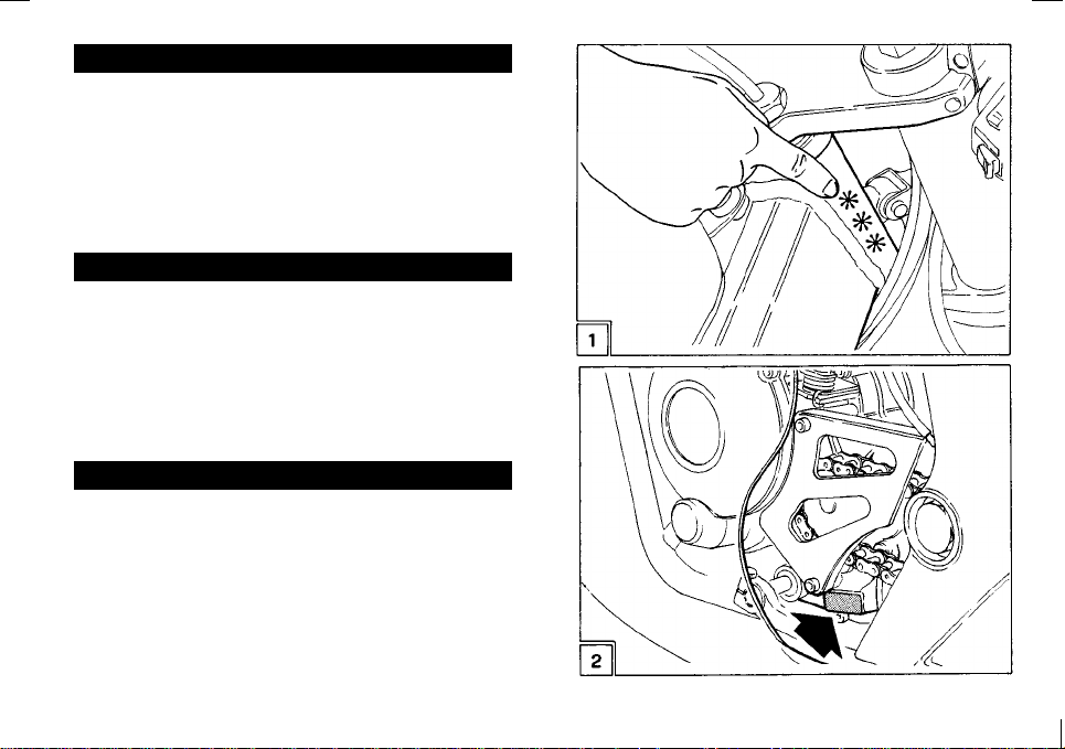
The frame approval numbers are stamped on the side of
the steering head (Fig. 1).
The motor identification numbers are stamped in the
space on the right-hand casing (Fig. 2).
'211((6'ª,'(17,),&$7,21
Les numéros d’homologation du châssis sont indiqués
(Fig. 1) sur la barre de direction et ceux du moteur dans
l’espace réservé situé sur le semi-carter gauche (Fig.
2).
,'(17,),=,(581*6'$7(1
Die Zulassungsnummern des Rahmens sind am Lenkungsrohr (Abb. 1), das Motor-Identifizierungszeichen
ist an der dafür vorgesehenen Stelle auf der rechten
Gehäusehälfte eingeprägt (Abb. 2).
13
Page 16

$55$1*(0(172)7+(&21752/6
',6326,7,21'(6&200$1'(6
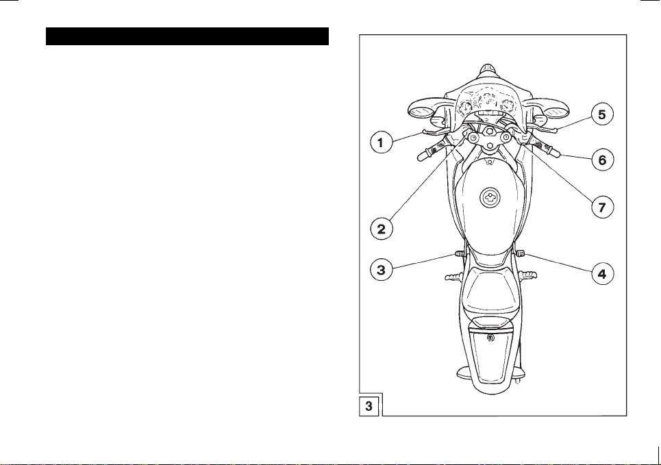
The controls of the RS 50 arranged as indicated in Fig.
3 are the following:
1) Clutch control lever
2) Lights and horn switch
3) Gear change control pedal
4) Rear brake control pedal
5) Front brake control lever
6) Accelerator handle
7) Electric start button
14
Les organes de commande de la RS 50 disposés selon
les indications de la Fig. 3 sont les suivants:
1) Levier de commande de l’embrayage
2) Déviateur des lumières avec avertisseur sonore
3) Pédale de commande de la boïte de vitesse
4) Pédale de commande du frein arrière
5) Levier de commande du frein avant
6) Poignée de commande gaz
7) Bouton démarrage électrique
Page 17
$125'181*'(567(8(5(/(0(17(
Die Steuerelemente der RS 50 sind wie auf Abb. 3 dargestellt angeordnet:
1) Kupplungshebel
2) Lichtschalter mit Hupe
3) Schaltpedal
4) Hinteres Bremspedal
5) Vorderer Bremshebel
6) Gasdrehgriff
7) Elektrischer Stopknopf
15
Page 18

7+(,*1,7,21.(<
+$6&/,&.326,7,216
1) Central position =
2) First click clockwise =
3) Second click clockwise =
(light switch)
4) Pressure and anticlockwise rotation =
(steering lock)
OFF
(stop)
(start)
ON
LIGHTS ON
LOCK
/$&/('ª$//80$*(
$'(&/,&6
1) Position centrale =
2) Premier déclic dans le sens horaire =
(allume)
2) deuxième déclic dans le sens horaire =
(feux allumes)
3) Pression et rotation dans le sens anti-horaire =
LOCK
(antivol)
OFF
(éteint)
ON
LIGHTS
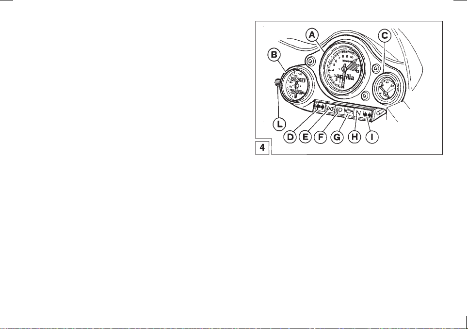
'$6+%2$5''(6&5,37,21
)LJ
A - Mechanical rev-counter
B - Speedometer with trip and twin total mileage
counter
C - Water thermometer
D - Green warning light (L.H. direction indicators)
E - Green warning light (dipped headlights)
F - Green warning light (main beam)
G - Red warning light (mixing tank level)
H - Green warning light (gears in neutral)
I - Green warning light (R.H. direction indicator)
L - Trip meter
16
'(6&5,37,217$%/($8'(%25'
)LJ
A - Compte-tours mécanique
B - Compte-kilomètres avec bi-totalisateur
C - Thermomètre eau
D - Voyants vert (feux de route)
E - Voyant vert (feux de croisement)
F - Voyants vert (feux de route)
G - Voyant rouge
(niveau huile dans le réservoir du mélangeur)
H - Voyant vert
(levier des vitesses au point mort)
I - Voyant vert (feux de route)
L - Compteur journalier
Page 19
'(5=h1'6&+/h66(/
+$767(//81*(1
1) Mittlere Stellung =
2) Erste Stellung im Uhrzeigersinn =
(eingeschaltet)
2) Zweite Stellung im Uhrzeigersinn =
(Lichter an)
3) Druck und Drehung gegen den Uhrzeigersinn =
,167580(17(1%5(77%(6&+5(,%81*
$EE
A - Mech. Drehzahlmesser
B - Kilometerzähler mit Doppelzählwerk
C - Wasserthermometer
DEFG - Rote-Kontrolleuchte (Ölstand im Mischtank)
H - Grüne-Kontrolleuchte (Neutral)
IL - Tageskilometerzähler
(Lenkschloß)
LOCK
Grüne-Kontrolleuchten (Fernlicht)
Grüne-Kontrolleuchte (Abblendlicht)
Kontrolleuchten (Fernlicht)
Grüne-
-Kontrolleuchten (Rechtungsanzeiger)
Grüne
(ausgeschaltet)
OFF
ON
LIGHTS
17
Page 20

/2&.6
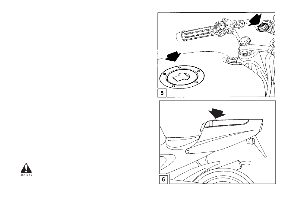
The motorcycle is supplied with a single key which operates:
Steering lock commutator (Fig. 5).
-
Petrol cap (Fig. 6).
-
Lock objects compartment (Fig. 6).
-
A hook is provided in the objects compartment for anchoring the helmet.
The helmet is hung on the hook.
When the lowered this prevents the helmet removal.
&5$6++(/0(7+22.
Thanks to this hook, you no longer have to carry the crash
helmet with yourself every time you park y our motorcycle.
To hang the crash helmet, raise the saddle, take out the
looped wire and pass it through the visor space or
through the fitted slot, then fix the loop to the hook.
Now lower the saddle and lock it.
To release the crash helmet from the hook, raise the
saddle, release the wire from the hook and lower the
saddle; before leaving, make sure that the wire doesen’t
get crushed and that the saddle is well locked.
Do not drive with your helmet fastened to
the hook, as this could compromise your
safety while driving.
6(5585(6
La cyclomoteur est munie d’une seule clé commandant:
Commutateur antivol (Fig. 5).
-
Bouchon essence (Fig. 6).
-
Serrure selle espace porte-objets (Fig. 6).
-
Pour le rangement du casque, un crochet situé dans l’epace porte-objets est prévu.
Le casque est accorché au crochet.
En refermant la selle, on empêche d’enleve le casque.
&52&+(73285/(&$648(
Grâce au crochet, il n’est pas nécessaire d’emporter
avec soi le casque chaque fois que l’on gare le cyclomoteur. Pour accrocher le casque, il faut soulever la selle,
ôter l’extrémité du câble à oeillet et l’enfiler à travers le
trou de la visière ou à travers le passant approprié, puis
fixer l’oeillet au crochet. A ce point, baisser la selle pour
bloquer.
Pour enlever le casque du porte-casque, soulever la
selle, libérer le câble du crochet et baisser la selle après
avoir contrôlé que le câble n’interfère pas et que la selle
soit bien fermée avant de démarrer.
Ne pas conduire avec le casque pendu au
porte-casque, car ceci pourrait comprommetre les conditions de sécurité pendant la
conduite.
18
Page 21
6&+/g66(5
Das Motorrad ist mit einem einzigen Schlüssel ausgestattet, der folgende Steuerungen durchführt:
Wählschalter für das Lenkschloß (Abb. 5)
-
Tankdeckelschloß (Abb. 5)
-
Schloss für Raum kleine Sachen (Abb. 6).
-
Für die Aufbewahrung des Helm ist ein Haken vorgesehen.
Der Helm wird an das Haken gehängt.
Wenn der geschlossen wird, kann das Helm nicht Abfuhr.
6&+87=+(/0+$/7(5
Dieser Haken ermöglicht es den Schutzhelm nicht Immer
mit sich nehmen zu müssen, wenn man das Motorrad abstellt. Um den Schutzbank heben, ein Ende des Seil mit
Öse herausziehen und durch das Visier oder den Kinnriemen ziehen, dann die Öse an den Haken befestigen.
Die Sitzbank wieder hinunterziehen und einrasten. Um
den Schutzheim vom Schutzhelmhalter wieder herauszunehmen, die Sitzbank heben, das Seil vom Haken abziehen und dann die Sitzbank wieder schließen. Vor dem
Losfahren, prüfen Sie ob das Seil nicht aus der Sitzbank
herausragt und ob die Sitzbank richtig eingerastet ist.
Fahren Sie nie mit dem Schutzhelm in der Halterung, us kan die Sicherheit beim Fahren gerährden.
19
Page 22

,16758&7,216)2586(
1250(63285/ª87,/,6$7,21
Before starting the vehicle for the first time, check that
-
the tyres are inflated to the correct pressure (front 2.0
Bar - rear 2,1 Bar) and fill the fuel tank with petrol
(RON min. 97).
Fill the separate lubrication tank with oil.
The motor must absolutely not be fed with
petrol blended at filling stations.
Check that there are no air bubbles in the oil feed
-
hose (between the oil tank and the pump); if necessary, bleed the pump by means of the screw provided.
20
Avant de mettre le véhicule en marche pour la pre-
-
mière fois, contrôler que les pneus soient gonflés à la
pression établie (2,0 Bar avant - 2,1 Bar arrière) et
remplir le réservoir du carburant avec de l’essence
(RON min. 97).
Remplir le réservoir avec de l’huile pour la lubrification séparée.
Le moteur ne doit absolument pas fonctionner alimenté par un mélange que l’on trouve
auprès des distributeurs.
V
érifier que le long du tuyau d’alimentation de
-
l’huile (du réservoir de l’huile à la pompe) il n’y
ait pas de bulles d’air; sinon, purger la pompe à
l’aide de la vis prévue.
Page 23

%(75,(%6$1/(,781*(1
Bevor Sie Ihre Maschine zum ersten Mal anlassen,
-
kontrollieren Sie, ob die Reifen den vorgeschriebenen
Druck aufweisen (Vorne 2,0 bar - Hinten 2,1 bar) und
füllen den Tank mit Super Benzin (ROZ min. 97).
Füllen Sie den Frischöltank mit Öl auf.
Der Motor darf auf keinen Fall mit an Tankstellen erhältlichen Gemischen betrieben
werden.
Vergewissern Sie sich, daß im Öl-Zuführungs-
-
schlauch (vom Öltank zur Pumpe) keine Luftbla-sen
auftreten; entlüften Sie die Pumpe gegeben- falls mittels der entsprechenden Schraube.
21
Page 24

5811,1*,1
The initial period of use is very important for the future
performance of the engine.
We advise warming up the engine before starting off,
allowing it to turn over for a few minutes at a low speed;
do not exploit the engine to the full and do not exceed
the maximum allowable rev number (
the sticker to this effect on the body).
After the first
500 Km
first service coupon
, have the bike checked with the
by an
APRILIA
4000 r.p.m.
Agent.
) (See
52'$*(
La première période d’utilisation est très importante
pour le rendement successif du moteur. On conseille de
chauffer le moteur avant de partir en le faisant fonctionner pendant quelques minutes à un bas nombre de
tours, de ne pas exploiter le moteur au maximum et de
ne pas dépasser le régime maximal consenti (
tours/min
nage). Au terme des
tuer le contrôle avec le
Concessionnaire
) (Voir adhésif correspondant sur le caré-
500 premiers kilomètres,
APRILIA
1er coupon
.
auprès d’un
4000
effec-
If there is no oil left in the separate lubrication tank, avoid using the vehicle with petroil
(in the fuel tank) as the motor would work
normally, but the lubrication pump would be
forced to turn over dry, which would cause
irreparable damage.
During the
and rear disc brakes, because the disc and the pads must
be run in before they can reach perfect working condition.
22
first 500 km
, brake several times with front
S’il n’y a plus d’huile dans le réservoir de la
lubrification séparée, éviter d’utiliser le véhicule avec un mélange (dans le réservoir
d’essence) car le moteur fonctionnerait normalement mais obligerait la pompe de lubrification à tourner à sec en l’endommageant
irréparablement.
Pendant les
sieurs freinages avec le frein avant et arrière à disque
car disque et plaquettes doivent être rodés avant de rejoindre la parfaite condition d’utilisation.
500 premiers kilomètres
, effectuer plu-
Page 25

(,1)$+5(1
Die Einfahrzeit ist sehr wichtig für die zukünftige Leistung Ihres Motorrades.
Es empfiehlt sich, den Motor vor der Fahrt für einige
Minuten bei niedriger Drehzahl warmlaufen zu lassen,
ihn nicht voll auszufahren und die Höchstdrehzahl
(
4000 U/Min.
kleber an der Verkleidung).
Nach den ersten
Kundendienst
durchführen.
) nicht zu überschreiten (Siehe auch Auf-
500 Km
bei einem
Sollten Sie sich ohne Öl im Frischöltank finden, vermeiden Sie es, Ihr Motorrad mit Gemisch (im Benzintank) zu betreiben, da der
Motor sonst zwar normal funktioniert,
jedoch die Schmierpumpe leer dreht und
einen nicht wieder gut zu machenden
Schaden davon tragen würde.
lassen Sie den
APRILIA
-Vertragshändler
ersten
Während der
sungen mit der vorderern und hinteren Bremse aus, da
Scheiben und Beläge erst nach einer gewissen Einlaufzeit ihre perfekten Betriebsbedingungen erreichen.
ersten 500 Km
führen Sie öfters Brem-
23
Page 26

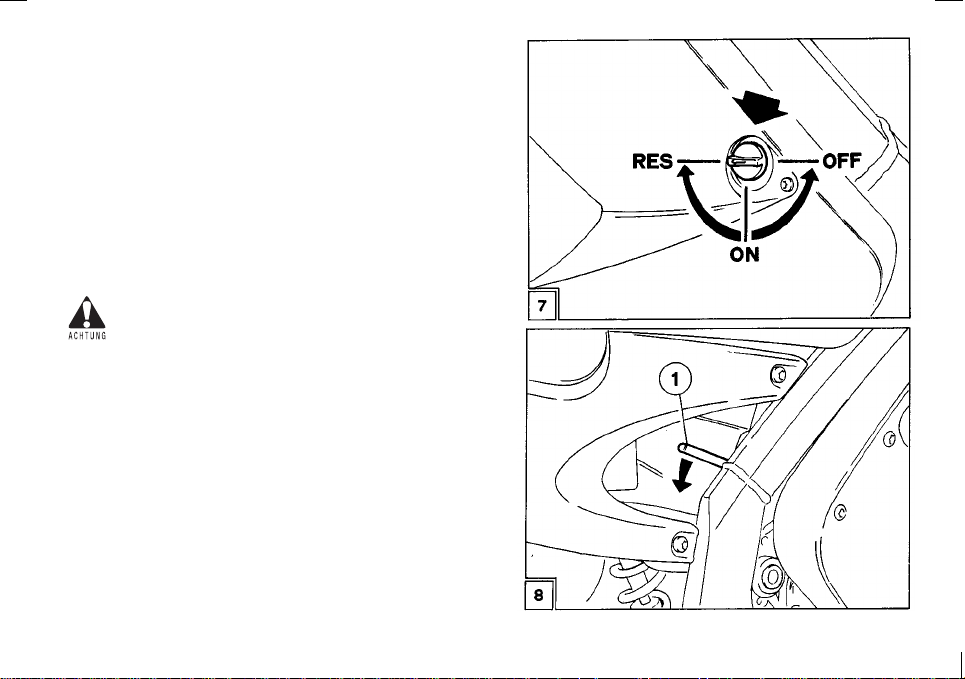
67$57,1*
Insert the ignition key and turn to ON position.
-
Turn on the fuel cock (Fig. 7) and set it at ON.
-
If the engine is cold, turn the starter, lowering the
-
lever of the carburettor (1-Fig. 8).
Set the gear in neutral or pull the clutch lever.
-
Then press the
-
Press the starter knob or press the starting lever hard
-
with your foot, turning the accelerator handle slightly.
START
button.
'(0$55$*(
Introduire la clé d’allumage et la tourner dans la posi-
-
-
-
-
-
.
tion
ON
Ouvrir le robinet du réservoir (Fig. 7) en le tournant
sur la position
Si le moteur est froid, insérer le starter en abaissant
le levier du carburateur (1-Fig. 8).
Mettre le levier des vitesses au point mort ou bien
tirer celui de l’embrayage.
Appuyer alors sur la touche
gèrement la poignée du gaz.
ON
.
en tournant lé-
START
Never run the engine in a closed area.
The exhaust contains poisonous carbon
monoxide gas that can cause loss of consciousness and may lead to death.
24
Ne jamais allumer le moteur en un lieu
fermé.
L’échappement contient du monoxyde de
carbone qui est dangereux et qui pourrait
provoquer une perte de conscience et même
la mort
Page 27
$1/$66(1
Zündschlüssel einstecken und auf Stellung
-
drehen.
Den Tankhahn (Abb. 7) durch Drehen auf Stellung
-
öffnen .
ON
Wenn der Motor kalt ist, schalten Sie den Starter ein,
-
idem Sie den Vergaserhebel nach unten drücken (1Abb. 8).
Schaltung auf Leerlauf stellen oder den Kupplung-
-
shebel gezogen halten.
Num den Startknopf drücken, indem Sie den Gasgriff
-
leicht drehen.
Lasses Sie den Motor nie in einem geschlossenen Raum an.
Das Auspuffgas enthält Kohlenmonoxid und
kann zu Ohnmacht führen oder sogar tödlich
sein.
ON
25
Page 28

Once you have started the engine, wait a few sec-
-
onds, turn the accelerator handle firmly as far as it will
go, thus automatically disconnecting the starter (
metallic click will be heard
When the engine is warm it should be started without
-
using the starter.
).
A démarrage advenu, attendre quelques secondes,
-
tourner énergiquement la poignée du gaz jusqu’à la
a
fin de course en actionnant ainsi le débranchement
automatique du starter (
métallique
A moteur chaud, le démarrage s’effectue sans star-
-
ter.
)
On entendra un déclic
26
The engine must not remain turned on with
-
the battery or the voltage regulator disconnected; this would cause irreparable damage to the electrical system.
Avoid pressing the start knob when the en-
-
gine is turned on, to avoid damaging the
starter motor.
Le moteur ne doit pas rester allumé avec la
-
batterie ou le régulateur de tension détachés car cela endommagerait irréparablement l’installation électrique.
Eviter d’appuyer sur la touche start à mo-
-
teur allumé pour ne pas endommager le démarreur.
Page 29

Nach dem Anspringen einige Sekunden warten und
-
den Gasgriff energisch drehen, um den Starter automatisch auszuschalten (
sches Einrastgeräusch
Bei warmem Motor wird ohne Starter angelassen.
-
Lassen Sie den Motor nie laufen, während
-
die Batterie oder der Spannungsregler abgehängt sind, da sonst die elektrische Anlage ernsthatt beschädigt würde.
Vermeiden Sie es, den Starterknopf zu
-
drücken, während der Motor bereits läuft,
um den Anlassermotor nicht zu beschädigen.
es erfolgt ein metalli-
).
27
Page 30

029,1*2))
After warming up the engine, pull the clutch, engage
(gear pedal downwards) (
gear
Then gradually release the clutch and turn the throttle at
the same time.
Fig. 9
).
1st
'(3$57
Après avoir fait chauffer le moteur, tirer l’embrayage,
mettre la
de vitesse vers le bas) (
lement l’embrayage et simultanément tourner la poignée du gaz.
1ère vitesse
(pédale du sélecteur de la boïte
). Puis, relâcher graduel-
Fig. 9
&+$1*,1**($5
Release the throttle, pull the clutch and lift the gear lever
upwards to change to the higher gears.
Vice versa, push downwards when changing to a lower
gear.
Before riding the motorcycle we advise
-
you to get to know the controls and all
their functions as explained in this manual.
Contact your APRILIA dealer if there is
-
anything you do not understand.
28
&+$1*(0(17'(69,7(66(6
Oter le gaz, tirer l’embrayage, soulever le levier des vitesses vers le haut pour passer aux vitesses supérieures. Viceversa, pousser vers le bas pour passer aux
vitesses inférieures.
Avant de conduire le cyclomoteur, il est
-
bon de se familiariser avec les commandes
et avec leurs fonctions reportées dans ce
manuel d’utilisation et entretien.
Consulter votre concessionnaire Aprilia
-
en cas d’incompréhensions.
Page 31

$1)$+5(1
Nachdem Sie den Motor angewärmt haben, betätigen
Sie die Kupplung und legen den
dal nach unten) (
langsam kommen und drehen gleichzeitig den Gasgriff.
*b1*(:(&+6(/1
Nehmen Sie das Gas weg, betätigen Sie die Kupplung
und heben Sie den Schalthebel nach oben an, um zu
einem größeren Gang zu wechseln. Um herunterzuschalten, treten Sie umgekehrt den Ganghebel nach
unten.
-
-
Abb. 9
Bevor Sie Ihre Motorrad fahren, empfeh
len wir Ihnen, sich mit den verschiedenen,
im vorliegenden Anleitungsheft beschrie
benen Steuerelementen undihrer Funktion
vertraut zu machen.
Für etwaige Klärungen steht Ihnen Ihr Aprilia-Vertragshändler gerne zur Verfügung.
1. Gang
). Nun lassen Sie die Kupplung
ein (Schaltpe-
29
Page 32

67233,1*7+((1*,1(
Release the throttle, set the gear in neutral and turn the
ignition key in an anticlockwise direction.
Turn off the fuel cock.
If there should be an excessive water temperature (over 105°C) during normal ope-ration, turn off the engine.
Wait for it to cool down, then check the level
of the liquid and top up if necessary.
$55º7'8027(85
Fermer la commande du gaz, mettre le levier des vitesses au point mort et tourner la clé d’allumage dans le
sens anti-horaire.
Fermer le robinet du réservoir de l’essence.
Si l’on constate une température de l’eau
trop élevée (plus de 105°C) pendant le fonctionnement normal de le cyclomoteur, arrêter le moteur, attendre son
refroidissement, puis contrôler le niveau du
liquide de refroidissement et éventuellement
en rajouter.
T
he coolant should be topped up when the engine
is cold, checking the level through the loading inlet
(Fig. 10).
If the level is normal, wait until the engine has cooled
before starting again and have the cooling system
checked by an
30
Aprilia
Dealer.
L’addition du liquide réfrigérant s’effectue à moteur froid
en vérifiant le niveau du radiateur à travers la goulotte
de remplissage (Fig. 10).
Si le niveau est normal, attendre que le moteur refroidisse avant de repartir et ensuite, faire contrôler l’installation de refroidissement par un Concessionnaire
Aprilia
.
Page 33

02725$%67(//(1
Schließen Sie die Gaszufuhr, stellen Sie die Schaltung
auf Leerlauf und drehen Sie den Zündschlüssel gegen
den Uhrzeigersinn. Schließen Sie den Tank-hahn.
Sollte sich während der normalen Funktion
Ihres Motorrad die Wassertemperatur
außergewöhnlich (über 105°C) erhöhen. Stellen Sie den Motor ab, warten Sie bis er abgekühlt ist, kontrollieren Sie dann den
Flüssigkeitsstand im Kühler, undfüllen evtl.
nach.
Das Nachfüllen der Kühlflüssigkeit erfolgt bei kaltem
Motor und der Stand wird über den Einfüllstutzen (Abb.
10) kontrolliert.
Sollte der Stand normal sein, warten Sie vor dem
Weiterfahren das Abkühlen des Motors ab und lassen
die Kühlanlage bei nächster Gelegenheit von einer
-Vertragswerkstatt kontrollieren.
Aprilia
31
Page 34

,16758&7,216)250$,17(1$1&(
1250(63285/ª(175(7,(1
The perfect efficiency and long life of the vehicle are
largely dependent on care in maintenance.
Before carrying out maintenance it is advisable to clean
the motor cycle.
*($52,/5(3/$&(0(17
)LJ
This operation should be carried out while the engine is
warm, the procedure is as follows:
remove the lower part of the fairing;
-
remove the silencer;
-
place a suitably sized receptacle under the engine to
-
collect the old oil;
unscrew the cap under the engine (Pos. 1);
-
once all the oil has drained off, replace the cap and
-
pour
0,750 cc
Lubricants Chart).
*($52,//(9(/
&+(&.,1*)LJ
Ensure that the motorcycle is standing in a vertical position with respect to ground level. Remove the checking
screw (right side case): (Pos. 1).
The oil is at the right level if it comes up to the lower edge
of the hole. Top up, if necessary, through the filler cap
(Pos. 2).
32
of oil into the filler cap (Pos. 2) (See
La parfaite efficacité et durée du véhicule dépendent
principalement d’un bon entretien.
Avant de procéder à un entretien, il est conseillé de nettoyer la moto.
&+$1*(0(17'(/ª+8,/('8027(85
)LJ
Le changement s’effectue à moteur chaud en procédant
de la façon suivante:
ôter la partie inférieure du carénage;
-
démonter le pot d’échappement;
-
placer un récipient de dimensions adéquates sous le
-
moteur pour recueillir l’huile usée;
dévisser le bouchon sous le moteur (Pos. 1);
-
quand l’huile sera complètement sortie, revisser le
-
bouchon et introduire
bleau des Lubrifiants) par le bouchon de remplissage
(Pos. 2).
9(5,),&$7,21'81,9($8'(/ª+8,/(
'(/$92,7('(9,7(66()LJ
Maintenir le cyclomoteur en position verticale par rapport au sol. Oter la vis de contrôle (carter latéral droit);
(Pos. 1) le niveau de l’huile est correct s’il rejoint la
marge inférieure du trou. D’éventuelles additions d’huile
s’effectuent par le trou d’introduction supérieiur (Pos. 2).
5(*/$*('(/ª(0%5$<$*(
0,750 cc
d’huile (voir
Ta-
Page 35

:$5781*6$1/(,781*(1
Die perfekte Leistungsfähigkeit und die Lebensdauer
der Maschine hängen zum großen Teil von der sorgfältigen Wartung ab.
Es empfiehlt sich, das Motorrad vor der Durchführung
von Wartungsarbeiten zu reinigen.
*(75,(%(g/:(&+6(/
$EE
Der Ölwechsel wird, um das Auslaufen des Öls zu erleichtern, bei warmem Motor wie folgt ausgeführt:
Den unteren Teil der Verkleidung abnehmen.
-
Den Auspuff abbauen.
-
Ein ausreichend großes Gefäß unter den Motor stel-
-
len, um das gebrauchte Öl aufzufangen.
Den Deckel unter dem Motor (Pos. 1) aufdrehen.
-
Sobald das Öl vollkommen ausgelaufen ist, den
-
Deckel wieder zuschrauben und über den Einfüllstutzen mit
0,750 cc
füllen (Pos. 2).
*(75,(%(g/67$1'.21752//(
$EE
Richten Sie das Motorrad gerade zum Untergrund aus.
Nehmen Sie die Kontrollschraube (an der linken Gehäusehälfte) ab (Pos. 1): Der Ölstand ist korrekt, wenn
er den unteren Rand der Öffnung erreicht. Eventuelles
Auffüllen wird über die obere Einfüllöffnung (Pos. 2)
vorgenommen.
Öl (siehe Schmiermitteltabelle) auf-
33
Page 36

&/87&+$'-8670(17
This model is equipped with two devices for adjusting the
length of the clutch cable.
From time to time check that the clutch cable is properly
adjusted and that the idle stroke of the control lever is
to 4 mm
If this distance is not correct, regulate the control lever
adjuster (Fig. 12) or the adjuster on the motor crank-case
(Fig. 13 - Pos. B).
. (Fig. 12).
If regulation is not possible by means of the
two adjusters, consult an Aprilia Dealer.
Ce modèle est muni de deux dispositifs de réglage pour
la longueur du câble de l’embrayage.
Contrôler périodiquement le réglage correct du câble de
l’embrayage en vérifiant que la course à vide du levier
3
de commande soit de
Si la mesure n’est pas respectée, agir sur le registre du
levier de commande (Fig. 12) ou bien, sur le re-gistre
situé sur le carter du moteur (Fig. 13 - Pos. B).
Si l’on ne peut pas régler par moyen de l’ecrou, il faut s’adresser à un Concessionaire
Aprilia.
3-4 mm
(Fig. 12).
Regulation should be carried out when the motorcycle
does not
the clutch pulled.
On the other hand if the clutch slips the acceleration of
the vehicle is not in proportion with the acceleration of
the engine.
34
release
properly and tends to move even with
Le réglage s’effectue quand le cyclomoteur n’embraye
pas correctement ou si elle tend à
l’embrayage tiré.
Au contraire, si l’embrayage glisse, on aura une accélération du véhicule non proportionnelle à l’accélération du moteur.
bouger
même avec
Page 37

.833/81*6(,167(//81*
Dieses Modell ist mit zwei Vorrichtungen zur Einstellung
der Länge des Kupplungskabels ausgesrtattet.
Die korrekte Einstellung des Kupplungskabels regelmäßig überprüfen; das Spiel des Steuerhebels soll
betragen (Abb. 12).
mm
Sollte das Spiel nicht diesem Wert entsprechen, mit
Hilfe der Stellschraube des Hebels (Abb. 12) oder mit
der entsprechenden Stellschraube auf dem Motorgehäuse (Abb. 13 - Pos. B) einstellen.
Sollte die Einstellung mittels der beiden
Stellschrauben nicht möglich sein, wenden
Sie sich bitte an Ihre Aprilia-Vertragswerkstatt.
3-4
Die Einstellung wird ausgeführt, wenn die Kupplung
nicht korrekt "
dazu, auch bei ausgekuppelter Kupplung anzufahren.
Wenn im Gegenteil die Kupplungs schleift, wird die Beschleunigung des Motorrads nicht der des Motores entsprechen.
auskuppelt
": das Motorrad neigt dann
35
Page 38

6(3$5$7(/8%5,&$7,21
The
an oil reservoir (
feed pump with variable capacity. (The capacity varies
according to the number of revs of the engine and the
throttle opening).
has a separate lubrication system, including
RS 50
1.3 it with reserve 0.35 lt
) and an oil
When the oil reaches reserve level a warning light
on the dashboard lights up.
The capacity is predetermined in the design phase, so
the user never has to make any adjustments.
It may be necessary to bleed air from the pump whenever
the pump is dismantled, the oil feed hose is detached, or
if the lubricant in the oil tank is completely used up.
In this case proceed as follows:
Empty the petrol tank and pour in
-
2 to 3 litres of
blended fuel containing 1% oil (see Lubricants
Chart).
Start the engine and let it idle.
-
Unscrew the bleeding screw (1-Fig. 14) and at the
-
same time completely open the pump control lever
(2-Fig. 14) so that the oil drains off, then tighten the
screw again.
Keep the pump control lever open until all the air
-
bubbles in the carburettor feed hose have completely
disappeared.
/8%5,),&$7,216(3$5((
L’
parée comprenant un réservoir de l’huile (
réserve de 0,35 l
huile à débit variable (son débit varie en fonction du
nombre de tours du moteur et de l’ouverture de la commande du gaz).
est munie d’une installation de lubrification sé-
RS 50
.) et une pompe d’alimentation de l’-
L’entrée en réserve est visualisée
1,3 l. avec
par l’allumage d’un voyant sur le tableau de
La débit est prédéterminée en phase de projet et
bord.
donc l’usager ne doit effectuer aucun réglage. La purge
de l’air de la pompe est nécessaire quand on démonte
la pompe, quand on détache le tuyau d’alimentation de
l’huile ou quand le lubrifiant du réservoir est terminé.
Dans ce cas, effectuer les opérations suivantes:
Vider le réservoir d’essence et le remplir avec
-
2-3
litres de mélange à 1% d’huile (voir Tableau
des Lubrifiants).
Allumer le moteur et le faire tourner au ralenti.
-
Dévisser la vis de purge (1-Fig. 14) et en même
-
temps ouvrir complètement le levier de commande de
pompe (2-Fig. 14) jusqu’à faire sortir l’huile puis serrer la vis.
Laisser ouvert le levier de commande de la pompe
-
jusqu’à ce que les bulles d’air aient complètement
disparues sur le tuyau d’alimentation du carburateur.
or greater safety we advise using up all
F
the blended fuel in the tank before refilling with premium grade petrol alone.
36
Pour une meilleure sécurité, il est conseillé
d’utiliser le mélange introduit dans le réservoir et seulement ensuite, remplir avec
juste de l’essence super.
Page 39

)5,6&+g/6&+0,(581*
Die
tattet, welche aus einem Öltank (
Reserve
tung je nach Drehzahl des Motores und der Gasöffnung
variert) für die Ölzuführung besteht.
ist mit einer Frischöl-Schmieranlage ausges-
RS 50
1,3 l mit 0,35 l
) und einer Verstellpumpe (deren Förderleis-
Die Reserve wird
durch das Aufleuchten einer Kontrollampe am
Armaturenbrett angezdeit.
werksseitig festgelegt und darf daher vom Kunden nicht
verstellt werden. Jedesmal, wenn die Pumpe ausgebaut, die Öl-Zuführleitung abgehängt wird oder wenn
das Schmiermittel im Tank vollkommen verbraucht
wirde, kann es vorkommen, daß die Entlüftung der
Pumpe erforderlicht ist.
In diese Falle wie folgt vorgehen:
Leeren Sie den Benzintank und füllen Sie ihn mit
-
Die Fördermenge ist
2-3
l 1%-igem Öl-Gemisch (siehe Schmiermitteltabelle) auf.
Lassen Sie den Motor an und bei Mindestdrehzahl
-
laufen.
Schrauben Sie die Entlüftungsschraube (1-Abb. 14)
-
auf und drehen Sie gleichzeitig den Steuerhebel der
Pumpe ganz (2-Abb. 14), bis das Öl ausläuft; nun
schrauben Sie die Schraube wieder fest.
Lassen Sie den Pumpenhebel offen, bis die Luft-
-
blasen im Zuführungsschlauch des Vergaser vollkommen verschwunden sind.
ür eine größere Sicherheit empfehlen wir,
F
das im Tank befindliche Gemisch zu verwenden und erst in der Folge ausschließlich mit Super Benzin nachzufüllen.
37
Page 40

Adjust the idling speed of the engine, then check
-
that the clearance of the oil pump and the carburettor is the same; if not, regulate the adjuster
provided in order to obtain a maximum clearance
1 mm
of
Check that there is no throttling in the feed hose and
-
the oil delivery hose; if they are throttled, change
them.
.
Régler le ralenti du moteur, puis contrôler que le jeu
-
du câble de la pompe huile et du carburateur soient
identiques.
Dans le cas contraire, agir sur les registres jusqu’à
obtenir un jeu max
Vérifier que le tuyau d’alimentation et celui de re-
-
foulement de l’huile ne présentent pas d’étranglements. Dans le cas contraire, les remplacer.
1 mm.
5($5%5$.($'-8670(17)LJ
Set the brake lever at the desired height (A) (in rest position) by means of the adjusting screw (on the lever).
Then, with the nut on the pump control rod (B), take up
the piston play so that it moves freely and is not locked.
&+(&.,1*%5$.(3$':($5
)LJ
Every 3000 km
as follows:
Remove the plastic cover (Pos. 1), levering it off with
-
a screwdriver.
Remove the seeger ring that holds the pad pin (Pos.
-
2).
Extract the pin (Pos. 3) by pulling it with pliers.
-
Extract the safety spring (Pos. 4) and the pads (Pos.
-
5).
The thickness of the friction material must be at least
. If it is any less, change the pads.
mm
)5217$1'5($5%5$.(6&+(&.,1*
38
. chec k the brake pad wear, proceeding
1.5
5(*/$*('8)5(,1$55,(5()LJ
A l’aide du registre de fin de course (A) (situé sur le levier), placer avant tout le levier du frein à la hauteur
désirée (en position de repos). Ensuite, à l’aide de l’écrou situé sur la tige de commande de la pompe (B), récupérer le jeu du piston de façon à ce qu’il puisse agir
librement et qu’il ne se bloque pas.
9(5,),&$7,21'(/ª8685(
'(63/$48(77(6)LJ
Tous les 3000 Km
procédant de la façon suivante:
Oter le couvercle en plastique (Pos. 1) en faisant de
-
levier avec un tournevis.
Oter la bague seeger qui fixe le goujon des pla-
-
quettes (Pos. 2).
Extraire le goujon (Pos. 3) en le tirant avec une pince.
-
Extraire le ressort de sécurité (Pos. 4) et les pla-
-
quettes (Pos. 5).
L’épaisseur du matériel de frottement doit être d’au
moins
1,5 mm
quettes.
, vérifier l’usure des plaquettes en
. Dans le cas contraire, changer les pla-
Page 41

Regulieren Sie die Leerlaufdrehzahl des Motores und
-
prüfen Sie, ob das Spiel des Kabels der Ölpumpe
und des Vergaserkabels gleich sind. Sollte dies nicht
der Fall sein, wirken Sie auf die entsprechenden
Stellschrauben ein, bis ein Max. Spiel von
reicht ist.
Prüfen Sie, ob die Zuführungsleitung und die
-
Ölauslass-Kabel keine Einschnürungen aufweisen;
falls ja, ersetzen Sie siel.
(,167(//81*'(5+,17(5(1%5(06(
$EE
Mit Hilfe der (am Hebel befindlichen) Einstellschraube
(A) des Endanschlages zunächst den Bremshebel auf
die gewünschte Höhe einstellen (in Ruhestellung); danach mit der Mutter an der Pumpensteuerungsstange
das Spiel des Kolbens wieder herstellen (B), so daß
dieser frei beweglich ist und nicht blockiert wird.
.21752//('(6%5(06%(/b*(
=867$1'6$EE
Nach jeweils 3.000 Km
Bremsbe- läge überprüfen. Dazu geht man folgendermaßen vor:
Den Plastikdeckel durch Anheben mit einem
-
Schraubenzieher abnehmen (Pos. 1).
Den Seegerring, der den Befestigungszapfen der
-
Bremsbeläge hält, abnehmen (Pos. 2).
Den Zapfen (Pos. 3) mit einer Zange herausziehen.
-
Die Sicherungsfeder (Pos. 4) und die Beläge heraus-
-
ziehen (Pos. 5).
Die Stärke des Reibungsmaterials muß mindestens
betragen. Andernfalls die Beläge ersetzen.
mm
muß man den Verschleiß der
1 mm
er-
1,5
39
Page 42

The RS 50 has a hydraulically controlled disc brake at
the front and rear.
The oil level in the pump reservoir (Fig. 17) must be
checked from time to time.
After the
-
crease in the idle stroke of the lever is noticed, the
hydraulic system must be bled to get rid of any air
bubbles that may have formed.
first 500 Km
or whenever an excessive in-
&21752/('8)5(,1$9$17(7$55,(5(
L’RS 50 possède le frein avant et arrière à disque avec
commande hydraulique. Périodiquement, il faut contrôler le niveau de l’huile dans le réservoir de la pompe
(Fig. 17) .
Après les
-
une augmentation excessive de la course à vide du
levier, l’installation hydraulique devra être purgée
d’éventuelles bulles d’air que se seraient formées.
500 premiers kilomètres
ou si l’on note
Brake fluid is corrosive and can cause damage.
40
Le fluide pour dreine est corrosif et peut
provoquer des dommages.
Page 43

.21752//('(5925'(5(181'
+,17(5(1%5(06(
Die
teuerte Scheibenbremsen.
Der Ölstand im Pumpentank muß regelmäßig kontrolliert werden (Abb. 17).
Nach den
-
Hebel ein übermäßiges Spiel aufweist, muß die Hydraulikanlage von den eventuellen Luftblasen befreit
werden.
hat vordere und hintere hydraulisch ges-
RS 50
ersten 500 Km
Die Bremsflüssigkeit ist korrosiv und kann
schäden verursachen.
und jedesmal, wenn der
41
Page 44

72%/(('7+()5217)LJ$1'5($5
)LJ%5$.(6
385*('(/ª+8,/('$16/()5(,16
$9$17)LJ(7$55,(5()LJ
Remove the protection cap of the caliper breather
-
valve (1).
Fit one end of a transparent PVC tube (2) over the
-
end of the caliper breather valve. The other end of
the tube must be placed in a receptacle to catch the
oil (3).
Remove the lid of the brake oil pump and check that
-
the level is correct. If necessary, top up.
Pull the control lever slowly and completely (2-3
-
times).
Keeping the lever in pulled position, open the
-
breather valve until oil and any air bubbles can be
seen coming out of the tube (2).
Close the valve again and release the brake lever.
-
Repeat the operation described above until no more
-
air bubbles can be seen in the oil coming out of the
valve.
Tighten the valve and remove the tube, being careful
-
not to get oil on the brake pads or the disc.
Replace the protection cap, top up the reservoir to
-
maximum level and close it carefully.
42
Oter le capuchon de protection de la soupape de
-
purge de l’étrier (1).
Introduire un bout de tuyau en PVC transparent (2)
-
sur l’extrémité de la soupape, l’autre bout doit être
laissé libre sur un conteneur de recueil (3).
Oter le bouchon de la pompe de l’huile des freins et
-
vérifier qu’elle soit au juste niveau. Eventuellement,
rajouter de l’huile.
Pomper lentement et à fond (2-3 fois) en tirant le le-
-
vier.
En maintenant le levier tiré, ouvrir la soupape de
-
purge jusqu’à constater la sortie de l’huile et éventu-
ellement des bulles d’air du tuyau (2).
Refermer la soupape et relâcher le levier du frein.
-
Répéter l’opération ci-dessus décrite jusqu’à ce que
-
ne sorte aucune bulle d’air de la soupape.
Puis visser la soupape, ôter le tuyau en ayant soin de
-
ne pas salir d’huile les plaquettes ou le disque.
Remettre le capuchon de protection, remplir le réser-
-
voir jusqu’au niveau maximal et le refermer soig-
neusement.
Page 45

(17/h)781* '(5 925'(5(5 $EE 81
+,17(5(5%5(06(1$EE
Nehmen Sie die Schutzabdeckung des Entlüftungs-
-
ventils auf der Zange ab (1).
Führen Sie das Ende eines transparenten PVC -
-
Schlauchs (2) in das Ventil ein, das andere Ende
muß frei in einen Sammelbehälter hängen (3).
Nehmen Sie den Deckel des Bremsölbehälters ab
-
und prüfen Sie, ob das Öl den vorgeschriebenen
Stand erreicht; evtl. nachfüllen.
Pumpen Sie 2-3 Mal langsam und bis zum Anschlag
-
und halten Sie den Hebel dabei angezogen
Indem Sie den Hebel angezogen halten, öffnen Sie
-
das Entlüftungsventil, bis Öl und evtl. Luftblasen aus
dem Schlauch austreten (2).
Schließen Sie das Ventil und lassen Sie den Brem-
-
shebel los.
Wiederholen Sie den oben beschriebenen Vorgang,
-
bis keine Luftblasen mehr aus dem Ventil kommen.
Danach schrauben Sie das Ventil zu und entfernen
-
den Schlauch; achten Sie dabei darauf, Beläge und
Scheibe nicht mit Öl zu verschmutzen.
Setzen Sie den Schutzdeckel wieder auf, füllen Sie
-
den Tank bis zum Maximalstand und schließen Sie
sorgfältig.
.
43
Page 46

68%67,787,212)7+()25.2,/)LJ
&+$1*(0(17+8,/()285&+()LJ
We advise changing the oil after travalling 15.000-20.000
kilometer, proceeding as follows:
Remove the front wheel, the brake caliper and the
-
mudguard, then slacken the rod retaining screws on
the fork plates and slip out the rods.
Unscrew the cap on top of the rod.
-
Remove the spacer and the spring.
Turn the rod upside down and let it drain completely,
after having pumped it 3-4 times.
Pour about 180 cc of SAE 20 fork oil (see Lubricants
-
Table, Pos. 11) into the top cap and check taht the oil
level is exactly 120 mm from the top edge of the rod
when the rod is completely replaced in its lining, without the spring and the spacer.
T o complete reassembly, repeat the operations in inverse
order.
44
Après avoir parcouru 15.000-20.000 km, il est conseillé
de changer l’huile en opérant de la façon suivante:
Enlever la roue avant, la pince frein et le garde-boue
-
puis desserrer les vis de fixation des plongeurs aux
plaques fourche et extraire les plongeurs.
Dévisser le bouchon supérieur du plongeur. Enlever
-
l’entretoise et le ressort. Retourner le plonguer et le
laisser goutter complètement après avoir pompé 3-4
fois.
Dans le bouchon supérieur, verser environ 180 cm3
-
d’huile pour fourches SAE 20 (voir tableau Lubrifiants
Pos. 11). Contrôler qu’avec le plongeur complète-
ment rentré dans le fourreau, sans ressort et sans
entretoise, le niveau d’huile se trouve exactement à
120 mm du bord supérieur du plongeur.
Pour le remontage, refaire les opérations dans le sens
inverse.
Page 47

*$%(/g/:(&+6(/$EE
Es empfiehlt sich, nach 15.000-20.000 km einen Ölwechsel vorzunehmen. Dazu geht man folgendermaßen
vor:
Das Vorderrad, den Bremssattel und den Kotflügel
-
ausbauen, dann die Schrauben, mit denen die
Schafte an den Gabelplatten befestigt sind, lockern
und die Schafte herausziehen.
Den oberen Schaftdeckel aufschrauben. Das Dis-
-
tanzstück und die Feder abnehmen. Das Bein umdrehen, 3-4 mal pumpen und ganz abtropfen lassen.
Vom oberen Deckel ca. 180 cc Gabelöl SAE 20
-
(siehe Schmiermitteltabelle Pos. 11) einfüllen und auf
jeden Fall kontrollieren, ob der Ölstand bei vollkommen in die Hülse eingefahrenem Schaft, ohne Feder
und Distanzstück genau 120 mm vom oberen Schaftrand entfernt ist.
Um das Ganze wieder zusammenzubauen wiederholt
man diselben Arbeitsgänge in umgekehrter Reihenfolge.
45
Page 48

5($56863(16,21
The rear suspension is made up of a single damper spring group and a progressive system linkage (A.P.S.).
The damper is made with optimum calibration for your
motorcycle and requires no maintenance.
In the event of malfunction of the rear suspension (for
example, loss of hydraulic braking due to oil loss) the
entire damper-spring unit must be replaced.
6863(16,21$55,(5(
La suspension arrière est composée d’un seul groupe
ressort-amortisseur et par un système de levier avec
système progressif (A.P.S.).
L’amortisseur est construit avec un tarage optimal pour
votre moto et ne nécessite d’aucun entretien.
En cas de mauvais fonctionnements de la suspension
arrière (par exemple perte de frein hydraulique due à
une perte d’huile), il est nécessaire de changer toute l’unité ressort/amortisseur.
5($56863(16,21&211(&7,1*52'
$66(0%/<&+(&.,1*
Every
10.000 Km,
ing-rod assembly (state of wear of the single connectingrod, double connecting-rod, their components) and the
front fork checked by an Aprilia Dealer.
46
have the rear suspension connect-
&21752/(75,1*/(5,(6'(/$
6863(16,21$55,(5(
Tous les
gleries de la suspension arrière (état et usure de la
bielle simple, de la bielle double, de leurs composants)
et la fourche par un Concessionnaire autorisé Aprilia.
10.000 Km
environ, faire contrôler les trin-
Page 49

+,17(5($8)+b1*81*
Die hintere Aufhängung besteht aus einer einzigen
Feder/Stoßdämpfer-Gruppe und einem progressiven
Hebelsystem (A.P.S.).
Der Stoßdämpfer wird mit einer optimalen Eichung konstruiert und erfordert keinerlei Wartung.
Sollten Betriebsstörungen der hinteren Aufhängung auftreten (z.B. Nachlassen der Hydraulikbremse durch Ölverlust), muß die ganze Feder/Stoßdämpfer-Gruppe
ersetzt werden.
3/(8(/:(5..21752//(+,17(5(
$8)+b1*81*
Nach jeweils
der hinteren Aufhängung (Zustand und Abnutzungsgrad
des doppelten Pleuels und ihrer Bestandteile) und die
Schwinge von Ihrer Aprilia-Vertragswerkstatt kontrollieren lassen.
10.000 Km
sollten Sie die Pleuelwerke
47
Page 50

&+$,1$'-8670(17
Set the vehicle with its rear wheel raised above the
-
ground.
Check that the vertical oscillation in the lower part of
-
the chain, at a point mid-way between the sprocket
wheel and the crown, is about 25
If this distance is not correct, proceed as follows.
-
Loosen the two screws on the clamp at the end of the
-
swing-arm (Fig. 22 - Pos. A).
Loosen the screw of the brake caliper retaining plate.
-
Turn the rear wheel until the hole on the wheel coin-
-
cides with the corresponding hole on the cam fitted to
the clamp at the end of the swing-arm (Fig. 23).
Insert the supplied tool into the hole, thus blocking
-
the cam with respect to the wheel (Fig. 23).
Rotate the wheel by gripping the tyre until the correct
-
chain tension is obtained:
To increase chain tension turn the wheel backwards.
-
To decrease chain tension turn the wheel forwards.
-
30 mm (Fig. 21).
÷
5(*/$*('(/$&+$,1(
Placer le véhicule avec la roue arrière soulevée.
-
Contrôler que dans la branche inférieure de la chaîne
-
l’oscillation verticale soit d’environ 25
21) à un point intermédiaire entre pignon et cour-
onne.
Si cette distance n’est pas respectée, procéder de la
-
façon suivante:
Déserrer les deux vis de la borne de la fourche (Fig.
-
22 - pos. A).
Desserrer la vis de la plaque d’ancrage de la pince.
-
Tourner la roue arrière jusqu’à faire coïncider le trou
-
passant situé sur la roue avec le trou correspondant
sur l’excentrique monté sur la borne de la fourche
(Fig. 23).
Introduire l’outil approprié dans le trou en bloquant
-
ainsi l’excentrique par rapport à la roue (Fig. 23).
Tourner la roue en maintenant le pneu jusqu’à obtenir
-
la juste tension de la chaîne:
Pour augmenter la tension de la chaîne, tourner la
-
roue dans le sens opposé à celui de la marche.
Pour diminuer la tension de la chaîne, tourner la roue
-
dans le sens de la marche.
30 mm (Fig.
÷
48
Page 51

.(77(15(*8/,(581*
Die Maschine mit angehobenem Hinterrad aufstellen.
-
Prüfen, ob die vertikale Schwingung des unteren Ket-
-
tenteils an einem Punkt zwischen Ritzel und Kranz
30 mm beträgt (Abb. 21).
ca. 25
÷
Sollte dieser Wert nicht eingehalten sein, folgender-
-
maßen vorgehen:
Die zwei Schrauben der Endklemme der Schwinge
-
lockern (Abb. 22 - Pos. A).
Die Schraube der Zangen-Verankerungsplatte loc-
-
kern.
Das Hinterrad drehen, bis die am Rad befindliche
-
Durchgangsöffnung mit der entsprechenden Öffnung
an dem an die Endklemme der Schwinge montierten
Nocken übereinstimmt.
Das dafür vorgesehene Werkzeug in die Öffnung ein-
-
führen und so den Nocken zum Rad blockieren (Abb.
23).
Den Reifen halten und das Rad drehen, bis die rich-
-
tige Kettenspannung hergestellt ist:
Um die Kettenspannung zu erhöhen, das Rad gegen
-
die Fahrtrichtung drehen.
Um die Kettenspannung zu reduzieren, das Rad in
-
Fahrtrichtung drehen.
49
Page 52

Tighten the retaining screws on the clamp at the end
-
of the swing-arm (tightening torque 3-4 da N m) and
remove the tool from the wheel.
Tighten the screws that anchor the brake caliper re-
-
taining plate.
If the chain has to be taken off and put back on, ensure
that the open end of the clip of the joining link is installed
facing in the direction opposite that in which the chain
will be moving (Fig. 24).
Lastly, check the degree of wear of the chain stretcher
pad.
Oil the chain frequently
(See Lubricants Chart).
Serrer les vis de fixation de la borne de la fourche
-
(couple de serrage 3-4 daNm) et ôter l’outil de la
roue.
Serrer les vis de fixation de la plaque d’ancrage de
-
l’étrier du frein.
En cas de démontage et remontage de la chaîne, s’assurer que la pince du maillon de jonction soit installée
avec la partie ouverte orientée dans le sens d’avancement (Fig. 24).
Vérifier enfin l’usure des patins de la chaîne et éventuellement les changer.
chaîne
From time to time check the wear condition of the chain;
make sure that it is not too loose and that there are no
angles or seized links (Fig. 25).
If any faults are found change the chain.
ATTENTION: Never fit a new drive chain on a
sprocket wheel/crown gear with very worn
☛ ☛
teeth; vice versa do not use a worn chain on
a new sprocket wheel/crown gear.
Contrôler de temps en temps l’état d’usure de la chaîne
et vérifier qu’elle ne présente pas de jeux excessifs, des
heurts ou des maillons grippés (Fig. 25). Si l’on constate
ces anomalies, changer la chaîne.
(voir Tableau des Lubrifiants).
Graisser fréquemment la
ATTENTION: Ne jamais monter une chaîne
de transmission neuve sur pignon/couronne
avec des dents assez usées et, viceversa, ne
pas utiliser une chaîne usée sur pignon/couronne neufs.
50
Page 53

Die Befestigungsschrauben der Endklemme der
-
Schwinge anziehen (Drehmoment 3 - 4 daNm) und
das Werkzeug vom Rad nehmen
Die Befestigungsschrauben der Verankerungsplatte
-
der Bremszange anziehen.
Wenn die Kette ab- und wieder aufmontiert wird, muß
man darauf achten, daß die Feder des Verbindungsgliedes so installiert ist, daß ihre offene Seite gegen die
Fahrtrichtung zeigt (Abb. 24).
ßzustand der Kettenspanner-Gleitbacken kontrollieren und eventuell ersetzen
Die Kette häufig ölen. (s. Schmiermitteltabelle).
Gelegentlich den Verschleißzustand der Kette kontrollieren und prüfen, ob etwa ein zu großes Spiel, Kanten
oder festgefressene Glieder vorhanden sind (Abb. 25).
Sollten Störungen dieser Art auftreten, muß die Kette
ersetzt werden.
Montieren Sie niemals eine neue Antrieb-
☛
skette auf Ritzel/Kranz mit abgenutzten
Zähnen und umgekehrt eine gebrauchte
Kette auf neuen Ritzel/-Kranz.
Zuletzt den Verschlei-
.
51
Page 54

$,5),/7(5',60$17/,1*
$1'&/($1,1*
The correctly performed dismantling and cleaning of the
air filter is of fundamental importance for good engine
performance.
Every
4500 Km
the filter as follows:
Remove the saddle.
-
Set the petrol tap in
-
Detach the carburettor delivery tube from the tap.
-
Remove the tank.
-
Unscrew the screws that hold the lid on the filter body
-
(Fig. 26) and remove the filter element (Fig. 27).
Wash the filter element carefully, then dry it, taking
-
care not to damage it, and immerse it in oil until it is
completely impregnated.
Reassemble the filter following the inverse procedure.
-
Spread a film of grease on the base of the filter ele-
-
ment.
, or according to conditions of use, clean
position.
OFF
'(0217$*((71(772<$*(
'8),/75('(/ª$,5
Une correcte opération de démontage et de nettoyage
du filtre de l’air est fondamentale pour une excellent
rendement du moteur.
Tous les
procéder au nettoyage de l’élément filtrant de la façon
suivante:
-
-
-
-
-
-
-
-
4500 Km
Oter la selle.
Placer le robinet de l’essence en position
Détacher du robinet le tuyau de refoulement au carburateur.
Oter le réservoir.
Dévisser les vis de fermeture du couvercle de la
caisse du filtre (Fig. 26) et extraire l’élément filtrant
(Fig. 27).
Laver soigneusement l’élément filtrant avec de l’essence, puis, l’essuyer en ayant soin de ne pas l’endommager; l’immerger dans de l’huile pour filtres
jusqu’à sa totale imprégnation.
Remonter le filtre en effectuant les opérations inverses.
Mettre un voile de graisse sur la base de l’élément filtrant.
ou selon les conditions d’utilisation,
.
OFF
52
Page 55

'(0217$*(81'5(,1,*81*'(6
/8)7),/7(56
Die korrekte Ausführung der Demontage und Reinigung
des Luftfilters ist von grundlegender Bedeutung für die
optimale Leistung des Motores.
Nach jeweils
gen die Reinigung des Filterelementes wie folgt vornehmen:
Den Sattel abnehmen.
-
Den Benzinhahn auf Stellung
-
Die Zuführleitung zum Vergaser vom Hahn abhän-
-
gen.
Den Tank aus.
-
Die Verschlußschrauben des Gehäusedeckels (Fig.
-
26) aufschrauben und das Filterelement heraus-
ziehen (Abb. 27).
Das Filterelement sorgfältig auswaschen und vorsich-
-
tig trocknen; das Element in Öl eintauchen, bis es
vollkommen imprägniert ist.
Den Filter in umgekehrter Reihenfolge wieder ein-
-
bauen.
Einen Ölfilm auf die Basis des Filterelements auf-
-
tragen.
4500 Km
oder je nach Betriebsbedingun-
stellen.
OFF
53
Page 56

&22/$17&+(&.,1*
Every
1500 Km
level
when the engine is cold
Just unscrew the cap and check that the le vel of the liquid
can be seen (Fig. 28).
If not, top up with standard fluid until the level can be
seen. Do not over-fill, or the fluid will overflow during
normal operation.
The standard coolant allows the motor-cycle to be exposed to a temperature of -17°C.
To change the fluid, remove the bottom part of the body ,
remove the water filler cap and slip out the cylinder delivery tube (Fig. 29), thus draining off the fluid. Then replace the tube, refill the system with standard fluid by
means of the filler, and lastly replace the cap.
or after long journeys, check the coolant
.
The capacity of the cooling circuit 900 cc. If
frequent coolant top-up operations are required it is advisable to have the sustme
checked by an Aprilia dealer.
&21752/('8/,48,'(
'(5()52,',66(0(17
Tous les
à
Il suffit de dévisser le bouchon et vérifier que l’on voit le
niveau du liquide (Fig. 28).
Dans le cas contraire, remplir avec du liquide standard
jusqu’à ne plus voir le niveau (voir Tableau lubrifiants
p.40 n.9). Ne pas trop remplir sinon le liquide sortira
pendant le fonctionnement.
Le liquide de refroidissement standard permet de laisser
la moto exposée à une température de -17°C. Pour le
changement du liquide, ôter la partie inférieure du carénage, ôter le bouchon de remplissage de l’eau et dévisser la vis sur le cylindre (Fig. 29) en vidangeant ainsi
le liquide. Puis remonter ce tuyau, remplir l’installation
avec liquide standard à travers la goulotte et enfin refermer le bouchon.
1500 Km
moteur froid
La capacité du circuit de refroidissement est
de 900 cc.. Si des additions fréquentes de
liquide de refroidissement sont nécessaires,
il est conseillé de s’adresser à un concessionaire Aprilia pour un contrôle.
ou après de longs voyages, vérifier
le niveau du liquide de refroidissement.
54
Page 57

.21752//('(5.h+/)/h66,*.(,7
Nach jeweils
man bei
prüfen.
Dazu den Deckel abschrauben und kontrollieren, ob der
Flüssigkeitsspiegel sichtbar ist (Abb. 28).
Sollte dies nicht der Fall sein, mit Standardflüssigkeit
nachfüllen, bis der Spiegel sichtbar ist. Nicht mehr einfüllen, da sonst während des Betriebs Flüssigkeit austritt. Die Standard-Kühlflüssigkeit ermöglicht es, die
Maschine einer Temperatur von -17°C auszusetzen.
Für den Wechsel der Flüssigkeit die rechte Seite der
Verkleidung entfernen, den Wassereinfüll- deckel abnehmen, die Zuführungsleitung zum Zylinder (Abb.29)
herausziehen und so die Flüssigkeit ablassen.
Danach die Leitung wieder einbauen, die Anlage über
den Einfüllstutzen mit Standardflüssigkeit füllen und zuletzt den Deckel wieder schließen.
1.500 Km
kaltem Motor
Die Kapazität des Kühlkreislaufes beträgt
900 cc. Sollte häufiges Nachfüllen erforderlich sein, empfehlen wir, sich für eine Kontrolle an eine Aprilia-Fachwerkstatt zu
wenden.
oder nach langen Fahrten muß
den Stand der Kühlflüssigkeit
55
Page 58

67((5,1*+($'&+(&.,1*
Check the play of the bearings by placing the motor cycle on a trestle and shaking the fork sleeves in travelling direction (Fig. 30).
If any play is found, proceed as follows (Fig. 31):
Loosen screws 1-2.
-
Tighten the ring nut 3 to take up the play.
-
Partly tighten screw 2.
-
Tighten screw 1.
-
Fully tighten screw 2.
-
&21752/('(/$%$55('(',5(&7,21
Vérifier le jeu des paliers en plaçant la moto sur une béquille et en remuant les couvertures de la fourche dans
le sens de la marche (Fig. 30).
En cas de jeu, procéder au réglage suivant (Fig. 31):
Déserrer les vis 1-2.
-
Visser le collier 3 pour récupérer le jeu.
-
Visser à nouveau partiellement la vis 2.
-
Serrer la vis 1.
-
Serrer à fond la vis 2.
-
56
Page 59

.21752//('(6/(1.52+56
Das Spiel der Lager prüfen; dazu die Maschine aufbocken und die Hülsen der Gabel in Fahrtrichtung
schütteln (Abb. 30).
Sollte ein Spiel wahrgenommen werden, zur Einstellung
wie folgt vorgehen (Abb. 31):
Schrauben 1 - 2 lockern.
-
Zwinge 3 festschrauben, um das Spiel auszu-
-
gleichen.
Schraube 2 teilweise wieder zuschrauben.
-
Schraube 1 festschrauben.
-
Schraube 2 fest anziehen.
-
57
Page 60

63$5.3/8*0$,17(1$1&(
From time to time remove the spark plug with the key
provided and eliminate the deposits from the space between the porcelain insulator of the central electrode and
the body of the plug.
At the same time use a feeler gauge to check that the
distance between the electrodes is from
(Fig. 32). If the distance is incorrect, bend the side electrode towards the centre one. Never attempt to bend the
centre electrode, to avoid possibl e damage to the porcelain insulation.
0.4
to
0.6 mm
(175(7,(1'(/$%28*,(
Démonter périodiquement la bougie avec la clé en
éliminant les incrustations existants dans l’espace entre
la porcelaine porte-électrode centrale et le corps de la
bougie.
En même temps, à l’aide d’un épaisseurmètre, vérifier
que la distance entre les électrodes soit comprise entre
et
0,4
0,6 mm
procher l’électrode externe à celle interne. On ne doit
jamais agir sur l’électrode centrale afin d’éviter de
possibles ruptures de la porcelaine isolante.
(Fig. 32). Dans le cas contraire, ap-
Recommended spark plug: BOSCH W 3CC
CHAMPION N2C
NGK B8 ES
Use only the correct type of spark plug;
☛ ☛
spark plugs with the wrong heat rating may
cause faulty operation.
&$5%85(7725
After the
carburettor and the jets, then repeat this operation
first 500 km
. clean the petrol inlet filter to the
every
5000 km.
58
Bougie conseillée: BOSCH W 3CC
CHAMPION N2C
NGK B8 ES
&$5%85$7(85
Nettoyer le filtre d’introduction de l’essence au carburateur et les jets après les
puis,
Utiliser exclusivement des bougies de type
prescrit. Des bougies avec un degré thermique incorrect peuvent causer des inconvénients fonctionnels.
500 premiers kilomètres
tous les 5000 km
.
Page 61

:$5781*'(5=h1'.(5=(
Bauen Sie die Zündkerze regelmäßig mit dem entsprechenden Schlüssel aus und entfernen Sie die Verkrustungen zwischen dem mittleren Porzellanteil des
Elektrodenhalters und dem Kerzenkörper.
Prüfen Sie dabei mit einem Dickenmesser, ob der Abstand zwischen den Elektroden zwischen
beträgt (Abb. 32). Sollte dies nicht der Fall sein, die
mm
äußere an die innere Elektrode annähern. Nie auf die
mittlere Elektrode einwirken, damit das Isolierporzellan
nicht beschädigt wird.
Empfohlene Zündkerze: BOSCH W 3CC
CHAMPION N2C
NGK B8 ES
Verwenden Sie ausschließlich den emp-
☛
fohlenen Zündkerzentyp; Zündkerzen mit falschem Wärmwert können
Funktionsstörungen verursachen.
9(5*$6(5
Den Einlaßfilter des Benzins zum Vergasser und die
Düsen nach den
jeweils
5.000 Km
ersten 500 Km
reinigen.
und danach nach
0,4
und
0,6
59
Page 62

$'-867,1*7+(,'/()LJ
Idle adjustment must be performed when the engine is
warm, proceeding as follows:
Adjust the idle screw until a constant engine speed is
obtained.
5(*/$*('85$/(17,)LJ
Le réglage du ralenti s’effectue à moteur chaud en
procédant de la façon suivante:
Régler la vis du ralenti de façon à obtenir une rotation
constante du moteur.
$'-867,1*7+(7+5277/(
The throttle must have an end play that allows the carburettor valve and the lubrication pump to be closed. To
obtain this setting operate the adjustment screw (Fig.
34).
Perform this operation only after having
☛ ☛
checked that the carburettor and pump
cables are correctly set.
&+(&.,1*7+(/$0(//$581,7
)LJ
Every 5000 km.
unit (1) after having removed the carburettor and the intake sleeve (2). Check that the reeds (3) are adherent in
their rubber seatings and that the rubber seating is perfectly level without any bulges.
60
it is necessary to remove the lamellar
5(*/$*('(/$&200$1'('8*$=
La commande du gaz doit avoir du jeu pour permettre la fermeture de la soupape du carburateur
et de la pompe de lubrification. Pour l’obtenir, agir
sur le registre (Fig. 34).
&21752/('83$48(7/$0(//$,5(
)LJ
Tous les 5000 km, il faut enlever le paquet lamellaire (1) après avoir retiré le carburateur et le collecteur d’aspiration (2). Vérifier que les lames (3)
soient parfaitement adhérentes à leur place en
caoutchouc et que celle-ci soit parfaitement plate,
sans trace de regonflements.
Effectuer cette opération seulement après
avoir vérifié que les câble du carburateur et
de la pompe soient correctement réglés.
Page 63

(,167(//81*'(5/((5/$8)'5(+=$+/
$EE
D
ie Einstellung der Leerlaufdrehzahl wird bei warmem Motor vorgenommen, indem man folgendermaßen vorgeht: Die Leerlaufschraube so regulieren,
daß eine konstante Drehung des Motors erreicht wird.
(,167(//81*'(5*$667(8(581*
Die Gassteuerung muß ein entsprechendes Spiel aufweisen, um den Verschluß des Vergaserventils und der
Schmierpumpe zu ermöglichen.
Um dieses Spiel zu erhalten, auf den entsprechenden
Regler (Abb. 34) einwirken.
iesen Vorgang erst durchführen, nach-
D
☛
dem man sich davon vergewissert hat, daß
die Kabel des Vergasers und der Schmierpumpe korrekt eingestellt sind.
.21752//('(6/$0(//(13$.(76
$EE
Nach jeweils 5.000 Km
paket (1) entfernen, nachdem man den Vergaser und
den Ansaugkrümmer (2) abgenommen hat. Dabei
überprüfen, daß die Blättchen (3) perfekt in ihrem Sitz
aus Gummi anliegen und daß letzterer einwandfrei
flach, und ohne Spuren von Schwellungen ist.
muß man das Lamellen-
61
Page 64

(/(&75,&$/6<67(0
For battery efficiency it is very important
☛ ☛
that the correct load of acid be observed and
that maintenance be carried out properly.
If the following instructions are scrupulously
observed, the battery life will be considerably prolonged.
,167$//$7,21(/(&75,48(
Pour que la batterie soit efficace, il est très
important de charger correctement l’acide et
d’effectuer un entretien adéquat.
Suivre scrupuleusement les normes suivantes prolonge considérablement la durée
de la batterie.
Preparing the motorcycle for the road, charging the
battery (Fig. 36)
a) It is important to let the battery sit for at least 3-4
hours after filling it with the solution of
acid and distilled water
action to be completed.
b) Then, before 24 hours are up, battery charging
should be completed by subjecting it to a current of
around
of the rated capacity (
10-20%
, to allow the chemical re-
batteries, current 0.5 to 1 Amp. MAX.
If this period is not respected, a sulphation reaction
begins in the plates which considerably shortens their
lives.
The liquid in the battery is toxic and therefore dangerous. Avoid contact with the skin,
eyes and clothes. In the event of contact of
the electrolytic solution with the skin or
eyes, rinse abundantly with cold water and
consult a doctor.
%$77(5<0$,17(1$1&(
a)
62
sulphuric
for 5 Amp/h
).
Mise sur route de le cyclomoteur, chargement de la
batterie (Fig. 36).
a) Après le remplissage de la batterie avec la solution
acide sulfurique-eau distillée
que la batterie même soit laissée au repos pour au
moins 3-4 heures afin de permettre l’accomplissement de la réaction chimique.
b) Ensuite,
terie doit être complétée en la soumettant à un courant autour des
avant les 24 heures
de la capacité nominale
10-20%
, il est important
, la charge de la bat-
(pour batteries 5 Amp/h courant 0,5-1 Amp.
).
MAX
Autrement, la réaction de sulfatation des plaques commence et diminue considérablement la durée de la batterie.
Le liquide de la batterie est toxique et donc
dangereux. Eviter le contact avec la peau,
les yeux et les vêtements. En cas de contact
de la solution électrolytique avec la peau ou
les yeux, rincer abondamment avec de l’eau
froide et consulter un médecin.
(175(7,(1'(/$%$77(5,(
a)
Page 65

(/(.75,6&+($1/$*(
Für die einwandfreie Funktion der Batterie
☛
(Abb. 33) sind eine korrekte Ladung mit der
Säure und eine geeignete Wartung sehr
wichtig. Das genaueste Befolgen der folgenden Anleitungen kann die Lebensdauer der
Batterie erheblich verlängern.
Inbetriebsetzung des Motorrads, Ladung der Batterie (Abb. 36)
a) Es ist wichtig, die Batterie nach dem Auffüllen mit
der Lösung aus
Wasser
damit die chemische Reaktion vollkommen erschöpft
werden kann.
b) Innerhalb
vollständigt, indem sie an eine Energiequelle mit
20%
wenigstens 3-4 Stunden ruhen zu lassen,
24 Stunden
der Nominalleistung (
Strom 0,5-1 Amp MAX
Andernfalls beginnt die Sulfations-Reaktion der Platten,
wodurch die Lebensdauer wesentlich verkürzt würde.
Die Batterieflüssigkeit ist giftig und daher
gefährlich. Vermeiden Sie Kontakt mit der
Haut und den Augen, sowie mit Ihrer Kleidung.
Im Falle von Kontakt der elektrolytischen Lösung mit der Haut oder den Augen, waschen
Sie sofort mit reichlich kaltem Wasser nach
und suchen einen Arzt auf.
:$5781*'(5%$77(5,(
a)
Schwefelsäure/destilliertem
wird die Batterieladung ver-
10-
für Batterien 5 Amp/h
).
63
Page 66

It is important to check the level of the electrolyte at
least once a month or even more frequently during
the summer months. The level should be kept between the
from time to time
ONLY
the breather pipe is properly connected to the battery.
MIN. and MAX.
. When checking the liquid level, ensure that
marks, and topped up
WITH DISTILLED WATER
Il est important de contrôler le niveau de l’électrolyte
au moins une fois par mois ou même plus fréquemment pendant les mois d’été et doit être maintenu
entre les crans
odiquement
en contrôlant le niveau du liquide et vérifier que le
tuyau de refoulement soit correctement relié à la batterie.
MIN et MAX
SEULEMENT DE L’EAU DISTILLEE
. Pour cela, ajouter péri-
b) It is important to keep the battery always
CHARGED
least once a month. (Failing this, it may be charged
by using the bike without lighting the headlamps for
at least
It is also a good rule to recharge the battery from
time to time in summer too, so that it is always
charged.
64
, so in winter it should be recharged at
100 km.)
When the battery is left discharged, an irreversible degeneration process begins. To
avoid possible damage to the electrical system, do not invert the connection of the battery cables.
.
FULLY
100%
b) Il est important que la batterie soit toujours maint-
enue
COMPLETEMENT CHARGEE
pendant les mois d’hiver, elle doit être chargée au
moins une fois par mois (ou bien chargée en utilisant
la moto à phares éteints pendant au moins
). De plus, il est conseillé de charger périodique-
Km
ment la batterie même dans les mois d’hiver de
façon à la maintenir constamment chargée à
Quand la batterie se decharge, sa degradation irreversible commence. Pour éviter de
possibles endommagements à l’installation
électrique, ne pas invertir le branchement
des câbles de la batterie.
et donc,
100
100%
.
Page 67

Der Elektrolytstand sollten wenigstens einmal im
Monat, oder während der Sommermonate auch
öfter, kontrolliert werden, wobei er stets zwischen
den
MIN.-MAX
mäßig
AUSSCHLIESSLICH MIT DESTILLIER-
TEM WASSER
Standkontrolle prüfen Sie auch, ob das Entlüftungsrohr korrekt mit der Batterie verbunden ist.
. Kerben stehen sollte und regel-
aufgefüllt wird. Bei der
b) Die Batterie muß außerdem stets
GELADEN
stens einmal im Monat aufgeladen werden (oder
durch mindestens
teten Scheinwerfern). Es empfiehlt sich außerdem,
die Batterie auch während der Sommermonate regelmäßig aufzuladen, so daß sie stets eine
100%ige
sein und muß daher im Winter wenig-
100 Km
Ladung aufweist.
Wenn Ihre Batterie ungeladen gelassen wird,
beginnt ihre irreversible Degradation. Um
mögliche Schäden an der elektrischen Anlage zu vermeiden, achten Sie darauf, daß
die Kabelverbindungen der Batterie nicht
vertauscht werden.
VOLLKOMMEN
Fahrt mit ausgeschal-
65
Page 68

)86(5(3/$&(0(17
The fuse is under the saddle (
ceases to operate, check the fuse that protects the circuit.
If the fuse is burnt-out the filament will be broken.
Before replacing the fuse, look, if possible, f or the cause
of the fault.
Then substitute the fuse with another of the same type.
Fig. 37)
. If any device
Never close the circuit with material other
than the fuse.
&+$1*(0(17'8)86,%/(
Le fusible se trouve sous la selle (
sitif cesse de fonctionner, contrôler le fusible qui
protège le circuit.
Le fusible brûlé aura le filement interrompu.
Avant de changer le fusible, rechercher, si possible, la
cause qui avait provoqué l’inconvénient.
Changer donc le fusible avec un autre du même type.
Ne jamais fermer le circuit avec un matériel
différent du fusible.
Fig. 37
). Si un dispo-
$'-867,1*7+(
+($'/,*+7%($0
The headlight beam is adjusted by the manufacturer
when the motorcycle is tested.
If it is necessary to adjust the beam height, act on the
screw (1-Fig. 38) placed behind the frontal element of the
fairing.
Turn the screw clockwise if you want to raise the beam,
anticlockwise if you want to lower it.
66
5(*/$*('8)$,6&($8/80,1(8;
'83+$5($9$17
Le réglage du faisceau lumineux du phare avant est effectué dans l’usine au moment de l’essai de la moto.
S’il est nécessaire de régler le faisceau lumineux, agir
sur la vis (1-Fig. 38) qui se trouve derrière la partie frontale.
Tourner la vis dans le sens des aiguilles d’une montre
pour lever le faisceau lumineux, dans le sens opposé à
celui des aiguilles d’une montre pour le baisser.
Page 69

6,&+(581*6:(&+6(/
Die Sicherungen befinden sich unter dem Sattel (
). Wenn eine Einrichtung nicht mehr funktioniert,
37
kontrollieren Sie die Sicherung, welche den Stromkreis
schützt.
Eine durchgebrannte Sicherung weist einen unterbrochenen Faden auf.
Bevor Sie die Sicherung auswechseln, suchen Sie möglichst nach der Störungsursache.
Ersetzen Sie dann die Sicherung mit einer anderen des
gleichen Typs.
Schließen Sie den Stromkreis nie mit Material, welches verschieden von der Sicherung ist.
/(8&+7:(,7(15(*(/81*
925'(56&+(,1:(5)(5
Die Leuchtweite des vorderen Scheinwerfers wird bei
der Abnahmeprüfung im Werk eingestellt.
Falls sie trotzdem eingestellt werden sollte, die sich
hinter dem Cockpit befeindenden Schraube (1-Abb. 38)
drehen.
Wenn Sie die Schraube nach links drehen wird die
Leuchtweite kürzer, wenn Sie sie nach rechts drehen
wird die Leuchtweite länger.
Abb.
67
Page 70

&+$1*,1*7+(%8/%6
To change the headlight bulba (Fig. 39), reach the
-
headlight passingbetween the front element of the
fairing and the dashboard.
To change the tail lamp bulb, disassemble the trans-
-
parent part of the tail lamp by unscrewing the two
fastening screws (Fig. 40).
To change the dashboard bulbs, disassemble the
-
frontal element of the fairing by disconnecting (and
connecting again upon reassembly) the connector of
the headlight, which is fixed to the grill.
5(03/$&(0(17'(6$0328/(6
Pour effectuer le remplacement des ampoules avant
-
(Fig. 39), accéder au phare en passant entre la partie
frontale et le tableau de bord.
Pour le remplacement de l’ampoule arrière, démonter
-
la partie transparente du phare en dévissant les deux
vis de fixage (Fig. 40).
Pour remplacer les ampoules du tableau de bord, dé-
-
monter la partie frontale en débranchant (rebrancher
au montage) le connecteur du phare qui est accroché
au nez.
68
Page 71

*/h+%,51(1:(&+6(/1
Um die Glühbirne des vorderen Scheinwerfers zu
-
wechseln (Abb. 39), den Scheinwerfer durch Cockpit
und Instrumenteneinheit erreichen.
Um die Glühbirne der Heckleuchte auszutauschen,
-
die zwei Schrauben des durchsichtigen Teils der
Leuchte herausdrehen (Abb. 40).
Um die Glühbirne der Instrumenteneinheit zu wech-
-
seln, den Cockpit demontieren und die entsprechende Fassung herausziehen (und dann wieder
hineinstecken)
.
69
Page 72

3(5,2',&0$,17(1$1&(&+$57
Maintenance operation Interval
Change engine oil
Clean air filter
Check mixer oil filter
Check cooling system
Check tightness of nuts and bolts
Check clutch clearance
Check chain tension
Clean spark plug
Check and adjust steering bearings
Mixing oil level check
Clean carburettor
Clean petrol tap
Change spark plug
Check braking system
Change brake pads
Check suspension con-rod assembly
Clean deposits from the silencer
Clean deposits from the combustion chamber
Check cylinder and piston for wear
Check battery
The above intervals refer to normal use of the motr-cycle. If the conditions of use are particularly severe, more frequent
maintenance is advised.
H
After
the first
500 km.
HH
H
HH
HH
HH
HH
HH
Every
500 km.
H
Every
1500 km.
H
H
H
H
H
Every
3000 km.
H
H
H
Every
6000 km.
H
H
Every
9000 km.
H
H
H
70
Page 73

/8%5,&$177$%/(
Gearbox oil (recommended):
As an alternative to the recommended oil, it is possible to use high-quality oils with characteristics in compliance with or
superior to the A.P.I. GL-4 specifications.
Mixer oil (recommended):
Use high-quality oils with characteristics in compliance with or superior to the ISO-L-ETC++, A.P.I. TC++ specifications.
Fork oil (recommended):
comparison with the two recommended products, these can be mixed as indicated below:
SAE 10W IP F.A. 5W 67% of the volume, + IP F.A. 20W 33% of the volume.
SAE 15W IP F.A. 5W 33% of the volume, + IP F.A. 20W 67% of the volume.
Bearings and other lubrication points (recommended):
As an alternative to the recommended product, use high-quality grease for rolling bearings, working temperature range
-30°C.... + 140°C, dripping point 150°C... 230°C, high protection against corrosion, good resistant to water and oxidation.
Protection of the battery poles:
Spray grease for chains (recommended):
Brake fluid (recommended):
Use new brake fluid only.
IP F.C., SAE 75W - 90.
IP GREEN HIT
IP F.A. 5W or IP F.A. 20W fork oil. If you need an oil with intermediate characteristics in
IP AUTOGREASE MP.
neutral grease or vaseline.
IP CHAIN SPRAY.
IP F.F., DOT 5 (DOT 4 compatible).
Engine coolant (recommended):
Use only antifreeze and anticorrosive without nitrite, ensuring protection at -35° C at least.
IP ECOBLU -40°C.
71
Page 74

),&+((175(7,(13(5,2',48(
Opérations d’entretien Intervalle
Changement huile moteur
Nettoyage filtre air
Nettoyage filtre huile mixer
Contrôle installation de refroidissement
Contrôle serrage boulons
Contrôle jeu embrayage
Contrôle tension chaîne
Nettoyage bougie
Contrôle et réglage paliers de direction
Contrôle niveau huile dans le rés. du mélang.
Nettoyage carburettor
Nettoyage robinet essence
Changement bougie
Contrôle système de freinage
Contrôle des plaquettes
Contrôle tringleries de la suspension
Nettoyage incrustations pot d’échappement
Nettoyage incrust. chambre d’explosion
Contrôle usure cylindre-piston
Contrôle de la batterie
Les intervalles cités si-dessus sont valables pour une utilisation normale de la moto. En des conditions d’utilisation par-
ticulièrement difficiles, un entretien plus fréquent est conseillé.
H
Après les
premiers
500 km.
Tous les
500 km.
HH
H
HH
HH
HH
HH
HH
Tous les
1500 km.
H
H
H
H
H
Tous les
3000 km.
H
H
H
Tous les
6000 km.
H
H
Tous les
9000 km.
H
H
H
H
72
Page 75

7$%/('(6/8%5,),$176
Huile de la boîte de vitesse (conseillée):
En alternative à l’huile conseillés, on peut utiliser de l’huile de marque aux prestations conformes ou supérieures aux
notes détaillées A.P.I. GL - 4.
Huile du mélangeur (conseillée):
Utiliser des huiles de marque aux prestations conformes ou supérieures aux notes détaillées ISO - L-ETC++, A.P.I. TC++.
Huile de la fourche (conseillée):
ament entre les deux, il est possible de mélanger ces produits de la façon suivante:
SAE 10W IP F.A. 5W 67% du volume, + IP F.A. 20W 33% du volume.
SAE 15W IP F.A. 5W 33% du volume, + IP F.A. 20W 67% du volume.
Coussinets et autres points de lubrification (conseillée):
En alternative au produit conseillé, utiliser de la graisse de marque pour roulements, champ de température utile: -30°C ...
+ 140° C, point d’égouttement 150° C...230° C , prestation anticorrosion éle vée , bonne résistance à l’eau et à l’o xydation.
Protection des pôles de la batterie:
Graisse spray pour chaînes (conseillée):
Liquide pour freins (conseillée):
N’utiliser du liquide pour freins neuf.
huile pour fourche IP F.A. SW ou bien IP F.A. 20W. Si l’on veut obtenir un comport-
IP F.F., DOT 5 (Compatible DOT 4).
IP F.C., SAE 75W -90
IP GREEN HIT
IP AUTOGREASE MP
graisse neutre ou vaseline.
IP CHAIN SPRAY.
Liquide d’arrosage du moteur (conseillée):
N’employer que de l’antigel et anticorrosion sans nitrite, qui assure une protection au moins à -35°C.
IP ECOBLU -40°.
73
Page 76

3/$1)g5',(5(*(/0b66,*(:$5781*
Wartungsoperation Abstand
Motorölwechsel
Luftfilterreinigung
Gemischölfilterreinigung
Kühlanlagekontrolle
Schraubenanzugkontrolle
Kupplungsspielkontrolle
Kettenspannungskontrolle
Zündkerzenreinigung
Kontrolle und Einstellung der Lenkungslager
Ölstand im mischtank Kontrolle
Vergassereinigung
Benzinhahnreinigung
Zündkerzenwechsel
Kontrolle der Bremsanlage
Bremsbelägewechsel
Pleuelwerkkontrolle der Aufhängung
Reinigung der Auspufftopf- Verkrustungen
Reinig. der Verbrennungs- kammer-Verkrust.
Verschließkontrolle Zylinder - Kolben
Elastische Kupplungsgummi Ersetzung
Die o.a. Abstände gelten für den normalen Gebrauch des Motorrades. Im Falle von besonders schwierigen Bedingun-
gen empfehlen wir häufigere Wartung.
H
Nach den
ersten
500 km.
HH
H
HH
HH
HH
HH
HH
Nach
jeweils
500 km.
H
Nach
jeweils
1500 km.
H
H
H
H
H
Nach
jeweils
3000 km.
H
H
H
Nach
jeweils
6000 km.
H
H
Nach
jeweils
9000 km.
H
H
H
74
Page 77

6&+0,(50,77(/7$%(//(
Öl für die Schaltung (empfohlene Ölsorten):
Neben diesen Öl kann man auch Marken-Öle mit vergleichbaren oder besseren Leistungen der A.P.I. GL-4 Klasse
verwenden.
Frischölbehälter (empfohlene Ölsorten):
Marken-Öle mit vergleichbaren bzw, besseren Leistungen der ISO-L-ETC++, A.P.I. TC++ Klassen verwenden.
Teleskopgabelöl (empfohlene Ölsorten):
wünscht, die zwischen IP F.A. 5W und IP F.A. 20W liegt, die Öle wie folgt mischen:
SAE 10W IP F.A. 5W 67% + IP F.A. 20W 33% des Volumens.
SAE 15W IP F.A. 5W 33% + IP F.A. 20W 67% des Volumens.
Lager und übrige Schmierstellen (empfohlenes Fett):
Neben den empfohlenen Fett, Marken-Wälzlagerfett verwenden, Nutztemperaturbereich -30° C... +140° C, Tropfpunkt
150° C...230° C, hoher Korrosionschutz, gute Wasser- /Oxydationsbeständigkeit.
Batteriepole - Oxydationsschutz:
Empfohlene Kettenfett in der Sprühdose (empfohlenes Fett):
Bremsflüssigkeit (empfohlene Ölsorten):
Verwenden Sie nur neue Bremsflüssigkeit.
Säurefreies Fett bzw. Vaseline.
IP F.C., SAE 75W - 90.
IP GREEN HIT
Teleskopgabelöl IP F.A. 5W oder IP F.A. 20W. Falls man eine Leistung
IP AUTOGREASE MP
IP CHAIN SPRAY.
IP F.F., DOT 5 (Ver trägt sich mit DOT 4).
Empfohlenes Motorkühlmittel:
Verwenden Sie nur nitritfreies Gefrier- und Korrosiensschutzmittel, das bis wenigstens -35°C schützt.
IP ECOBLU -40°.
75
Page 78

Page 79

)$8/7<23(5$7,21
FAULTS REMEDIES
1 - Low performance
Excessive deposits
2 - Clogged silencer
3 - Engine tends to stall
4 - Missing or faulty operation - Change the spark plug
- Clean the thermal part
- Clean every 3-4000 km or replace with another of
the same type
- Clean the carburettor and blow it with compressed
air
77
Page 80

Page 81

,55(*8/$5,7(6'()21&7,211(0(17
INCONVENIENTS MESURES
1 - Rendement insuffisant
Excès d’incrustations
2 - Silencieux bloqué - Nettoyer tous les 3-4000 km ou le changer
3 - Tendance du moteur à s’arrêterl
4 - Perte de coups ou fonctionnement défectueux - Changer la bougie
- Nettoyer la partie thermique
- Nettoyer le carburateur et le souffler avec de l’air
comprimé
79
Page 82

Page 83

)81.7,21667g581*(1
STÖRUNGEN ABHILFE
1 - Geringe Leistung
Übermässige Verkrustungen
2 - Schalldämpfer verstopft - Nach Jeweils 3-4.000 Km reinigen oder ersetzen
3 - Motor neigt Zum Anhalten - Vergaser reinigen und mit Druckluft ausblasen
4 - Aussetzen oder mangelhafte - Zündkerze wechseln
- Thermogruppe reinigen
81
Page 84

&/($1,1*7+(02725&<&/(
We advise cleaning the motorcycle frequently, not
only for the sake of its appearance, but also because cleanliness helps to keep your vehicle in
good condition and prolongs the life of its various
organs.
Before cleaning the motorcycle, plug the exit of
the exhaust pipe and ensure that the spark plug
and the carburettor are properly in place.
Before cleaning, degrease the most exposed
parts (engine) with suitable additives.
Then clean the vehicle with soapy water, using
only natural water pressure to rinse it.
1(772<$*('(/(&<&/2027(85
Nous conseillons de nettoyer le cyclomoteur souvent non seulement pour des raisons esthétiques
mais aussi pour maintenir votre véhicule en de
bonnes conditions et pour prolonger la durée de
certains organes.
Avant de nettoyer le cyclomoteur, boucher la sortie du tuyau de refoulement et s’assurer que la
bougie et le carburateur sont correctement installés. Dégraisser à l’avance les pièces les plus
exposées (moteur) en utilisant les additifs
nécessaires.
Puis, nettoyer le véhicule avec des détergents de
consistance moyenne et en utilisant exclusivement la pression d’eau naturelle pour le rincer.
Excessive pressure risks causing water infiltrations in the wheel bearings, front fork,
brakes and linings, causing serious damage.
Then oil the chain and clean the air filter.
82
Une pression excessive risque de provoquer
des infiltrations d’eau dans les paliers de la
roue, dans la fourche avant, les freins et les
garnitures en les endommageant gravement.
Puis graisser la chaîne et nettoyer aussi le
filtre de l’air.
Page 85

5(,1,*81*'(6027255$'6
Wir empfehlen Ihnen, das Motorrad oft und nicht nur
aus ästhetischen Gründen zu reinigen, damit der gute
Zustand Ihrer Maschine erhalten bleibt und die Lebensdauer verschiedener Organe erhöht wird.
Bevor Sie mit der Wäsche beginnen, verstopfen Sie die
Öffnung des Auspuffrohrs und überzeugen Sie sich, ob
Zündkerzen und Vergaser richtig installiert sind.
Entfetten Sie die am meisten zur Verschmutzung
neidenden Teile (Motor) mit einem geeigneten Mittel.
Nun waschen Sie die Maschine mit einem Detergent
mittlerer Konsistenz und spülen mit Wasser mit natürlichem Druck nach.
Ein übermäßiger Druck könnte das Eindringen von Wasser in die Radlager, die vordere
Gabel, Bremsen und Dichtungen zur Folge
haben und diese Teile ernsthaft beschädigen.
Ölen Sie hiernach die Kette und reinigen Sie
auch den Luftfilter.
83
Page 86

/21*,1$&7,9,7<2)7+(9(+,&/(
If the vehicle has to remain inactive for several months,
we advise:
clean and protect the painted parts with polish;
-
disconnect the battery terminals;
-
check the state of battery charge every one and a
-
half months.
If it has to be recharged, use a slow charge to avoid
damaging the battery;
remove all the fuel from the tank and empty the car-
-
burettor float chamber;
remove the spark plug and pour 5 c.c. of oil into the
-
cylinder.
Then replace the spark plug and pull the starting lever a
few times without inserting the key so as to spread the
oil over the walls of the cylinders;
check the tyre pressure from time to time;
-
oil the chain.
-
/21*8(,1$&7,9,7('89(+,&8/(
Si le véhicule n’est pas utilisé pendant plusieurs mois, il
est conseillé de:
nettoyer et protéger les pièces vernies avec des cires
-
appropriées;
débrancher les pôles de la batterie;
-
contrôler l’état de charge de la batterie tous les mois
-
et demie. Pour une éventuelle recharge, utiliser une
charge lente pour ne pas endommager la batterie.
ôter complètement le carburant du réservoir et vi-
-
danger la cuve du carburateur;
retirer la bougie et verser une cuillère d’huile à l’inté-
-
rieur du cylindre.
Puis remonter la bougie et actionner plusieurs fois le levier de démarrage à clé débranchée pour répandre l’huile sur les parois du cylindre;
contrôler périodiquement la pression des pneus;
-
graisser la chaîne.
-
84
Page 87

/b1*(5(567,//67$1''(50$6&+,1(
Sollte Ihr Motorrad während mehrerer Monate stillstehen, empfehlen wir Ihnen, wie folgt vorzugehen:
Reinigen und schützen Sie die lackierten Teile mit
-
einer Schicht geeigneten Wachses;
Hängen Sie die Pole der Batterie ab;
-
Prüfen Sie den Ladezustand der Batterie jeweils nach
-
1/2 Monaten nach. Für ein eventuelles Aufladen verwenden Sie eine langsame Ladeweise, damit die Batterie nicht beschädigt wird;
Entfernen Sie den Kraftstoff im Tank vollkommen und
-
entleeren Sie das Schwimmergehäuse des Vergasers
Nehmen Sie die Zündkerze ab und geben Sie einen
-
Löffel Öl in das Zylinderinnere;
Montieren Sie die Zündkerze wieder und betätigen Sie
den Fahrthebel ohne eingesteckten Schlüssel einige
Male, damit das Öl auf den Zylinderwänden verteilt wird;
Prüfen Sie regelmäßig den Reifendruck;
-
Ö-len Sie die Kette.
-
85
Page 88

:,5,1*',$*5$0
1) Generator
2) Ignition coil
3) Regulator
4) Rectifier
5) Battery
6) Starting relay
7) Rear brake light switch
8) Oil level sensor
9) Water temperature thermistor
10) Neutral sensor
12) Rear left-hand indicator
13) Tail light
14) Rear right-hand indicator
15) Key operated switch
16) Starting push-button
17) Left-hand light switch
18) Dashboard
19) Water temperature indicator
20) Dashboard illumination
21) Direction indicators warning light
22) High beam warning light
23) Position lights warning light
24) ‘Insufficient oil’’ warning light
25) Neutral gear warning light
26) Direction indicators warning light
27) Front right-hand indicator
28) High beam lights
29) Position lamp
30) Front left-hand indicator
31) Horn
32) Intermittence
33) Multiple connectors
34) Starting motor
35) Spark plug
36) Twin head lamp
37) Front brake light switch
Orange
Ar
Light blue
Az
Dark blue
B
White
Bi
Yellow
G
Grey
Gr
Brown
M
Black
N
Red
R
Green
V
Violet
Vi
86
Page 89

87
Page 90

6&+(0$(/(&75,48(
1) Générateur
2) Bobine d’allumage
3) Régulateur
4) Redresseur
5) Batterie
6) Relais de démarrage
7) Interrupteur stop arrière
8) Capteur niveau huile
9) Thermistor température eau
10) Capteur position point mort
12) Indicateur de direction arrière G.
13) Phare arrière
14) Indicateur de direction arrière D.
15) Commutateur à clé
16) Touche de démarrage
17) Déviateur des lumières G.
18) Tableau de bord
19) Indicateur température eau
20) Lampes éclairage tableau de bord
21) Voyant indicateurs de direction
22) Voyant feu de route
23) Voyant feu de position
24) Voyant niveau huile insuffisant
25) Voyant position point mort
26) Voyant indicateurs de direction
27) Indicateur de direction avant D.
28) Feu de route
29) Lampe feu de position
30) Indicateur de direction arrière G.
31) Claxon
32) Intermittence
33) Connecteurs multiples
34) Démarreur
35) Bougie
36) Lampe double intensité
37) Interrupteur stop avant
Orange
Ar
Blue ciel
Az
Bleu
B
Blanc
Bi
Jaune
G
Gris
Gr
Marron
M
Noir
N
Rouge
R
Vert
V
Violet
Vi
88
Page 91

89
Page 92

(/(.7526&+$/73/$1
1) Lichtmaschine
2) Zündspule
3) Regler
4) Gleichrichter
5) Batterie
6) Zündrelais
7) Hinterer Stopschalter
8) Ölstandfühler
9) Thermistor Wassertemperatur
10) Leerlaufsensor
12) Linker hinterer Richtungsanzeiger
13) Hinterer Scheinwerfer
14) Rechter hinterer Richtungsanzeiger
15) Schaltwerk
16) Zundruckknopf
17) Lichtschalter links
18) Armaturenbrett
19) Wassertemperaturanzeiger
20) Armaturenbrettbeleuchtung
21) Kontrolleuchte Richtungsanzeiger
22) Fernlichtkontrolleuchte
23) Standlicht Kontrolleuchte
24) Ölwarnleuchte
25) Kontrolleuchte Leerlauf
26) Kontrolleuchte Richtungsanzeiger
27) Rechter vorderer Richtungsanzeiger
28) Fernlicht
29) Standlicht
30) Vorderer linker Richtungsanzeiger
31) Hupe
32) Aussetzung
33) Mehrfachverbinder
34) Anlasser
35) Zündkerze
36) Vordere Biluxlampe
37) Vorderer Stopschalter
Orange
Ar
Hellblau
Az
Blau
B
Weiß
Bi
Gelb
G
Grau
Gr
Braun
M
Schwarz
N
Rot
R
Grün
V
Lila
Vi
90
Page 93

91
Page 94

Page 95

Page 96

 Loading...