

Page 1
Service Source
Mac mini
© 2005 Apple Computer, Inc. All rights reserved.
Page 2

Mac mini
Mac mini -
1
Page 3

Service Source
Take Apart
Mac mini
© 2005 Apple Computer, Inc. All rights reserved.
Page 4
General Information
Tools
The following tools are required to service the computer:
• ESD wriststrap and mat
• Jeweler’s #0 Phillips screwdriver
• Jeweler’s #1 Phillips screwdriver
• Phillips #2 screwdriver
• Black stick (922-5065), or other nonconductive nylon or plastic tool
• Needlenose pliers
• Soft cloth (to protect removed parts from scratches)
• Screw tray
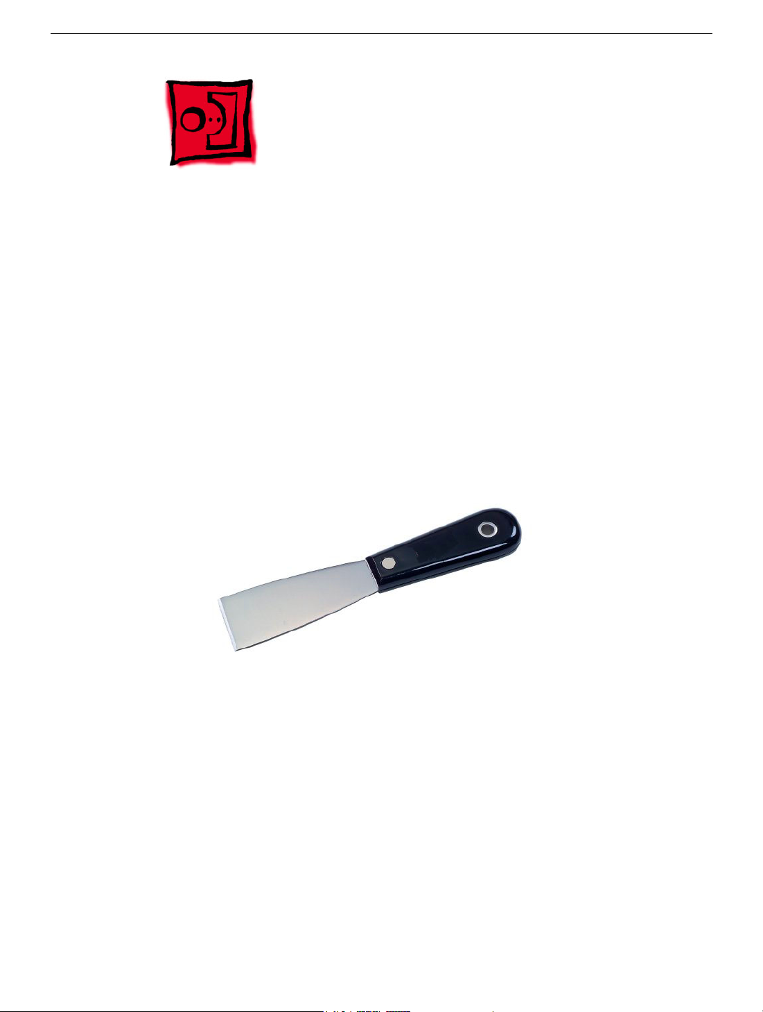
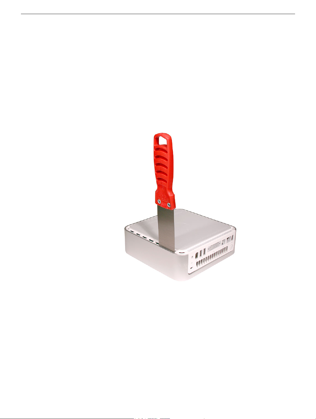
• Putty knife (922-6761),1.5 inch (38 mm), flexible blade
General Information
Mac mini Take Apart -
1
Page 5
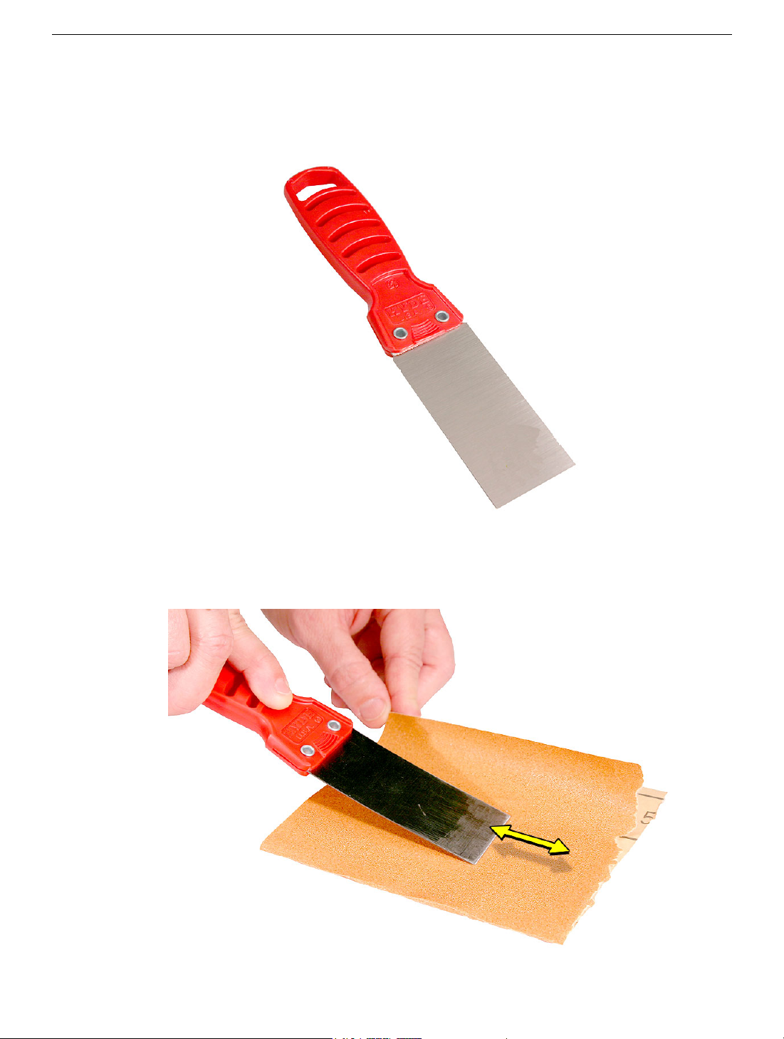
Modify the Putty Knife
1. If you don’t order a modified putty knife (922-6761) from Apple Service, purchase a
putty knife with a 1.5-inch (38 mm), flexible metal blade.
2. Using sandpaper (150 grit), file down the end of the putty knife (on one side) until it’s
slightly beveled. Rub the edge of the putty knife back and forth for about 2 minutes on
the sandpaper.
2 -
Mac mini Take Apart
General Information
Page 6
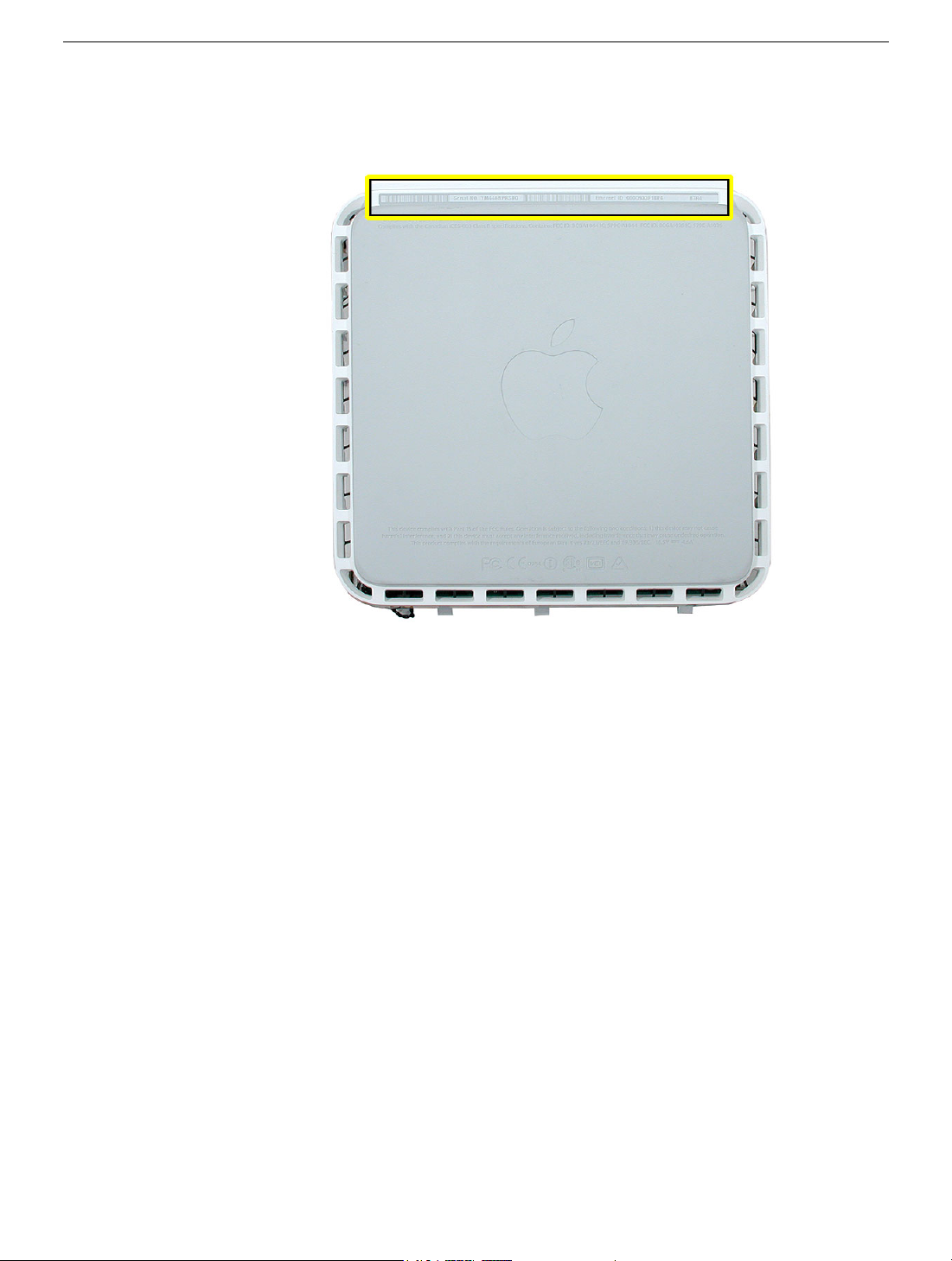
Serial Number Location
The product serial number and Ethernet ID are located on the bottom housing.
General Information
Mac mini Take Apart -
3
Page 7
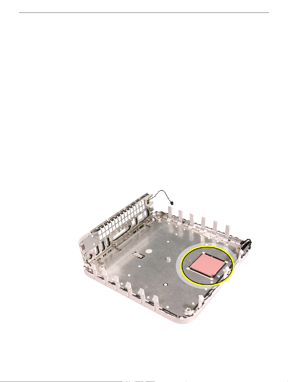
Thermal Pad
The thermal pad is located on the bottom housing. A new thermal pad is included with the
logic board and the bottom housing, and the pads can be ordered separately as a kit (part
number 922-6749).
Replace the pad when:
• the logic board or the bottom housing is replaced
• the pad is torn, withered, or damaged
Important:
thermal pad with a new identical pad.
Never use thermal paste in place of the thermal pad. You must replace the
Procedure
1. Remove the original pad from the bottom housing or the logic board using a black stick
or other nonconductive nylon tool.
2. Remove the protective backing on the new thermal pad.
contact with either side of the thermal pad as dirt and body oils reduce the thermal
pad's conductivity.
3. Place the new thermal pad on the bottom housing (as shown). Make sure the thermal
pad has even contact with the bottom housing. There should be no air pockets.
Note:
Avoid unnecessary
4 -
Mac mini Take Apart
4. Replace the logic board.
General Information
Page 8

Top Housing
Tools
The only tool required for this procedure is a modified putty knife (part number 922-6761)
Preliminary Steps
1. Shut down the computer.
Warning:
internal components or the components you are installing. Do not open the computer
or attempt to install items inside it while it is on.
2. Unplug all external cables from the computer except the power cord.
3. Touch the metal case to discharge any static electricity from your body.
Important:
components inside the computer. To avoid generating static electricity, do not walk
around the room until you have finished working and closed the computer.
4. Unplug the power cord.
5. Put on an ESD wrist strap.
Always shut down the computer before opening it to avoid damaging its
Always discharge static before you touch any parts or install any
Top Housing
Mac mini Take Apart -
5
Page 9
Removal Procedure
Caution:
1. Place the computer on a clean, flat surface.
2. Turn the computer over so the ports are facing you and the bottom of the computer
3. Hold the putty knife with the beveled edge facing the bottom housing. Insert the tool
To avoid scratching the case, use caution when using the putty knife.
(gray color) is facing up.
into the gap where the metal housing and the bottom assembly come together on the
left side of the computer.
top or bottom housing when inserting the tool
Important:
Be extremely careful not to scratch or dent the
6 -
Mac mini Take Apart
Top Housing
Page 10
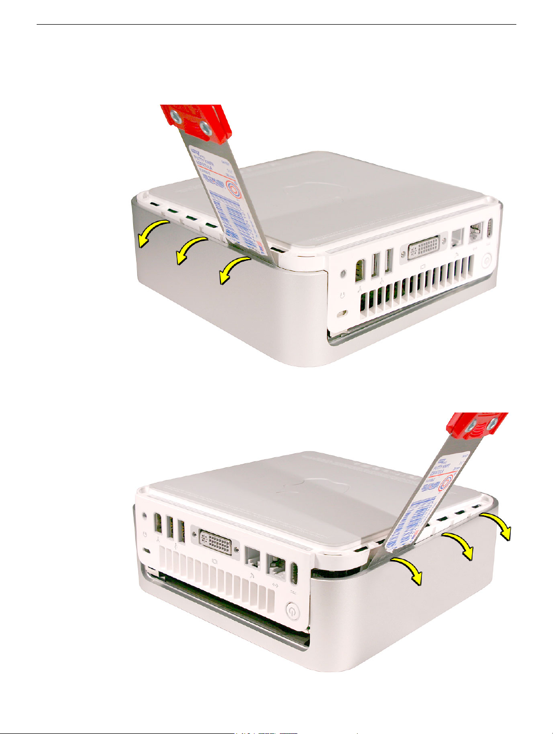
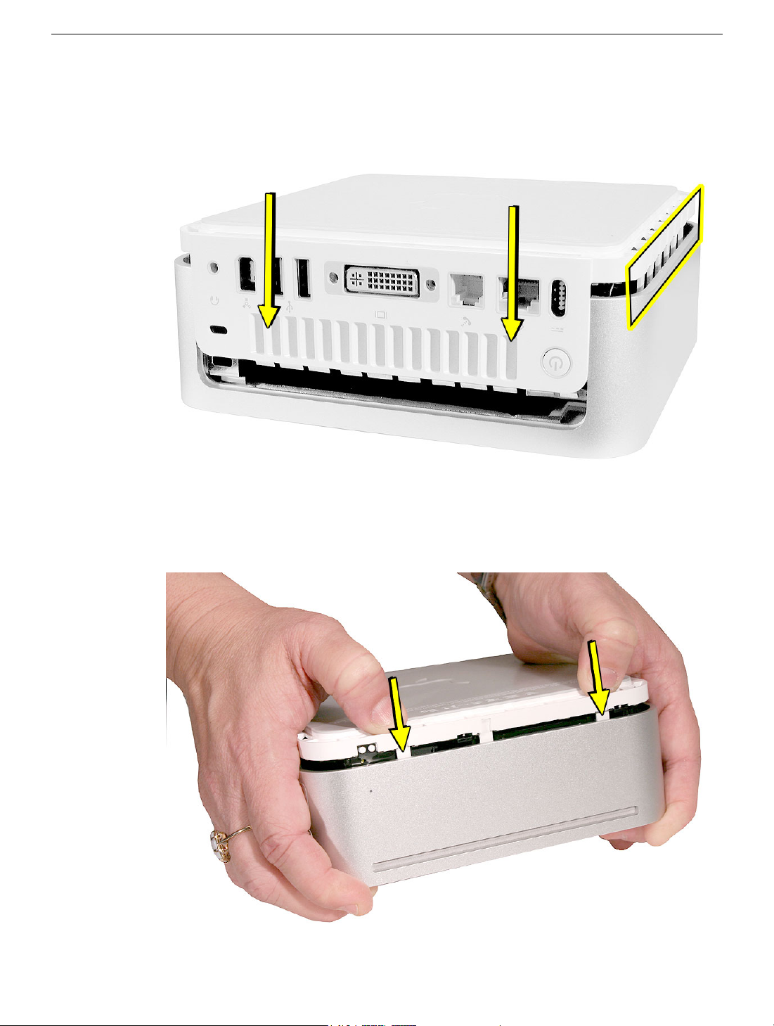
4. Gently release the internal latches by prying the tool away from the computer.
Note:
You will hear little popping sounds as the latches release and the bottom
moves away from the top housing, creating a gap at the top of the I/O panel.
5. Repeat the procedure on the right side of the unit.
Top Housing
Mac mini Take Apart -
7
Page 11
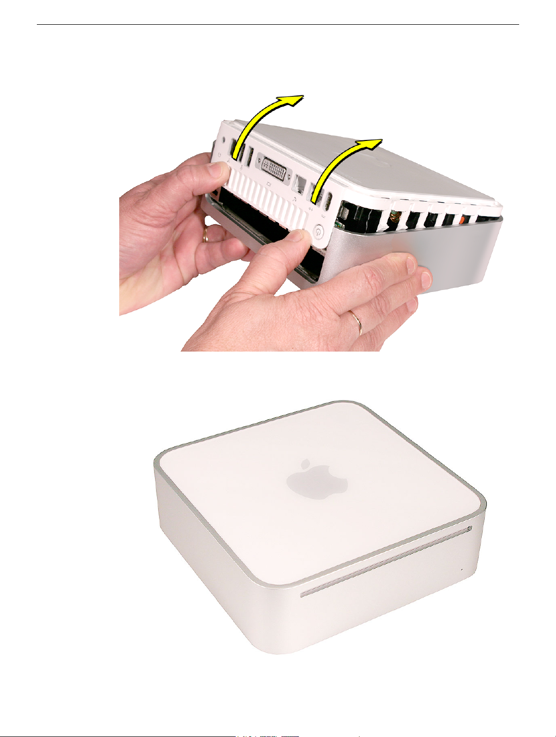
6. Push the I/O panel upward until the top housing is removed. The popping sounds will
continue as you push the I/O panel; this is normal.
7. Set the top housing aside.
8 -
Mac mini Take Apart
Top Housing
Page 12
Replacement Procedure
1. Align the rear I/O panel with the top housing. Make sure all the white latches on the
sides of the unit are aligned as shown in the photo below
2. Squeeze the unit together firmly as shown.
Top Housing
Mac mini Take Apart -
9
Page 13
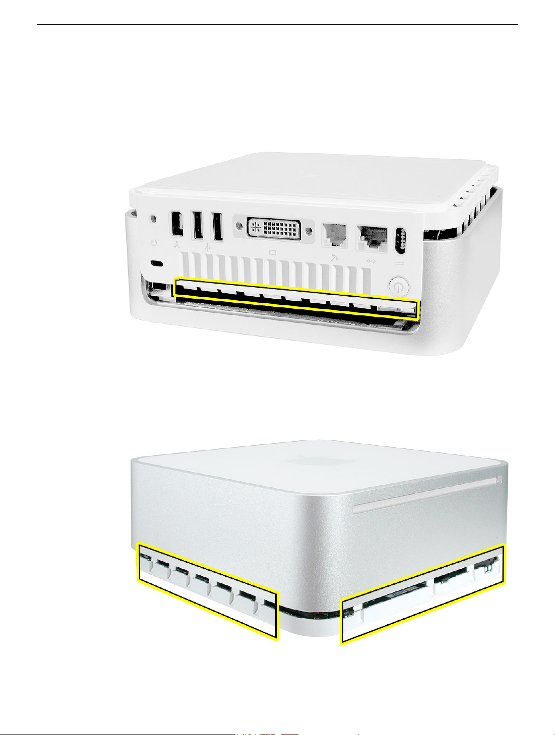
3. If the computer doesn’t go together, check the EMI tab alignment and try again. Check
that the metal tabs aren’t bent.
Work your hands around the unit squeezing the top and bottom until they snap
together and there are no gaps.
10 -
Mac mini Take Apart
Top Housing
Page 14
AirPort Antenna and AirPort Extreme Card
Tools
This procedure requires the following tools:
• Black stick (or other nonconductive nylon or plastic tool)
• Jeweler’s #0 Phillips screwdriver
• Kapton tape
Preliminary Steps
Before you begin, remove the top housing.
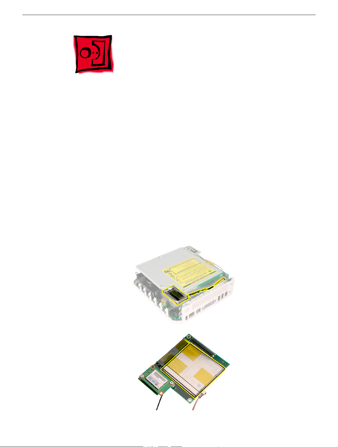
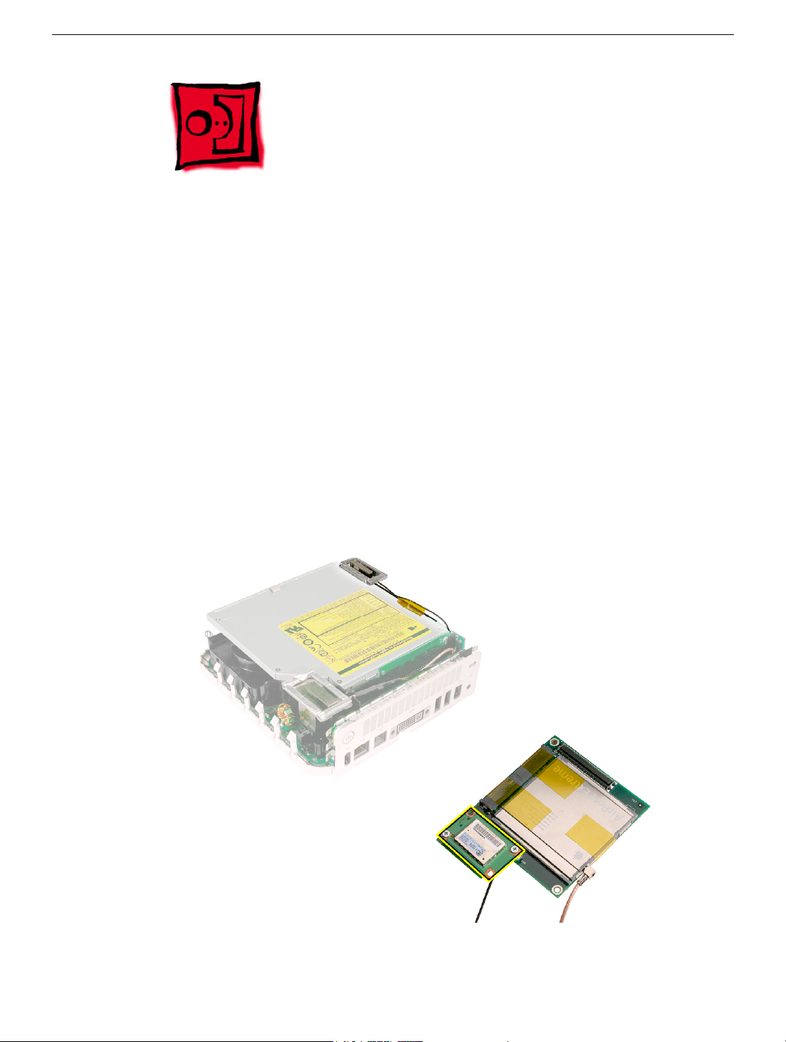
Part Location
AirPort Antenna and AirPort Extreme Card
Mac mini Take Apart -
11
Page 15
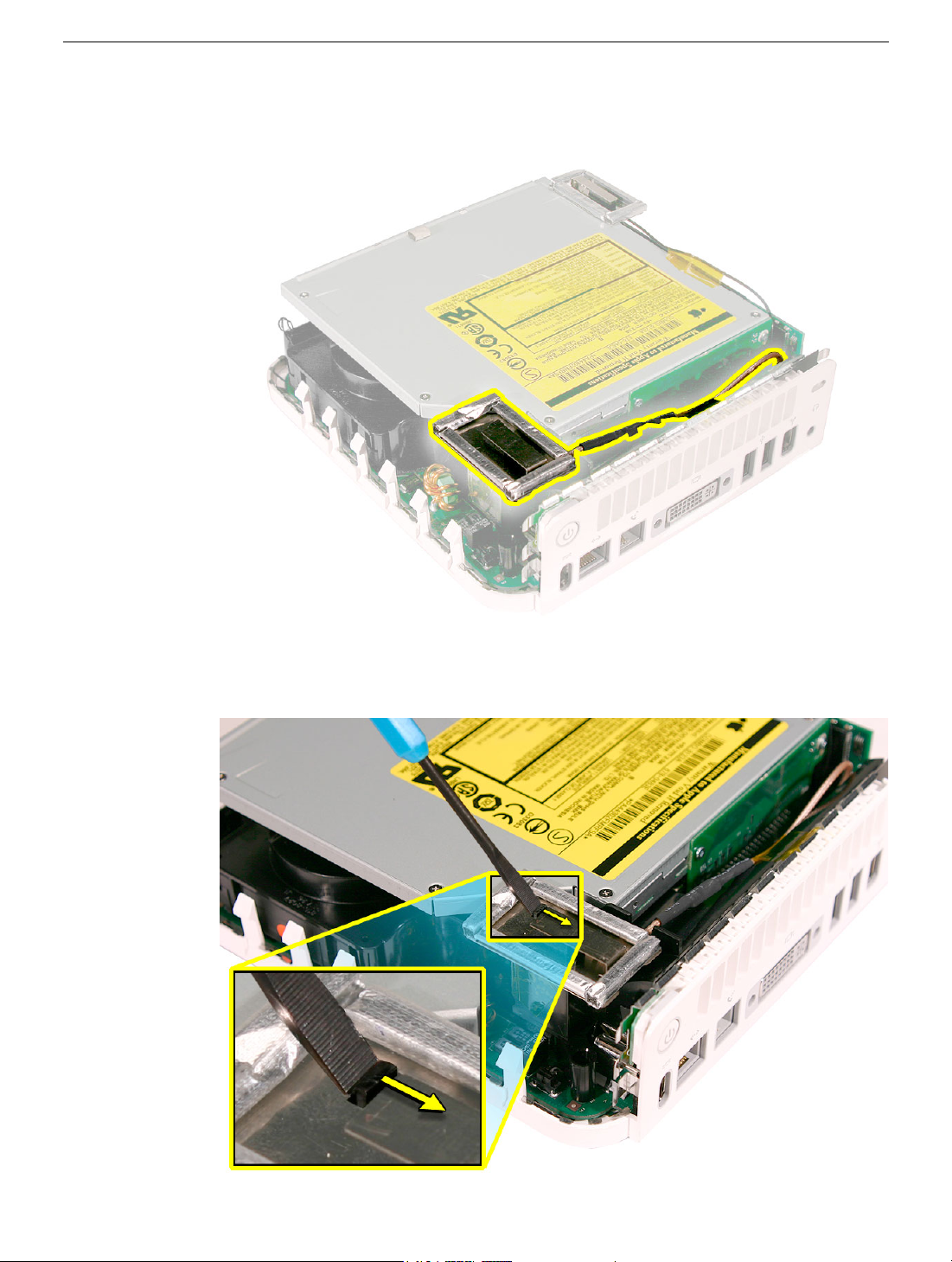
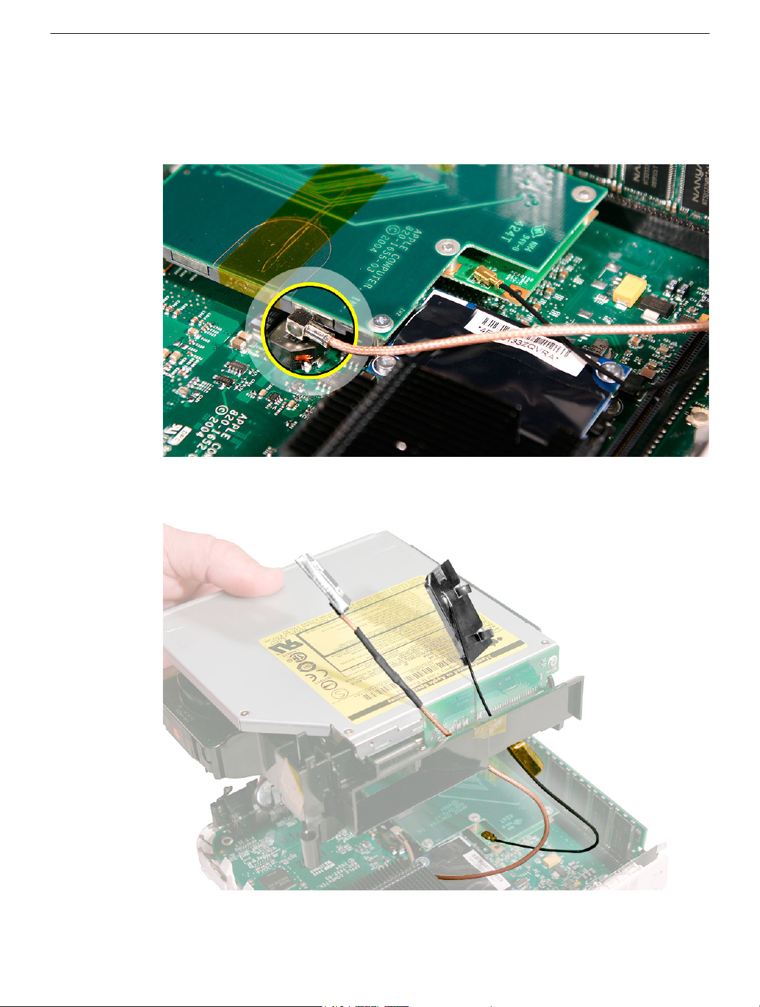
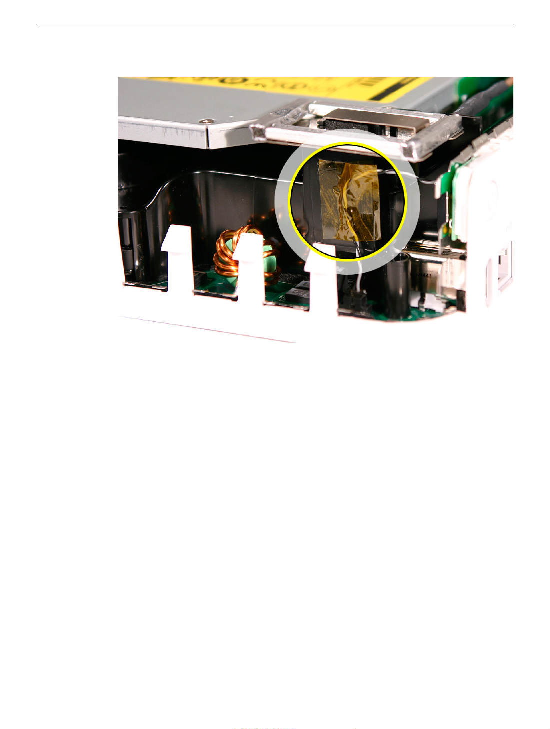
Removal Procedure
1. Locate the AirPort antenna.
2. Using a black stick, push the black latch (see inset) toward the I/O ports to release the
antenna from the internal frame.
12 -
Mac mini Take Apart
AirPort Antenna and AirPort Extreme Card
Page 16
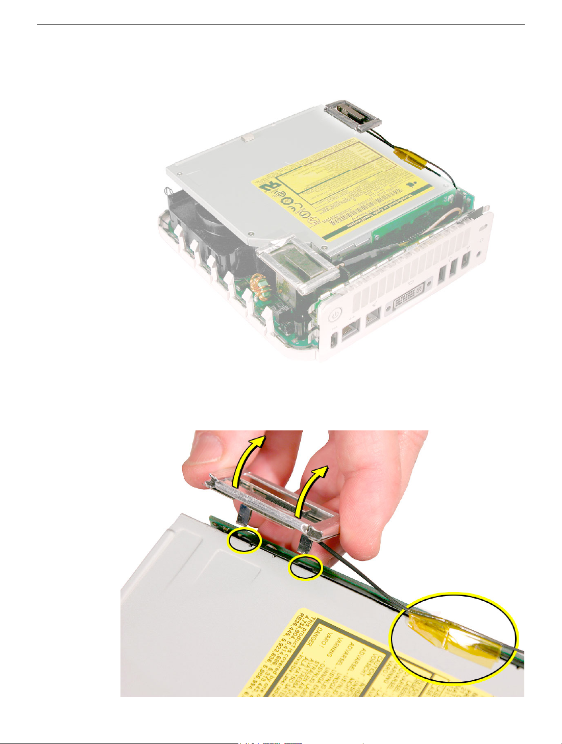
4. Carefully lift the antenna up and off the internal frame. Free the antenna from the
kapton tape (circled).
warped antenna will affect AirPort connectivity.
Important:
Take care handling the AirPort antenna as a bent or
5. Set the AirPort antenna off to the side.
cable are connected to the mezzanine board located under the internal frame.
Note:
The AirPort Extreme card and antenna
AirPort Antenna and AirPort Extreme Card
Mac mini Take Apart -
13
Page 17
6. Locate the Bluetooth antenna.
7. Pull the Bluetooth antenna up and out of the openings on the plastic rail. Free the
antenna cable from the kapton tape.
antenna as a bent or warped antenna will affect Bluetooth connectivity.
Important:
Take care handling the Bluetooth
14 -
Mac mini Take Apart
AirPort Antenna and AirPort Extreme Card
Page 18
8. Set the Bluetooth antenna off to the side and out of the way.
board is connected to the mezzanine board located under the internal frame.
Note:
The Bluetooth
9. Free the power button cable from the kapton tape on the internal frame.
AirPort Antenna and AirPort Extreme Card
Mac mini Take Apart -
15
Page 19
10. With a jeweler’s # 0 Phillips screwdriver, remove 3 screws on the internal frame.
11. Lift the internal frame straight up.
16 -
Mac mini Take Apart
AirPort Antenna and AirPort Extreme Card
Page 20
12. Gently guide the Bluetooth and Airport antenna cables down through the opening in
the internal frame.
13. Set the internal frame aside.
AirPort Antenna and AirPort Extreme Card
Mac mini Take Apart -
17
Page 21
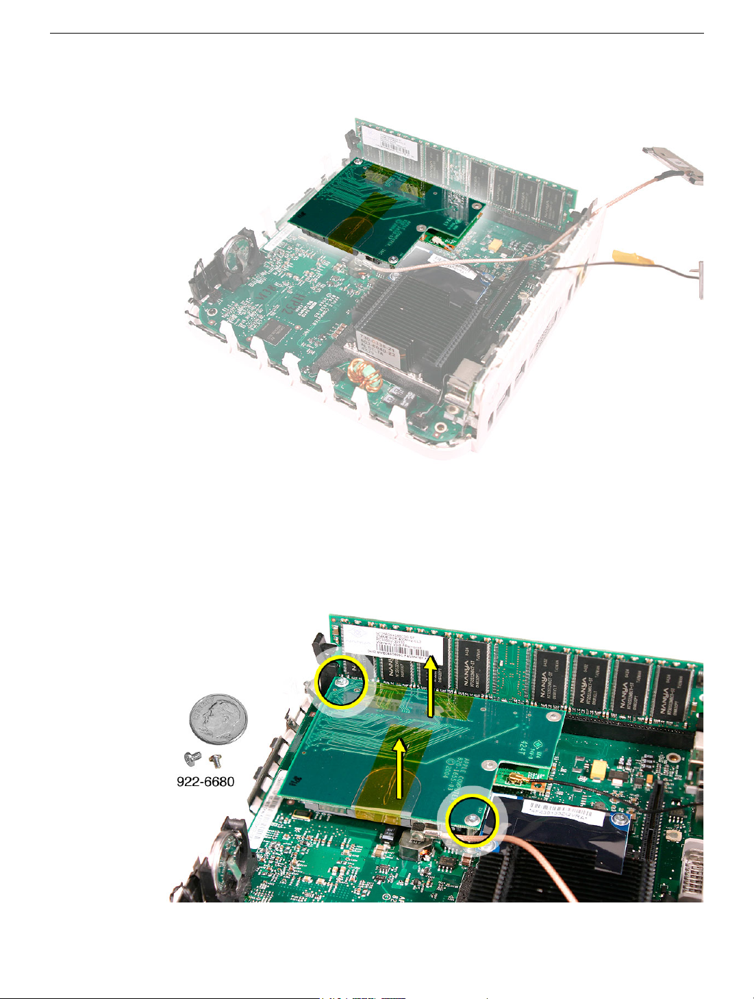
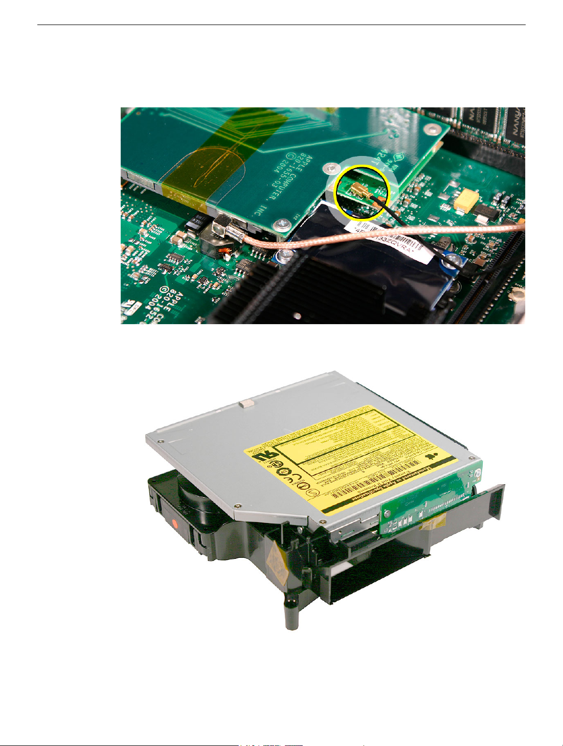
14. Locate the mezzanine board on the logic board.
15. To access the AirPort Extreme card remove the two screws on the mezzanine board
with a jeweler’s # 0 Phillips screwdriver. Pull the mezzanine board straight up and off
the logic board connector.
18 -
Mac mini Take Apart
AirPort Antenna and AirPort Extreme Card
Page 22
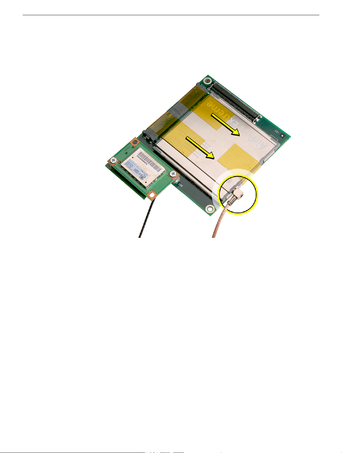
16. Turn over the mezzanine board. With your fingernail or black stick, remove the AirPort
antenna cable (circled) from the AirPort Extreme card. Remove the kapton tape that
secures the card to the mezzanine board. Pull the AirPort Extreme card out of the
connector on the mezzanine board.
AirPort Antenna and AirPort Extreme Card
Mac mini Take Apart -
19
Page 23
Replacement Procedure
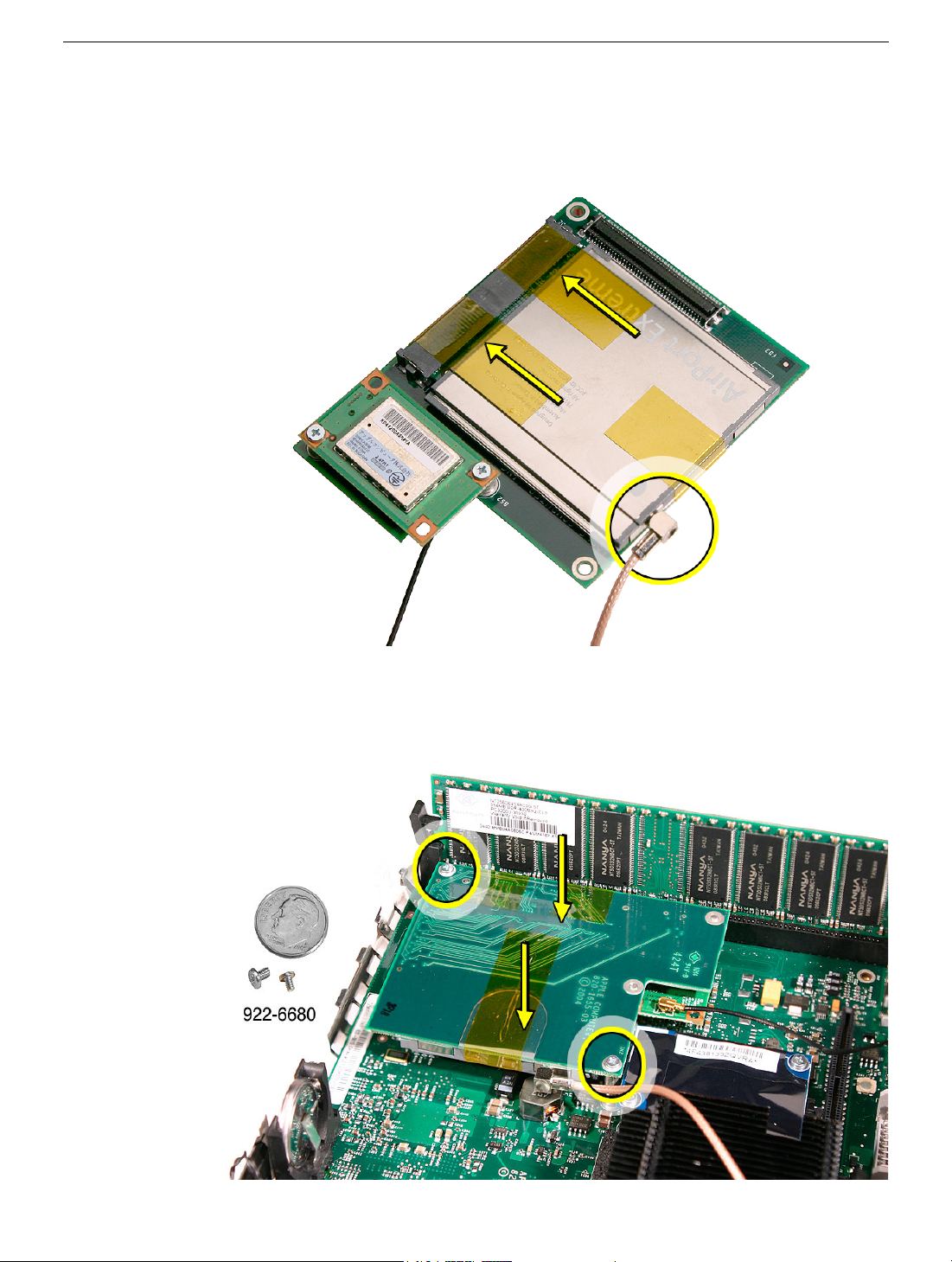
1. Install the AirPort Extreme card into the connector on the mezzanine board and
replace the kapton tape as shown. Plug the AirPort antenna cable into the opening on
the end of the AirPort Extreme card.
2. Turn over the mezzanine board so the AirPort Extreme card is facing down. Connect
the mezzanine board to the connector on the logic board. Replace the two screws on
the mezzanine board.
20 -
Mac mini Take Apart
AirPort Antenna and AirPort Extreme Card
Page 24
3. Make sure that the AirPort antenna cable is firmly inserted into the AirPort Extreme
card. If the connector is not fully inserted, you’ll see a large portion of the connector
collar. For details see Knowledge Base article 108039, “Properly attaching the
antenna on an AirPort Extreme card.”
4. Hold the internal frame over the logic board as shown. Route the AirPort and
Bluetooth antenna cables up through the opening in the internal frame.
AirPort Antenna and AirPort Extreme Card
Mac mini Take Apart -
21
Page 25
5. Lower the internal frame into place.
6. Route the antenna cables to the right side of the interconnect board on the internal
frame as you continue lowering the internal frame onto the logic board.
22 -
Mac mini Take Apart
AirPort Antenna and AirPort Extreme Card
Page 26
7. Replace the three screws on the internal frame.
8. Replace the Bluetooth antenna. Secure the antenna cable with kapton tape.
Important:
will affect Bluetooth connectivity.
Take care handling the Bluetooth antenna as a bent or warped antenna
AirPort Antenna and AirPort Extreme Card
Mac mini Take Apart -
23
Page 27
9. Replace the AirPort Extreme antenna. Secure the cable with kapton tape.
Important:
will affect AirPort connectivity.
Take care handling the AirPort antenna as a bent or warped antenna
10. Gently fasten the antenna onto the internal frame. The antenna is held in place by the
black clip and black post (shown below).
24 -
Mac mini Take Apart
AirPort Antenna and AirPort Extreme Card
Page 28
11. Secure the power button cable to the internal frame with the kapton tape.
12. Replace the top housing.
AirPort Antenna and AirPort Extreme Card
Mac mini Take Apart -
25
Page 29
Bluetooth Antenna and Bluetooth Board
Tools
This procedure requires the following tools:
• Black stick (or other nonconductive nylon or plastic tool)
• Jeweler’s #0 Phillips screwdriver
• Kapton tape
Preliminary Steps
Before you begin, remove the top housing.
Part Location
26 -
Mac mini Take Apart
Bluetooth Antenna and Bluetooth Board
Page 30
Removal Procedure
1. Locate the Bluetooth antenna.
2. Pull the Bluetooth antenna up and out of the openings on the plastic rail. Free the
antenna cable from the kapton tape.
antenna as a bent or warped antenna will affect Bluetooth connectivity.
Important:
Take care handling the Bluetooth
Bluetooth Antenna and Bluetooth Board
Mac mini Take Apart -
27
Page 31

3. Set the Bluetooth antenna off to the side and out of the way.
board is connected to the mezzanine board located under the internal frame.
Note:
The Bluetooth
4. Locate the AirPort antenna.
28 -
Mac mini Take Apart
Bluetooth Antenna and Bluetooth Board
Page 32

5. Using the black stick push the black latch (see inset) toward the I/O ports to release
the antenna from the internal frame.
4. Carefully lift the antenna up and off the internal frame. Free the antenna from the
kapton tape (circled).
warped antenna will affect AirPort connectivity.
Important:
Take care handling the AirPort antenna as a bent or
Bluetooth Antenna and Bluetooth Board
Mac mini Take Apart -
29
Page 33

5. Set the AirPort antenna off to the side.
cable are connected to the mezzanine board located under the internal frame.
Note:
The AirPort Extreme card and antenna
6. Free the power button cable from the kapton tape on the internal frame.
30 -
Mac mini Take Apart
Bluetooth Antenna and Bluetooth Board
Page 34

7. With a jeweler’s #0 Phillips screwdriver, remove 3 screws on the internal frame.
8. Lift the internal frame straight up.
Bluetooth Antenna and Bluetooth Board
Mac mini Take Apart -
31
Page 35

9. Gently guide the Bluetooth and Airport antenna cables through the opening in the
frame.
10. Set the internal frame aside.
32 -
Mac mini Take Apart
Bluetooth Antenna and Bluetooth Board
Page 36

11. Locate the mezzanine board on the logic board.
12. With your fingernail disconnect the Bluetooth antenna cable from the Bluetooth board.
Bluetooth Antenna and Bluetooth Board
Mac mini Take Apart -
33
Page 37

13. Remove the two screws on the mezzanine board. Lift the mezzanine board straight up
and off the logic board connector.
to the mezzanine board. Remove the AirPort antenna cable if required to perform the
repair.
Caution:
The AirPort antenna cable is still attached
14. Turn over the mezzanine board. With a jeweler’s #0 Phillips screwdriver remove the
two screws on the Bluetooth board. Pull the Bluetooth board off the connector on the
mezzanine board.
34 -
Mac mini Take Apart
Bluetooth Antenna and Bluetooth Board
Page 38

Replacement Procedure
1. Install the Bluetooth board onto tthe mezzanine board. With a jeweler’s #0 Phillips
screwdriver replace the two screws.
2. Connect the mezzanine board to the logic board. With a jeweler’s #0 Phillips
screwdriver replace the two mezzanine board screws.
Bluetooth Antenna and Bluetooth Board
Mac mini Take Apart -
35
Page 39
3. Connect the Bluetooth antenna cable to the Bluetooth board. Press the cable firmly
onto the Bluetooth board, until it clicks into place.
connected before installing the mezzanine board.
4. Locate the internal frame.
Note:
The Bluetooth antenna can be
36 -
Mac mini Take Apart
Bluetooth Antenna and Bluetooth Board
Page 40

5. Hold the internal frame over the logic board as shown. Route the AirPort and
Bluetooth antenna cables through the opening in the internal frame.
6. Lower the internal frame into place.
Bluetooth Antenna and Bluetooth Board
Mac mini Take Apart -
37
Page 41

7. Route the antenna cables to the right side of the interconnect board on the internal
frame. Lower the internal frame onto the logic board.
8. Replace the three screws on the internal frame.
38 -
Mac mini Take Apart
Bluetooth Antenna and Bluetooth Board
Page 42

9. Replace the Bluetooth antenna and secure the antenna cable with kapton tape.
Important: Take care handling the Bluetooth antenna as a bent or warped antenna
will affect Bluetooth connectivity.
10. Replace the AirPort Extreme antenna and secure the cable with kapton tape.
Important: Take care handling the AirPort antenna as a bent or warped antenna will
affect AirPort connectivity
Bluetooth Antenna and Bluetooth Board
Mac mini Take Apart - 39
Page 43

11. Gently fasten the antenna onto the internal frame. The antenna is held in place by the
black clip and black post (shown below).
12. Secure the power button cable to the internal frame with the kapton tape.
13. Replace the top housing.
40 - Mac mini Take Apart
Bluetooth Antenna and Bluetooth Board
Page 44
Internal Frame
Tools
The only tool required for this procedure is a Phillips #0 screwdriver.
Preliminary Steps
Before you begin, remove the top housing.
Part Location
Internal Frame
Mac mini Take Apart - 41
Page 45

Removal Procedure
1. Free the power button cable from the kapton tape on the internal frame.
2. Locate the Bluetooth antenna.
42 - Mac mini Take Apart
Internal Frame
Page 46

3. Pull the Bluetooth antenna up and out of the openings on the plastic rail. Free the
antenna cable from the kapton tape. Important: Take care handling the Bluetooth
antenna as a bent or warped antenna will affect Bluetooth connectivity.
4. Set the Bluetooth antenna off to the side and out of the way. Note: The Bluetooth
board and antenna cable are connected to the mezzanine board located under the
internal frame.
Internal Frame
Mac mini Take Apart - 43
Page 47

5. Locate the AirPort antenna.
6. Using the black stick push the black latch (see inset) toward the I/O ports to release
the antenna from the internal frame.
44 - Mac mini Take Apart
Internal Frame
Page 48

4. Carefully lift the antenna off the frame. Free the antenna from the kapton tape
(circled). Important: Take care handling the AirPort antenna as a bent or warped
antenna will affect AirPort connectivity
5. Set the AirPort antenna off to the side. Note: The AirPort card and antenna cable are
connected to the mezzanine board located under the internal frame.
Internal Frame
Mac mini Take Apart - 45
Page 49

6. WIth a jeweler’s # 0 Phillips screwdriver remove three screws on the internal frame.
7. Lift the internal frame straight up.
46 - Mac mini Take Apart
Internal Frame
Page 50

8. Gently guide the Bluetooth and Airport antenna cables down through the opening in
the frame. Set the antenna cables off to the side.
9. The following parts are connected to the internal frame (black plastic):
• hard drive
• optical drive
• fan
• speaker
• interconnect board
Refer to the individual take-apart procedures to remove or replace any of these parts.
Internal Frame
Mac mini Take Apart - 47
Page 51

Replacement Procedure
1. If you removed any service parts from the internal frame, replace them.
2. Hold the internal frame over the logic board as shown. Route the AirPort and
Bluetooth antenna cables up through the opening in the internal frame.
48 - Mac mini Take Apart
Internal Frame
Page 52

3. Lower the internal frame into place.
4. Route the antenna cables to the right side of the interconnect board on the internal
frame as you continue lowering the internal frame onto the logic board.
Internal Frame
Mac mini Take Apart - 49
Page 53

5. Replace the three screws on the internal frame.
6. Replace the Bluetooth antenna and secure the antenna cable with kapton tape.
Important: Take care handling the Bluetooth antenna as a bent or warped antenna
will affect Bluetooth connectivity.
50 - Mac mini Take Apart
Internal Frame
Page 54

7. Replace the AirPort Extreme antenna and secure the cable with kapton tape
Important: Take care handling the AirPort antenna as a bent or warped antenna will
affect AirPort connectivity.
8. Gently fasten the antenna onto the internal frame. The antenna is held in place by the
black clip and black post (shown below).
Internal Frame
Mac mini Take Apart - 51
Page 55

9. Secure the power button cable to the internal frame with the kapton tape.
10. Replace the top housing.
52 - Mac mini Take Apart
Internal Frame
Page 56

Hard Drive
Tools
This procedure requires the following tools:
• Phillips #2 screwdriver
• Phillips #2 screwdriver, angled
• Phillips #0 screwdriver
Preliminary Steps
Before you begin, remove the top housing and the internal frame.
Part Location
Hard Drive
Mac mini Take Apart - 53
Page 57

Removal Procedure
1. Locate the internal frame.
2. Turn over the internal frame to locate the hard drive.
54 - Mac mini Take Apart
Hard Drive
Page 58

3. With a jeweler’s #0 screwdriver remove the two fan screws.
4. Flip the fan to the left to access the hard drive screws (see next step).
Hard Drive
Mac mini Take Apart - 55
Page 59

5. Using a #2 Phillips screwdriver, remove the two hard drive screws (shown by the
dotted line) on the internal frame. You may need an angled screwdriver to access the
screw on the right. Important: Don’t remove the kapton tape from the internal frame
near the screw on the right. The hole is covered to direct airflow within the internal
frame.
4. Remove the remaining two hard drive screws and disconnect the fan and speaker
cables.
56 - Mac mini Take Apart
Hard Drive
Page 60

5. Remove the kapton tape to release the cables.
6. WIth a black stick or other nonconductive tool, pry the hard drive off the connector on
the interconnect board. Lift the hard drive out of the internal frame and set it aside.
Hard Drive
Mac mini Take Apart - 57
Page 61

Replacement Procedure
1. WIth the colored side of the hard drive face up, place the hard drive into the internal
frame and connect it to the black connector on the interconnect board.
2. Replace the kapton tape.
58 - Mac mini Take Apart
Hard Drive
Page 62

3. Replace two screws and connect the fan and speaker cables to the interconnect
board.
4. Replace the two hard drive screws on the inside of the internal frame.
Hard Drive
Mac mini Take Apart - 59
Page 63

4. Flip the fan back into the internal frame.
4. Replace the two fan screws.
60 - Mac mini Take Apart
Hard Drive
Page 64

5. Make sure the fan cables are routed and tucked under the clip as shown.
6. Turn the internal frame over
7. Replace the internal frame.
Hard Drive
8. Replace the top housing.
Mac mini Take Apart - 61
Page 65

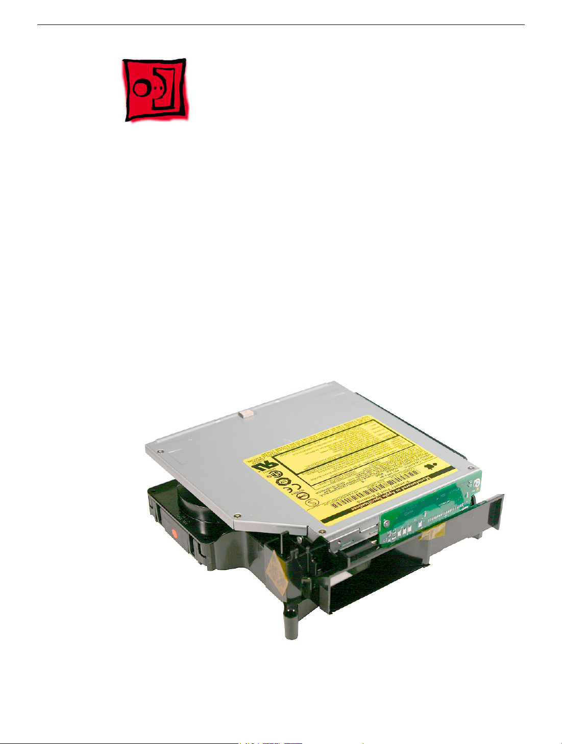
Optical Drive
Tools
This procedure requires the following tools:
• Black stick (or other nonconductive nylon or plastic tool)
• Jeweler’s #0 Phillips screwdriver
Preliminary Steps
Before you begin remove the following:
• Top housing
• AirPort antenna (if present)
• Bluetooth antenna (if present)
Part Location
62 - Mac mini Take Apart
Optical Drive
Page 66

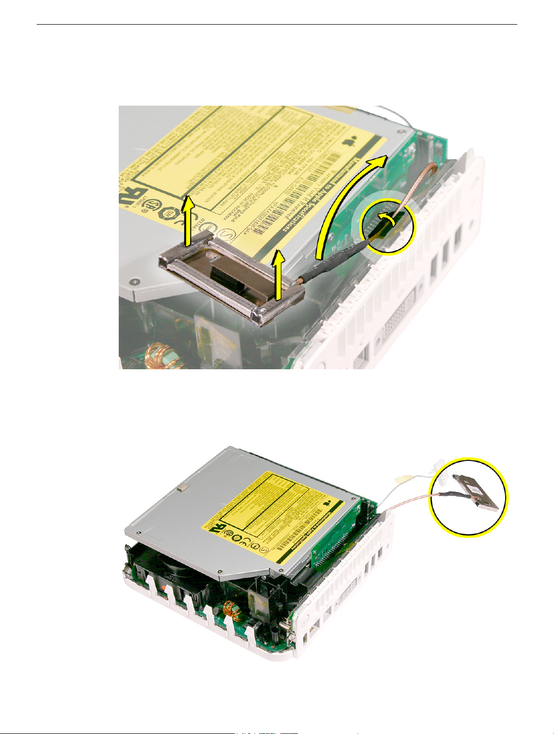
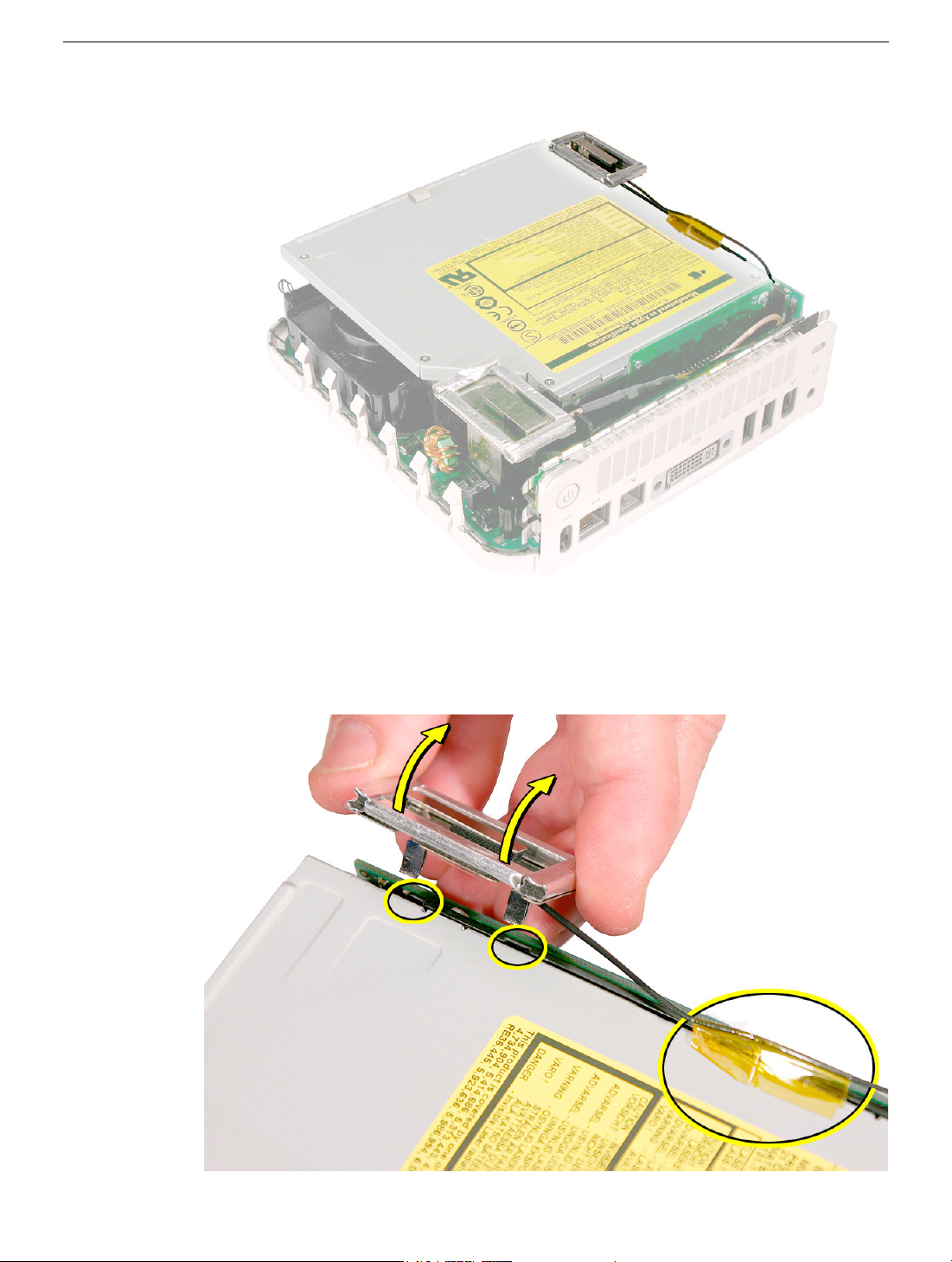
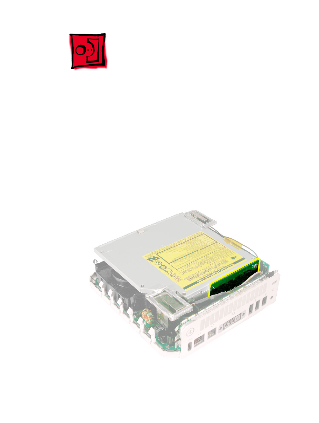
Removal Procedure
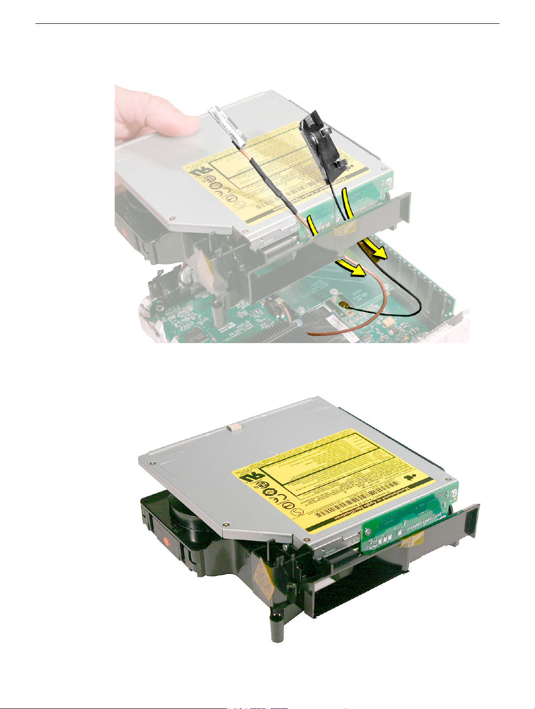
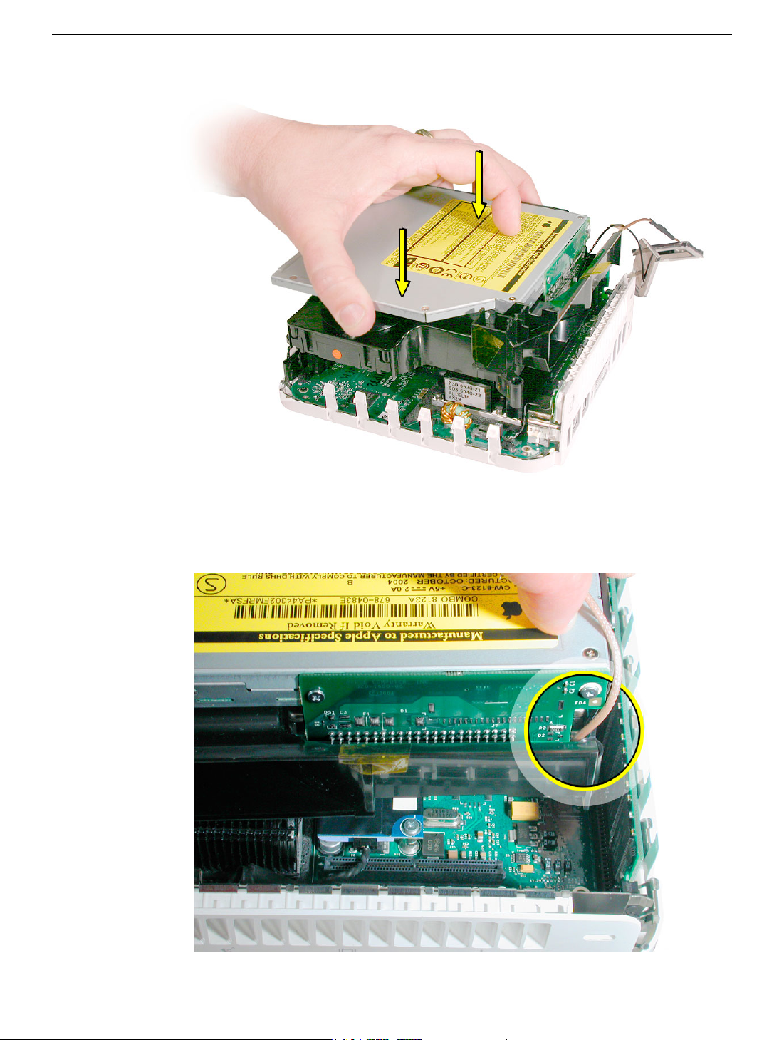
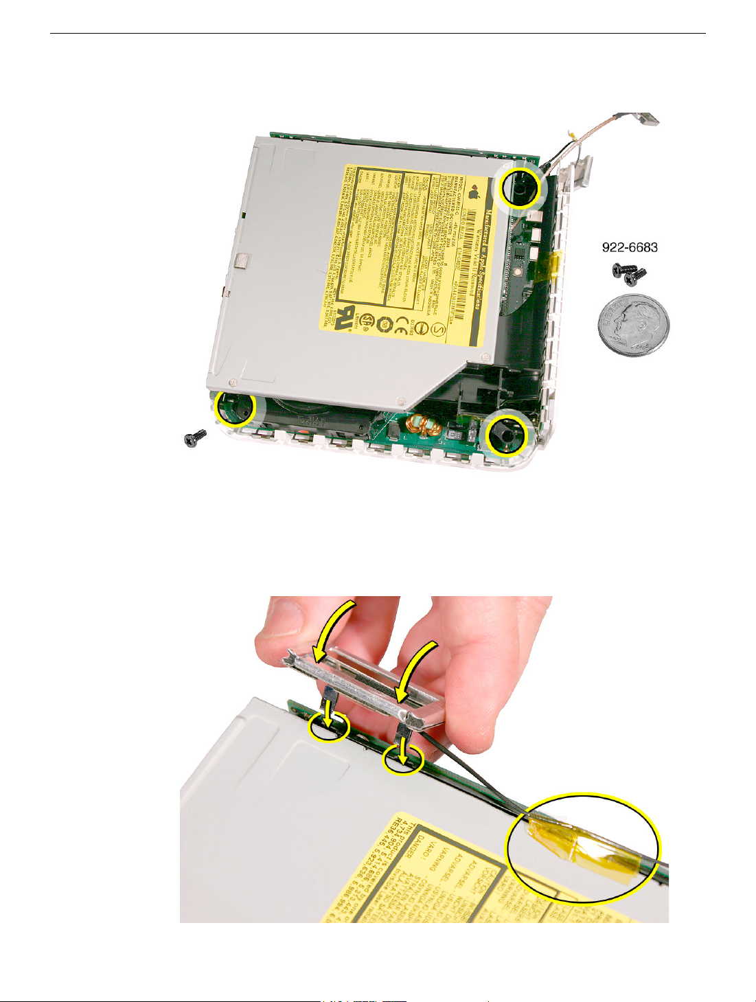
1. Using a jeweler’s #0 Phillips screwdriver, remove the four optical drive screws and the
two interconnect board screws.
2. Using a black stick, pry the optical drive off the interconnect board (#1) and slide the
optical drive (#2) off the internal frame.
Optical Drive
Mac mini Take Apart - 63
Page 67

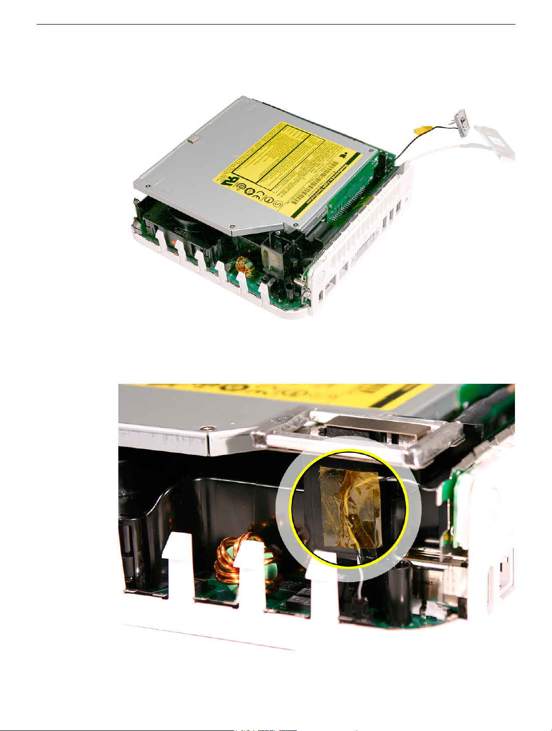
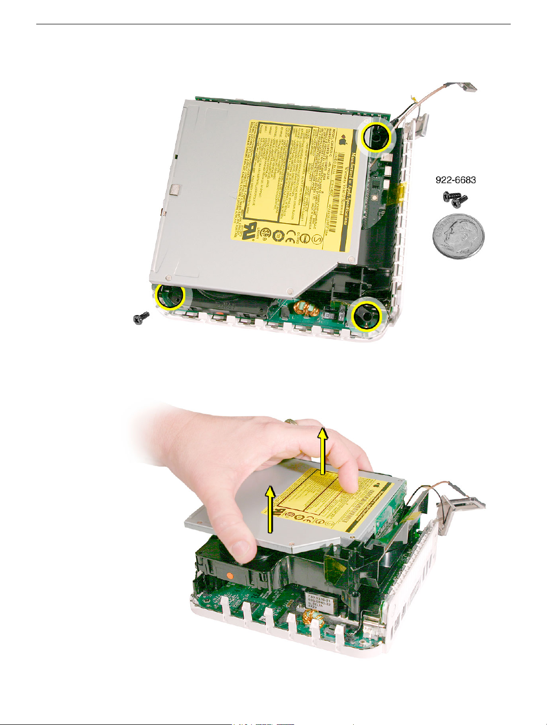
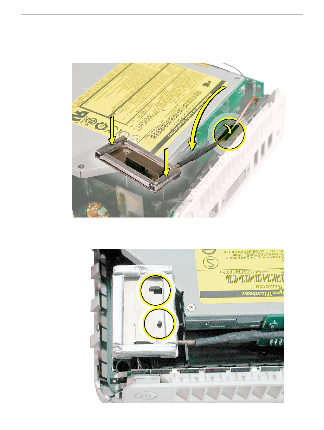
Replacement Procedure
1. Connect the optical drive to the interconnect board and replace the two interconnect
board screws.
4. Replace the four optical drive screws.
64 - Mac mini Take Apart
Optical Drive
Page 68

5. Replace the Bluetooth antenna (if present).
6. Replace the AirPort antenna (if present).
7. Replace the top housing.
Optical Drive
Mac mini Take Apart - 65
Page 69

Fan
Tools
The only tool required for this procedure is a jeweler’s #0 Phillips screwdriver.
Preliminary Steps
Before you begin, remove the top housing and the internal frame.
Part Location
Note: The fan is located under the optical drive.
.
66 - Mac mini Take Apart
Fan
Page 70

Removal Procedure
1. Turn over the internal frame to locate the fan. Remove the two fan screws with a
jeweler’s #0 Phillips screwdriver.
2. Free the fan cable from the clip on the internal frame.
Fan
Mac mini Take Apart - 67
Page 71

4. Remove the tape securing the fan and speaker cables.
4. Free the fan cable (top cable) from another clip on the inside of the internal frame.
68 - Mac mini Take Apart
Fan
Page 72

4. Disconnect the fan cable (on the right) from the interconnect board.
4. Lift the fan out of the internal frame.
Fan
Mac mini Take Apart - 69
Page 73

Replacement Procedure
1. Place the fan in the internal frame.
2. Replace two fan screws, the kapton tape, and connect the fan cable (on the right) to
the interconnect board.
3. Route the fan cable through the clip on the inside of the internal frame.
70 - Mac mini Take Apart
Fan
Page 74

4. Route the fan cable under the clip on the outside of the internal frame.
5. Turn over the internal frame.
Fan
6. Replace the internal frame.
7. Replace the top housing.
Mac mini Take Apart - 71
Page 75
Interconnect Board
Tools Required
This procedure requires the following tools:
• Jeweler’s #0 Phillips screwdriver
• Black stick or nonconductive tool
Preliminary Steps
Before you begin, remove the top housing and the internal frame.
Part Location
72 - Mac mini Take Apart
Interconnect Board
Page 76

Removal Procedure
1. Locate the interconnect board. Using a a jeweler’s #0 Phillips screwdriver, remove the
two screws.
2. Turn over the internal frame. Disconnect the speaker cable (on the left) and fan cable
(on the right) from the interconnect board.
Interconnect Board
Mac mini Take Apart - 73
Page 77

3. WIth a black stick or other nonconductive tool, slightly pry the interconnect board off
hard drive pins. With your fingers wiggle the interconnect board off the hard drive pins.
Caution: Be careful not to bend the hard drive pins.
74 - Mac mini Take Apart
Interconnect Board
Page 78

Replacement Procedure
1. WIth the gold pins on the interconnect board facing up, press the interconnect board
onto the hard drive and optical drive connectors. Replace the optical drive screws
(circled). Caution: Be careful not to bend the hard drive pins when connecting the
interconnect board.
2. Connect the speaker cable (on the left) and fan cable (on the right) to the interconnect
board.
Interconnect Board
Mac mini Take Apart - 75
Page 79

3. Turn over the internal frame.
4. Replace the internal frame.
5. Replace the top housing.
76 - Mac mini Take Apart
Interconnect Board
Page 80

Memory
Tools
The only tool required for this procedure is a Jeweler’s #0 Phillips screwdriver.
Preliminary Steps
Before you begin, remove the top housing.
Part Location
Memory
Mac mini Take Apart - 77
Page 81

Removal Procedure
1. Remove the Bluetooth antenna and the kapton tape. Important: Take care handling
the Bluetooth antenna as a bent or warped antenna will affect Bluetooth connectivity.
Set the antenna off to the side.
2. To release the memory from its slot, push down on the two side latches. Then pull the
memory module out of the slot. Caution: Be careful that the latch on the left doesn’t
damage the EMI clip near the I/O port.
78 - Mac mini Take Apart
Memory
Page 82

Replacement Procedure
1. Replace the memory module by lining up the notch on the module with the notch on
the slot.
2. Press firmly on the memory module until it clicks into place. Use your thumb and index
finger to push the module into the slot. The clips will secure the memory in place.
3. Replace the Bluetooth antenna and kapton tape. Important: Take care handling the
Bluetooth antenna as a bent or warped antenna will affect Bluetooth connectivity
Memory
4. Replace the top housing.
Mac mini Take Apart - 79
Page 83

Mezzanine Board
Tools
This procedure requires the following tools:
• Jeweler’s #0 Phillips screwdriver
• Black stick (or other nonconductive nylon or plastic tool)
Preliminary Steps
Before you begin, remove the top housing and the internal frame.
Part Location
80 - Mac mini Take Apart
Mezzanine Board
Page 84

Removal Procedure
Using a jeweler’s #0 Phillips screwdriver, remove the two screws from the mezzanine
board. Pull the mezzanine board straight up and off the logic board.
Mezzanine Board
Mac mini Take Apart - 81
Page 85

Replacement Procedure
1. Connect the mezzanine board to the logic board connector. Replace the two
mezzanine screws.
2. Replace the internal frame.
3. Replace the top housing.
82 - Mac mini Take Apart
Mezzanine Board
Page 86

Modem Board
Tools
This procedure requires the following tools:
• Jeweler’s #0 Phillips screwdriver
• Black stick (or other nonconductive nylon or plastic tool)
Preliminary Steps
Before you begin, remove the top housing and the internal frame.
Part Location
Modem Board
Mac mini Take Apart - 83
Page 87

Removal Procedure
1. Using a jeweler’s #0 Phillips screwdriver, remove the two screws from the modem
board.
2. Using a black stick or other nonconductive nylon or plastic tool, pry the modem board
off the logic board connector.
84 - Mac mini Take Apart
Modem Board
Page 88

3. Disconnect the RJ-11 cable from the modem board. Set the modem board aside.
Modem Board
Mac mini Take Apart - 85
Page 89

Replacement Procedure
1. Connect the RJ-11 cable to the modem board.
2. Using a jeweler’s #0 Phillips screwdriver, replace the two modem screws.
86 - Mac mini Take Apart
Modem Board
Page 90

3. Replace the internal frame.
4. Replace the top housing.
Modem Board
Mac mini Take Apart - 87
Page 91

Logic Board
Tools
This procedure requires the following tools:
• Jeweler’s #0 Phillips screwdriver
• Black stick (or other nonconductive nylon or plastic tool)
Preliminary Steps
Before you begin, remove the top housing and the internal frame.
Part Location
88 - Mac mini Take Apart
Logic Board
Page 92

Removal Procedure
1. Using a jeweler’s #0 Phillips screwdriver, remove the logic board screw. Note: The
logic board screw and the internal frame screws look similar; however, the logic board
screw is shorter than the screws used for the internal frame.
2. Disconnect the power-on cable from the connector on the logic board.
Logic Board
Mac mini Take Apart - 89
Page 93

3. Using a black stick or other nonconductive tool, disconnect the LED cable from the
connector on the logic board. Note: This connector is very small. Don’t pull on the
cable; pull on the connector.
4. After disconnecting the LED cable, gently push the LED away from the board to free
the logic board from the bottom housing. Note: Don’t bend the LED too much or it
could snap off the bottom housing.
90 - Mac mini Take Apart
Logic Board
Page 94

5. Tilt the board at an angle and pull the logic board away from the ports.
Note: If you are returning the logic board to Apple service, remove the following:
• RJ-11 connector
• memory
• mezzanine board
• modem board
For instructions, refer to the replacement procedures for these individual parts.
.
Logic Board
Mac mini Take Apart - 91
Page 95

Replacement Procedure
1. Replace the thermal pad.
Replace the thermal pad on the bottom housing whenever you replace the logic
board or the bottom housing, or if the pad is torn, withered, or damaged. For more
information, refer to the “Thermal Pad” procedure in this chapter.
2. If necessary, install the following on the logic board:
• RJ-11 connector
• modem board
• mezzanine board
• memory
For instructions, refer to the replacement procedures for these individual parts.
92 - Mac mini Take Apart
Logic Board
Page 96

3. Insert the logic board into the bottom housing. Line up the ports on the board with the
openings on the bottom housing.
4. Gently push the LED away from the board as you lower the board into the bottom
housing. Note: Don’t bend the LED too much or it could snap off the bottom housing.
Logic Board
Mac mini Take Apart - 93
Page 97

5. Connect the power-on cable to the logic board.
6. Replace the logic board screw.
94 - Mac mini Take Apart
Logic Board
Page 98

7. Replace the internal frame.
8. Replace the top housing.
Logic Board
Mac mini Take Apart - 95
Page 99

Bottom Housing
Tools
No tools are required for this procedure.
Preliminary Steps
Before you begin, remove the following:
• top housing
• internal frame
• logic board
Part Location
96 - Mac mini Take Apart
Bottom Housing
Page 100

Removal Procedure
Once the logic board is removed you are left with the bottom housing.
Bottom Housing
Mac mini Take Apart - 97
 Loading...