

Page 1

K
Service Source
LaserWriter Select
LaserWriter Select 300, LaserWriter Select 310,
LaserWriter Select 360
Page 2

K
Service Source
Basics
LaserWriter Select
Page 3
Basics Paper Path - 1
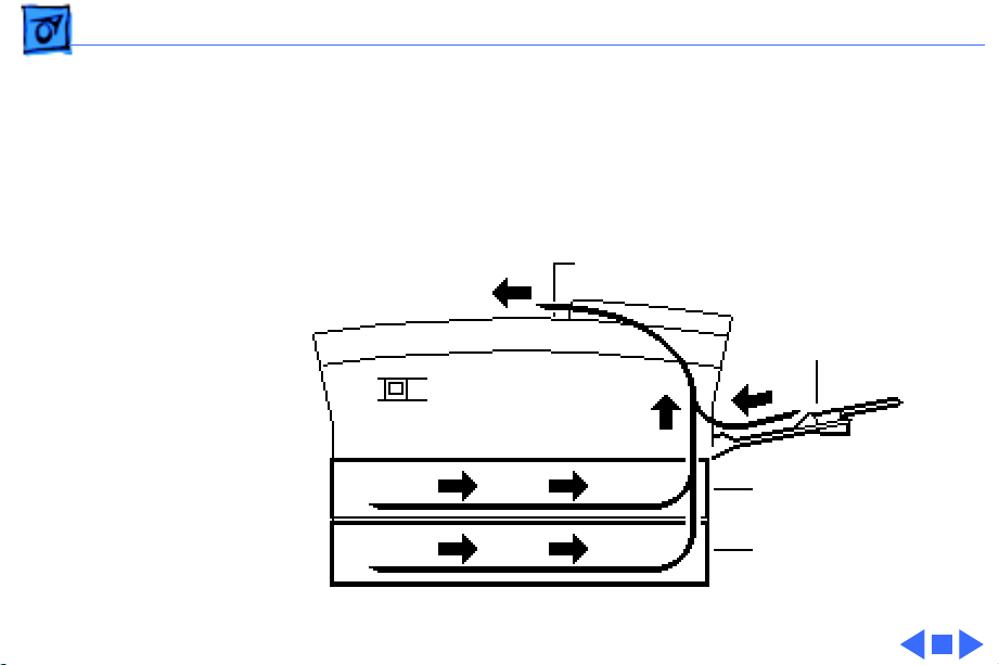
Paper Path
There are three paper sources and one output tray in a
complete system.
Output Tray
Manual Feed Tray
Standard Cassette
(250 Sheets)
Optional Sheet Feeder
(250 or 500 Sheets)
Page 4
Basics Sensing System - 2
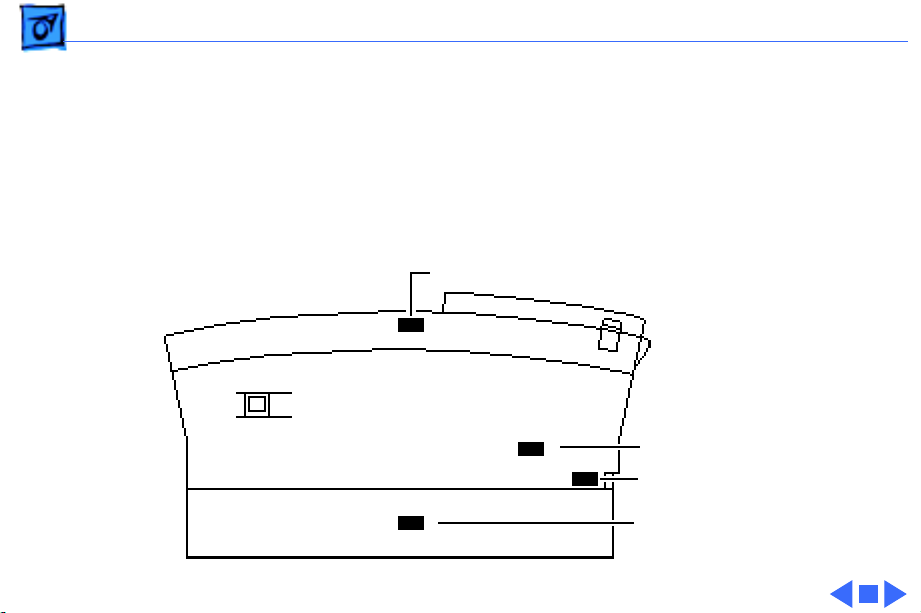
Sensing System
There are four paper sensors in the LaserWriter Select
printer. Each sensor consists of an actuator, a U-shaped
photo interrupter, and circuitry that communicates back to
the DC controller.
Paper Delivery Sensor PS201
Registration Sensor PS602
Manual Feed Sensor PS701
Paper-Out Sensor PS601
Page 5

Basics Interface Connectors - 3
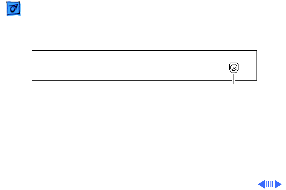
Interface Connectors
Interface connector diagrams for each of three LaserWriter
Select models are located on the following pages.
Page 6
Basics Interface Connectors - 4
LaserWriter Select 300
Mini DIN-8
Page 7
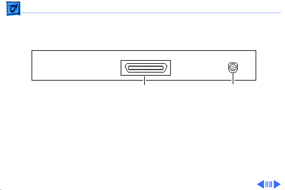
Basics Interface Connectors - 5
LaserWriter Select 310
Mini DIN-8Centronics Parallel
Page 8
Basics Interface Connectors - 6
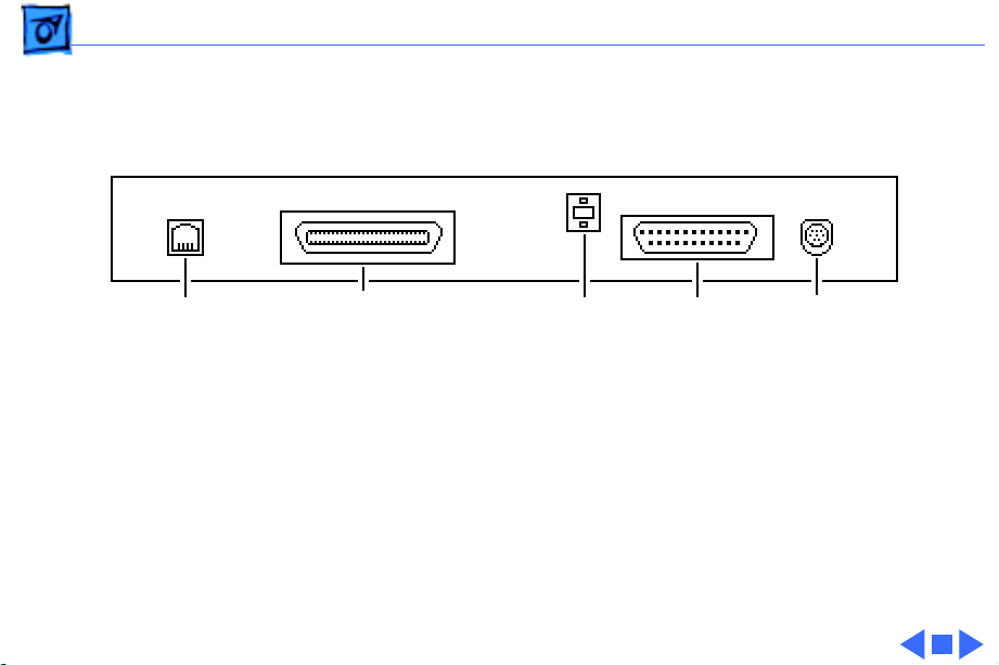
LaserWriter Select 360
RJ-11
(Optional
Fax Port)
Mini DIN-8RS-232Mode SwitchCentronics Parallel
Page 9

Basics LaserWriter Safety - 7
LaserWriter Safety
Unplug Printer
LaserWriter printers operate at high voltages. To prevent
serious injury, always switch off the printer and unplug the
AC power cord before servicing the printer.
Laser Beam Safety
Never remove the cover of the laser/optic assembly or
disconnect the beam-detect cabling when the printer is
switched on. Although the reflected laser beam is invisible,
direct exposure to it can permanently damage your eyes.
Never disassemble the laser/optical assembly, whether the
printer is powered on or not. The laser diode and focusing
lenses are factory-aligned.
Page 10

Basics LaserWriter Safety - 8
Fuser Heat
The fuser assembly rollers become very hot during printer
operation. Before servicing the fuser assembly, switch off
the printer for at least 5 minutes to allow the fuser
assembly rollers to cool.
Toner Safety
Toner is a nontoxic substance composed of plastic, iron, and
a small amount of pigment. Clean skin and clothing by
removing as much toner as possible with a dry tissue and
then washing with cold water. Hot water causes toner to jell
and permanently fuse into clothing. Toner attacks vinyl
materials, so don't allow toner to contact vinyl.
Motor Stops When Cassette is Removed
For safety purposes, the main motor on the LaserWriter
Page 11

Basics LaserWriter Safety - 9
Select 360 stops when the paper cassette is removed.
Weight
LaserWriter printers are heavy. When lifting or moving
the printer, be careful not to strain your back.
Page 12

K
Service Source
Specifications
LaserWriter Select
Page 13

Specifications General - 1
General
Engine
Printing Method
Optical System
Resolution
Imaging Languages Supported
Select 300/310: Fuji Xerox P0 engine
Select 360: Fuji Xerox P1 engine
Electrophotography using single-component dry toner
Semiconductor laser
Select 300/310: 300 dots per inch (dpi)
Select 360: 600 dpi (300 dpi in PCL mode)
Select 300: QuickDraw
Select 310: PostScript
Select 360: PostScript and HP PCL
Page 14

Specifications Intro Dates - 2
Intro Dates
Select 300/310
500-Sheet Feeder
Select 360
February 1993
August 1993
October 1993
Page 15

Specifications Logic Board - 3
Logic Board
CPU
DRAM
ROM
Select 300: N/A
Select 310: AMD Am29205; 16 MHz
Select 360: AMD Am29200; 15 MHz
Select 300: 512K, expandable to 1.5 MB or 4.5 MB
Select 310: 1.5 MB, expandable to 5.5 MB
Select 360: 7 MB (3 MB soldered on board), expandable to 16 MB
Note:
If you install a 16 MB RAM SIMM, the 3 MB of soldered
RAM is not used.
Select 300: 32K
Select 310: 1 MB, expandable to 2 MB
Select 360: 4 MB
Page 16

Specifications Logic Board - 4
I/O
Select 300: RS-422
Select 310: RS-232; Centronics parallel connector
Select 360: RS-232; Centronics parallel connector; AppleTalk
DIN-8
Page 17

Specifications Performance - 5
Performance
Print Delivery
Life Expectancy
Printing Speed
Face-down
Select 300/310: 150,000 pages
Select 360: 300,000 pages
Select 300/310: 5 pages-per-minute maximum; actual
performance depends on the application.
Select 360: 10 pages-per-minute maximum; actual performance
depends on the application.
Page 18

Specifications Built-In-Fonts - 6
Built-In-Fonts
LaserWriter Select 300
LaserWriter Select 310
LaserWriter Select 360
39 fonts from the following font families: Avant Garde, Bookman,
Chicago, Courier, Geneva, Helvetica, Helvetica Narrow, Monaco,
New Century Schoolbook, New York, Palatino, Symbol, Times,
Zapf Chancery, and Zapf Dingbats.
13 fonts from the following font families: Courier, Helvetica,
Times, and Symbol. Additional PostScript fonts can be
downloaded to printer memory.
Fonts from the following font families: Avant Garde, Bookman,
Courier, Helvetica, Helvetica Narrow, New Century
Schoolbook, Palatino, Symbol, Times, Zapf Chancery, and Zapf
Dingbats.
Page 19

Specifications Electrical - 7
Electrical
Line V oltage
Power Consumption
US/Japan:100-115 VAC, 50-60 Hz
Europe/Australia:220-240 VAC, 50 Hz
450 W maximum at115 V or 220V
Page 20

Specifications Physical - 8
Physical
Dimensions
Weight
Height: 8.0 in. (25.3 cm)
Width: 15 in. (38 cm)
Depth: 18.3 in. (45 cm)
26.4 lbs. (12 kg)
Page 21

Specifications Environmental - 9
Environmental
Temperature
Humidity
50° - 90.5°F (10° - 32.5°C)
20% - 80% relative humidity
Page 22

Specifications Paper - 10
Paper
Paper W eights
Cassette Size
Capacity In
Capacity Out
Cassette feed: 20 lb., single-sheet, photocopy bond
Manual feed: 20-28 lb., letterhead and colored stock, medium-
weight transparency material, envelopes, and labels
250-sheet universal cassette: US letter, A4, B5, executive
250-sheet legal cassette (optional)
500-sheet cassette (optional): US letter, A4, and B5
Envelope cassette (optional)
Cassette: 250 or 500 sheets
Manual: Single sheet
Envelope: 30 envelopes
Face-down tray: 150 sheets
Page 23

K
Service Source
Troubleshooting
LaserWriter Select
Page 24

Troubleshooting General - 1
General
Troubleshooting contains quick-reference troubleshooting
information for the LaserWriter Select. We encourage you to
review and print out this chapter before troubleshooting a
printer.
At the end of this chapter are troubleshooting flowcharts and
tables. If a table name clearly addresses your problem, you can go
directly to that table. If not, you should go to the flowchart
associated with the version of the printer you are working on.
Page 25

Troubleshooting Troubleshooting Tips - 2
Troubleshooting Tips
Multimeter Probes
When taking voltage and resistance readings, you will need to use
special multimeter probes. The connectors within the
LaserWriter Select are very small and require sharp needlepoint probes to make good contact. Do not use probes that do not
make proper contact.
Printer Overheating
To prevent possible overheating, do not run the LaserWriter
Select 360 printer for longer than 10 minutes with the covers
removed, and be sure to keep all vents clear.
Page 26
Troubleshooting Service Test Page - 3
Service Test Page
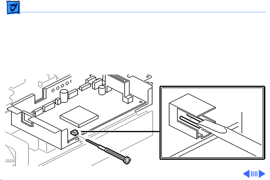
The LaserWriter Select service test page consists of a line matrix.
The LaserWriter Select printers produce a service test page when
you jumper the two pins at connector P32 on the DC controller
board. The test page confirms print engine operation.
DC Controller
Board
Screwdriver
or Paper Clip
P32
Page 27

Troubleshooting Service Test Page - 4
If the I/O controller mount is installed, you can access P32 by
inserting the straightened end of a paper clip through the small
access hole in the rear face of the I/O controller mount.
Caution:
is in an open test-ready state, you must manually actuate the
delivery sensor, otherwise a paper jam will occur. See "TestReady Configuration" in this chapter.
If you want to run a service test page while the printer
Page 28
Troubleshooting Test-Ready Configuration - 5
Test-Ready Configuration
Paper delivery sensor PS201 is connected to the I/O controller
mount. When you remove the mount to troubleshoot inside the
printer or to run a service test page, you must reconfigure the
sensing system to simulate an operational printer.
Page 29

Troubleshooting Test-Ready Configuration - 6
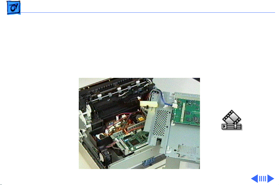
To reconfigure the sensing system, remove the I/O controller
mount and set it at an angle on top of the power supply. Position
the mount so that connector P32 on the DC controller board is
accessible.
Insert a folded piece of paper into the U of sensor PS201, and
make sure that the two cables are securely attached to the I/O
board. If you need to communicate with a Macintosh, you can do so
by reconnecting the serial connector.
Caution:
If the printer is in a test-ready configuration, you must manually
actuate this sensor as paper hits the delivery sensor actuator
within the fuser assembly.
Jumpering connector P32 initiates a service test page.
Page 30

Troubleshooting 310/360 Power-On Self Test - 7
310/360 Power-On Self Test
The LaserWriter Select 310 and 360 go through a self diagnostic
each time that you switch the printer on. This diagnostic is called
the Power-On Self Test (POST). POST does not occur on the
LaserWriter Select 300 printer.
Note:
This test is not the same as the engine diagnostic (see next
topic). Unlike the engine diagnostic test, POST does not require
the placement of any loopback cable.
Observing how the LEDs extinguish from that point can help
isolate certain failure areas.
• The Ready LED extinguishes when no errors are found on the
I/O controller board.
• The Paper-Out LED then extinguishes when no errors are found
on the RAM card.
Page 31

Troubleshooting 310/360 Power-On Self Test - 8
• Finally the Jam LED extinguishes when no errors are found in
the engine.
In a functional printer, control will be passed on to the PostScript
interpreter at the end of this sequence.
Page 32

Troubleshooting 360 Printer Diagnostic - 9
360 Printer Diagnostic
Note:
Only the LaserWriter Select 360 offers diagnostic LEDs.
Switch off the LaserWriter Select 360 printer, and remove the
jumper from JMP1 on the I/O controller if a jumper is present.
Set the mode switch on the printer's back panel to 9.
The reporting sequence (which repeats continuously) is as
follows:
• All LEDs are on for 1 second.
• All LEDs are off for 1 second.
• The LED(s) that indicates the error is on for 1 second.
• All LEDs are off for 1 second.
Error configurations are shown on the next page.
Page 33
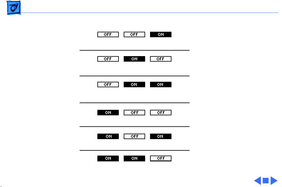
Troubleshooting 360 Printer Diagnostic - 10
I/O Controller Error
* A SIMM error can result
from insufficient memory.
SIMM Error*
Engine Controller Error
Fuser Error
Laser Error
Engine Error
You must have a minimum of
7 MB of RAM installed.
Page 34

Troubleshooting Circuit Board Diagrams - 11
Circuit Board Diagrams
Illustrations for the printed circuit boards below are located on
the following pages.
• LaserWriter Select 300 I/O Controller Board
• LaserWriter Select 310 I/O Controller Board
• LaserWriter Select 360 I/O Controller Board
• LaserWriter Select 300/310 DC Controller Board
• LaserWriter Select 360 DC Controller Board
• Cassette Feeder Board Diagram
• LaserWriter Select 300/310 High-Voltage Power Supply
• LaserWriter Select 360 High-Voltage Power Supply
• LaserWriter Select 360 Fax Card
Page 35

Troubleshooting Circuit Board Diagrams - 12
Select 300 I/O Controller Board
DRAM
P50 P51
SIMMs
Page 36

Troubleshooting Circuit Board Diagrams - 13
Select 310 I/O Controller Board
ROMs (1 or 2)
SIMMs
J3 JP2
DRAM
Page 37

Troubleshooting Circuit Board Diagrams - 14
Select 360 I/O Controller Board
P56
SIMMs
J3 JP2
J57
Page 38

Troubleshooting Circuit Board Diagrams - 15
Select 300/310 DC Controller Board
P14 P15 P16P17P18 P19
P11
P12
P31
P13
P32
Page 39

Troubleshooting Circuit Board Diagrams - 16
Select 360 DC Controller Board
P14 P15 P16P17P18 P19P20
P11
P12
P13
P32
P21
P31
Page 40

Troubleshooting Circuit Board Diagrams - 17
Cassette Feeder Board Diagram
P115
SW1
SW2
SW3
SW4
P116
P202
P201
Page 41

Troubleshooting Circuit Board Diagrams - 18
Select 300/310 High Voltage Power Supply
DB
RTN1
RTN2
P111
TR
CR
Page 42

Troubleshooting Circuit Board Diagrams - 19
Select 360 High Voltage Power Supply
CRTR
DB
RTN1 RTN2 P11
Page 43

Troubleshooting Circuit Board Diagrams - 20
Select 360 Fax Card
RJ-11
Battery
Volume Control
Speaker
J1
Page 44

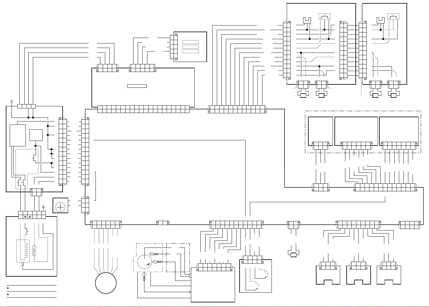
Troubleshooting Wiring Diagram - 21
Wiring Diagram
The LaserWriter Select wiring diagram can be found on the next
page. The detail in this document is too small to read easily at
100% view. You should either zoom into the diagram using the
zoom tool above, or print the diagram on a laser printer with a
resolution of 300 dpi (600 dpi preferred).
Page 45
FG
12
HEATER
CNT
INTERLOCK
P101
62314 5
J101
SW
3
24V
Supply
12
PS601
PAPER-OUT
1
2
3
4
5
6
7
8
9
10
11
12
FEED
CASSETTE FEEDER
P17
12
SENSOR
BEAM
DETECT
P113
5V
P19
J115 P115
LED STATUS PANEL
5VA
5VA
5VA
GND
GND
POWER
SUPPLY
P13
4
P11
14
4
1
5
2
3
6
7
8
9
10
11
12
13
FAN
/HEAT
GND
VS
GND
5VB
5VA
GND
RTN
RTN
24V
24V
24V
STS
(GND)
24V
RTN
J31
P31
1
2
3
4
5
6
7
P11
8
9
10
11
12
13
14
3
2
P18
1
J51
JP2
GND
GND
GND
/CMD
/CP RDY
/STARTNC/SBSY
B9B8B7B6B5B4B3B2B1
B10
P14
123456
READY/IN-USE
PAPER-OUT
JAM
123451234
J3
J57
/RDY
/BDNC/PRFD
/CCLK
A9A8A7A6A5A4A3A2A1
A10
DC CONTROLLER BOARD
P32
I/O BOARD
/VDONC/CBSY
/STA
12
5
4
3
2
1
/TOP
GREEN
RED
RED
/PPRDY
GND
1 2 3 4 5 6 7 8 9 10 11 12
1234567891011
P13
P15
NO PAPER 1
5V
NO PAPER 2
GND
SIZE 1
SIZE 2
24V
/TURN 1
/TURN 2
24V
/FEED 1
/FEED 2
SOLENOID
P116
SOLENOID
123
/SOS
GND
SIZING
SWITCHES
1
2
3
4
5
6
7
8
9
10
11
12
P201P202
PICKUP
LASER/OPTIC ASSEMBLY
SCANNER
MOTOR UNIT
P114
456
RTN
24V
/MOT ON
P16
1
2
3
4
5
6
Optional feeder
7
8
9
10
11
12
12 121212
OPTIONAL FEEDER
123
SPI2
SPI1
GND
10111213123
123456789
components
identical to
main feeder
LASER DRIVER
P112
1234567
VL1
VL2
5VB
GND
P12
12
MO
P21
5VA
123456789
34
/P DATA
Heater
Bulb
FUSER ASSEMBLY
100-120V
Pin 2
Heater NC
NC
Pin 3
STS
220-240V
Heater
/B
MOTOR
/A
MAIN
A
B
A-COM (24V)
B-COM (24V)
TONER
CARTRIDGE
Paper Charge Deflector
HIGH-VOLTAGE
CONTACT ASSEMBLY
RTN
DB
CRU
Paper Delivery Guide
Transfer Roller
Rtn
DB
CR
RTN
HIGH-VOLTAGE
TR
POWER SUPPLY
RTN
/DB
/TR +/-
P111
/TR
/CR-AC
/CR-DC
5VB
24V
TONER CARTRIDGE
SENSOR BOARD
S100
5V
EP Check
S101
1234
GND
P118
24V
/FEED
MANUAL FEED
PICKUP
SOLENOID
GND
/NO PAPER
PULLUP 5V
P121
PS701
MANUAL FEED
SENSOR
GND
/PREREG
PULLUP 5V
123
P120
PS602
REGISTRATION
SENSOR
GND
/EXIT
PULLUP 5V
123123
P119
PS201
PAPER DELIVERY
SENSOR
Page 46

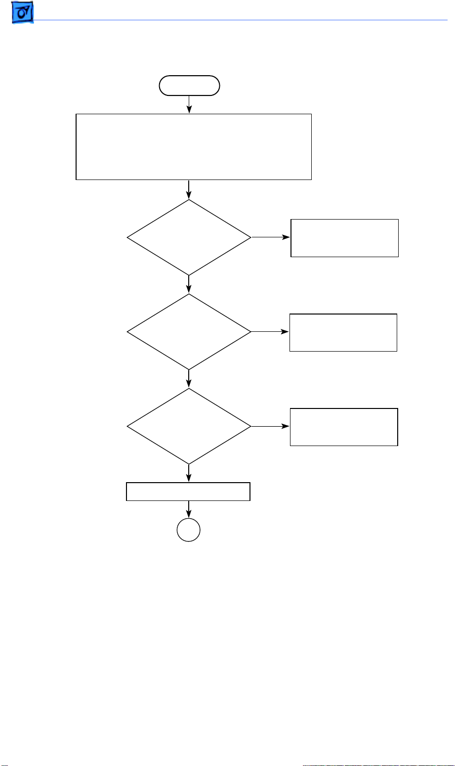
LaserWriter Select 300 Flowchart 1
START
1. Connect the printer to a Macintosh computer that is
using the LaserWriter Select 300 driver.
2. Open the printer and remove any paper jams.
3. Install the toner cartridge and fill the cassette tray.
4. Switch on the printer and the Macintosh computer
and wait 2 minutes.
5. Issue a Print Window or Print Directory command.
Flowcharts and TablesTroubleshooting
Does the
printer print
from a
Macintosh?
Yes
Is the
print quality
OK?
Yes
The printer is fully functional.
No
No
Go to LaserWriter
Select 300 Flowchart 2.
Go to "Print Quality
Problems."
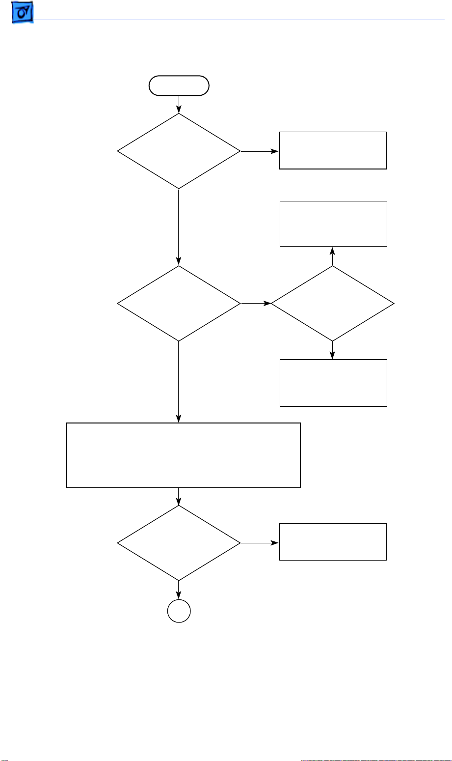
Page 47
LaserWriter Select 300 Flowchart 2
START
1. Switch off the printer and disconnect it from the
Macintosh computer.
2. Remove the top cover, rear cover, and side covers.
3. Remove the I/O shield and I/O board.
4. Plug in and switch on the printer.
Flowcharts and TablesTroubleshooting
Does
the fan
come on?
Yes
Does the
fuser bulb glow every
few seconds during
startup?
Yes
Does the
main motor
rotate sometime
after startup?
Yes
Initiate a service test page.
No
No
No
Go to Table 2,
No Power to Fan.
Go to Table 3,
Fuser Assembly
Failure.
Go to Table 1,
Main Motor
Failure.
A
Page 48

Flowcharts and TablesTroubleshooting
LaserWriter Select 300 Flowchart 2 (Continued)
A
Did the
printer deliver
a service test
page?
Yes
Is the
print quality
OK?
No
No
Go to Table 27, 28, 29,
or 30, depending
on the specific paper
transport problem.
Yes
Did the
paper jam
inside the
printer?
No
Go to Table 4
or 5, depending
on the specific laser/
scanner malfunction.
Go to "Print Quality
Problems."
Yes
1. Make sure cable connections are correct, secure,
and undamaged.
2. Confirm that the proper print driver is installed.
3. If the printer is connected to the Macintosh printer
port, open the Chooser and make AppleTalk
inactive.
4. If the problem persists, replace the I/O board.
Page 49

LaserWriter Select 310 Flowchart 1
START
1. Connect the printer to a Macintosh computer that
is using the LaserWriter Select 310 driver.
2. Open the printer and remove any paper jams.
3. Install the toner cartridge and fill the cassette tray.
4. Switch on the printer and the Macintosh computer
and wait 2 minutes.
Flowcharts and TablesTroubleshooting
Does the
Ready LED glow
steadily after
warmup?
Yes
Open the File menu and choose Print
Window or Print Directory.
Does the
printer print
from a
Macintosh?
Yes
Is the
print quality
OK?
Yes
1. Place paper on the manual feed tray.
2. Open the File menu and choose Print Window
or Print Directory.
3. Select Manual Feed as the paper source in the
Print dialog box.
No
No
No
Go to LaserWriter
Select 310 Flowchart 2.
Go to Table 7
or 8, depending
on the specific I/O
board error.
Go to "Print Quality
Problems."
Does the
printer deliver
a manually fed
page?
Yes
The printer is fully functional.
No
Go to Table 30,
No Paper Pickup From
Manual Feed or
Multipurpose Tray.
Page 50
Flowcharts and TablesTroubleshooting
LaserWriter Select 310 Flowchart 2
START
Is the
Paper-Out
LED on?
No
Is the
Paper-Jam
LED on?
No
Yes
Yes
Go to Table 13,
Paper-Out LED Lights
When There Is Paper.
Go to Table 27, 28, 29,
or 30, depending
on the specific paper
transport problem.
Yes
Is the
paper jammed
inside the
printer?
No
Go to Table 14,
Paper-Jam LED Lights
But No Jam
Has Occurred.
1. Switch off the printer and disconnect it from the
Macintosh computer.
2. Remove the top cover, rear cover, and side covers.
3. Remove the I/O shield and the I/O board.
4. Plug in and switch on the printer.
Does
the fan
come on?
Yes
A
No
Go to Table 2,
No Power to Fan.
Page 51

Flowcharts and TablesTroubleshooting
LaserWriter Select 310 Flowchart 2 (Continued)
A
Does the
fuser bulb glow every
few seconds during
startup?
Yes
Does the
main motor
rotate sometime
after startup?
Yes
Initiate a service test page.
Did the
printer deliver
a service
test page?
No
No
No
Go to Table 3,
Fuser Assembly
Failure.
Go to Table 1,
Main Motor
Failure.
Go to Table 27, 28, 29,
or 30, depending
on the specific paper
transport problem.
Yes
Did the
paper jam
inside the
printer?
Yes
Is the
print quality
OK?
Yes
B
No
No
Go to Table 4 or 5,
depending on the
specific laser or
scanner problem.
Go to "Print Quality
Problems."
Page 52

Flowcharts and TablesTroubleshooting
LaserWriter Select 310 Flowchart 2 (Continued)
B
1. Switch off the printer.
2. Replace the I/O board, I/O shield, and covers.
3. Reconnect the printer to a Macintosh computer.
4. Switch on the printer and the computer.
5. Open the File menu and choose Print Window
or Print Directory.
printout of the active
Is a
window produced?
Yes
1. Place paper on the manual feed tray.
2. Open the File menu and choose Print Window
or Print Directory.
3. Select Manual Feed as the paper source in the
Print dialog box.
Is a
printout of the active
window produced?
Yes
The printer is fully functional.
No
No
Go to Table 7 or 8,
depending on the
specific I/O
board problem.
Go to Table 30, No
Paper Pickup From
Manual Feed or
Multipurpose Tray.
Page 53

Flowcharts and TablesTroubleshooting
LaserWriter Select 360 Flowchart 1
START
Run the LaserWriter Select 360 printer diagnostic (see "Printer Diagnostics"
section). Replace modules as indicated in the "Printer Diagnostics" section.
If no specific error is indicated during the diagnostic, switch off the printer,
jumper the pins at JMP1 on the I/O controller, and return the mode switch
to its original setting.
Does the
Ready/In Use LED
glow steadily after
warmup?
Yes
Open the File menu and choose Print Window or Print Directory.
Does the
printer print
from a
Macintosh?
Yes
Is the
print quality
OK?
Yes
1. Place paper on the manual feed tray.
2. Open the File menu and choose Print Window or Print Directory.
3. Select Manual Feed as the paper source in the Print dialog box.
No
No
No
Go to Flowchart 2.
Go to Table 7 or 8,
depending on the specific
I/O board error.
Go to "Print Quality
Problems."
Does the
printer deliver
a manually fed
page?
Yes
The printer is fully functional.
No
Go to Table 30,
No Paper Pickup From
Manual Feed or
Multipurpose Tray.
Page 54

Flowcharts and TablesTroubleshooting
LaserWriter Select 360 Flowchart 2
START
Is the
Paper-Out
LED on?
No
Is the
Paper-Jam
LED on?
No
Yes
Yes
Go to Table 23,
Paper-Out LED Lights
When There Is Paper.
Go to Table 27, 28, 29,
or 30, depending
on the specific paper
transport problem.
Yes
Is the
paper jammed
inside the
printer?
No
Go to Table 24,
Paper-Jam LED Lights
But No Jam
Has Occurred.
1. Switch off the printer and disconnect it from the
Macintosh computer.
2. Remove the top cover, rear cover, and side covers.
3. Remove the I/O shield and the I/O board.
4. Close the front access door.
5. Plug in and switch on the printer.
Does
the fan
come on?
Yes
A
No
Go to Table 2,
No Power to Fan.
Page 55

Flowcharts and TablesTroubleshooting
LaserWriter Select 360 Flowchart 2 (Continued)
A
Does the
fuser bulb glow every
few seconds during
startup?
Yes
Does the
main motor
rotate sometime
after startup?
Yes
Initiate a service test page.
Did the
printer deliver
a service
test page?
No
No
No
Go to Table 3,
Fuser Assembly
Failure.
Go to Table 1,
Main Motor
Failure.
Go to Table 27, 28, 29,
or 30, depending
on the specific paper
transport problem.
Yes
Did the
paper jam
inside the
printer?
Yes
Is the
print quality
OK?
Yes
B
No
No
Go to Table 4 or 5,
depending on the
specific laser or
scanner problem.
Go to "Print
Quality Problems."
Page 56

Flowcharts and TablesTroubleshooting
LaserWriter Select 360 Flowchart 2 (Continued)
B
1. Switch off the printer.
2. Reinstall the I/O board, I/O shield, and covers.
3. Reconnect the printer to a Macintosh computer.
4. Switch on the printer and the computer.
5. Open the File menu and choose Print Window
or Print Directory.
printout of the active
Is a
window produced?
Yes
1. Place paper on the manual feed tray.
2. Open the File menu and choose Print Window
or Print Directory.
3. Select Manual Feed as the paper source in the
Print dialog box.
Is a
printout of the active
window produced?
Yes
The printer is fully functional.
No
No
Go to Table 6, 7, or 8,
depending on the
specific I/O
board problem.
Go to Table 30, No
Paper Pickup From
Manual Feed or
Multipurpose Tray.
Page 57

Flowcharts and TablesTroubleshooting
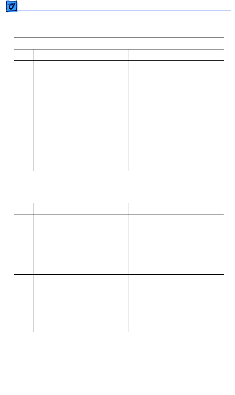
Important
As you proceed through the steps in a table, remember to retry the printer each
time you change its physical state–for example, when you replace a module. If
the problem remains, reinstall the original module before proceeding to the
next step in the table. Refer as necessary to the wiring diagram that follows the
tables.
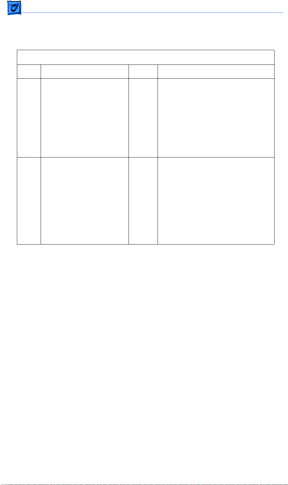
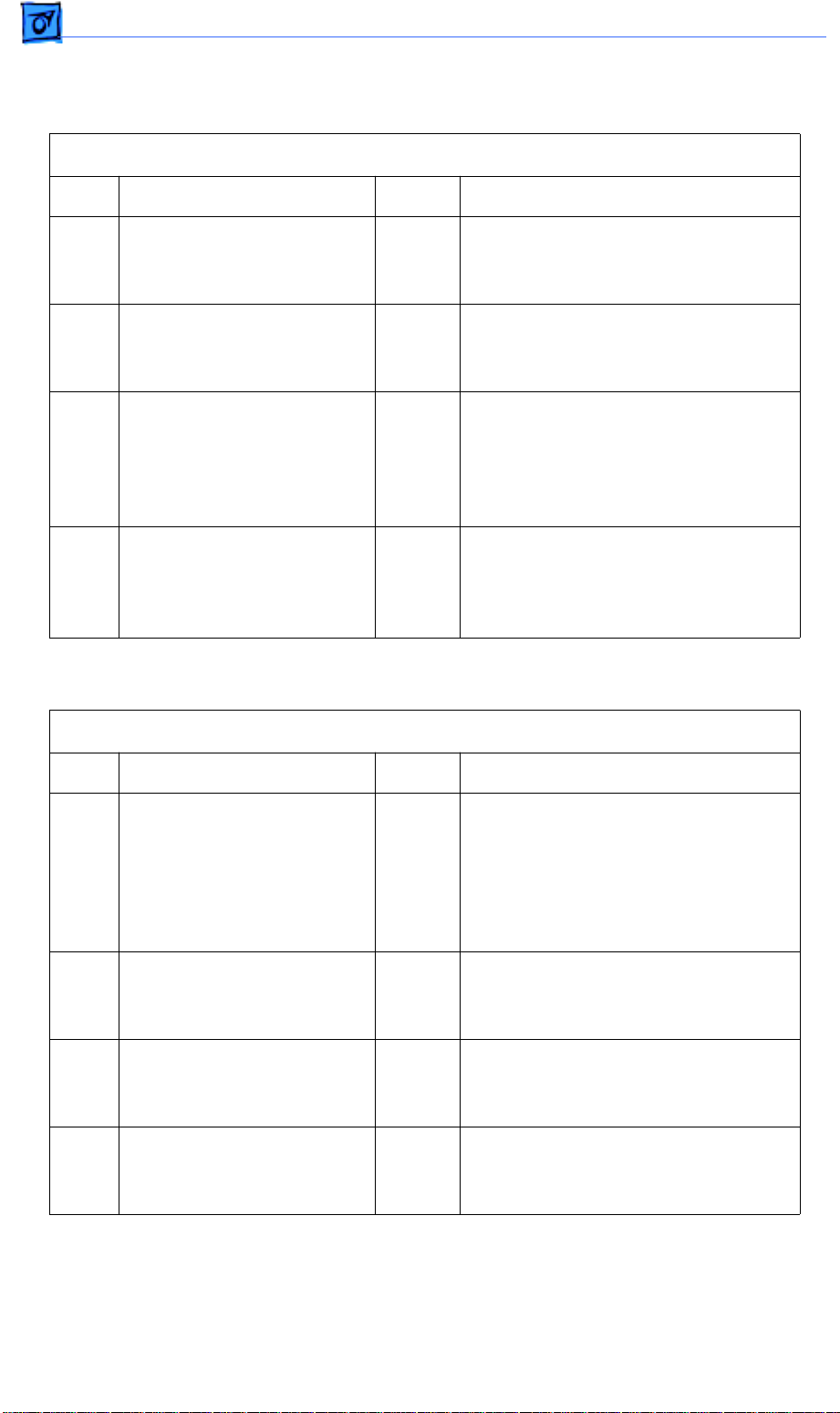
Table 1. Main Motor Failure
Step Check Result Action
1 Is connector P14 on the DC
controller board making
good contact?
2 Are there any obstructions
in the drive assembly gear
train or paper path?
3 Inspect the drive assembly
gear train and replace any
damaged gears. (Check the
gears on the drive
assembly, the paper feed
roller, and the cassette
feeder assembly.) Does the
problem persist?
No Reconnect P14 to the DC controller
board.
Yes Remove the obstructions.
No Problem solved.
4 Switch off the printer and
connect a multimeter
between each of the
following pairs of pins:
• P14-1 (A-COM 24V)
and P11-2 (GND)
• P14-2 (B-COM 24V)
and P11-2 (GND)
Does the voltage measure
approximately +24 VDC
when you switch on the
printer?
No Go to Table 11, Power Supply Failure
(+24 VDC).
3
Page 58
Flowcharts and TablesTroubleshooting
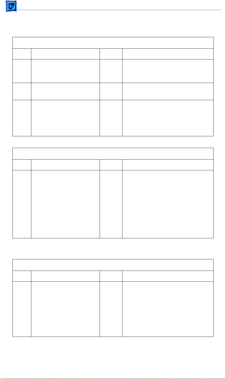
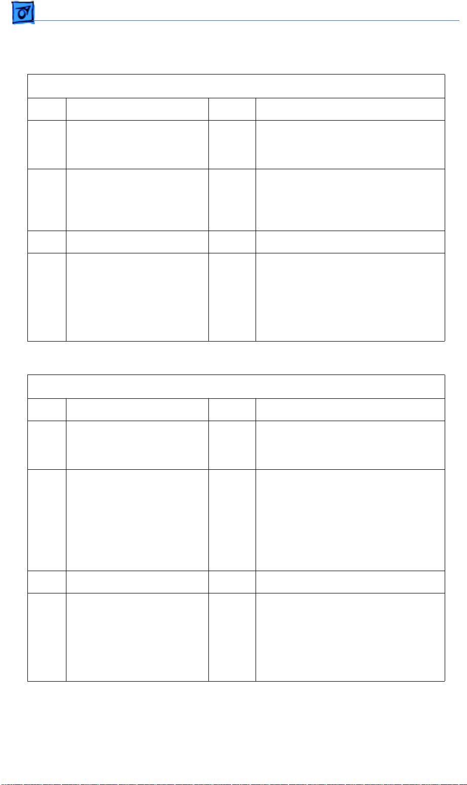
Main Motor Failure (Continued)
Step Check Result Action
5 Switch off the printer and
connect a multimeter
between each of the
following pairs of pins:
• P14-1 (A-COM 24V) and
P14-3 (A)
• P14-1 (A-COM 24V) and
P14-5 (/A)
• P14-2 (B-COM 24V) and
P14-4 (B)
• P14-2 (B-COM 24V) and
P14-6 (/B)
Is the resistance
approximately 5 ohms?
No
Yes
Replace the main motor.
Replace the DC controller board. If
the problem persists, replace the
main motor.
Table 2. No Power to Fan
Step Check Result Action
1 Is a toner cartridge installed
in the printer?
2 Is the AC outlet providing
the correct voltage?
3 Is connector P119 making
good contact with the paper
delivery sensor?
4 Inspect the paper delivery
sensor. Does the lever on
the fuser assembly cover
the paper delivery sensor
when no paper is present
and uncover the sensor
when paper passes through
the fuser assembly?
No Install a toner cartridge.
No Try another AC outlet.
No Reconnect connector P119 to the
paper delivery sensor.
No Install the paper delivery sensor so
that it makes contact with the delivery
sensor lever. If the problem persists,
replace the delivery sensor lever.
Page 59
Flowcharts and TablesTroubleshooting
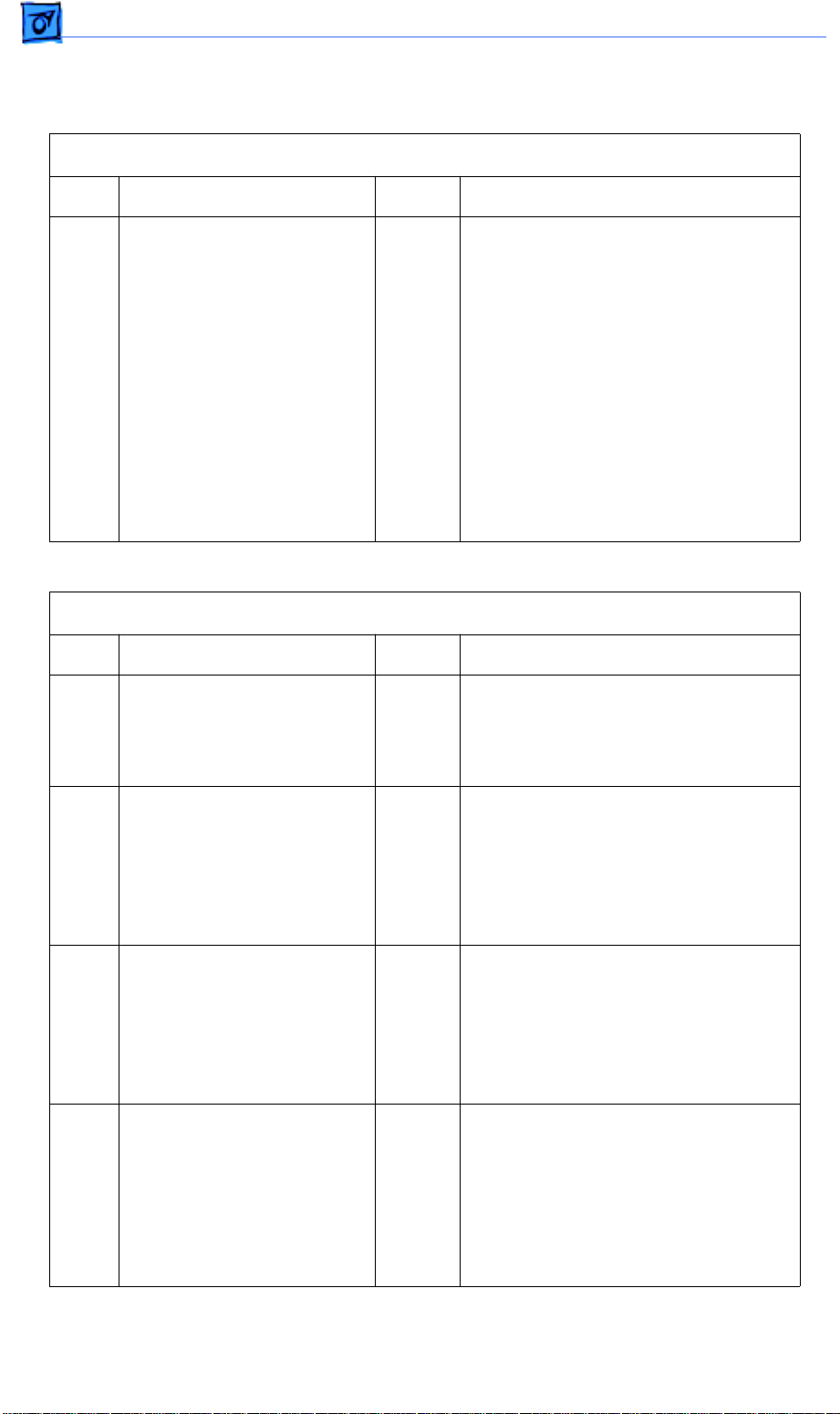
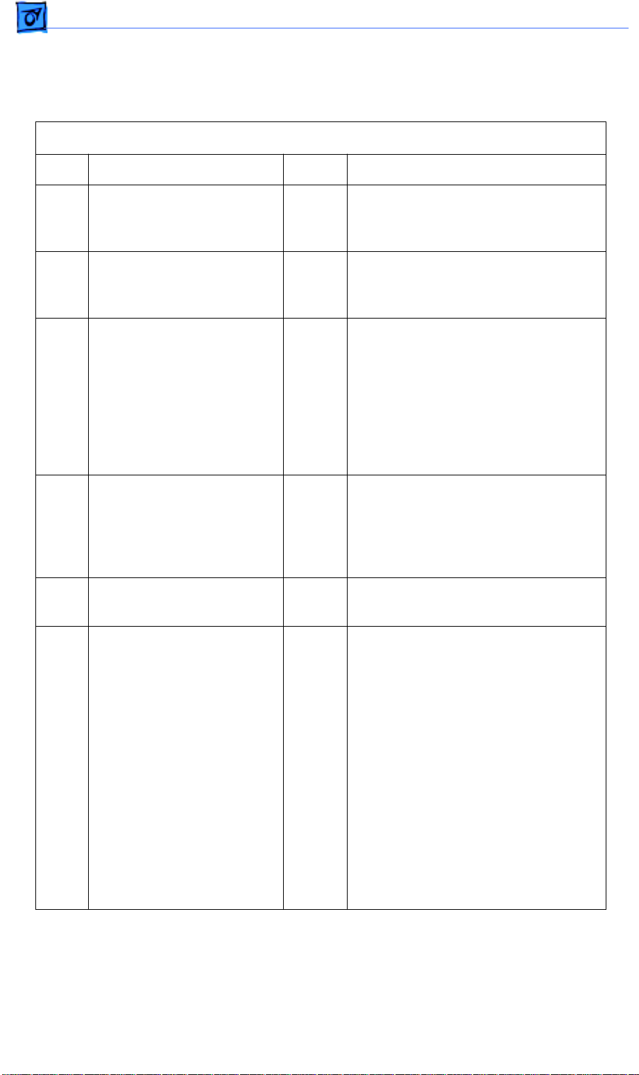
No Power to Fan (Continued)
Step Check Result Action
5 Connect a multimeter
between each of the
following sets of pins and
check for the following
voltages:
P11-10 (+24 V, brown wire)
and P11-2 (GND, black
wire) +24 VDC
P11-11 (+24 V, brown wire)
and P11-2 (GND, black
wire) +24 VDC
P11-12 (+24 V, orange wire)
and P11-2 (GND, black
wire) +24 VDC
P11-5 (+5 VB, yellow wire)
and P11-2 (GND, black
wire) +5 VDC
P11-6 (+5 VA, blue wire)
and P11-2 (GND, black
wire) +5 VDC
Are the voltages present
when you switch the printer
back on?
No Replace the power supply.
3
6 Switch off the printer,
connect a multimeter
between connectors P18-3
(+24V) and P18-2 (RTN) on
the DC controller, and
switch the printer back on.
Is the voltage approximately
+24 VDC?
Yes Replace the fan.
Page 60
Ω
Flowcharts and TablesTroubleshooting
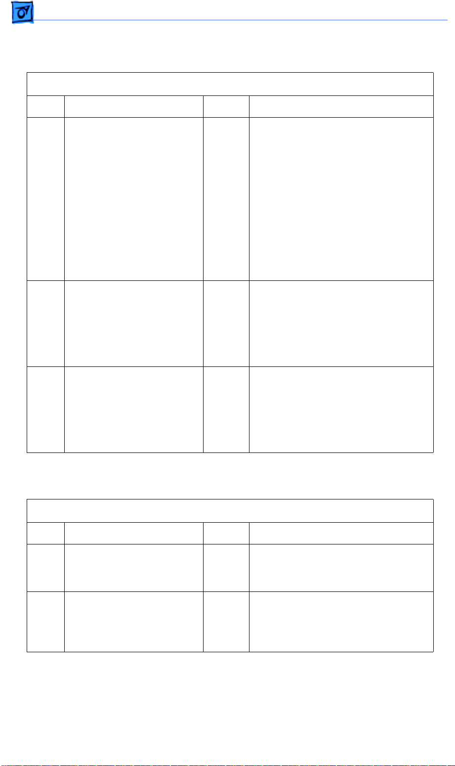
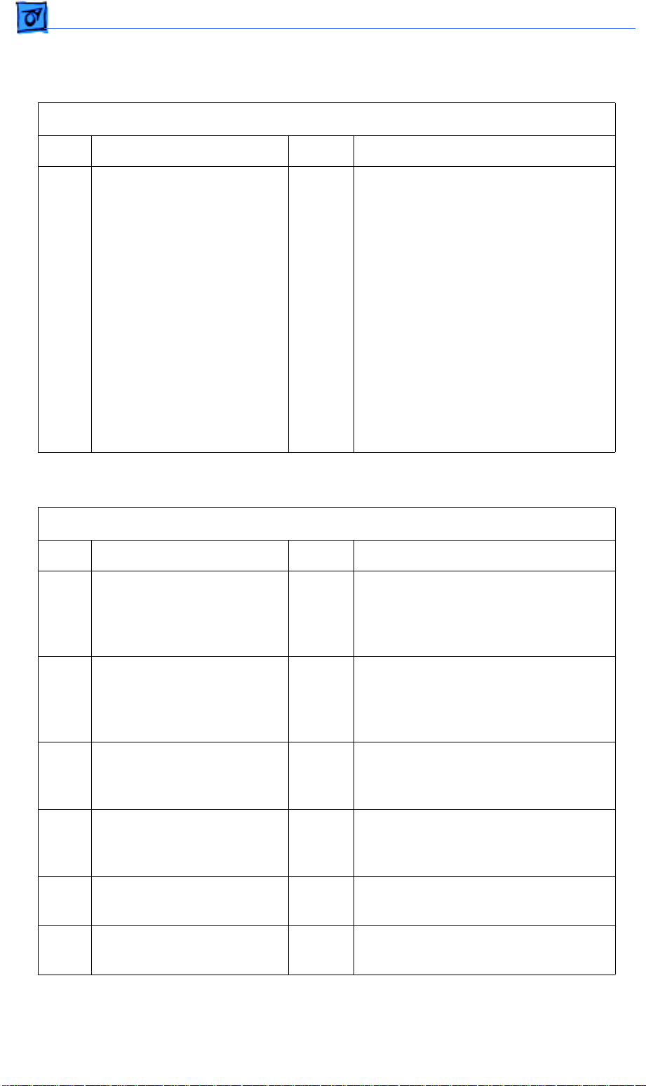
No Power to Fan (Continued)
Step Check Result Action
7 Switch off the printer and
disconnect connector P119
from the paper delivery
sensor. Connect the
multimeter between P119-2
(GND) and P119-3
(+5 VDC) and switch on the
printer. Does the voltage
measure approximately +5
VDC when you switch on
the printer?
No
Yes
Check the cable connections between
P119 and P16 on the DC controller
board. If the connections are secure,
replace the DC controller board.
Replace the paper delivery sensor.
Table 3. Fuser Assembly Failure
Step Check Result Action
1 Is a toner cartridge installed
in the printer?
2 Switch off the printer,
connect a multimeter
between pins J101-2 and
J101-6 on the fuser
assembly , and s witch on the
printer. Does the voltage
measure between +90 and
+132 VAC when you switch
on the printer?
No Install a toner cartridge.
No Replace the power supply.
3 Switch off the printer,
disconnect connector P11
from the DC controller
board. Measure the
resistance between
connector pins P11-13
(STS) and P11-14 (GND). Is
the resistance between
200 k
temperature?
and 350 k Ω at room
No Replace the power supply.
Page 61
Flowcharts and TablesTroubleshooting
Fuser Assembly Failure (Continued)
Step Check Result Action
4 Measure the resistance
between pins J101-2 and
J101-6 on the fuser
assembly. Is the resistance
less than 10 Ω ?
5 Connect a multimeter
between pins P11-1 (HEAT,
red wire) and P11-2 (GND,
black wire). Does the
voltage measure about
+4.2 VDC when you switch
on the printer?
6 Connect a multimeter
between connector pins
P11-1 (HEAT, red wire) and
P11-2 (GND, black wire) on
the DC controller board.
When you open and close
the front access door, does
the voltage measure about
+3.7 VDC with the door
open and briefly drop to
0 VDC about five seconds
after you close the door?
7 Switch off the printer and
disconnect P111 from the
high-voltage power supply.
Connect a multimeter
between connector pins
P11-5 (5 VB, yellow wire)
and P11-2 (GND, black
wire) on the DC controller
board. Does the voltage
measure about +5 VDC
when you switch on the
printer?
No Replace the fuser heater bulb and the
thermoprotector.
No Replace the power supply.
No Go to Table 9, Temperature Sensor
Assembly Failure.
3
No Replace the power supply.
Page 62

Ω
Ω
Flowcharts and TablesTroubleshooting
Fuser Assembly Failure (Continued)
Step Check Result Action
8 Switch off the printer and
disconnect connector P12
from the DC controller
board. Does the fuser
heater bulb light when you
switch on the printer?
9 Switch off the printer and
disconnect connector P15
from the DC controller
board. Does the fuser
heater bulb light when you
switch on the printer?
10 Connect the multimeter
between pins P15-8 (5 VB,
yellow wire) and P15-9 (5 V,
orange wire) on the DC
controller board. When you
remove and insert the toner
cartridge does the
resistance change from 0
(cartridge inserted) to
infinity Ω (cartridge
removed)?
No Replace the laser/optic assembly.
Yes Replace the DC controller board.
No Replace the toner cartridge sensor
assembly.
11 Connect the multimeter
between pins P15-10 (EP
CHECK, red wire) and
P15-11 (GND, brown wire)
on the DC controller board.
When you remove and
insert the toner cartridge,
does the resistance
change from 0
inserted) to infinity Ω
(cartridge removed)?
(cartridge
No Replace the toner cartridge sensor
assembly.
Page 63
Ω
Flowcharts and TablesTroubleshooting
Table 4. Laser Scanner Failure
Step Check Result Action
1 Are connectors P12 and
P19 on the DC controller
board properly seated?
2 Switch on the printer, wait
until the main motor stops
rotating, and connect a
multimeter between
connector P12-11 (/MOT
ON) on the DC controller
board and chassis ground.
Can you hear the scanner
motor start to spin?
3 Switch off the printer,
connect a multimeter
between connectors P11-4
(GND, black wire) and
P11-5 (5 VB, yellow wire)
on the DC controller board,
and switch on the printer. Is
the voltage approximately
+5VDC?
No Reconnect connectors P12 and P19
to the DC controller board.
No Go to Table 5, Scanner Assembly
Failure.
No Replace the power supply.
4 Switch off the printer and
connect a multimeter
between connectors P11-5
(5 VB, yellow wire) and
P12-7 (5 VB, black wire) on
the DC controller board. Is
the resistance less than
?
5
5 Switch off the printer and
connect a multimeter
between connectors P12-7
(5 VB) and P12-6 (GND) on
the DC controller board.
Does the voltage measure
+5 VDC when you switch
on the printer?
No Go to Table 9, Toner Cartridge Sensor
Failure.
Yes
No
Replace the laser/optic assembly.
Replace the DC controller board.
3
Page 64
Flowcharts and TablesTroubleshooting
Table 5. Scanner Assembly Failure
Step Check Result Action
1 Switch off the printer and
connect a multimeter
between connectors
P12-13 (24 V) and P12-12
(RTN) on the DC controller
board. Does the voltage
measure about +24 VDC
when you switch on the
printer?
2 Connect a multimeter
between connectors P12-11
(/MOT ON) and P12-10
(GND) on the DC controller
board and initiate a service
test page. Does the voltage
drop to less than +1 VDC
during printing and rise to
about +4 VDC when the
printing stops?
No Go to Table 11, Power Supply Failure
(+24 VDC).
Yes
No
Replace the scanner assembly. If the
problem persists, replace the laser
and scanner motor cable.
Replace the DC controller board.
Page 65

Flowcharts and TablesTroubleshooting
Table 6. Select 360 I/O Board Error
Step Check Result Action
1 Are the serial and/or
parallel cables secure?
2 If you are using a
Macintosh, is the
LaserWriter Select 360
driver installed in the
System Folder?
3 If you are using an IBM PC
or compatible computer,
check that the correct
printer driver is installed.
Has it been installed?
No Tighten the cable connections.
No Use the installation disk to install the
appropriate driver in the System
folder.
No Install the correct Windows printer
driver. Refer to the user’s guide for
more information.
3
Page 66

Flowcharts and TablesTroubleshooting
Select 360 I/O Board Error (Continued)
Step Check Result Action
4 If you are using a
Macintosh, are the
LaserWriter 8.0 driver (icon)
and correct serial port
selected?
5 If you are using an IBM PC
or compatible computer, is
the Windows program
open and active?
6 If you are using a
Macintosh, is background
printing disabled?
No Use the Chooser to select the
LaserWriter 8.0 driver.
No Make sure the window is open and
the document window is active.
Choose Print from the File menu,
select the options you want, and click
Print.
No
Yes
Disable background printing (so that
error messages display on the
screen). Switch the printer off and on
again.
Install a different LaserWriter Select
360 I/O board.
Table 7. Select 310 or 360 I/O Board Error – Serial Connection
Step Check Result Action
1 Is the serial cable
connection secure?
2 Is the serial cable good? No Replace cable.
3 Is the LaserWriter Select
360 driver installed in the
System Folder?
4 Are the correct LaserWriter
Select driver and serial port
selected?
5 Is the printer connected to
the printer port on the
Macintosh?
6 Is background printing
disabled?
No Tighten cable connections.
No Use the Installer to install the
LaserWriter Select 360 driver in the
System Folder.
No Use the Chooser to select the
LaserWriter Select 310 or 360 driver
and the port (printer or modem) to
which the printer is connected.
Yes Make sure AppleTalk is inactive.
No Disable background printing. If the
problem persists, install a different
LaserWriter Select 360 I/O board.
Page 67
Flowcharts and TablesTroubleshooting
Table 8. Select 310 or 360 I/O Board Error – Parallel Connection
Step Check Result Action
1 Are the parallel cable
connections correct and
secure?
2 Are the parallel cables and
connectors good?
3 Are the software and
hardware properly
configured to communicate
with the parallel port on the
printer?
No Tighten cable connections.
No Replace the defective cables and
connectors.
No Refer to the printer’s owner’s guide
and the computer documentation for
proper configuration. Switch the
printer off and on again. If the problem
persists, install a different I/O board.
Table 9. Temperature Sensor Assembly Failure
Step Check Result Action
1 After allowing the fuser
assembly to cool to room
temperature, remove the
fuser assembly from the
printer. Measure the
resistance between J101-1
and J101-4 on the fuser
assembly. Is the resistance
between 200 k Ω and
350 k Ω ?
No Replace the sensor assembly.
3
Table 10. Toner Cartridge Sensor Failure
Step Check Result Action
1 Switch off the printer.
Connect a multimeter
between P15-8 (5 VB) and
P11-2 (GND) on the DC
controller board. Does the
voltage measure +5 VDC
when you switch on the
printer?
No Go to Table 12, Power Supply Failure
(+5 VDC).
Page 68

Flowcharts and TablesTroubleshooting
Ω
Toner Cartridge Sensor Failure (Continued)
Step Check Result Action
2 Connect a multimeter
between pins P15-8 (5 VB,
yellow wire) and P15-9 (5 V,
orange wire) on the DC
controller board. When you
remove and insert the toner
cartridge, does the
resistance change from 0 Ω
(cartridge inserted) to
infinity Ω (cartridge
removed)?
3 Connect a multimeter
between pins P15-10 (EP
CHECK, red wire) and
P15-11 (GND, brown wire)
on the DC controller board.
When you remove and
insert the toner cartridge,
does the resistance
change from 0
inserted) to infinity Ω
(cartridge removed)?
(cartridge
No Replace the toner cartridge sensor
assembly.
No Replace the toner cartridge sensor
assembly.
4 Remove the toner cartridge
sensor cover and observe
the toner cartridge sensor
PCB and actuator.
Does the actuator turn on
switches S101 and S100
when you install a toner
cartridge and turn off the
switches when you remove
the toner cartridge?
5 Is there continuity between
connectors P15 on the DC
controller board and P118
on the toner cartridge
sensor board.
No Install a new toner cartridge. If
switches S101 and S100 still do not
turn on when you install the cartridge,
replace the toner cartridge sensor
assembly.
Yes
No
Replace the DC controller board.
Replace the high-voltage/toner
cartridge sensor cable.
Page 69

Flowcharts and TablesTroubleshooting
Table 11. Power Supply Failure (+24 VDC)
Step Check Result Action
1 Switch off the printer.
Connect a multimeter
between P11-12 (+24 VDC,
orange wire) and P11-2
(GND, black wire) on the
DC controller board. Switch
on the printer. Is the voltage
approximately +24 VDC?
2 Switch off the printer.
Connect a multimeter
between P11-10 (+24 VDC,
brown wire) and P11-2
(GND, black wire) on the
DC controller board. Switch
the printer back on. When
you open and close the
front access door, does the
voltage measure 0 VDC
with the door open and
+24 VDC with the door
closed?
No Replace the power supply.
Yes Replace the DC controller board.
3 Switch off the printer.
Connect a multimeter
between P11-11 (+24 VDC,
brown wire) and P11-2
(GND, black wire) on the
DC controller board. Switch
the printer back on. When
you open and close the
front access door, does the
voltage measure 0 VDC
with the door open and +24
VDC with the door closed?
Yes
No
Replace the DC controller board.
3
Replace the power supply.
Page 70
Flowcharts and TablesTroubleshooting
Table 12. Power Supply Failure (+5 VDC)
Step Check Result Action
1 Connect a multimeter
between the following pairs
of pins on the DC controller
board:
P11-5 (yellow wire) and
P11-2 (black wire)
P11-6 (blue wire) and
P11-2 (black wire)
Does the voltage measure
+5 VDC when you switch
on the printer?
No
Yes
Replace the power supply.
Replace the DC controller board.
Table 13. Paper-Out LED Lights When There Is Paper
Step Check Result Action
1 Is the paper cassette
installed and does it contain
paper?
No Remove the paper cassette tray and
fill it with paper. Reinstall the paper
cassette tray and make sure it is
seated properly.
2 Remove the paper
cassette tray and inspect
the paper sensing arm.
Does the paper sensing
arm appear to be
damaged?
3 While the paper cassette
tray is out, inspect the
paper cassette size
actuators. Do any of the
actuators appear to be bent
or damaged?
4 While the paper cassette
tray is out, switch on the
printer. Insert the paper
cassette tray. Does the
main motor rotate when you
insert the paper cassette
tray?
Yes Replace the paper sensing arm.
Yes Replace the cassette feeder board.
No Replace the cassette feeder board.
Page 71

Flowcharts and TablesTroubleshooting
Paper-Out LED Lights When There Is Paper (Continued)
Step Check Result Action
5 Prepare the printer for
troubleshooting as
described in the
“Troubleshooting
Preparation” section.
Disconnect P111 from the
high-voltage power supply.
Connect a multimeter
between connector pins
P13-1 (NOPAPER1) and
P13-4 (GND) on the DC
controller board. Remove
and insert the paper
cassette tray filled with
paper. Does the voltage
toggle from +5 VDC (tray
removed) to 0 VDC (tray
inserted)?
6 If an optional paper
cassette is installed,
connect a multimeter
between connector pins
p13-3 (NOPAPER2) and
P13-4 (GND) on the DC
controller board. Remove
and insert the paper
cassette tray filled with
paper. Does the voltage
toggle from +5 VDC (tray
removed) to 0 VDC (tray
inserted)?
No
Yes
No
Yes
Replace the cassette feeder board. If
the problem persists, replace the
cassette feeder tray cable.
Replace the DC controller board.
Replace the cassette feeder board. If
the problem persists, replace the
expansion feeder cable.
Replace the DC controller board.
3
Page 72

Flowcharts and TablesTroubleshooting
Table 14. Paper-Jam LED Lights But No Jam Has Occurred
Step Check Result Action
1 Is the paper cassette
installed and does it contain
paper?
2 Check the fuser/delivery
area or paper registration
area for paper fragments.
Are there any paper
fragments or other
obstructions?
3 Is the cable that runs to the
paper delivery sensor
securely connected?
4 Initiate a service test page
and observe the action of
the delivery lever on the
fuser assembly.
Does the delivery lever
swing freely when it passes
through the fuser
assembly?
No Remove the paper cassette tray and
fill it with paper. Reinstall the paper
cassette tray and make sure it is
seated properly.
Yes Remove the fragments or
obstructions.
No Reconnect the cable to the paper
delivery sensor.
No Replace the delivery sensor lever.
5 Open the front access door
and locate the paper
registration on the paper
charge deflector. Is the
paper sensing arm
damaged or broken.
Yes Replace the paper sensing arm.
Page 73

Flowcharts and TablesTroubleshooting
Paper-Jam LED Lights But No Jam Has Occurred (Continued)
Step Check Result Action
6 Prepare the printer for
troubleshooting as
described in
“Troubleshooting
Preparation.” Disconnect
connector P111 from the
high-voltage power supply
and connector P16 from the
DC controller board.
Connect a multimeter
between P16-4 (PULLUP 5
V) and P16-5 (GND) on the
DC controller board. Does
the voltage measure +5
VDC when you switch on
the power?
7 Switch off the printer and
reconnect connector P16
to the DC controller board.
Connect a multimeter
between connector P16-6
(PregReg) and P16-5
(GND) on the DC controller
board. Initiate a service test
page. Does the voltage
drop from +5 VDC to 0 VDC
when the paper passes the
paper registration sensor?
No Go to Step 9.
No Go to Step 9.
3
8 Switch off the printer.
Connect a multimeter
between connector P16-3
(EXIT) and P16-2 (GND).
Switch on the printer and
manually actuate the paper
delivery sensor by inserting
a sheet of paper between
the sensor arms.
Does the voltage drop from
+5 VDC to 0 VDC when you
remove the paper from the
sensor?
No Replace the paper delivery sensor. If
the problem persists, replace the
delivery sensor cable.
Page 74

Flowcharts and TablesTroubleshooting
Paper-Jam LED Lights But No Jam Has Occurred (Continued)
Step Check Result Action
9 Switch off the printer and
connect a multimeter
between the following pairs
of pins on the DC controller
board:
P11-5 (yellow wire) and
P11-2 (black wire)
P11-6 (blue wire) and
P11-2 (black wire)
Does the voltage measure
+5 VDC when you switch
on the printer?
The following graphic shows examples of image quality defects. Refer to the
appropriate troubleshooting table to correct the quality of the image.
No
Yes
Replace the power supply
Replace the DC controller board.
All-Blank Page
See Table 15
Black Vertical
Line(s)
See Table 19
Ghosting
See Table 23
All-Black Page
See Table 16
White Vertical
Line(s)
See Table 20
Bad Fusing
See Table 24
Light/Faded Image
See Table 17
Black Horizontal
Lines
See Table 21
Blank Spots
See Table 25
Dark Image
See Table 18
White Horizontal
Lines
See Table 22
Toner on Back
See Table 26
Page 75

Flowcharts and TablesTroubleshooting
Figure 31. Print Quality Problems
Table 15. All-Blank Page
Step Check Result Action
1 Remove the toner cartridge
from the printer. Is the toner
cartridge sealing tape
removed?
2 Replace the toner cartridge.
Does the print quality
improve?
3 Are the high-voltage
contacts making good
contact with the toner
cartridge?
4 Remove the toner cartridge
from the printer. Is any
foreign material blocking
the laser beam outlet on the
inside of the printer
chassis? Is any
foreign material adhering to
the laser beam access slot
on the toner cartridge?
No Remove the sealing tape.
Yes Problem solved.
No Clean the contacts or replace the
high-voltage contact assembly.
Yes Remove the foreign material.
5 Inspect the drive assembly
gear train. Are any gears
damaged?
6 Replace the transfer roller.
Does the print quality
improve?
7 Connect the multimeter
between connectors P15-7
and P15-1 on the DC
controller board. Does the
voltage measure +24 VDC
when you switch on the
printer?
Yes Replace the drive assembly.
Yes Problem solved.
No Go to Table 11, Power Supply Failure
(+24 VDC).
3
Page 76
Flowcharts and TablesTroubleshooting
All-Blank Page (Continued)
Step Check Result Action
8 For Steps 8 and 9, remove
the top covers, side covers,
rear cover, I/O board
mount, and the power
switch lever.
Remove the high-voltage
contact assembly and
check the continuity on all
the high-voltage contacts.
Do you find continuity on all
the high-voltage contacts?
9 Is there continuity between
connector RTN (red wire)
on the high-voltage power
supply and the red spade
connector on the paper
delivery guide?
10 Replace the DC controller
board. Does the print
quality improve?
No Replace the high-voltage contact
assembly.
No Replace the paper delivery guide.
Yes
No
Problem solved.
Replace the toner cartridge sensor
and high-voltage power supply cable.
If the problem persists, replace the
high-voltage power supply.
Table 16. All-Black Page
Step Check Result Action
1 Replace the toner cartridge.
Does the print quality
improve?
2 Are the high-voltage
contacts making good
contact with the toner
cartridge?
Yes Problem solved.
No Clean the contacts or replace the
high-voltage contact assembly.
Page 77

Flowcharts and TablesTroubleshooting
All-Black Page (Continued)
Step Check Result Action
3 Connect the multimeter
between connectors P15-7
and P15-1 on the DC
controller board. Does the
voltage measure +24 VDC
when you switch on the
printer?
4 Is there continuity between
CRU (spring plate) on the
high-voltage contact
assembly and jack CR on
the high-voltage power
supply?
5 Is there continuity between
P15 on the DC controller
board and P111 on the
high-voltage power supply?
6 Replace the DC controller
board. Does the print
quality improve?
No Go to Table 11, Power Supply Failure
(+24 VDC).
No Replace the high-voltage contact
assembly.
Yes Replace the toner cartridge sensor
and high-voltage power supply cable.
Yes
No
Problem solved.
Replace the high-voltage power
supply.
Table 17. Light/Faded Image
Step Check Result Action
1 Replace the toner cartridge.
Does the print quality
improve?
2 Reload the paper cassette
tray with known-good
paper. Does the print quality
improve?
Yes Problem solved.
Yes Problem solved.
3
Page 78

Flowcharts and TablesTroubleshooting
Light/Faded Image (Continued)
Step Check Result Action
3 Remove the toner cartridge
from the printer. Is any
foreign material blocking
the laser beam outlet on the
inside of the printer
chassis? Is any foreign
material adhering to the
laser beam access slot on
the toner cartridge?
4 Are the high-voltage
contacts making good
contact with the toner
cartridge?
5 Replace the transfer roller.
Does the print quality
improve?
6 Connect the multimeter
between connectors P15-7
and P15-1 on the DC
controller board. Does the
voltage measure +24 VDC
when you switch on the
printer?
Yes Remove the foreign material.
No Clean the contacts or replace the
high-voltage contact assembly.
No Problem solved.
No Go to Table 11, Power Supply Failure
(+24 VDC).
7 For Steps 7 and 8, remove
the top cover, side covers,
I/O board mount, and the
power switch lever.
Remove the high-voltage
contact assembly and
check the continuity on all
the high-voltage contacts.
Did you find continuity on all
the high-voltage contacts?
8 Is there continuity between
connector RTN (red wire)
on the high-voltage power
supply and the red spade
connector on the paper
delivery guide?
No Replace the high-voltage contact
assembly.
No Replace the paper delivery guide.
Page 79

Flowcharts and TablesTroubleshooting
Light/Faded Image (Continued)
Step Check Result Action
9 Replace the DC controller
board. Does the print
quality improve?
Yes
No
Problem solved.
Replace the toner cartridge sensor
and high-voltage power supply cable.
If the problem persists, replace the
high-voltage power supply.
Table 18. Dark Image Over Entire Page
Step Check Result Action
1 Replace the toner cartridge.
Does the print quality
improve?
2 Is the transfer roller dirty? Yes Replace the transfer roller.
3 Connect the multimeter
between connectors P15-7
and P15-1 on the DC
controller board. Does the
voltage measure +24 VDC
when you switch on the
printer.
4 Remove the top cover, side
covers, rear cover, I/O
board mount, and the
power switch lever.
Yes Problem solved.
No Go to Table 11, Power Supply Failure
(+24 VDC).
No Replace the high-voltage contact
assembly.
3
Remove the high-voltage
contact assembly and
check the continuity on all
the high-voltage contacts.
Do you find continuity on all
the high-voltage contacts?
5 Replace the DC controller
board. Does the print
quality improve?
Yes
No
Problem solved.
Replace the toner cartridge sensor
and high-voltage power supply cable.
If the problem persists, replace the
high-voltage power supply.
Page 80
Flowcharts and TablesTroubleshooting
Table 19. Black Vertical Lines
Step Check Result Action
1 Replace the toner cartridge.
Does the print quality
improve?
2 Replace the transfer roller.
Does the print quality
improve?
3 Remove the paper delivery
guide. Is the static
eliminator on the paper
delivery guide properly
grounded?
4 Remove the fuser assembly
and inspect the fuser heater
roller. Are there scratches
on the fuser heater roller?
Table 20. White Vertical Lines
Yes Problem solved.
No Connect the grounding contact to the
static eliminator.
No Connect the grounding contact to the
static eliminator.
Yes Replace the fuser heater roller or the
fuser assembly.
Step Check Result Action
1 Remove the toner cartridge
from the printer. Is any
foreign material blocking
the laser beam outlet on the
inside of the printer
chassis?
2 Inspect the paper path. Is
any foreign material
blocking the paper path?
3 Replace the toner cartridge.
Does the print quality
improve?
4 Replace the transfer roller.
Does the print quality
improve?
Yes Remove the foreign material.
Yes Remove the foreign material.
Yes Problem solved.
Yes Problem solved.
Page 81

Flowcharts and TablesTroubleshooting
White Vertical Lines (Continued)
Step Check Result Action
5 Remove the fuser assembly
and heater roller. Are there
scratches on the fuser
heater roller?
6 Replace the I/O board.
Does the print quality
improve?
Yes Replace the fuser heater roller or the
fuser assembly.
Yes Problem solved.
Table 21. Black Horizontal Lines
Step Check Result Action
1 Replace the toner cartridge.
Does the print quality
improve?
2 Are the high-voltage
contacts making good
contact with the toner
cartridge?
Yes Problem solved.
No Clean the contacts or replace the
high-voltage contact assembly.
3 Replace the transfer roller.
Does the print quality
improve?
4 Remove the fuser assembly
and inspect the fuser heater
roller. Are there scratches
on the fuser heater roller?
5 Connect the multimeter
between connectors P15-7
and 15-1 on the DC
controller board. Does the
voltage measure +24 VDC
when you switch on the
printer?
Yes Problem solved.
3
Yes Replace the fuser heater roller or the
fuser assembly.
No Go to Table 11, Power Supply Failure
(+24 VDC).
Page 82

Flowcharts and TablesTroubleshooting
Black Horizontal Lines (Continued)
Step Check Result Action
6 Remove the top cover, side
covers, rear cover, I/O
board mount, and the
power switch lever.
Remove the high-voltage
contact assembly and
check the continuity on all
the high-voltage contacts.
Do you find continuity on all
the high-voltage contacts?
7 Replace the DC controller
board. Does the print
quality improve?
8 Replace the toner cartridge
sensor and high-voltage
power supply cable. Does
the print quality improve?
9 Replace the high-voltage
power supply. Does the
print quality improve?
No Replace the high-voltage contact
assembly.
Yes Problem solved.
Yes Problem solved.
Yes Problem solved.
10 Replace the I/O board.
Does the print quality
improve?
Yes Problem solved.
Table 22. White Horizontal Lines
Step Check Result Action
1 Check the paper in the
paper cassette tray for
dampness. Is the paper
damp?
2 Replace the toner cartridge.
Does the print quality
improve?
Yes Replace the paper.
Yes Problem solved.
Page 83

Flowcharts and TablesTroubleshooting
White Horizontal Lines (Continued)
Step Check Result Action
3 Are the high-voltage
contacts making good
contact with the toner
cartridge?
4 Remove the toner cartridge
from the printer. Is any
foreign material blocking
the laser beam outlet on the
inside of the printer
chassis? Is any foreign
material adhering to the
laser beam access slot on
the toner cartridge?
5 Replace the transfer roller.
Does the print quality
improve?
6 Connect the multimeter
between connectors P15-7
and P15-1 on the DC
controller board. Does the
voltage measure +24 VDC
when you switch on the
printer?
7 For Steps 7 and 8, remove
the top covers, rear cover,
I/O board mount, and power
supply switch lever.
No Clean the contacts or replace the
high-voltage contact assembly.
Yes Remove the foreign material.
Yes Problem solved.
No Go to Table 11, Power Supply Failure
(+24 VDC).
No Replace the high-voltage contact
assembly.
3
Remove the high-voltage
contact assembly and
check the continuity on all
the high-voltage contacts.
Do you find continuity on all
the high-voltage contacts?
8 Is there continuity between
connector RTN (red wire)
on the high-voltage power
supply and the red spade
connector on the paper
delivery guide?
White Horizontal Lines (Continued)
No Replace the paper delivery guide.
Page 84

Flowcharts and TablesTroubleshooting
Step Check Result Action
9 Replace the DC controller
board. Does the print
quality improve?
10 Replace the toner cartridge
sensor and high-voltage
power supply. Does the
print quality improve?
11 Replace the high-voltage
power supply. Does the
print quality improve?
12 Replace the I/O board.
Does the print quality
improve?
Table 23. Ghosting
Yes
No
Yes Problem solved.
Yes Problem solved.
Yes Problem solved.
Problem solved.
Replace the toner cartridge sensor
and high-voltage power supply cable.
If the problem persists, replace the
high-voltage power supply.
Step Check Result Action
1 Replace the toner cartridge.
Does the print quality
improve?
2 Is the transfer roller dirty? Yes Replace the transfer roller.
3 Remove the fuser assembly
and inspect the fuser heater
roller and the fuser
pressure roller. Are there
scratches on either roller?
4 Connect the multimeter
between connectors P15-7
and P15-1 on the DC
controller board. Does the
voltage measure +24 VDC
when you switch on the
printer?
Yes Problem solved.
Yes Replace the fuser heater roller, the
fuser pressure roller, or the fuser
assembly.
No Go to Table 11, Power Supply Failure
(+24VDC).
Page 85

Flowcharts and TablesTroubleshooting
Ghosting (Continued)
Step Check Result Action
5 Remove the top cover, side
covers, rear cover, I/O
board mount, and power
supply switch lever.
Remove the high-voltage
contact assembly and
check the continuity on all
the high-voltage contacts.
Do you find continuity on all
the high-voltage contacts?
6 Replace the DC controller
board. Does the print
quality improve?
No Replace the high-voltage contact
assembly.
Yes
No
Problem solved.
Replace the toner cartridge sensor
and high-voltage power supply cable.
If the problem persists, replace the
high-voltage power supply.
Table 24. Bad Fusing
Step Check Result Action
1 Check the paper in the
paper cassette tray for
dampness. Is the paper
damp?
2 Is the fuser assembly
properly installed and
secure?
3 Install a known-good fuser
assembly. Does the print
quality improve?
4 Install a known-good power
supply. Does the print
quality improve?
5 Install a known-good DC
controller. Does the print
quality improve?
Yes Replace the paper.
No Reinstall the fuser assembly.
Yes Problem solved.
Yes Problem solved.
Yes Problem solved.
3
Page 86
Flowcharts and TablesTroubleshooting
Table 25. Blank Spots/Random Pattern or Location
Step Check Result Action
1 Replace the toner cartridge.
Yes Problem solved.
Does the print quality
improve?
2 Check the paper in the
Yes Replace the paper.
paper cassette tray for
dampness. Is the paper
damp?
3 Is the transfer roller dirty? Yes Replace the transfer roller.
4 Remove the fuser assembly
and inspect the fuser heater
roller and the fuser
Yes Replace the fuser heater roller, the
fuser pressure roller, or the fuser
assembly.
pressure roller. Are there
scratches on either of the
rollers?
v
Table 26. Toner on Back of Page
Step Check Result Action
1 Replace the toner cartridge.
Yes Problem solved.
Does the print quality
improve?
2 Does the printer operating
environment meet
recommended setup and
operating conditions?
No Make recommended changes to
printer operating environment or
setup. See the Pre-Power-On
Checklist section under
“Troubleshooting the LaserWriter
Select 360” for recommended setup
and operating instructions.
3 Is the transfer roller dirty? Yes Replace the transfer roller.
4 Remove the fuser assembly
and inspect the fuser heater
roller and the fuser
Yes Replace the fuser heater roller, the
fuser pressure roller, or the fuser
assembly.
pressure roller. Are there
scratches on either of the
rollers?
Page 87
Flowcharts and TablesTroubleshooting
Table 27. Paper Jams in Fuser/Delivery Area
Step Check Result Action
1 Initiate a service test page.
Does the test page jam as it
leaves the fuser assembly?
2 Is the cable that runs to the
paper delivery sensor
securely connected?
3 Initiate another test page
and observe the action of
the delivery lever on the
fuser assembly.
Does the lever swing freely
when paper passes through
the fuser assembly?
4 Allow the fuser rollers to
cool and then remove the
fuser assembly. Inspect the
fuser rollers. Are the fuser
rollers worn or damaged?
5 Do the fuser rollers rotate
without binding?
No Problem solved.
No Reconnect the cable to the paper
delivery sensor.
No Replace the delivery sensor lever.
Yes Replace the fuser assembly.
Yes Replace the fuser assembly.
6 Remove the I/O shield, the
I/O board, and the I/O board
mount. Replace the fuser
assembly and disconnect
P111 from the high-voltage
power supply.
Connect a multimeter
between connector pins
P16-1 (PULLUP +5 V) and
P16-2 (GND) on the DC
controller board. Does the
voltage measure +5 VDC
when you switch on the
printer?
No Go to Table 12, Power Supply Failure
(+5 V).
3
Page 88
Flowcharts and TablesTroubleshooting
Paper Jams in Fuser/Delivery Area (Continued)
Step Check Result Action
7 Verify that the cable that
runs to the paper delivery
sensor is still securely
connected. Connect a
multimeter across
connector pins P16-3
(EXIT) and P16-2 (GND) on
the DC controller board.
Manually actuate the paper
delivery sensor by inserting
a sheet of paper between
the sensor arms. Does the
voltage drop from +5 VDC
to 0 VDC when you remove
the paper from the sensor?
Yes
No
Replace the DC controller board.
Replace the paper delivery sensor. If
the problem persists, replace the
delivery sensor cable.
Table 28. Paper Jams in Paper Pickup Area
Step Check Result Action
1 Reload the paper cassette
tray with known-good
paper. Does the problem
still occur?
No Problem solved.
2 Does the jam occur when
the manual feed or optional
multipurpose tray is being
used?
3 Is the paper cassette
installed properly in the
printer?
4 Is the paper cassette
loaded with too much
paper?
5 Are the cassette feed rollers
damaged or worn?
6 Are the cassette feed rollers
damaged or worn?
Yes Go to Step 17.
No Reinstall the paper cassette properly.
Yes Remove the excess paper.
Yes Replace the cassette pickup rollers.
Yes Replace the cassette feed roller shaft.
Page 89

Flowcharts and TablesTroubleshooting
Paper Jams in Paper Pickup Area (Continued)
Step Check Result Action
7 Is connector P13 on the DC
controller board making
good contact?
8 Is connector P115 on the
cassette feeder board
making good contact?
9 Are the cassette pickup and
cassette feed solenoids
securely connected to the
cassette feeder board?
10 Switch off the printer.
Connect the multimeter
between P13-7 (+24 V)
and P13-8 (TURN1). Does
the resistance measure
between 220 and 240 Ω?
11 Connect the multimeter
between P13-10 (+24 V)
and P13-11 (FEED1). Does
the resistance measure
between 110 and 130 Ω?
No Reconnect P13 to the DC controller
board.
No Reconnect P115 to the cassette
feeder board.
No Reconnect P201 and P202 to the
cassette feeder board.
No Replace the cassette feed solenoid.
No Replace the cassette pickup solenoid.
12 Open the front access door
and locate the paper
registration arm on the
paper charge deflector. Is
the paper registration arm
damaged or broken?
13 Close the front access door
and disconnect connector
P16 from the DC controller
board. Connect a
multimeter between
connector pins P16-4
(PULLUP 5 V) and P16-5
(GND) on the DC controller
board. Does the voltage
measure +5 VDC when
you switch on the power?
Yes Replace the paper registration arm.
3
No Go to Table 12, Power Supply Failure
(+5 VDC).
Page 90

Paper Jams in Paper Pickup Area (Continued)
Step Check Result Action
14 Replace the DC controller
board. Does the problem
still occur?
15 Reconnect connector P16
to the DC controller board.
Connect a multimeter
between pins P16-6
(/PREREG) and P16-5
(GND) on the DC controller
board. Initiate a service test
page. Does the voltage
drop from +5 VDC to 0 VDC
when the paper passes the
paper registration sensor?
16 Does the manual feed or
multipurpose tray have too
much paper? (The manual
feed tra y holds one sheet of
paper at a time and the
multipurpose tray holds 50
sheets of paper.)
No Problem solved.
No Replace the paper registration
sensor located on the paper charge
deflector.
Yes Remove excess paper.
17 Is connector P17 on the DC
controller board making
good contact?
18 Open the front access door
and observe the rollers on
the pickup roller assembly.
Are the pickup rollers worn
or deformed?
19 Using a paper clip or screw-
driver, man ually activate the
manual feed solenoid.
Manually rotate the large
black gear on the pickup
roller assembly toward the
manual feed solenoid. Does
the pickup roller rotate
without binding?
No Reconnect connector P17 to the DC
controller board.
Yes Replace the pickup rollers.
No Replace the pickup roller assembly.
Page 91
Flowcharts and TablesTroubleshooting
Paper Jams in Paper Pickup Area (Continued)
Step Check Result Action
20 Disconnect P111 from the
high-voltage power supply.
Connect the multimeter
between connector pins
P17-1 (+24 V) and P11-2
(GND) on the DC controller
board. Does the voltage
measure +24 VDC when
you switch on the printer?
21 Connect the printer to a
computer and place a sheet
of paper on the manual feed
or multipurpose tray.
Connect the multimeter
between connector pins
P17-2 (+24 V) and P11-2
(GND) on the DC controller
board. Select Manual Feed
and print a page. Does the
voltage drop from +24 VDC
to 0 VDC when the manual
feed pickup solenoid is
actuated?
No Go to Table 11, Power Supply Failure
(+24 VDC).
No
Yes
Replace the manual feed pickup
solenoid.
Replace the DC controller board.
Table 29. No Paper Pickup From Cassette
Step Check Result Action
1 Is connector P13 on the DC
controller board making
good contact?
2 Is connector P115 on the
cassette feeder board
making good contact?
3 Is cassette feed solenoid
connector P202 securely
connected to the cassette
feeder board?
No Reconnect P13 to the DC controller
board.
No Reconnect P115 to the cassette
feeder board.
No Reconnect P202 to the cassette
feeder board.
Page 92

Flowcharts and TablesTroubleshooting
No Paper Pickup From Cassette (Continued)
Step Check Result Action
4 Is cassette pickup
solenoid connector P201
securely connected to the
cassette feeder board?
5 Remove the paper
cassette tray. Visually
inspect the paper sensing
arm. Does the paper
sensing arm appear to be
damaged?
6 Prepare the printer for
troubleshooting as
described in the
“Troubleshooting
Preparation” section.
Switch off the printer.
Connect the multimeter
between P13-7 (+24 V)
and P13-8 (/TURN1). Does
the resistance measure
between 220 and 240 Ω?
No Reconnect P201 to the cassette
feeder board.
Yes Replace the paper sensing arm.
No Replace the cassette pickup solenoid.
7 Connect the multimeter
between P13010 (+24 V)
and P13-11 (/FEED1). Does
the resistance measure
between 110 and 130 Ω?
8 If only one paper cassette is
installed, connect a
multimeter between
connector pins P13-1 (NO
PAPER1) and P13-4
(GND) on the DC controller
board. While you remove
and insert a paper cassette
tray filled with paper, does
the voltage toggle from
0 VDC (inserted) to +5 VDC
(removed)?
No Replace the cassette feed solenoid.
No Replace the cassette feeder board. If
the problem persists, replace the
cassette feeder tray.
Page 93

Flowcharts and TablesTroubleshooting
No Paper Pickup From Cassette (Continued)
Step Check Result Action
9 Replace the DC controller
board. Does the problem
still occur?
10 If an optional paper
cassette is installed,
connect a multimeter
between connector pins
P13-3 (NO PAPER2) and
P13-4 (GND) on the DC
controller board. While you
remove and insert a paper
cassette tray filled with
paper, does the voltage
toggle from 0 VDC
(inserted) to +5 VDC
(removed)?
Table 30. No Paper Pickup From Manual Feed or
No Problem solved.
No Replace the cassette feeder board. If
the problem persists, replace the
expansion feeder cable.
Multipurpose T ray
Step Check Result Action
1 Is connector P17 on the DC
controller board making
good contact?
2 Is connector P16 on the DC
controller board making
good contact?
3 Disconnect connector P111
from the high-voltage power
supply. Disconnect
connector P16 from the DC
controller board. Connect
the multimeter between
connector pins p16-7
(PULLUP 5 V) and P16-8
(GND). Does the voltage
measure +5 VDC when
you switch on the power?
No Reconnect P17 to the DC controller
board.
No Reconnect P16 to the DC controller
board.
No Go to Table 12, Power Supply Failure
(+5 VDC).
Page 94

Flowcharts and TablesTroubleshooting
No Paper Pickup From Manual Feed or
Multipurpose Tray (Continued)
Step Check Result Action
4 Connect the multimeter
between connector pins
P16-9 (No Paper) and
P16-8 (GND). Does the
voltage measure +5 VDC
when you switch on the
power?
5 Connect the multimeter
between connector pins
p16-9 (No Paper) and
P16-8 (GND). Does the
voltage drop from +5 VDC
to 0 VDC when you place a
sheet of paper on the
manual feed tray?
6 Connect the multimeter
between connector pins
P17-1 (24 V) and P11-2
(GND) on the DC controller
board. Does the voltage
measure +24 VDC when
you switch on the printer?
No Replace the DC controller board.
No Replace the manual feed sensor. If
the problem persists, replace the
manual feed sensor cable.
No Go to Table 11, Power Supply Failure
(+24 VDC).
7 Switch off the printer.
Connect a multimeter
between pins P17-1 (24 V)
and P17-2 (/FEED). Does
the resistance measure
between 210 and 230 Ω?
No
Yes
Replace the manual feed pickup
solenoid.
Replace the DC controller board.
Page 95

K
Service Source
T ak e Apart
LaserWriter Select
Page 96

Take Apart Top Cover - 1
Top Cover
Top Cover
No preliminary steps are
required before you begin
this procedure.
1 Open the front access
door.
Page 97

Take Apart Top Cover - 2
2 Loosen the two captive
Captive Screw
Top Cover
Captive Screw
screws and lift off the
top cover.
Page 98

Take Apart Side Covers - 3
Side Covers
Side Covers
Before you begin, remove
the top cover.
Page 99

Take Apart Side Covers - 4
1 Release the tab that
Left Side Cover
Tab
secures the left side
cover and lift off the
cover.
Page 100

Take Apart Side Covers - 5
2 Release the tab that
secures the right side
Right Side Cover
cover and lift off the
cover.
Tab
 Loading...