

Page 1
LaserWriter Pro 810
Service Technical Documentation
Table of Contents
Section 1. Introduction
Section 2. Setup Menu
Section 3. Preventive Maintenance
Section 4. Take Apart
Section 5. Troubleshooting
Section 6. Interface Configurations
Appendix A. Memory Expansion Upgrade
Appendix B. Illustrated Parts List
Page 2

All rights reserved. No part of this document may be reproduced without the
express permission of Apple Computer, Inc.
The material in this document is for informational purposes and is subject to
change without notice Apple Computer, Inc. assumes no responsibility for errors
or omissions in this document. Nor is any liability assumed for any damages
resulting from the use of the information it contains.
TRADEMARK ACKNOWLEDGEMENTS
HP Laserjet Series IIP is a trademark of Hewlett Packard, Inc.
PostScript is a registered trademark of Adobe System Incorporated.
Apple and LaserWriter are a registered trademarks of Apple Computer, Inc.
Macintosh is a trademark licensed to Apple Computer, Inc.
First Edition June 1993
WARNING
FCC Regulations state that any unauthorized changes or modifications to the
equipment not expressly approved by the manufacturer could void the user's
authority to operate this equipment.
NOTE
This equipment has been tested and found to comply with the limits for a Class A
digital device pursuant to Part 15 of FCC Rules. These limits are designed to
provide reasonable protection against harmful interference in a residential
installation. This equipment generates, uses, and can radiate radio frequency
energy and, if not installed and used in accordance with the instructions, may
cause interference to radio communications. However, there is no guarantee that
interference will not occur in a particular installation.
If this equipment does cause harmful interference to radio or television
reception, which can be determined by turning the equipment off and on, the user
is encouraged to try to correct the interference by one or more of the following
measures:
• Reorient the receiving antenna.
• Increase the separation between the equipment and receiver.
• Connect the equipment into an outlet on a circuit different from that to
which the receiver is connected.
• Consult the dealer or an experienced radio/TV technician for help.
NOTE
In order to maintain compliance with FCC regulations, shielded data cables must
be used with this equipment.
BESCHEINIGUNG DES HERSTELLERS/IMPORTEURS
Hiermit wird bescheinigt, daß der Laser Drucker Typ LaserWriter Pro 810 in
Übereinstimmung mit den Bestimmungen der Vfg. 1046/1984 funk-entstört ist.
Der Deutchen Bundespost wurde das Inverkehrbringen dieses Gerätes angezeigt
und die Berechtigung zur Überprüfung der Serie auf Einhaltung der Bestimmungen
eingeräumt
Apple Computer, Inc.
.
Page 3

CERTIFICATE OF MANUFACTURER/IMPORTER
This is to certify that the Laser Printer Model LaserWriter Pro 810 is shielded
against radio interference with the provisions of Vfg. 1046/1984.
The German Postal services have been advised that this device is being put on the
market and are entitled to inspect the series for compliance with the regulations.
Apple Computer, Inc.
USER SAFETY
The Printer is certified as a Class 1 laser product under the U. S. Department of
Health and Human Services (DHHS) Radiation Performance Standard according to
the Radiation Control for Health and Safety Act of 1968. The product is safe to
use during normal operation and maintenance.
Protective housing and external covers completely confine the laser light emitted
inside the printer. The laser beam cannot escape from the machine during any
phase of normal user operation.
CAUTION
Performance of procedures other than those specified in this manual could result
in hazardous radiation exposure.
Regulations implemented on August 2, 1976, by the Center for Devices and
Radiological Health (CDRH) of the U. S. Food and Drug Administration (FDA) apply
to laser products manufactured from August 1, 1976. Laser products sold in the
United States must comply with these regulations.
This digital apparatus does not exceed the Class A limits for radio noise
emissions from digital apparatus set out in the Radio Interference Regulations of
the Canadian Department of Communications.
Le present appareil numerique n'emet pas de bruits redioelectriques depassant les
limites applicables aux appareils numeriques de la class A prescrites dans le
Reglement sur le brouillage radioelectrique edicte par le ministetre des
Communications du Canada.
LITHIUM BATTERY INFORMATION
CAUTION
Danger of explosion if battery is incorrectly replaced. Replace only with the same
or equivalent type recommended by the manufacturer. Dispose of used batteries
according to the manufacturer's instructions.
A "dead" lithium battery is considered hazardous waste and has some potential
for explosion if improperly handled. Mark the battery "Dead". Place it in a ziplock wrapper and the packaging used to ship the replacement battery, and return
the dead battery to Apple, where it will be disposed of following EPA guidelines.
Exception: If the battery is physically damaged, do not return it to Apple. Dispose
of the battery locally according to local ordinances.
(Instructions for replacing the battery are given in this manual.)
CAUTION
Invisible laser radiation when open and interlocks defeated. Avoid exposure to
laser beam.
Page 4

LaserWriter Pro 810
Section 1: Introduction
Page 5

LaserWriter Pro 810 Nov 93 Introduction/1-2
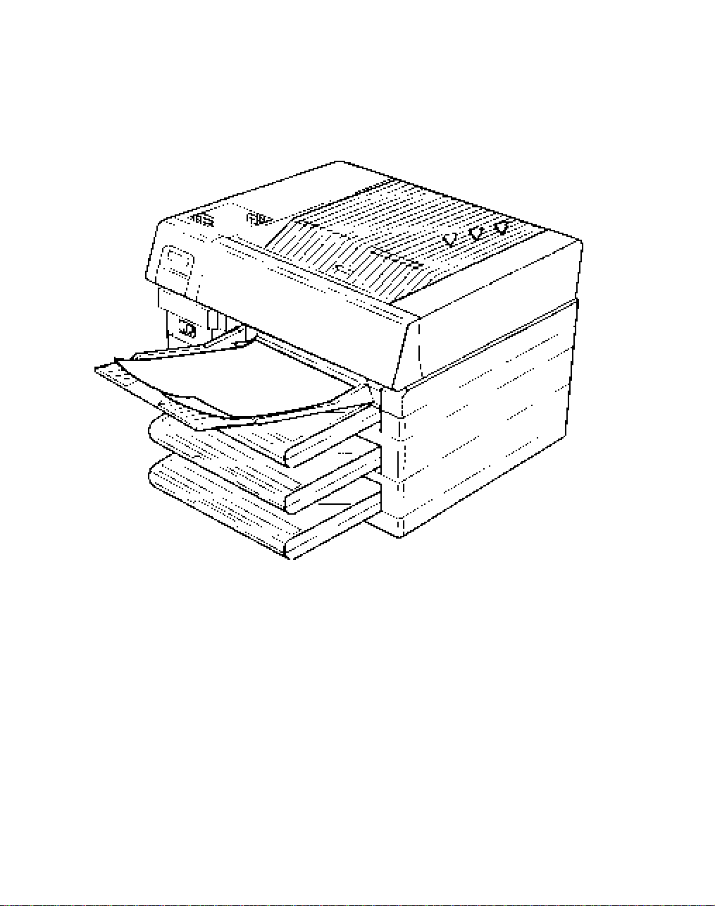
GENERAL
The printer consists of two major blocks—the controller and the print
engine. The controller functions as the interpreter of the source print data
and creates dot pattern information. The print engine prints the data based
upon the dot pattern information it receives from the controller.
The print engine includes the Laser Scanner Unit (laser/optical unit), EP
cartridge (developer, drum, toner, main charger), and paper feed
mechanisms. The print engine mechanisms are controlled by the DC
Controller.
This section of the manual describes the overall print process, Laser
Scanner Unit functions, and DC Controller functions. Locations of other
major parts and assemblies are provided as well as a brief description of
their functions.
NOTE: Many of the drawings in this manual show a two-tray model of the
LaserWriter Pro laser printer. All pictures of the two-tray model used in
this manual accurately represent the three-tray LaserWriter 810.
Apple Computer does not include a two-tray printer in the LaserWriter
810 product offering. If this manual is revised in the future the graphics
will be changed to reflect the three-tray configuration.
Page 6
LaserWriter Pro 810 Nov 93 Introduction/1-3
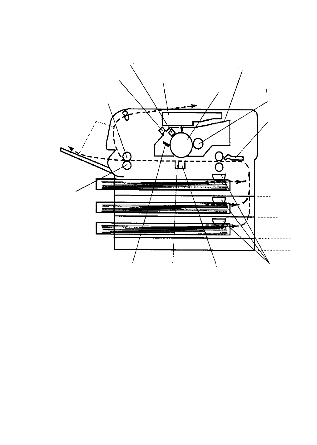
PRINTING PROCESS
MAIN
CHARGER
EP CARTRIDGE
MAGNETIC
ROLLER
TRANSPORT
CHUTE
PAPER PATH
ERASE LAMP
HEAT ROLLER
LASER SCANNER
UNIT
DRUM
PRESSURE
ROLLER
DRUM CLEANING
BLADE
DETACK
SAW
TRANSFER
CHARGER
FIRST TRAY
SECOND TRAY
THIRD TRAY
CONTROLLER
WAFER BOX
FEED
ROLLERS
Charging The main charger places a negative charge on the drum.
Exposure When an image signal is received, the laser emits light to the drum and
erases the negative charges to form an electrostatic latent image.
Developing The magnetic roller is covered by a thin film of magnetic toner. The toner
(negatively charged) is attracted to the latent image on the drum and forms
a visible image on the drum.
Transfer The transfer charger applies a positive charge to the bottom surface of
paper that transfers the toner image from the drum to the paper.
Separation The paper is separated from the drum by a combination of the detack saw
bias voltage and the paper's characteristics.
Fusing The toner image is fused to the paper by the heat and pressure applied by
the fuser rollers.
Cleaning The cleaning blade scrapes off any residual toner on the drum. At the same
time, the erase lamp transmits light to the drum and erases any residual
electrical charge. Following the cleaning process the print process starts
again from the charging cycle.
Page 7
LaserWriter Pro 810 Nov 93 Introduction/1-4
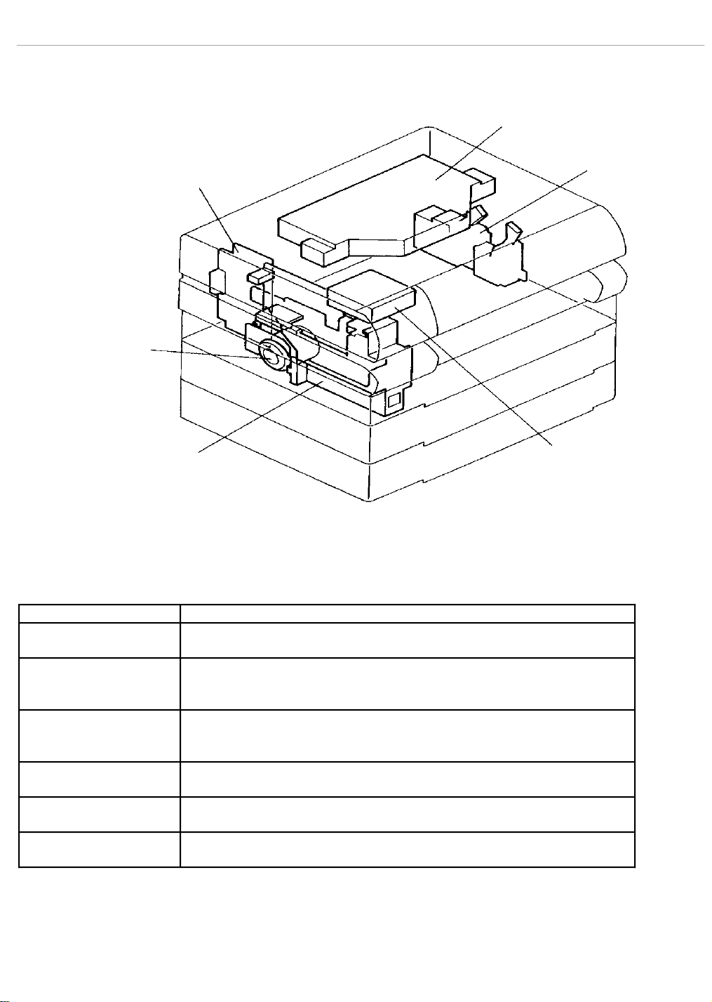
PART NAMES AND PART FUNCTIONS
LASER SCANNER
UNIT
HIGH VOLTAGE
DC CONTROLLER
MAIN MOTOR
POWER SUPPLY
LOW VOLTAGE
POWER SUPPLY
FUSER
FAN
ASSEMBLY
TABLE 1-1. PART NAMES AND FUNCTIONS
Name Main function
Main Motor Supplies the main mechanical drive for the printer. A fan on the
motor shaft cools the drive unit.
Laser Scanner Unit Receives a signal from the user system through the DC Controller
board, and converts the signal into a laser beam that is transmitted to
the drum to form an electrostatic latent image.
Low Voltage Power
Supply (LVPS)
Generates the +5, +15, and +24 voltages for the various printer
assemblies from the AC voltage input. Includes the main power
switch.
High Voltage Power
Supply (HVPS)
Generates the high DC/AC voltage for the transfer charger, main
charger, and magnetic roller.
DC Controller Controls the whole operation of the printer based on data from each
sensor and commands from the user system.
Fuser Fan Assembly Serves as the exhaust fan to prevent temperature in the printer from
rising.
Page 8
LaserWriter Pro 810 Nov 93 Introduction/1-5
PRE-REGISTRATION
SENSOR
TONER OUT
SENSOR
EP CARTRIDGE
SENSOR
INTERLOCK
SWITCH
RANSPORT ROLLER
CLUTCH
REGISTRATION
CLUTCH
PAPER FEED
SOLENOID
EXIT
SENSOR
TABLE 1-1. PART NAMES AND FUNCTIONS (CONTINUED)
ERASE LAMP
PAPER
OUT
SENSOR
FUSER THERMOSTAT
TEMPERATURE
SENSOR
CONTROL PANEL
ASSEMBLY
PAPER SIZE
SENSOR
POWER
SWITCH
Name Main function
Control Panel Assembly Displays the printer's operating status, error messages, and corrective
actions. The keypad is used for setting printer operating parameters.
Erase Lamp Light Emitting Diodes (LED) used to erase any residual charge on the drum.
Power Switch Turns AC power supply ON and OFF. The switch is part of the LVPS.
Cartridge Sensor Determines that the EP cartridge is seated correctly.
Temperature Sensor Detects the surface temperature of the heat roller and transmits a signal to
the DC Controller board to keep the heat roller temperature constant.
Fuser Thermostat Shuts off AC voltage to the fuser bulb when heater roller temperature gets
too high because of trouble with the temperature sensor, DC Controller, etc.
Paper Size Sensor Detects the size of a cassette installed in the printer by a combination of
“ON" and “OFF" signals transmitted by four independent sensors.
Paper Out Sensor Detects the absence of paper in the paper cassette.
Interlock Switch When the top cover is opened, the AC power for the fuser bulb, 24 VDC, and
15 VDC is interrupted and the printer stops immediately.
Exit Sensor Detects a paper jam at the paper exit.
Toner Empty Sensor Detects a no toner condition in the EP cartridge.
Pre-Registration Sensor Detects paper movement as well as no paper conditions when using the
manual feed guide.
Registration Clutch Rotates and stops the registration roller to position paper for a toner image
transfer from the drum.
Paper Feed Solenoid Electrically controls the rotation/stop operation of the feed roller that
moves the paper from a cassette.
Transport Roller Clutch Controls rotation/stop operation of the transport roller that moves the
paper from the cassette to the upper transport roller or registration roller.
Page 9
LaserWriter Pro 810 Nov 93 Introduction/1-6
EXPOSURE PROCESS
MIRROR 2
POLYGON
MIRROR
LENS 2
MIRROR 1
WINDOW
SOS
SENSOR
LENS 1
LASER DIODE
AND CYLINDER
LENS
DRUM
Except for the semiconductor, diode-type laser, the printer uses the same
Xerographic process as conventional copiers. When the printer receives a
print start signal from the I/O Controller, the laser diode starts emitting
light.
The laser beam from the laser diode is collimated by a cylinder lens before
being transmitted to the polygon mirror. The six-sided polygon mirror is
driven by the scanner motor that rotates at a constant speed (RPM). Each
rotation of the polygon mirror causes one scan line.
The laser beam, reflected by the polygon mirror, is transmitted to the
drum through lenses 1 and 2, mirrors 1 and 2, and the window. On the
right side of mirror 2 is a mirror for the Start of Scan (SOS) sensor. This
configuration keeps a constant scanning position for each scan line.
Page 10

LaserWriter Pro 810 Nov 93 Introduction/1-7
DC CONTROLLER FUNCTIONS
The DC Controller has the following main functions.
User System/Printer Communications
Receives video data synchronized with the video clock signal from the I/O
Controller and sends the video data synchronization signal and status signal
to the I/O Controller.
Sensor And Switch Signal Detection
Inputs signals from the sensors and switches that detect the status of the
printer before and during the print sequence.
Laser Scanner Unit Control
Monitors the scanner motor RPM and receives the SOS (Start of Scan)
signal to synchronize the start of laser beam scanning. Sends the video
print data to the Laser Scanner Unit in synchronization with the SOS signal.
Control Panel Display and Input
Displays error and status messages. Receives the input signals from the
keypad.
Print Sequence Control
Using sensor data and timers, it controls the print sequence of paper feed,
movement, and discharge.
Engine Self-Test and Diagnostics
The self-test print and diagnostic functions aid in the detection of print
engine errors and malfunctions.
LASER SCANNER UNIT BOARD FUNCTIONS
The board in the Laser Scanner Unit has the following functions:
Receives video data from the DC Controller board and uses it to control the
laser beam to form a latent image on the drum.
Controls the scanner motor so that it keeps rotating at a constant speed.
Page 11
LaserWriter Pro 810 Nov 93 Introduction/1-8
PRINTER SPECIFICATIONS
TABLE 1-2. PRINTER SPECIFICATIONS
ITEM DESCRIPTION
Type Desk top type
Page description
language/Emulation
Printing system Laser xerography system; Write black.
Print speed, maximum 20 sheets per minute
Resolution 300,400,600, and 800 dots/inch.
Paper feed Cassette paper feed
Paper cassettes,
standard
Optional cassette sizes Letter (8.4" x 11")
Paper sizes, manual feed Paper size: A4LEF, A4SEF, Executive, Legal, Letter LEF,
Paper weight Cassette feed: 52-82 g/m
Paper capacity Cassette: 250 sheets (64 g/m
Exit tray capacity Face up: 250 sheets (64 g/m
Printer size in millimeters Width Depth Height
Printer size in inches Width Depth Height
Printer weight 24.6 Kg, 54.23 lbs.
Warm-up time
Time to first print approximately 20 seconds
Noise level During operation: 53 dBA or less
Power supply 115 +10 VAC, 50/60 +2 Hz or
Power consumption Maximum 0.8 kW or less
Working Temperature
Humidity 15% to 85% RH non-condensing
Postscript Level 2 and HP LaserJet IIP
Manual paper feed
Multi media power feeder (Option)
Standard in 115 volt printers:
Letter (8.5" x 11")
Ledger (11" x 17")
Standard in 220/240 volt printers:
A3 (297 mm x 420 mm)
A4 (210 mm x 297 mm)
US Ledger (11" x 17")
Universal - all standard sizes
Letter SEF, Folio, B4, B5 and Invoice.
Envelope Size: Com-10, Monarch, C5, and DL
2
paper
Manual feed: 52-139 g/m2 paper or postcard stock 190
2
g/m
2
paper)
Multi media power feeder:
100 sheets (64 g/m
2
paper)
15 envelopes
2
letter -size paper
Face down: 250 sheets (64 g/m2 letter-size paper)
519 410 487
20.4 16.14 19.17
approximately 1 minute, at room temperature (22oC to 35oC
or 72oF to 95oF).
During standby: 40 dBA or less
220/240 VAC, 50/60
+2 Hz (International market)
10o to 35oC (50o to 95o F)
Page 12

LaserWriter Pro 810 Nov 93 Introduction/1-9
STORING CONSUMABLES
Paper should be stored in a cool, dry place. Keep it out of direct sunlight.
Avoid storing paper in an area with high humidity. When the printer isn't
going to be used for a long time, remove all the paper from the cassettes and
wrap it in the original wrapper.
EP Cartridges should be stored in a cool, dry place. Do not store them in
direct light. Avoid storing the EP cartridges in areas with high
temperature and humidity (0-35o C, 32-95o F and 10-80% relative
humidity). Do not store the cartridges on their sides or on end.
Be especially careful of conditions that could cause condensation to form on
the drum.
Page 13

LaserWriter Pro 810
Section 2: Setup Menu
Page 14
LaserWriter Pro 810 Nov 93 Setup Menu/2-2
GENERAL
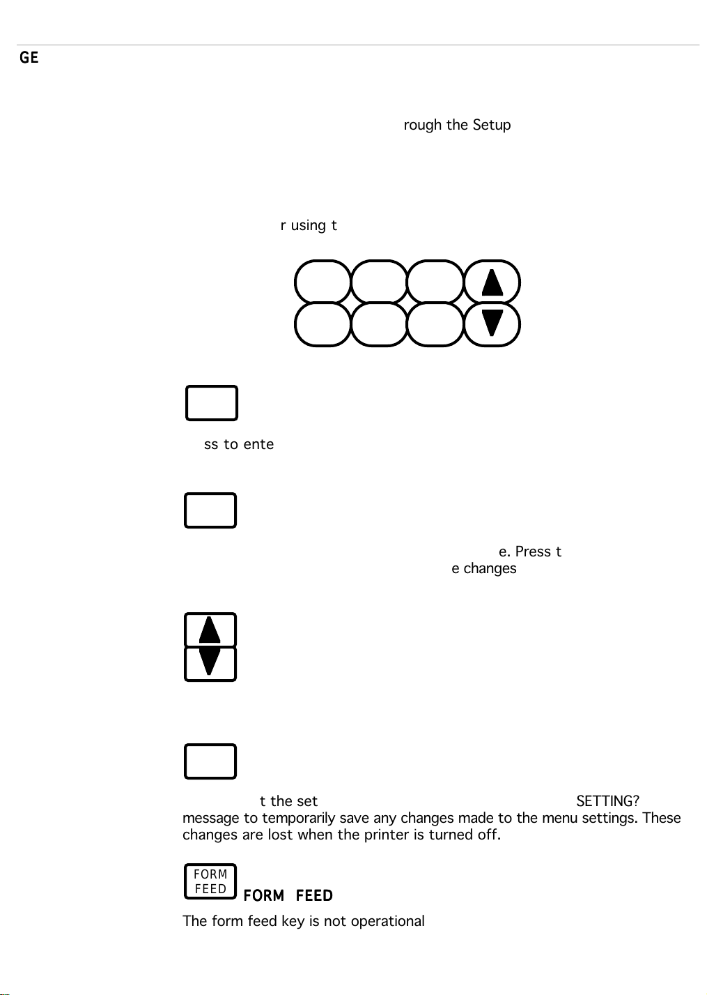
Setup Menu Keys
MENU KEY
ENTER KEY
ARROW KEYS
ONLINE KEY
FORM FEED
This section tells you how to use the Setup Menu to change the printer's
operating parameters. Operating parameters, such as input port, printer
type, and paper source are set through the Setup Menu.
The control panel keys that are used to get around in the setup menu are
illustrated and described below. See the User's Manual for more detailed
instructions for using the Setup Menu.
MENU
ONLINE
RESET
FORM
FEED
PRINT
STATUS
MENU
ENTER
Press to enter the Setup Menu after the printer is off-line. Press ENTER to
select a value.
ENTER
Press to select a menu item or a displayed value. Press to permanently save
any changes made to the setup menu. The changes are retained even if the
printer is turned off.
Press to scroll through a menu or sub-menu level.
ONLINE
Press to exit the setup menu. Press in response to a SAVE SETTING?
message to temporarily save any changes made to the menu settings. These
changes are lost when the printer is turned off.
FORM
FEED
The form feed key is not operational
Page 15
LaserWriter Pro 810 Nov 93 Setup Menu/2-3
Setup Menu Messages
TABLE 2-1. MENU MESSAGES
Setup Menu Description
The messages that you may encounter while using the setup menu are listed
and described in Table 2-1. Instructions for using the setup menu are in
the User's Manual.
Menu Message Description
SAVE SETTINGS?
ENTER=PERMANENT
ONLINE=TEMPORARY
TEMPORARY After setup menu changes have been
PERMANENT After setup menu changes have been
FACTORY SETUP?
ENTER=RESTORE
ONLINE=CANCEL
After changes have been made to the setup
menu, the ENTER and ONLINE prompts are
displayed alternately until the ONLINE or
ENTER key is pressed.
temporarily saved by pressing the ONLINE key,
this message is displayed.
permanently saved by pressing the ENTER key,
this message is displayed.
When RESTORE FACTORY SETUP is selected
from the Misc. menu, the ENTER and ONLINE
prompts are displayed alternately until the
ONLINE or ENTER key is pressed.
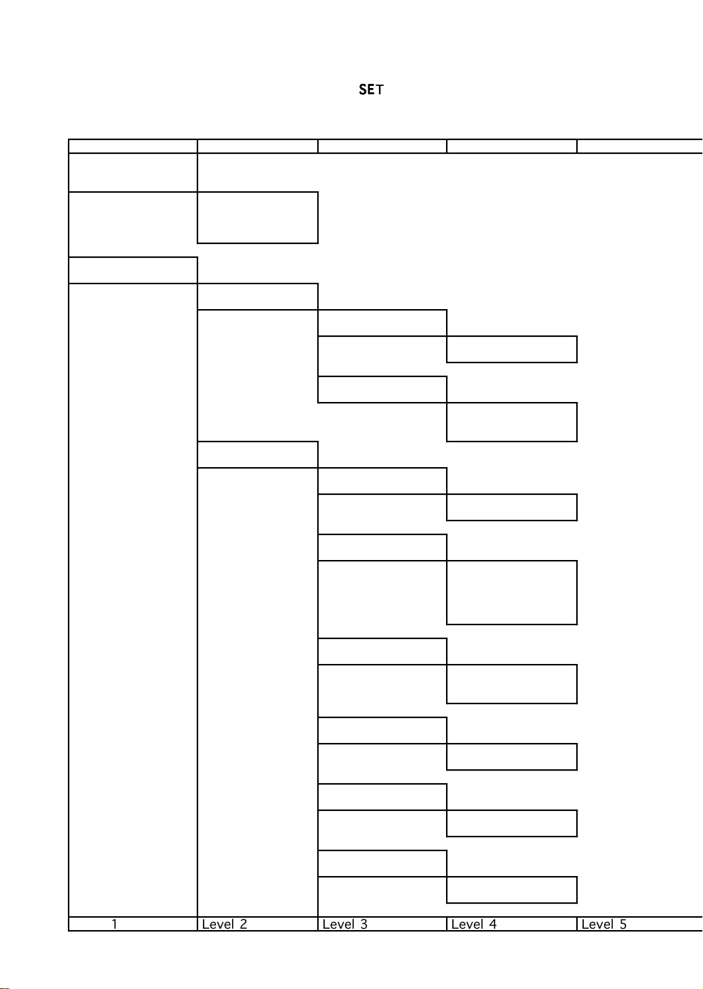
The Setup Menu for the printer works like many menu-driven software
packages. When you select an item in one menu, another menu may be
called up. You can continue to choose from each new menu until you get to
the selection you need.
The Setup Menu is illustrated in the diagram on the following pages. In the
diagram, the first item listed in a sub-menu is the factory default. After
changes have been made, the newly selected items or values are listed first
in the sub-menus. Each time you enter the Setup Menu, you are returned to
the menu or sub-menu that was displayed when you left it.
NOTE: An asterisk (*) appears in the message window when an item is
selected.
Page 16
LaserWriter Pro 810 Nov 93 Setup Menu/2-4
SETUP MENU
Level 1 Level 2 Level 3 Level 4 Level 5
MENU:
POSTSCRIPT
RESOLUTION
POSTSCRIPT
RESOLUTION
300, 400, 600,
800
MENU:
INPUT PORT
INPUT PORT
PARALLEL
PARALLEL
ENABLE
ENABLE
YES (N0)
PARALLEL
PRINTER TYPE
PRINTER TYPE
POSTSCRIPT
(LJETIIP)
INPUT PORT
RS232
RS232
ENABLE
ENABLE
YES (NO)
RS232
BAUD
BAUD
9600 (19200,
38400, 300, 600,
1200, 2400,
4800)
RS232
PARITY
PARITY
NONE (EVEN, ODD,
MARK, SPACE)
RS232
FLOW CONTROL
FLOW CONTROL
XON-XOFF (DTR)
RS232
STOP BITS
STOP BITS
1 (2)
RS232
DATA BITS
DATA BITS
8 (7)
Level 1 Level 2 Level 3 Level 4 Level 5
Page 17
LaserWriter Pro 810 Nov 93 Setup Menu/2-5
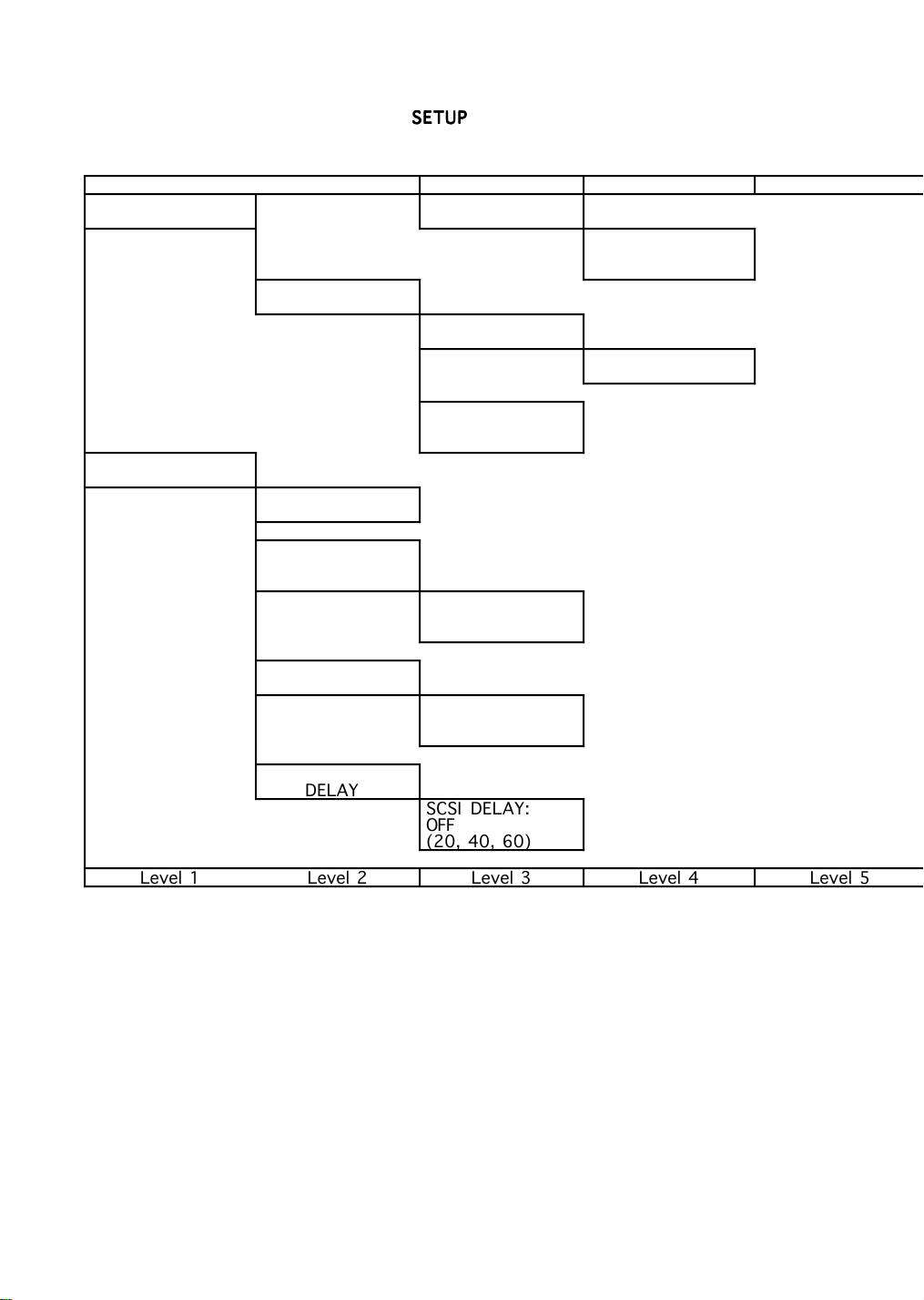
SETUP MENU (Continued)
Level 1 Level 2 Level 3 Level 4 Level 5
MENU:
INPUT PORT
INPUT PORT
LOCALTALK
MENU:
MISC
MISC RESTORE
FACTORY SETUP
MISC
EXIT JAM
REPRINT
RS232
PRINTER TYPE
PRINTER TYPE
POSTSCRIPT
(LJET IIP)
LOCALTALK
ENABLE
ENABLE
YES (NO)
PRINTER TYPE
POSTSCRIPT
(LJET IIP)
EXIT JAM
REPRINT DISABLE
(ENABLE)
MISC
START-UP PAGE
START-UP PAGE
ENABLE
(DISABLE)
MISC
SCSI DELAY
SCSI DELAY:
OFF
(20, 40, 60)
Level 1 Level 2 Level 3 Level 4 Level 5
Page 18
LaserWriter Pro 810 Nov 93 Setup Menu/2-6
SETUP MENU (Continued)
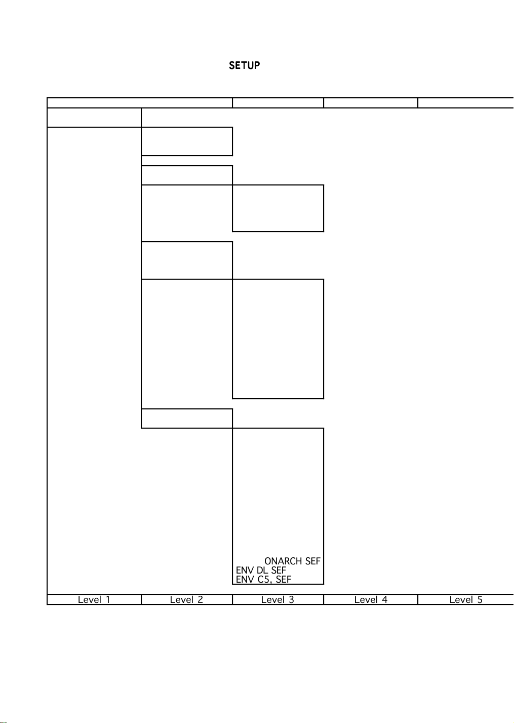
Level 1 Level 2 Level 3 Level 4 Level 5
MENU:
PAPER SOURCE
PAPER SOURCE
TRAY 1 (TRAY 2,
TRAY 3)
PAPER SOURCE
AUTO CASCADE
AUTO CASCADE
TRAY 1 & 2 & 3
(TRAY 1 & 2,
TRAY 1 & 3,
TRAY 2 & 3)
PAPER SOURCE
M-M PWR FEEDER
M-M PWR FEEDER
LETTER(8.5X11)
[LEGAL(8.5X14),
STAT(5.5X8.5),
EXEC(7.25X10.5),
FOLIO(210X330),
A4(210X297),
A5(210X148.5),
B5(182X257),
COM-10 ENV,
MONARCH ENV,
INT'L DL ENV,
INT'L C5 ENV]
PAPER SOURCE
MANUAL FEED
MANUAL FEED
LETTER, LEF
(LEDGER, SEF
LEGAL, SEF
STATEMENT, SEF
EXECUTIVE, SEF
LETTER, SEF
A4, SEF
A4, LEF
A5, SEF
A5, LEF
B5, LEF
B4, SEF
ENV COM-10, SEF
ENV MONARCH SEF
ENV DL SEF
ENV C5, SEF
Level 1 Level 2 Level 3 Level 4 Level 5
Page 19
LaserWriter Pro 810 Nov 93 Setup Menu/2-7
MENU POSTSCRIPT:/RESOLUTION
MENU:/INPUT PORT
The POSTSCRIPT RESOLUTION menu selects either 300, 400, 600 or 800
Dots-Per-Inch (DPI) resolution whenever POSTSCRIPT is the selected
printer type. Changing the resolution to 400, 600 or 800 (DPI) has no
effect when the printer type is LJET IIP (HP LaserJet IIP).
The printer has three Input/Output (I/O) connectors available. Since a
different system can be connected to each of the I/O connectors, the printer
can be shared by three user systems.
NOTE: PostScript documentation refers to the printer interfaces (I/O) as
channels. Port is another word sometimes used to refer to the interface
connectors and circuitry.
When the printer is shared by two or more systems, the interfacing
circuitry checks or polls each interface for incoming data. When data is
received on a port, that job is processed without interruption. Once the job
is completed, polling for incoming data resumes.
The Input Port Menu lets you disable an interface and/or set up the
required operating parameters that control communication between the
computer system(s) and the printer. The two serial channels can each be
set up with different protocols and baud rates.
The Input Port Menu also lets you select the PRINTER TYPE for each
channel. All three ports can be setup with PostScript as the Printer Type.
However, a combination of PostScript and HP LaserJet Series IIP can be
implemented. The printer type factory default for all three ports is
Postscript.
Page 20

LaserWriter Pro 810 Nov 93 Setup Menu/2-8
MENU:/MISC
MENU:/PAPER SOURCE
The Miscellaneous Menu is a selection of several miscellaneous features and
functions of the printer. It includes:
• resetting the printer to the factory defaults (RESTORE FACTORY
SETUP)
• enabling the EXIT JAM REPRINT function
• disabling the START-UP PAGE function
• setting a delay time for a hard disk drive
• selecting the language for the control panel messages
RESTORE FACTORY SETUP can be used whenever the printer needs to be
reset to the factory defaults. This is useful if changes have been made that
do not seem to be functioning as planned.
Three factory defaults, one of which is selectable from the Setup Menu,
cannot be changed by the RESTORE FACTORY SETUP. The three are Display
Language, printer name, and page count.
The EXIT JAM REPRINT function enables the printer to reprint a page that
may be in the exit area when a jam occurs. This means that two pages,
instead of one, are reprinted. Because reprinting two pages uses more of
the printer memory, the function can be turned off to free more memory.
The START-UP PAGE function can be turned off after the printer is set up.
However, printing the start-up page is a good way to be sure that the
printer is operating correctly.
The SCSI DELAY function sets the length of time the printer will wait for a
hard disk drive to come ready during the power on cycle. Some disk drives
may take longer than the printer to power up. The delay avoids the
possible problem of the printer not seeing the disk drive.
A DISPLAY LANGUAGE menu is displayed when this feature is supported. It
lets you select the language that is used for the messages that are displayed
on the control panel. English is the default.
The PAPER SOURCE Menu is used to select a paper source. If the printer
model has only one cassette and the multi media power feeder is not
installed, only manual feed and tray one are displayed on the Setup Menu.
Manual feed and the multi-media power feeder both have sub-menus for
selecting the paper and envelope sizes.
The Auto Cascade function can be enabled in this menu. For this feature to
work, each cassette (tray) must contain the same paper size.
Page 21

LaserWriter Pro 810
Section 3: Preventive Maintenance
Page 22

LaserWriter Pro 810 Nov 93 Preventive Maintenance/3-2
GENERAL
This section describes a preventive maintenance procedure that should be
carried out whenever other service is required by the user. By checking the
printer on a service call, you can instruct the user about printer care and
possibly prevent future problems. The procedure can be completed in 10
minutes or less.
PREVENTIVE MAINTENANCE PROCEDURE
1 . Record the total number of pages fed through the printer to date.
• Turn the printer on while pressing the DOWN arrow key to enter
the diagnostic mode.
• Press the DOWN arrow key once again to enter the total counter
display. The LED displays a cumulative count in six digits.
• Estimate the life of the consumables from the counter reading.
2 . Check overall printer operation by doing the following:
• Turn off the printer.
• Turn the printer on while pressing the ENTER key to enter the
print test mode.
NOTE: If the multi media power feeder is installed, make several
prints using it as the paper source. See Section 5 for more
information about using the print test mode.
• Make several prints in the test print mode.
• Listen for abnormal noises as the test printout is printing.
• Check the test printout for print quality problems.
3 . Check the transfer charger assembly.
CAUTION: Be careful not to break the charger and guide wires
while cleaning the transfer charger.
• Take out the transfer charger and clean it with a brush or a dry
cloth.
• Be sure to clean the transport rollers.
CAUTION: Do not expose the drum to light for more than five
minutes. Print quality can deteriorate.
• If the transfer charger is badly soiled, clean it with a cloth
slightly moistened with water and then with a dry cloth.
4 . Check the fuser heat roller cleaner for paper dust and dirt build-up.
• Remove the fuser heat roller cleaner from the fuser.
• Remove deposits of paper dust and toner from the cleaning felt. A
firm bristled brush may help.
Page 23

LaserWriter Pro 810 Nov 93 Preventive Maintenance/3-3
5. Check the registration roller and transport chute.
• Clean them with a brush and dry cloth.
• If they are badly soiled, clean them with a cloth slightly moistened
with water and then with a dry one.
NOTE: Do not leave any rollers dirty. Dirty rollers can cause
print quality and paper handling problems.
6 . Check the fan exhaust inlet.
• If the top cover is removed during maintenance, use a brush to
remove the dirt, toner, and paper dust from the fan exhaust.
7. Recheck printer operation.
• Make several more test prints.
• Check again for print quality, paper feed, and abnormal noises.
8 . Turn the printer off and on to enter the normal mode.
9 . Make a final print test by sending data from the users system.
1 0 . Report to the user any potential or real problems that you found.
Page 24

LaserWriter Pro 810
Section 4: Take Apart Procedures
Page 25

LaserWriter Pro 810 Nov 93 Take Apart/4-2
GENERAL
Section 4 does not cover all printer parts. Some parts are omitted because
they require neither adjustment nor special consideration in removing or
installing them. If no Take Apart procedure is provided in this section,
carefully check an installed part before removing it. For plug and
connector locations, see the figures and table at the end of this section.
CAUTION: Turn the printer off and unplug the power cord before starting
any Take Apart procedure.
Recommended Tools
The only tools needed to remove or install any assembly are:
1 . Screwdrivers, Philips head, several sizes and lengths (magnetized
would be useful).
2. Chip puller.
3. Blade screwdriver (various sizes).
4. Wire cutters.
Page 26

LaserWriter Pro 810 Nov 93 Take Apart/4-3
LIST OF TAKE APART PROCEDURES
POWER CORD COVER 4 - 5
TOP COVER 4 - 7
FRONT COVER 4 - 8
LEFT COVER 4 - 9
RIGHT COVER 4-10
REAR COVER 4-11
ELECTRICAL BOX COVER 4-12
TRANSFER CHARGER/DETACK SAW ASSEMBLY 4-13
PAPER TRANSFER UNIT 4-14
REGISTRATION CLUTCH 4-15
PRE-REGISTRATION SENSOR 4-16
TRANSPORT CLUTCH (TRAY 1) 4-17
PAPER FEED ROLLER ASSEMBLY 4-18
PAPER FEED SOLENOID (TRAY 1) 4-19
PAPER OUT SENSOR (TRAY 1) 4-20
PAPER SIZE SENSOR (TRAY 1) 4-21
OUTER TURN-CHUTE ASSEMBLY 4-22
INNER TURN-CHUTE ASSEMBLY 4-23
TRANSPORT CHUTE ASSEMBLY 4-24
FUSER UNIT 4-25
FUSER BULB 4-27
FUSER THERMOSTAT 4-28
FUSER TEMPERATURE SENSOR 4-29
PAPER EXIT SENSOR 4-30
OUTER EXIT-CHUTE ASSEMBLY 4-31
DIRECTION CHUTE 4-32
INNER EXIT-CHUTE 4-33
EXIT ROLLER ASSEMBLY 4-34
BELT (FUSER AREA) 4-35
LASER SCANNER UNIT 4-36
ERASE ASSEMBLY 4-37
TONER SENSOR 4-38
TONER SENSOR BRACKET 4-39
Page 27

LaserWriter Pro 810 Nov 93 Take Apart/4-4
EP CARTRIDGE SENSOR BRACKET 4-40
EP CARTRIDGE SENSOR 4-41
FUSER FAN 4-42
DRIVE UNIT 4-43
LOW VOLTAGE POWER SUPPLY (LVPS) 4-45
CONTROL PANEL ASSEMBLY 4-46
HIGH VOLTAGE POWER SUPPLY (HVPS) 4-48
DC CONTROLLER 4-49
I/O CONTROLLER 4-50
FEEDER UNIT 4-52
LOWER CHUTE ASSEMBLY 4-53
PAPER OUT SENSOR (TRAY 2 & 3) 4-54
PAPER FEED ROLLER ASSEMBLY 4-55
PAPER FEED SOLENOID (TRAY 2 & 3) 4-56
PAPER SIZE SENSOR (TRAY 2 & 3) 4-57
OUTER TURN-CHUTE ASSEMBLY 4-58
INNER TURN-CHUTE ASSEMBLY 4-59
MULTI MEDIA POWER FEEDER 4-60
TOP COVER (MULTI MEDIA POWER FEEDER) 4-61
TRAY ASSEMBLY (MULTI MEDIA POWER FEEDER) 4-62
MULTI MEDIA FEEDER PCB 4-63
PAPER FEED SENSOR (MULTI MEDIA POWER FEEDER) 4-64
PAPER OUT SENSOR (MULTI MEDIA POWER FEEDER) 4-65
MOTOR ASSEMBLY (MULTI MEDIA POWER FEEDER) 4-66
FEED ROLLER ASSEMBLY (MULTI MEDIA POWER FEEDER) 4-67
TAKE-AWAY ROLLER ASSEMBLY(MULTI MEDIA POWER FEEDER) 4-68
RETARD ASSEMBLY (MULTI MEDIA POWER FEEDER) 4-69
FAX CARTRIDGE INSTALLATION 4-70
PLUG/CONNECTOR LOCATIONS 4-73
Page 28

LaserWriter Pro 810 Nov 93 Take Apart/4-5
POWER CORD COVER
Removal To remove the power cord cover:
1 . Carefully pull the rear end of the power cord cover away from the side
of the printer. Use a coin, or similar object, if needed, to pry the
cover loose.
2 . Slide the whole cover toward the front of the printer until it can be
removed.
POWER
CORD
COVER
FIGURE 4-1. POWER CORD COVER REMOVAL
Installation To install the power cord cover:
1 . Lay the power cord along the base of the printer. Be sure the power
cord is secured by the hooks provided
POWER
CORD
HOOKS
FIGURE 4-2. POWER CORD COVER INSTALLATION
COVER
Page 29

LaserWriter Pro 810 Nov 93 Take Apart/4-6
2 . Attach the front of the power cord cover to the printer.
3 . Carefully press on the rear end of the cover to lock it in place.
Page 30
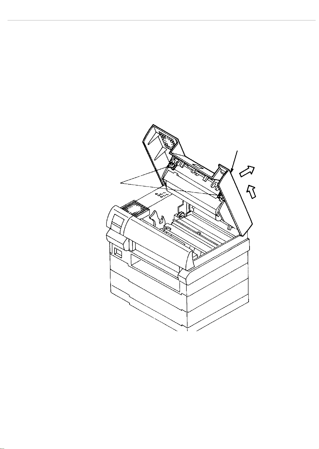
LaserWriter Pro 810 Nov 93 Take Apart/4-7
TOP COVER
Removal To remove the top cover:
1 . Turn off the printer and unplug the power cord from the electrical
outlet.
2. Open the top cover. Remove the EP cartridge and put it in a safe place.
3. Raise the top cover as far as possible.
4 . Loosen the two front screws with the silver flanges.
5 . Push back on the top cover and then lift it upward to remove it.
TOP
COVER
COVER
SCREWS
FIGURE 4-3. TOP COVER REMOVAL
Installation To install the top cover:
Reverse the removal procedure.
CAUTION: Be sure that the hooks on the rear of the cover are engaged with
the frame.
Page 31

LaserWriter Pro 810 Nov 93 Take Apart/4-8
FRONT COVER
Removal To remove the front cover:
1 . Remove the two screws with silver flanges from the front cover.
2 . Push down on the front cover as you move it toward you. The lower
edge must be unhooked from the frame. Use a thin tool such as a T-pin
or a jewler's screwdriver to unhook the tabs.
FRONT
COVER
SCREWS
FIGURE 4-4. FRONT COVER REMOVAL
Installation To install the front cover:
Reverse the removal procedure.
FRONT
COVER
Page 32

LaserWriter Pro 810 Nov 93 Take Apart/4-9
LEFT COVER
Removal To remove the left cover:
1. Remove the power cord cover. Disconnect the power cord.
2. Remove the top cover.
3 . Remove the front cover.
4 . Remove the four screws with silver flanges from the left cover.
5. While pulling the left cover assembly toward you, carefully pull out
on the front edge of the cover to unhook it from the power switch.
6 . Carefully move the left cover assembly toward the left to remove it.
LEFT
COVER
SCREWS
LEFT COVER
FIGURE 4-5. LEFT COVER REMOVAL
Installation To install the left cover:
Reverse the removal procedure.
LEFT COVER
SCREW (FRONT)
Page 33

LaserWriter Pro 810 Nov 93 Take Apart/4-10
RIGHT COVER
Removal To remove the right cover:
1. Remove the top cover.
2 . Remove the front cover.
3 . Remove the outer exit-chute assembly.
4 . Remove the three screws with silver flanges from the right cover.
5 . Lift the right cover and carefully pull it straight out and away from
the frame.
RIGHT
COVER
SCREWS
RIGHT COVER
SCREW
FIGURE 4-6. RIGHT COVER REMOVAL
Installation To install the right cover:
Reverse the removal procedure.
RIGHT
COVER
Page 34

LaserWriter Pro 810 Nov 93 Take Apart/4-11
REAR COVER
Removal To remove the rear cover:
1. Remove the power cord cover.
2 . Remove the manual feed tray or the multi media power feeder.
3. Remove the top cover.
4 . Remove the front cover.
5 . Remove the left cover.
6 . Remove the right cover.
7 . Remove the remaining two screws with silver flanges that attaches the
rear cover to the frame.
8 . Pull the rear cover straight out and away from the frame.
REAR
COVER
REAR COVER
SCREWS
FIGURE 4-7. REAR COVER REMOVAL
Installation To install the rear cover:
Reverse the removal procedure.
Page 35

LaserWriter Pro 810 Nov 93 Take Apart/4-12
ELECTRICAL BOX COVER
Removal To remove the electrical box cover:
1. Remove the power cord cover.
2. Remove the top cover.
3 . Remove the front cover.
4 . Remove the left cover.
5. Remove the fuser fan.
6 . Remove the seven screws with silver flanges from the electrical box
cover.
7 . Move the electrical box cover straight out and away from the printer.
BEFORE REMOVING THE ELECTRICAL
BOX COVER SCREWS, NOTE THE
LOCATION OF THE TWO
HOLES FOR THE LEFT
COVER SCREWS.
COVER
SCREWS
GROUND
WIRE
TERMINAL
COVER
SCREWS
FIGURE 4-8. ELECTRICAL BOX COVER REMOVAL
Installation To install the electrical box cover:
1 . Reverse the removal procedure. Be sure that the electrical box cover
screws are not installed in the left cover screw holes.
CAUTION: Be sure the ground wire is attached when installing the electrical
box cover mounting screws.
ELECTRICAL BOX COVER
Page 36

LaserWriter Pro 810 Nov 93 Take Apart/4-13
TRANSFER CHARGER/DETACK SAW ASSEMBLY
Removal To remove the transfer charger/detack saw assembly:
1. Open the top cover.
2 . Raise the right side of the transfer charger/detack saw assembly
slightly. See Figure 4- 9
3 . Slide the transfer charger/detack saw assembly to the right until it
can be lifted from the printer.
TRANSFER
CHARGER/DETACK
SAW ASSEMBLY
FIGURE 4-9. TRANSFER CHARGER/DETACK SAW ASSEMBLY REMOVAL
Installation To install the transfer charger/detack saw assembly:
Reverse the removal procedure.
Page 37

LaserWriter Pro 810 Nov 93 Take Apart/4-14
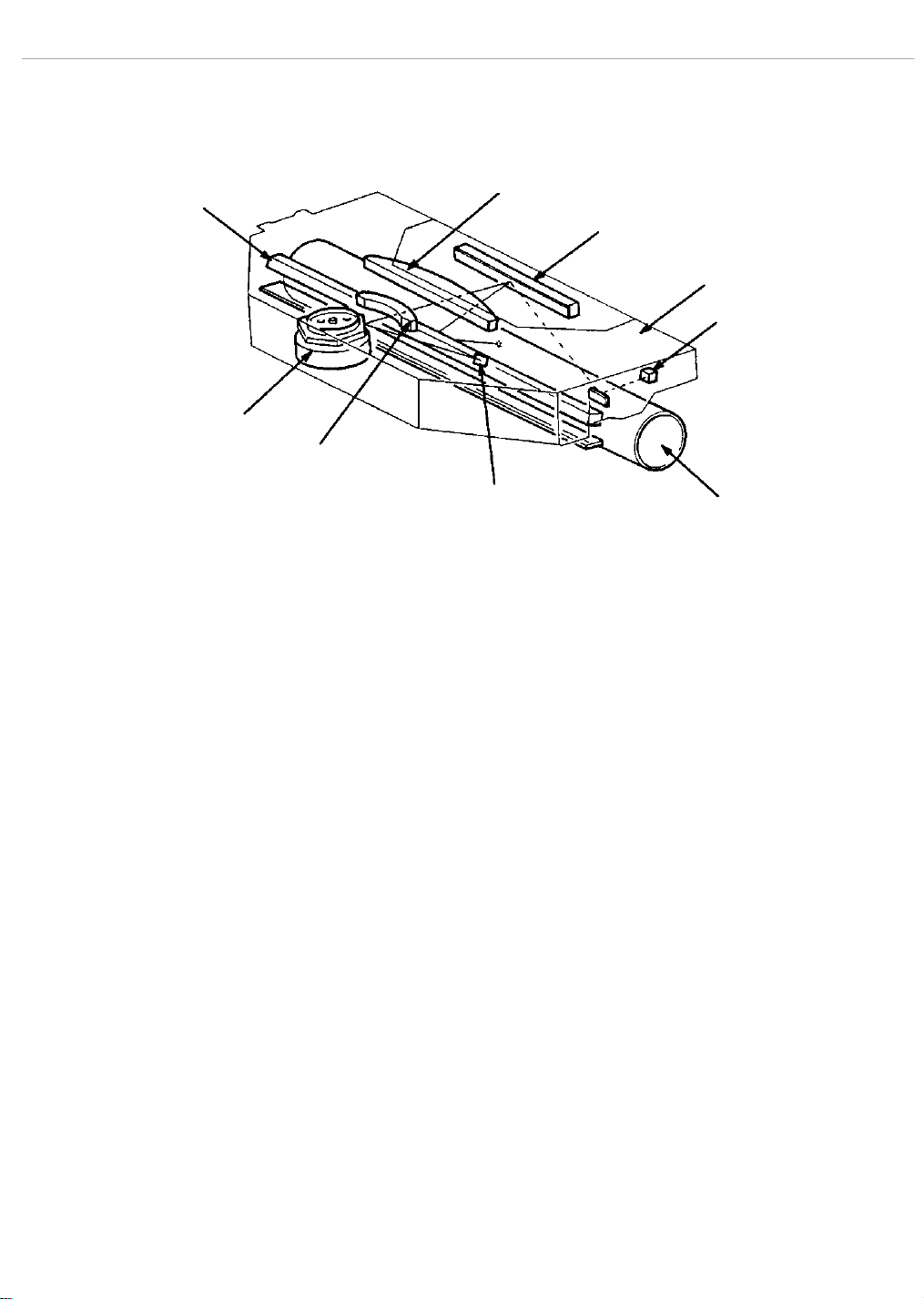
PAPER TRANSFER UNIT
Removal To remove the Paper Transfer Unit:
1. Open the top cover. Remove the EP cartridge and keep it in a safe
place.
2 . Remove the transfer charger/detack saw assembly.
3 . Remove the registration clutch connector P/J9 from the DC
Controller.
4 . Remove the two black screws from the inlet chute to remove it.
5 . Remove the two screws with silver flanges from the Paper Transfer
Unit.
6 . Raise the Paper Transfer Unit.
7 . Move the Paper Transfer Unit forward in the direction of arrow.
CAUTION: To prevent the ground plate on the left side from dropping, hold it
securely when removing the Paper Transfer Unit.
INLET
CHUTE
SCREW
PAPER
TRANSFER
UNIT
SCREWS
FIGURE 4-10. PAPER TRANSFER UNIT REMOVAL
Installation To install the Paper Transfer Unit:
Reverse the removal procedure.
INLET
CHUTE
INLET
CHUTE
SCREW
PAPER
TRANSFER
UNIT
NOTE: Before securing the Paper Transfer Unit, position the ground plate
to the left and route the ground wire to the right. Be sure that the unit
rests on the frame.
Page 38

LaserWriter Pro 810 Nov 93 Take Apart/4-15
REGISTRATION CLUTCH
Removal To remove the registration clutch:
1. Open the top cover. Remove the EP cartridge and keep it in a safe
place.
2 . Remove the transfer charger/detack saw assembly.
3 . Remove the Paper Transfer Unit.
4 . Remove the C-ring from the gear and slide the gear from the frame.
5. Disconnect the transport clutch connector P/J51 and the preregistration sensor connector P/J52.
6 . Remove the E-ring from the registration clutch and slide the clutch
out of the frame.
C-RING
GEAR
PAPER TRANSFER
UNIT
E-RING
REGISTRATION
CLUTCH
FIGURE 4-11. REGISTRATION CLUTCH REMOVAL
Installation To install the registration clutch:
Reverse the removal procedure.
Page 39

LaserWriter Pro 810 Nov 93 Take Apart/4-16
PRE-REGISTRATION SENSOR
Removal To remove the pre-registration sensor:
1. Open the top cover. Remove the EP cartridge, and keep it in a safe
place.
2 . Remove the transfer charger/detack saw assembly.
3 . Remove the Paper Transfer Unit.
4. To remove the pre-registration sensor, release the four clips that
secure the pre-registration sensor to the Paper Transfer Unit.
PRE-REGISTRATION
SENSOR
FIGURE 4-12. PRE-REGISTRATION SENSOR REMOVAL
Installation To install the pre-registration sensor:
Reverse the removal procedure.
PAPER TRANSFER
UNIT
Page 40

LaserWriter Pro 810 Nov 93 Take Apart/4-17
TRANSPORT CLUTCH (TRAY 1)
Removal To remove the transport clutch:
1. Open the top cover. Remove the EP cartridge, and keep it in a safe
place.
2 . Remove the transfer charger/detack saw assembly.
3 . Remove the Paper Transfer Unit.
4 . Remove the C-ring from the gear and slide it from its shaft.
5. Disconnect the transport clutch connector P/J51.
6. Remove the E-ring from the transport clutch.
7. Lift the transport roller shaft out of the Paper Transfer Unit frame.
8. Slide the transport clutch from the roller shaft.
C-RING
E-RING
FIGURE 4-13. TRANSPORT CLUTCH REMOVAL
Installation To install the transport clutch:
Reverse the removal procedure.
TRANSPORT
ROLLER
PAPER TRANSFER
UNIT
Page 41

LaserWriter Pro 810 Nov 93 Take Apart/4-18
PAPER FEED ROLLER ASSEMBLY
Removal To remove the feed roller assembly:
1. Open the top cover. Remove the EP cartridge, and keep it in a safe
place.
2 . Remove the transfer charger/detack saw assembly.
3 . Remove the Paper Transfer Unit.
4 . Remove the KL clip on the right side of the feed roller shaft.
5 . Move the feed roller assembly to the right then raise it until it can be
removed from the printer.
FIGURE 4-14. FEED ROLLER ASSEMBLY REMOVAL
Installation To install the feed roller assembly:
Reverse the removal procedure.
CAUTION: Be sure the flange side of KL clip faces inward when it is
installed.
KL CLIP
PAPER FEED
ROLLER
ASSEMBLY
Page 42

LaserWriter Pro 810 Nov 93 Take Apart/4-19
PAPER FEED SOLENOID (TRAY 1)
Removal To remove the paper feed solenoid:
1. Open the top cover. Remove the EP cartridge and keep it in a safe
place.
2 . Remove the transfer charger/detack saw assembly.
3 . Remove the Paper Transfer Unit.
4 . Remove the feed roller assembly.
5 . Remove the electrical box cover.
6 . Remove connector P/J8 from the DC Controller.
7 . Remove the screw with the black flange from the paper feed solenoid.
8 . Lift the paper feed solenoid up and out of the printer base.
MOUNTING
SCREW
FIGURE 4-15. PAPER FEED SOLENOID REMOVAL
Installation To install the paper feed solenoid:
Reverse the removal procedure.
PAPER
FEED
SOLENOID
Page 43

LaserWriter Pro 810 Nov 93 Take Apart/4-20
PAPER OUT SENSOR (TRAY 1)
Removal To remove the paper out sensor:
1. Open the top cover. Remove the EP cartridge and keep it in a safe
place.
2 . Remove the transfer charger/detack saw assembly.
3 . Remove the Paper Transfer Unit.
4. Disconnect P/J42.
5 . Release the four clips securing the paper out sensor, and remove it.
PAPER
OUT
SENSOR
FIGURE 4-16. PAPER OUT SENSOR REMOVAL
Installation To install the paper out sensor:
Reverse the removal procedure.
Page 44

LaserWriter Pro 810 Nov 93 Take Apart/4-21
PAPER SIZE SENSOR (TRAY 1)
Removal To remove the paper size sensor:
1. Open the top cover. Remove the EP cartridge and keep it in a safe
place.
2. Remove the power cord cover.
3. Remove the top cover.
4 . Remove the front cover.
5 . Remove the left cover.
6 . Remove the fuser assembly.
7 . Remove the electrical box cover.
8 . Remove the low voltage power supply. See page 4-43 for
instructions.
9 . Use a small blade screwdriver to release the three clips securing the
paper size sensor. See Figure 4-17.
10 . Disconnect P/J10 from the DC Controller.
1 1. Carefully pull the sensor harness from the printer to remove the
paper size sensor.
PAPER SIZE
SENSOR
FIGURE 4-17. PAPER SIZE SENSOR REMOVAL
Installation To install the paper size sensor:
Reverse the removal procedure.
Page 45

LaserWriter Pro 810 Nov 93 Take Apart/4-22
OUTER TURN-CHUTE ASSEMBLY
Removal To remove the outer turn-chute assembly:
1. Open the top cover. Remove the EP cartridge and keep it in a safe
place.
2 . Remove the transfer charger/detack saw assembly.
3 . Remove the Paper Transfer Unit.
4. Remove the power cord cover.
5. Remove the top cover.
6 . Remove the front cover.
7 . Remove the left cover.
8 . Remove the right cover.
9 . Remove the rear cover.
10 . Remove the right and left springs from the outer turn-chute
assembly. Be sure to save the washers.
1 1. Carefully pull the outer turn-chute assembly out of the back of the
printer.
SPRING
OUTER
TURN-CHUTE
ASSEMBLY
FIGURE 4-18. OUTER TURN-CHUTE ASSEMBLY
SPRING
Installation To install the outer turn-chute assembly:
Reverse the removal procedure.
CAUTION: Be sure to install the washers for the turn-chute assembly.
Page 46

LaserWriter Pro 810 Nov 93 Take Apart/4-23
INNER TURN-CHUTE ASSEMBLY
Removal To remove the inner turn-chute assembly:
1. Open the top cover. Remove the EP cartridge and keep it in a safe
place.
2 . Remove the transfer charger/detack saw assembly.
3 . Remove the Paper Transfer Unit.
4. Remove the power cord cover.
5. Remove the top cover.
6 . Remove the front cover.
7 . Remove the left cover.
8 . Remove the right cover.
9 . Remove the rear cover.
1 0. Remove the outer turn-chute assembly.
1 1 . Remove the right and left springs from each side of the inner turn-
chute assembly.
1 2. Slide the inner turn-chute to the left or right to free the shaft and
remove the turn-chute.
SPRING
INNER
TURN-CHUTE
ASSEMBLY
SPRING
FIGURE 4-19. INNER TURN-CHUTE ASSEMBLY REMOVAL
Installation To install the inner turn-chute assembly:
Reverse the removal procedure.
Page 47

LaserWriter Pro 810 Nov 93 Take Apart/4-24
TRANSPORT CHUTE ASSEMBLY
Removal To remove the transport chute assembly:
1. Open the top cover. Remove the EP cartridge and keep it in a safe
place.
2. Loosen the two captive screws on each side of the transport chute
assembly.
3. Lift the transport chute assembly out of the printer.
CAPTIVE
SCREWS
FIGURE 4-20. TRANSPORT CHUTE ASSEMBLY REMOVAL
Installation To install the transport chute assembly:
Reverse the removal procedure.
Page 48

LaserWriter Pro 810 Nov 93 Take Apart/4-25
FUSER UNIT
Removal To remove the fuser unit:
1. Open the top cover. Remove the EP cartridge and keep it in a safe
place.
CAUTION: The fuser unit is very hot when the printer is first turned off.
Wait for the fuser unit to cool before continuing.
2 . Remove the transfer charger/detack saw assembly.
3 . Remove the transport chute assembly.
4 . Disconnect the three plugs located under the fan.
FAN
P62 FUSER BULB
P31 TEMPERATURE SENSOR
P32 EXIT SENSOR
FIGURE 4-21. FUSER UNIT HARNESS REMOVAL
5 . Loosen the two captive screws on the fuser unit.
FIGURE 4-22. FUSER UNIT REMOVAL
NOTE: When lifting the fuser unit out of the printer, do not press on the
roller cleaner cover.
6 . Hold the fuser unit by the two metal flanges sticking out of the top, and
lift it diagonally out of the printer.
Page 49

LaserWriter Pro 810 Nov 93 Take Apart/4-26
FIGURE 4-23. FUSER UNIT REMOVAL
Installation To install the fuser unit:
1 . Set the fuser unit down on the guides and align the inner sides.
2 . Make sure the fuser is seated correctly. There should be no space
between the fuser unit screws and the printer frame.
0mm
FIGURE 4-24. FUSER UNIT INSTALLATION
CAUTION: If the fuser unit is not perfectly seated inside of the guides, paper
jam problems can occur.
3 . Tighten the two captive screws on the fuser unit. Check to be sure the
unit is secure.
4 . Plug the three connectors from the fuser unit wires into the
connectors under the fan. See Figure 4-21.
5. Install the transfer charger.
6 . Install the transport chute/detack saw assembly.
7. Close the top cover.
8. Plug in the printer.
Page 50

LaserWriter Pro 810 Nov 93 Take Apart/4-27
FUSER BULB
Removal To remove the fuser bulb:
1. Open the top cover. Remove the EP cartridge and keep it in a safe
plate.
2 . Remove the fuser unit.
3 . Remove the screw with a gold flange from the right end of the roller
cleaner cover, and remove it.
4 . Remove the roller cleaner.
5 . Remove the two screws with black flanges from the outer cover, and
remove it.
6 . Carefully pull outward on the metal clamp securing the fuser bulb.
7 . Slide the fuser bulb out of the heat roller.
FUSER
UNIT
FIGURE 4-25. FUSER BULB REMOVAL
Installation To install the fuser bulb:
Reverse the removal procedure.
FUSER
BULB
CLAMP
FUSER
BULB
Page 51

LaserWriter Pro 810 Nov 93 Take Apart/4-28
FUSER THERMOSTAT
Removal To remove the fuser thermostat:
1. Open the top cover. Remove the EP cartridge and keep it in a safe
place.
2 . Remove the fuser unit.
3 . Remove a screw with a gold flange from the right side of roller
cleaner cover assembly and remove it.
4 . Remove the roller cleaner.
5 . Remove the right and left screws with black flanges from the outer
cover, and remove it.
6 . Remove the fuser bulb.
7 . Remove the four screws with black flanges from the inner cover
assembly, and remove it.
8 . Remove the two gold screws from the fuser thermostat to remove it.
INNER
COVER
SCREWS
INNER COVER
ASSEMBLY
THERMOSTAT
FIGURE 4-26. FUSER THERMOSTAT REMOVAL
Installation To install the fuser thermostat:
Reverse the removal procedure.
THERMOSTAT
SCREWS
INNER
COVER
SCREWS
FUSER
BASE
Page 52

LaserWriter Pro 810 Nov 93 Take Apart/4-29
FUSER TEMPERATURE SENSOR
Removal To remove the fuser temperature sensor:
1. Open the top cover. Remove the EP cartridge and keep it in a safe
place.
2 . Remove the fuser unit.
3 . Remove the screw with a gold flange from the right end of the roller
cleaner cover assembly, and remove it.
4 . Remove the roller cleaner.
5 . Remove the right and left screws with black flanges from the outer
cover, and remove it.
6 . Remove the fuser bulb.
7 . Remove four screws with black flanges from the inner cover, and
remove it.
8 . Remove the gold screw from the temperature sensor, and remove it.
TEMPERATURE
SENSOR
SENSOR
SCREW
FIGURE 4-27. FUSER TEMPERATURE SENSOR REMOVAL
Installation To install the fuser temperature sensor:
Reverse the removal procedure.
INNER COVER
ASSEMBLY
Page 53

LaserWriter Pro 810 Nov 93 Take Apart/4-30
PAPER EXIT SENSOR
Removal To remove the paper exit sensor:
1. Open the top cover. Remove the EP cartridge and keep it in a safe
place.
2 . Remove the fuser unit.
3 . Remove the screw with a gold flange from the right end of the roller
cleaner cover assembly, and remove it.
4 . Remove the roller cleaner.
5 . Remove right and left screws with black flanges from the outer cover,
and remove it.
6 . Remove the fuser bulb.
7 . Remove the four screws with black flanges from the inner cover
assembly and remove it.
8 . Remove the gold screw from the paper exit sensor to remove it.
EXIT
SENSOR
SENSOR
SCREW
FIGURE 4-28. PAPER EXIT SENSOR REMOVAL
Installation To install the paper exit sensor:
Reverse the removal procedure.
INNER COVER
ASSEMBLY
Page 54

LaserWriter Pro 810 Nov 93 Take Apart/4-31
OUTER EXIT-CHUTE ASSEMBLY
Removal To remove the outer exit-chute:
1 . Open the outer exit-chute assembly.
2 . Carefully pull outward on the right and left bearings until the outer
exit-chute assembly can be removed.
BEARING
BEARING
OUTER EXIT-CHUTE ASSEMBLY
FIGURE 4-29. OUTER EXIT-CHUTE REMOVAL
Installation To install the outer exit-chute assembly:
Reverse the removal procedure.
Page 55

LaserWriter Pro 810 Nov 93 Take Apart/4-32
DIRECTION CHUTE
Removal To remove the direction chute:
1 . Remove the outer exit-chute assembly.
2 . Remove the E-ring and spring from the direction chute to remove it.
DIRECTION
CHUTE
E-RING
SPRING
FIGURE 4-30. DIRECTION CHUTE REMOVAL
Installation To install the direction chute:
Reverse the removal procedure.
Page 56

LaserWriter Pro 810 Nov 93 Take Apart/4-33
INNER EXIT-CHUTE
Removal To remove the inner exit-chute:
1 . Remove the outer-exit chute assembly.
2 . Remove the direction chute.
3 . Remove screws with silver flanges from each side of the inner exit-
chute inner to remove it.
SCREWS
FIGURE 4-31. INNER EXIT-CHUTE REMOVAL
Installation To install the inner exit-chute:
Reverse the removal procedure.
INNER
EXIT-CHUTE
Page 57

LaserWriter Pro 810 Nov 93 Take Apart/4-34
EXIT ROLLER ASSEMBLY
Removal To remove the exit roller assembly:
1 . Remove the outer exit-chute assembly.
2 . Remove the direction chute.
3. Remove the inner exit-chute.
4 . Remove the fuser fan. See page 4-40 for instructions.
5 . Remove the belt on the right end of the exit roller assembly. See the
next procedure for instructions.
6 . Remove the E-rings from each end of the roller shaft.
7 . Slide the pulley and bearing off of the right end of the exit roller
shaft.
8 . Slide the exit roller shaft to the left and remove the exit roller
assembly from the printer.
BEARING
E-RING
BEARING
FIGURE 4-32. EXIT ROLLER ASSEMBLY
Installation To install the exit roller assembly:
Reverse the removal procedure.
PULLEY
E-RING
BELT
LOCATION
Page 58

LaserWriter Pro 810 Nov 93 Take Apart/4-35
BELT (FUSER AREA)
Removal To remove the belt:
1. Remove the top cover.
2 . Remove the front cover.
3 . Remove the right cover.
4 . Remove the outer exit chute assembly.
5 . Remove the E-ring.
6 . Slide the idler shaft inward.
7. Remove the belt.
BELT
IDLER
SHAFT
FIGURE 4-33. FUSER AREA BELT REMOVAL
Installation To install the belt:
Reverse the removal procedure.
E-RING
Page 59

LaserWriter Pro 810 Nov 93 Take Apart/4-36
LASER SCANNER UNIT
Removal To remove the Laser Scanner Unit:
1. Remove the top cover.
2 . Remove right and left screws with silver flanges from the laser
scanner unit.
3. Disconnect P21 from J21.
4 . Open the laser scanner unit shield and lift the laser scanner unit out
of the printer.
CAUTION: Keep the Laser Scanner Unit in a safe place.
MOUNTING
SCREW
LASER
SCANNER
UNIT
FIGURE 4-34. LASER SCANNER UNIT REMOVAL
MOUNTING
SCREW
Installation To install the Laser Scanner Unit:
Reverse the removal procedure.
Page 60

LaserWriter Pro 810 Nov 93 Take Apart/4-37
ERASE ASSEMBLY
Removal To remove the erase assembly:
1. Open the top cover. Remove the EP cartridge and keep it in a safe
place.
2. Remove the top cover.
3 . Remove the two black screws from the erase assembly.
4 . Disconnect P22 from J22. Remove the erase assembly.
MOUNTING
SCREW
ERASE ASSEMBLY
FIGURE 4-35. ERASE ASSEMBLY REMOVAL
Installation To install the erase assembly:
Reverse the removal procedure.
MOUNTING
SCREW
Page 61

LaserWriter Pro 810 Nov 93 Take Apart/4-38
TONER SENSOR
Removal To remove the toner sensor:
1. Open the top cover. Remove the EP cartridge and keep it in a safe
place.
2. Remove the top cover.
3. Disconnect P23 from J23.
4 . Release the four clamps that secure the toner sensor to the bracket to
remove the toner sensor.
TONER
SENSOR
CLAMPS
FIGURE 4-36. TONER SENSOR REMOVAL
Installation To install the toner sensor:
Reverse the removal procedure.
Page 62

LaserWriter Pro 810 Nov 93 Take Apart/4-39
TONER SENSOR BRACKET
Removal To remove the toner sensor bracket:
1. Open the top cover. Remove the EP cartridge and keep it in a safe
place.
2. Remove the top cover.
3. Remove the toner sensor.
4 . Remove the E-ring from the left end of the shaft.
5 . Move the shaft to the left.
6 . Remove the toner sensor bracket.
CAUTION: Keep the spring in a safe place for the installation procedure.
TONER SENSOR BRACKET
SPRING
E-RING
FIGURE 4-37. TONER SENSOR BRACKET REMOVAL
Installation To install the toner sensor bracket:
Reverse the removal procedure.
Page 63

LaserWriter Pro 810 Nov 93 Take Apart/4-40
EP CARTRIDGE SENSOR BRACKET
Removal To remove the EP cartridge sensor bracket:
1. Open the top cover. Remove EP cartridge and keep it in a safe place.
2. Remove the top cover.
3 . Remove the E-ring from the end of the shaft.
4 . Slide the shaft to the right.
5 . Slide the EP cartridge sensor bracket out of the printer.
6. Remove the EP Cartridge sensor if needed.
CAUTION: Do not lose or discard the spring. It must be installed again.
E-RING
SPRING
EP
CARTRIDGE
SENSOR
BRACKET
FIGURE 4-38. EP CARTRIDGE SENSOR BRACKET REMOVAL
Installation To install the EP cartridge sensor bracket:
Reverse the removal procedure.
Page 64

LaserWriter Pro 810 Nov 93 Take Apart/4-41
EP CARTRIDGE SENSOR
Removal To remove the EP cartridge sensor:
1. Open the top cover. Remove the EP cartridge and keep it in a safe
place.
2. Remove the top cover.
3 . Remove the EP cartridge sensor bracket.
4. Disconnect P24 from J24.
5 . Release the upper and lower clips that secure the sensor to the EP
cartridge sensor bracket.
6. Remove the EP cartridge sensor.
EP
CARTRIDGE
SENSOR
FIGURE 4-39. EP CARTRIDGE SENSOR REMOVAL
Installation To install the EP cartridge sensor:
Reverse the removal procedure.
Page 65

LaserWriter Pro 810 Nov 93 Take Apart/4-42
FUSER FAN
Removal To remove the fuser fan:
1 . Remove the three long, gold screws from the fuser fan.
2. Disconnect P33 from J33.
3 . Remove the fan wire harness from the wire clamp.
4. Remove the fan cover and fuser fan.
MOUNTING
SCREWS
FUSER FAN
FIGURE 4-40. FUSER FAN REMOVAL
Installation To install the fuser fan:
Reverse the removal procedure.
Page 66

LaserWriter Pro 810 Nov 93 Take Apart/4-43
DRIVE UNIT
Removal To remove the drive unit:
1. Remove the power cord cover.
2. Remove the top cover.
3 . Remove the front cover.
4 . Remove the left cover.
5. Remove the fuser fan.
6 . Remove the electrical box cover.
7 . Remove the control panel assembly.
8 . Remove the following connectors (see “Plug/Connector Locations" at
the end of this section):
•P/J61 (on the Low Voltage Power Supply PCB)
•P/J73 (on the Drive Unit PCB)
•P/J62 (Fuser Bulb)
•P/J31 (Temperature Sensor)
•P/J32(Exit Sensor)
•P/J1, P/J4, P/J7, P/J8, P/J9, and P/J10 (DC Controller)
9. Remove the screw that secures the cables to the DC Controller
connectors P/J81, P/J82, P/J83, P/J84, P/J91, P/J92, P/J93,
and P/J94, and the green ground wire.
1 0 . Remove the four screws with silver flanges from the side frame
assembly and remove it from the printer.
SIDE
FRAME
ASSEMBLY
PRINTER
FRAME
SIDE
FRAME
SCREWS
SIDE FRAME
SCREW
FIGURE 4-41. SIDE FRAME ASSEMBLY REMOVAL
Page 67

LaserWriter Pro 810 Nov 93 Take Apart/4-44
CAUTION: While doing the following step, be careful NOT to tilt the unit and
let the drive gears fall from their shafts.
11. Remove the five gold screws and the black hex head screw from the
drive unit to remove it from the side frame assembly.
PRINTER
FRAME
DRIVE
UNIT
DRIVE UNIT
SCREWS
FIGURE 4-42. DRIVE UNIT REMOVAL
Installation To install the drive unit:
1 . Reverse the installation procedure. See “Plug/Connector Locations" at
the end of this section for wire and cable routing.
Page 68

LaserWriter Pro 810 Nov 93 Take Apart/4-45
LOW VOLTAGE POWER SUPPLY (LVPS)
Removal To remove the low voltage power supply:
1. Open the top cover. Remove the EP cartridge and keep it in a safe
place.
2. Remove the power cord cover.
3. Remove the top cover.
4 . Remove the front cover.
5 . Remove the left cover.
6 . Remove the electrical box cover.
7. Remove the fuser fan.
8 . Remove the control panel assembly.
CAUTION: To avoid damage, hold the Low Voltage Power Supply PCB while
disconnecting P61 from J61.
9 . Disconnect P/J61 and P/J62 from the Low Voltage Power Supply
PCB.
1 0 . Remove the four screws from the low voltage power supply to remove
it.
LOW VOLTAGE
POWER SUPPLY
MOUNTING
SCREWS
FIGURE 4-43. LOW VOLTAGE POWER SUPPLY REMOVAL
Installation To install the low voltage power supply:
1 . Reverse the removal procedure.
See “Plug/Connector Locations" at
the end of this section for help in routing and connecting cables.
CAUTION: When installing the fuser fan, be sure the its harness is secured
by the wire clamp.
CAUTION: The connectors P2 and P3 on the DC Controller must be connected
and routed prior to replacement of the Low Voltage Power Supply.
MOUNTING
SCREW
Page 69

LaserWriter Pro 810 Nov 93 Take Apart/4-46
CONTROL PANEL ASSEMBLY
Removal To install the control panel assembly:
1. Open the top cover. Remove the EP cartridge and keep it in a safe
place.
2. Remove the power cord cover.
3. Remove the top cover.
4 . Remove the front cover.
5 . Remove the left cover.
6 . Remove the electrical box cover.
7. Remove the fuser fan.
NOTE: The keypad should remain open while doing the following steps.
8. Open the control panel keypad.
9 . Remove the three screws with silver flanges from the control panel
assembly.
CONTROL
PANEL
ASSEMBLY
MOUNTING
SCREWS
FIGURE 4-44. CONTROL PANEL ASSEMBLY REMOVAL
1 0. Remove the low voltage power supply.
CAUTION: Note the location and routing of the wire harness before
disconnecting and removing it.
1 1 . Disconnect the plugs from the DC Controller connectors P/J2 and
P/J3.
12. Carefully free the wire harness from the printer frame before
removing the control panel assembly.
Installation To install the control panel assembly:
1 . Reverse the removal procedure.
See “Plug/Connector Locations" at
the end of this section for help in routing and connecting cables.
Page 70

LaserWriter Pro 810 Nov 93 Take Apart/4-47
NOTE: Wire leads for the back-light break easily from the LCD panel.
During installation, be careful to position the Control Panel PCB correctly.
If the Control Panel PCB is not aligned properly the wires may be damaged.
CAUTION: When installing the fuser fan, be sure the its harness is secured
by the wire clamp.
Page 71

LaserWriter Pro 810 Nov 93 Take Apart/4-48
HIGH VOLTAGE POWER SUPPLY (HVPS)
Removal To remove the high voltage power supply:
1. Open the top cover. Remove the EP cartridge and keep it in a safe
place.
2. Remove the top cover.
3 . Remove the front cover.
4 . Remove the outer exit chute assembly.
5 . Remove the right cover assembly.
6 . Remove the transfer charger/ detack saw assembly.
7 . Remove the Paper Transfer Unit.
8 . Remove the feed roller assembly.
9. Disconnect P41 from J41.
1 0 . Remove the screw with a silver flange from the high voltage power
supply.
1 1 . Move the high voltage power supply to the left then lift it out of the
printer base as shown by the arrows in Figure 4-46.
FIGURE 4-45. HIGH VOLTAGE POWER SUPPLY REMOVAL
Installation To install the high voltage power supply:
Reverse the removal procedure.
HIGH VOLTAGE
POWER SUPPLY
(HVPS)
MOUNTING
SCREW
Page 72

LaserWriter Pro 810 Nov 93 Take Apart/4-49
DC CONTROLLER
Removal To remove the DC Controller:
1. Open the top cover. Remove the EP cartridge and keep it in a safe
place.
2. Remove the power cord cover.
3. Remove the top cover.
4 . Remove the front cover.
5 . Remove the left cover.
6 . Remove the electrical box cover.
7 . Remove the following connectors:
•P/J61 (on the Low Voltage Power Supply PCB)
•P/J73 (on the Drive Unit PCB)
•P/J1, P/J2, P/J3, P/J4, P/J7, P/J8, P/J9, P/J10 P12 (DC
Controller)
•Remove connectors P/J81, P/J82, P/J83, and P/J84, P/J91,
P/J92, P/J93, and P/J94.
8 . Remove the two screws with silver flanges from the back panel and
remove it.
9 . To remove the DC Controller, remove the two screws with silver
flanges that attach it to the back panel.
BACK PANEL
BACK PANEL
SCREWS
DC
CONTROLLER
SCREWS
DC
CONTROLLER
PCB
4-46. DC CONTROLLER REMOVAL
Installation To install the DC Controller:
FIGURE
Reverse the removal procedure.
See “Plug/Connector Locations" at the end
of this section for help in routing and connecting cables.
CAUTION: When reinstalling the DC Controller, make sure that cables are
installed in the connectors P81-P84, P91-94 and P12.
Page 73

LaserWriter Pro 810 Nov 93 Take Apart/4-50
I/O CONTROLLER
Removal To remove the I/O Controller:
1 . Remove the screw from the front corner of the wafer box cover.
2 . Remove the screw from the back corner of the wafer box cover.
3 . Remove the four screws that attach the I/O Controller to the interface
bracket.
INTERFACE
BRACKET
SCREWS
FIGURE 4-47. WAFER BOX COVER REMOVAL
WAFER BOX
COVER SCREWS
4 . Holding onto to the wafer box cover, slide the I/O Controller out of the
printer until the power and ribbon cables can be reached.
5. Note the cable connector directions and disconnect the power and
ribbon cables.
6 . Slide the I/O Controller completely out of the wafer box.
7 . If replacing the I/O Controller, remove the two screws that attach the
PCB to the wafer box brackets.
8 . Remove the I/O Controller from the wafer box bracket.
CAUTION: When the I/O Controller board is removed, the printer can
collapse preventing the I/O board from seating correctly. This collapse can
result from moving or applying pressure to the top of the printer while the
I/O board is removed.
Page 74

LaserWriter Pro 810 Nov 93 Take Apart/4-51
POWER CABLE
PLUG (J7)
I/O CONTROLLER
WAFER BOX
RIBBON
CABLE PLUG
(J6)
FIGURE 4-48. I/O CONTROLLER REMOVAL
Installation To install the I/O Controller:
1 . Position the I/O Controller on the wafer box cover brackets with the
edge of the I/O Controller Board in the slots.
2 . Install the two mounting screws.
3 . Slide the I/O Controller into the right guide in the wafer box.
4 . Continue to insert the I/O Controller into the wafer box until it slides
into the left guide that begins about halfway.
5 . Plug in the power and ribbon cables when the I/O Controller Board is
almost fully inserted.
6. Fully insert the I/O Controller Board.
7 . Install two screws on each side of the wafer box cover.
8 . Install the four screws removed from the interface bracket.
Page 75

LaserWriter Pro 810 Nov 93 Take Apart/4-52
FEEDER UNIT
Removal To remove the feeder unit:
1. Remove the power cord cover.
2. Remove the top cover.
3 . Remove the front cover.
4 . Remove the left cover.
5 . Remove the right cover.
6 . Remove the electrical box cover.
7 . Remove the four screws with silver flanges that attach the feeder unit
to the print engine body.
8 . Remove the following connectors:
•P/J81, P/J82, P/J83, P/J84.
•P/J91, J/J92, P/J93, P/J94.
9 . Remove the screw that attaches the two feeder unit ground wires to the
print engine. It is located in front of the DC Controller.
10 . Lift the print engine from the feeder unit.
1 1 . To separate the two feeder units, remove the four screws that attach
the upper feeder unit to the lower feeder unit.
1 2 . Lift the upper feeder unit off of the lower feeder unit, if needed.
MOUNTING
SCREWS
UPPER
FEEDER
UNIT
LOWER
FEEDER
UNIT
MOUNTING
SCREWS
FIGURE 4-49. FEEDER UNIT REMOVAL
Installation To install the feeder unit:
Reverse the removal procedure.
Page 76

LaserWriter Pro 810 Nov 93 Take Apart/4-53
LOWER CHUTE ASSEMBLY
Removal To remove the lower chute assembly from a feeder unit:
1 . Remove the feeder unit.
2 . Remove the five screws from the lower chute assembly.
3 . Lift and remove it.
LOWER CHUTE
ASSEMBLY
MOUNTING
SCREWS
MOUNTING
SCREWS
FIGURE 4-50. LOWER CHUTE ASSEMBLY REMOVAL
Installation To install the lower chute assembly in a feeder unit:
Reverse the removal procedure.
Page 77

LaserWriter Pro 810 Nov 93 Take Apart/4-54
PAPER OUT SENSOR
Removal To remove the paper out sensor from a feeder unit:
1 . Remove the feeder unit.
2 . Release the four spring clips that attach the paper out sensor to the
lower chute assembly.
PAPER OUT SENSOR
FIGURE 4-51. PAPER OUT SENSOR (FEEDER UNITS)
Installation To install the paper out sensor in a feeder unit:
Reverse the removal procedure.
Page 78

LaserWriter Pro 810 Nov 93 Take Apart/4-55
PAPER FEED ROLLER ASSEMBLY
Removal To remove the paper feed roller assembly from a feeder unit:
1 . Remove the feeder unit.
2 . Remove the lower chute assembly.
3 . Lift the paper feed roller assembly out of the feeder unit.
PAPER FEED
ROLLER
ASSEMBLY
FIGURE 4-52. PAPER FEED ROLLER ASSEMBLY (FEEDER UNITS)
Installation To install the paper feed roller assembly in a feeder unit:
Reverse the removal procedure.
Page 79

LaserWriter Pro 810 Nov 93 Take Apart/4-56
PAPER FEED SOLENOID (TRAYS 2 & 3)
Removal To remove a paper feed solenoid from a feeder unit:
1 . Remove the feeder unit.
2 . Remove the lower chute assembly.
3 . Remove the paper feed roller assembly.
4. Remove the screw with a black flange that attaches the paper feed
solenoid to the feeder unit.
5. Slide the paper feed solenoid to one side and lift it out of the feeder
unit.
PAPER FEED
MOUNTING
SCREW
SOLENOID
4-53. PAPER FEED SOLENOID REMOVAL (FEEDER UNITS)
Installation To install a paper feed solenoid in a feeder unit:
Reverse the removal procedure.
Page 80

LaserWriter Pro 810 Nov 93 Take Apart/4-57
PAPER SIZE SENSOR (TRAYS 2 & 3)
Removal To remove the paper size sensor from a feeder unit:
1 . Remove the feeder unit.
2 . Using a screwdriver release the three clamps that attach the paper
size sensor to the side frame of the feeder unit.
PAPER SIZE
SENSOR
FIGURE 4-54. PAPER SENSOR REMOVAL (FEEDER UNITS)
Installation To install the paper size sensor in a feeder unit:
Reverse the removal procedure.
Page 81

LaserWriter Pro 810 Nov 93 Take Apart/4-58
OUTER TURN-CHUTE ASSEMBLY
Removal To remove the outer turn-chute assembly from a feeder unit:
1 . Remove the feeder unit.
2 . Remove the lower chute assembly.
3 . Remove the spring on each side of the outer turn-chute assembly.
4 . Move the turn chute assembly downward and out of the feeder unit.
NOTE: To remove the outer turn chute assembly from the top tray of a 2-
tray feeder unit, separate the two units first.
SPRING
OUTER TURN-CHUTE ASSEMBLY
FIGURE 4-55. OUTER TURN-CHUTE ASSEMBLY REMOVAL (FEEDER UNITS)
SPRING
Installation To install the outer turn-chute assembly in a feeder unit:
Reverse the removal procedure.
Page 82

LaserWriter Pro 810 Nov 93 Take Apart/4-59
INNER TURN-CHUTE ASSEMBLY
Removal To remove the inner turn-chute assembly from a feeder unit:
1 . Remove the feeder unit.
2 . Remove the lower chute assembly.
3 . Remove the spring from each side of the inner turn-chute assembly.
4 . Push the shaft of the inner turn chute assembly inward to remove it
from the feeder unit.
INNER TURN-CHUTE ASSEMBLY
FIGURE 4-56. INNER TURN-CHUTE ASSEMBLY REMOVAL (FEEDER UNITS)
Installation To install an inner turn chute assembly in a feeder unit:
Reverse the removal procedure.
Page 83

LaserWriter Pro 810 Nov 93 Take Apart/4-60
MULTI MEDIA POWER FEEDER
Removal To remove the multi media power feeder:
1 . Turn off the printer and disconnect the multi media power feeder
interface cable from its connector on the printer.
2. Loosen the knobs on both sides on the bottom of the multi media power
feeder sensor.
FIGURE 4-57 MULTI MEDIA POWER FEEDER REMOVAL
3. Remove the guide chute from the manual feed guide.
FIGURE 4-58 MULTI MEDIA POWER FEEDER REMOVAL
Installation To install the multi media power feeder:
Reverse the removal procedure.
Page 84

LaserWriter Pro 810 Nov 93 Take Apart/4-61
TOP COVER (MULTI MEDIA POWER FEEDER)
Removal To remove the top cover of the multi media power feeder:
1 . Remove the multi media power feeder as required.
2 . Remove the two long screws (black, with hexagonal flanges) on both
sides of the bottom of the multi media power feeder.
3. Remove the top cover.
SCREW
MULTI MEDIA
POWER FEEDER
BOTTOM VIEW
FIGURE 4-59 TOP COVER REMOVAL (MULTI MEDIA POWER FEEDER)
SCREW
Installation To install the multi media power feeder top cover:
Reverse the removal procedure.
Page 85

LaserWriter Pro 810 Nov 93 Take Apart/4-62
TRAY ASSEMBLY (MULTI MEDIA POWER FEEDER)
Removal To remove the multi media power feeder tray assembly:
1 . Remove the multi media power feeder as required.
2. Remove the top cover.
3 . Carefully pull outward on both sides of the tray assembly to clear the
bearings and remove the tray.
TRAY ASSEMBLY
FIGURE 4-60 TRAY ASSEMBLY (MULTI MEDIA POWER FEEDER) REMOVAL
Installation To install the tray assembly:
Reverse the removal procedure.
CAUTION: When installing the tray assembly, hold the paper guide closed
so that it does not interfere with the paper size switch.
Page 86

LaserWriter Pro 810 Nov 93 Take Apart/4-63
MULTI MEDIA POWER FEEDER PCB
Removal To remove the Multi Media Power Feeder PCB:
1 . Remove the multi media power feeder, as required.
2. Remove the top cover.
3 . Remove the tray assembly to prevent possible damage to it.
4. Disconnect the plugs from connectors CN1 to CN5 on the PCB.
5 . Pull the Multi Power Feeder PCB straight up and out of the feeder.
MULTI MEDIA
POWER FEEDER PCB
FIGURE 4-61 MULTI MEDIA POWER FEEDER PCB REMOVAL
Installation To install the Multi Media Power Feeder PCB:
Reverse the removal procedure.
Page 87

LaserWriter Pro 810 Nov 93 Take Apart/4-64
PAPER FEED SOLENOID (MULTI MEDIA POWER FEEDER)
Removal To remove the paper feed solenoid:
1 . Remove the multi media power feeder as required.
2. Remove the top cover.
3 . Remove the tray assembly to prevent possible damage to it.
4 . Remove the black screws with square flanges that attach connector
CN3 and the paper feed solenoid to the multi media power feeder
frame.
5. Remove the paper feed solenoid.
PAPER FEED
SOLENOID
FIGURE 4-62 PAPER FEED SOLENOID (MULTI MEDIA POWER FEEDER) REMOVAL
Installation To install the paper feed solenoid:
Reverse the removal procedure.
SCREWS
Page 88

LaserWriter Pro 810 Nov 93 Take Apart/4-65
PAPER OUT SENSOR
Removal To remove the paper out sensor:
1 . Remove the multi media power feeder from the printer.
2. Remove the top cover.
3 . Release the four clips that attach the paper out sensor to the multi
media power feeder base.
4. Remove the paper out sensor.
PAPER OUT
SENSOR
4-63 PAPER OUT SENSOR (MULTI MEDIA POWER FEEDER) REMOVAL
Installation To install the paper out sensor:
Reverse the removal procedure.
FIGURE
Page 89

LaserWriter Pro 810 Nov 93 Take Apart/4-66
MOTOR ASSEMBLY (MULTI MEDIA POWER FEEDER)
Removal To remove the motor assembly:
1 . Remove the multi media power feeder from the printer.
2. Remove the top cover.
3. Remove the Multi Media Power Feeder PCB.
4. Remove the two black screws with hexagonal flanges that attaches the
motor assembly to the frame.
MOTOR
ASSEMBLY
FIGURE 4-64 MOTOR ASSEMBLY (MULTI MEDIA POWER FEEDER) REMOVAL
Installation To install the motor assembly:
Reverse the removal procedure.
Page 90

LaserWriter Pro 810 Nov 93 Take Apart/4-67
FEED ROLLER ASSEMBLY (MULTI MEDIA POWER FEEDER)
Removal To remove the feed roller assembly:
1 . Remove the multi media power feeder as required.
2. Remove the top cover.
3. Remove the feed solenoid
4 . Remove the E-rings on each end of the feed roller shaft.
5 . Move the feed roller shaft to the left until it is free of the cam then
lift it out of the printer.
E-RING
FEED ROLLER
ASSEMBLY
E-RING
FIGURE 4-65 FEED ROLLER ASSEMBLY (MULTI MEDIA POWER FEEDER)
REMOVAL
Installation To install the feed roller assembly:
Reverse the removal procedure.
CAUTION: Be sure the cam is positioned correctly when installing the feed
roller assembly.
CAM
Page 91

LaserWriter Pro 810 Nov 93 Take Apart/4-68
TAKE-AWAY ROLLER ASSEMBLY (MULTI MEDIA POWER FEEDER)
Removal To remove the take away roller assembly:
1 . Remove the multi media power feeder as required.
2. Remove the top cover.
3. Remove the black screw with a hexagonal flange that secures the
ground wire.
4 . Remove the connector CN2 from the motor assembly, connector CN3
from the paper feed solenoid, and connector CN4 from the paper out
sensor.
5 . Remove the harness from the wire clamp on the bracket assembly.
6 . Remove the four gold screws from the bracket assembly.
7 . While pressing the JAM CLEAR button on the bottom of the bracket,
move the bracket upward.
8 . Remove the E-rings on each side of the take-away roller assembly to
remove it.
E-RING
TAKE-AWAY
ROLLER
ASSEMBLY
BEARING
BEARING
FIGURE 4-66 TAKE AWAY ROLLER ASSEMBLY (MULTI MEDIA POWER FEEDER)
REMOVAL
Installation To install the take away roller assembly:
Reverse the removal procedure.
CAUTION: Do not interchange the right and left bearings. Be sure that the
bracket assembly and retard chute assembly are in position.
E-RING
Page 92

LaserWriter Pro 810 Nov 93 Take Apart/4-69
RETARD ASSEMBLY (MULTI MEDIA POWER FEEDER)
Removal To remove the retard assembly:
1 . Remove the multi media power feeder as required.
2. Remove the long black screw with a hexagonal flange that attaches the
retard assembly at the bottom of the multi media power feeder.
3 . Remove the retard assembly.
SCREW
MULTI MEDIA
POWER FEEDERBOTTOM VIEW
FIGURE 4-67 MULTI MEDIA POWER FEEDER REMOVAL
Installation To install the retard assembly:
RETARD
ASSEMBLY
Reverse the removal procedure.
NOTE: To install the bracket assembly, press and hold the JAM CLEAR
button while positioning the bracket assembly..
Page 93

LaserWriter Pro 810 Nov 93 Take Apart/4-70
FAX CARTRIDGE INSTALLATION AND CONFIGURATION
Installation To install the fax cartridge:
The fax cartridge plugs into the front slot on the left side of the printer.
(The same side as the power cord.)
CAUTION: Be sure the printer's power is turned off before the fax cartridge
is installed.
The fax cartridge plugs into the front slot on the left side of the printer.
(The same side as the power cord.)
There are two phone jack sockets on the fax cartridge labeled LINE and
PHONE.
• The socket to the rear (labeled LINE) must be connected to a telephone
wall socket. The telephone cord provided in the fax kit should be used.
• The socket to the front (labeled PHONE) can be connected to a
telephone. This allows the fax printer to share a line with a standard
telephone.
CAUTION: Do not attempt to use the fax printer on any phone line with a
call-waiting feature.
Page 94

LaserWriter Pro 810 Nov 93 Take Apart/4-71
Configuration Configuring the Fax card to the printer
When the fax cartridge has been installed and connected to the phone line,
the printer's power switch can be turned on. The printer will automatically
recognize the fax cartridge and a new set of control panel options will be
available for use in the printer's display window.
The fax menu structure is illustrated in the table.
Options Selections
ENABLE Send and Receive
Disabled
Receive Only
Send Only
CLOCK SETUP Set Date
Set Time
SEND SETUP Retry Count
(0 thru 9)
Retry Interval
(00 thru 99)
Resolution
(Standard / Fine)
Speaker
(Enable / Disable)
Header
(Enable / Disable)
RECEIVE SETUP Answer Ring
Page 95

LaserWriter Pro 810 Nov 93 Take Apart/4-72
Replacing the Lithium Battery in the Fax Cartridge
The fax cartridge contains a small battery that controls the time and date
clock. This battery will should be changed every two to three years.
To replace the battery, turn off the power to the printer. Disconnect the
phone cables from the jacks and remove the fax cartridge.
CAUTION: Be sure the printer's power is turned off before the fax cartridge
is installed.
LITHIUM
BATTERY
1 . Remove two screws from the fax cartridge case.
2 . Gently pry the case apart to expose the circuit board.
3 . Remove the old battery.
4 . Replace the old battery with a new 2032 lithium coin cell battery.
The battery will be marked with a plus sign (+) on one side and a minus
sign (-) on the other side. Make sure that the plus (+) side is facing up
when the new battery is installed.
5 . Put the cartridge case back together and replace the screws.
6 . Place the cartridge back in the printer and replace the phone cables.
Once the power is turned back on to the printer, the time and the date must
be reset. (See "Clock Setup" in the Fax User's Manual.)
Page 96

LaserWriter Pro 810 Nov 93 Take Apart/4-73
PLUG/CONNECTOR LOCATIONS
The illustrations that follow can be used to locate the plugs and connectors
that must be disconnected and then reconnected when parts and assemblies
are removed from the printer.
P71
P/J62
P/J70
P/J32
P/J33
P/J31
P/J22
P/J21
P/J24
P/J23
P/J51
P/J52
P/J42
P/J41
P92
DC CONTROLLER
P12
J11
P13
P94
P93
P7
P1
P4
P5
P9
P6
LOW VOLTAGE POWER SUPPLY
P61
P64
P63
P73
DRIVE
UNIT PCB
MAIN MOTOR
P2P3P10P8P84P83P82P81P91
Page 97

LaserWriter Pro 810 Nov 93 Take Apart/4-74
TABLE 4-1. PLUG/CONNECTOR LOCATIONS
Plug/
Connector Connector Location To Locations
P-1 DC Controller To Laser Scanner Unit P/J-21
To Erase Assembly P/J-22
To Toner Sensor P/J-23
To EP Cartridge Switch P/J 24
P-2 DC Controller P/J70, partly connected directly to Control
Panel LCD
P-3 DC Controller Control Panel Keypad-P-71
P-4 DC Controller To Temperature Sensor P/J 31
To Exit Sensor P/J 32
To Fuser Fan P/J 33
P- 5 DC Controller Low Voltage Power Supply P-61
P-6 DC Controller Motor Drive PCB P-73
P -7 DC Controller High Voltage Power Supply P-41
Paper Out Sensor P-42
P-8 DC Controller Paper Feed Solenoid
P-9 DC Controller Registration Clutch
Transport Clutch P/J 51
Pre-Registration Sensor P/J 52
P-10 DC Controller Paper Size Sensor (tray 1)
J-11 DC Controller External connector for Multi Media Power
Feeder to DC Controller P-13.
P-12 DC Controller I/O Controller J-6
P-13 DC Controller Back Panel (Multi Media Power Feeder)
P/J-21 Upper Unit
Laser Scanner Unit
P/J-22 Upper Unit Erase Assembly to DC Controller P-1
P/J-23 Upper Unit Toner Sensor to DC Controller P-1
P/J-24 Upper Unit EP Cartridge Sensor to DC Controller P-1
P/J-31 Left side of fuser unit Fuser Thermistor to DC Controller P-4
P/J-32 Left side of fuser unit Exit Sensor to DC Controller P-7
P/J-33 Fuser Fan DC Controller P-4
P-41 High Voltage Power
Supply (HVPS)
Laser Scanner Unit to DC Controller P-1
DC Controller P-7
Page 98

LaserWriter Pro 810 Nov 93 Take Apart/4-75
TABLE 4-1. PLUG/CONNECTOR LOCATIONS (Continued)
Plug/
Connector Connector Location To Locations
P-41 High Voltage Power
Supply (HVPS)
P-42 Paper Out Sensor
(tray 1)
P/J-51 Upper Unit Transport Clutch (tray 1) to DC Controller
P/J-52 Upper Unit Pre-Registration Sensor to DC Controller
P-61 Low Voltage Power
Supply
P/J-62 Left side of fuser unit From Low Voltage Power Supply to fuser
P-63 Low Voltage Power
Supply
P-64 Low Voltage Power
Supply
P-70 Control Panel LCD Low Voltage Power Supply
P-71 Control Panel Keypad
(directly connected)
P-73 Drive Unit PCB DC Controller P-6
P-74 Multi Media Power
Feeder PCB
P-81 DC Controller Paper Feed Solenoid (tray 2)
P-82 DC Controller Transport Clutch (tray 2)
P-83 DC Controller Paper Size Sensor (tray 2)
P-84 DC Controller Paper Out Sensor(tray 2)
P-91 DC Controller Paper Feed Solenoid (tray 3)
P-92 DC Controller Transport Clutch (tray 3)
P-93 DC Controller Paper Size Sensor (tray 3)
P-94 DC Controller Paper Out Sensor (tray 3)
DC Controller P-7
DC Controller P-7
P-9
P-9
DC Controller P-5
bulb
Wafer Box Fan
I/O Controller Power J-7
DC Controller P3
Multi Media Power Feeder
Page 99

LaserWriter Pro 810 Nov 93 Take Apart/4-76
MAIN CONTROL
P3
P4
P7
P10
UNIT PCB
P2
LOW VOLTAGE
POWER SUPPLY
P/J31
P/J32
P/J33
P/J62
P/J70
P/J71
CONTROL PANEL
LOCATION
FUSER FAN
LOCATION
SIDE ASSEMBLY
THE WIRE HARNESSES FOR P2, P3, AND P4 ARE
ROUTED UNDER THE DRIVE MOTOR. THE DRIVE
MOTOR IS NOT SHOWN IN THIS FIGURE.
CABLE CLAMP
NOTE:
FIGURE 4-68. SIDE ASSEMBLY WIRE ROUTING
Page 100

LaserWriter Pro 810
Section 5: Troubleshooting
 Loading...