

Page 1

K
Service Source
LaserWriter 8500
Page 2

K
Service Source
Overview
LaserWriter 8500
Page 3
Overview About This Overview - 1
About This Overview
This overview briefly
describes the servicing
issues of the LaserWriter
8500, especially those that
distinguish it from earlier
Apple laser printers.
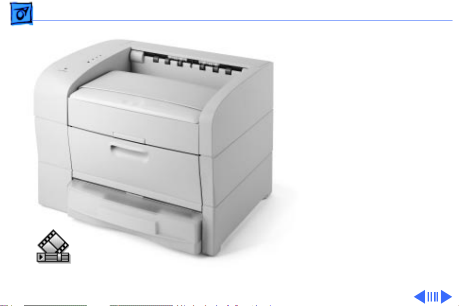
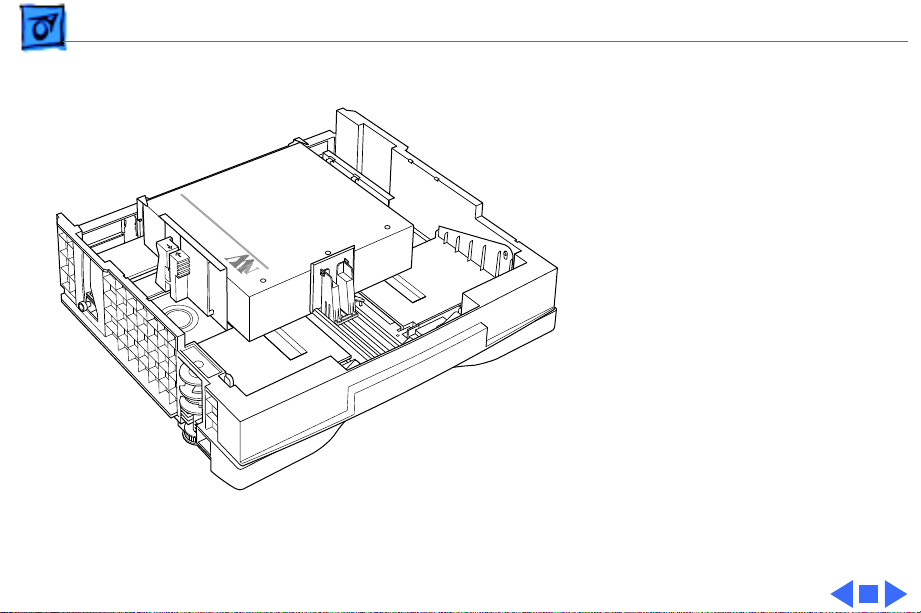
360 Degree View
LaserWriter 8500 Basic Configuration
Page 4

Overview General - 2
General
The LaserWriter 8500 is a 600 dpi, 20 ppm monochrome
laser printer that is capable of printing onto paper up to 13
x 20 inches in size. In its basic configuration, the printer
has a capacity of 650 sheets, the standard cassette holding
500 sheets (as compared to the 250 typical in earlier
printers), the multipurpose tray holding 150.
There are several options available for the printer,
including a duplexer unit (for two-sided printing), a 500-
LaserWriter 8500 with
Duplexer and Sheet Feeder
360 Degree View
sheet feeder, and an envelope cassette.
Page 5
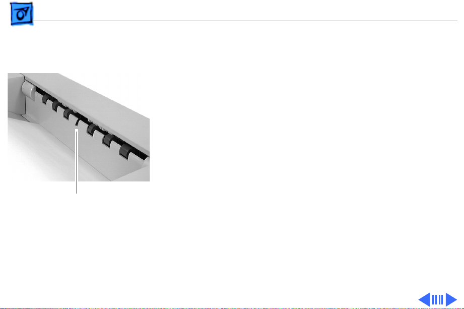
Overview Duplexer - 3
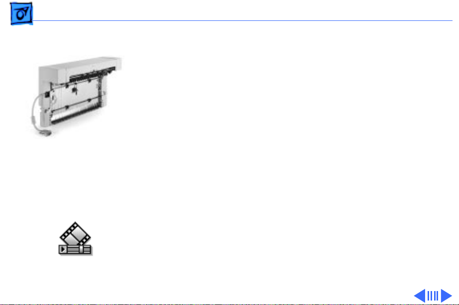
Duplexer
The duplexer is an inverted L-shaped feeder that mounts
Duplexer
Paper Path
Through Duplexer
onto the upper rear of the printer. Once installed,
(even simplex) diverts into and exits from the duplexer.
This is unlike the LaserWriter 12/640 PS, which employs
a solenoid-actuated diverter controlled through software.
The operative element in the LaserWriter 8500 is the
exchange chute, located in the fuser assembly. The exchange
chute is actuated (i.e. locked in place) during installation of
the duplexer.
After the first pass of a duplex page, the paper partially
exits the duplexer delivery rollers. The rollers then
reverse and the paper feeds back down through the duplexer
and into the printer engine, in preparation for imaging of
the second side. The paper then exits through the duplexer
into the delivery tray.
all
paper
Page 6

Overview Paper Path - 4
The duplexer derives its power from the printer engine but
has its own motor to generate mechanical drive.
Offset Function
The duplexer has a job separation feature that allows print
jobs to be stacked offset (i.e. staggered left-to-right) in the
delivery tray. Job separation is set in the Apple Printer
Utility.
Note
: Due to cost considerations, the offset function has been
incorporated into the duplexer instead of the printer engine.
Offsetting and duplex printing are otherwise unrelated to one
another.
The offset motor in the duplexer generates the mechanical
drive for offsetting paper.
Page 7

Overview Sheet Feeder - 5
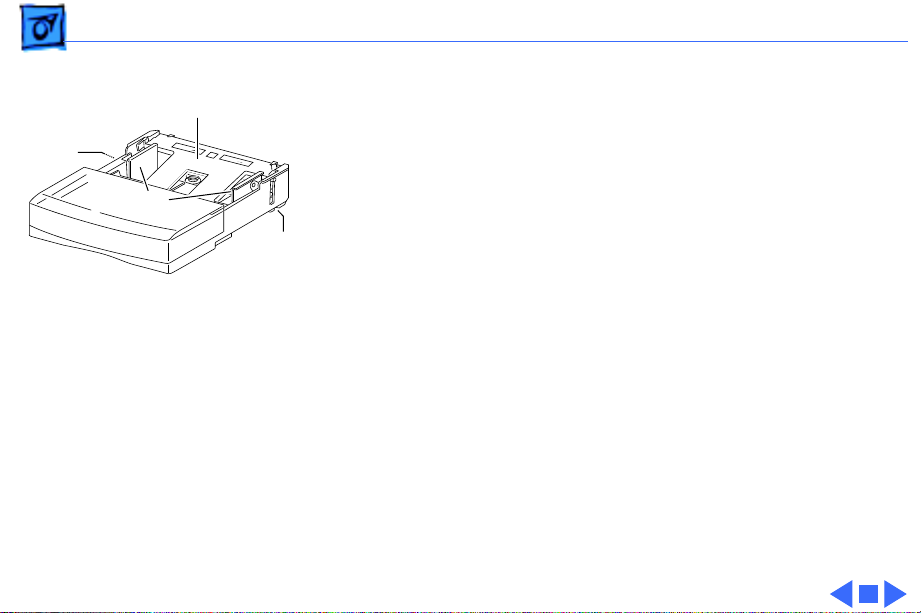
Sheet Feeder
As with the LaserWriter 16/600 PS and LaserWriter 12/
640 PS designs, the sheet feeder fits squarely beneath the
printer to form a dual front-loading cassette arrangement.
Unlike those models, however, you can stack two feeders
Sheet Feeder
beneath the printer, for a total auxiliary capacity of 1000
sheets. Also unlike those models, the sheet feeder and the
engine use identical cassettes in the LaserWriter 8500.
The sheet feeder derives its power and mechanical drive
from the printer engine.
Page 8
Overview Form Factor - 6
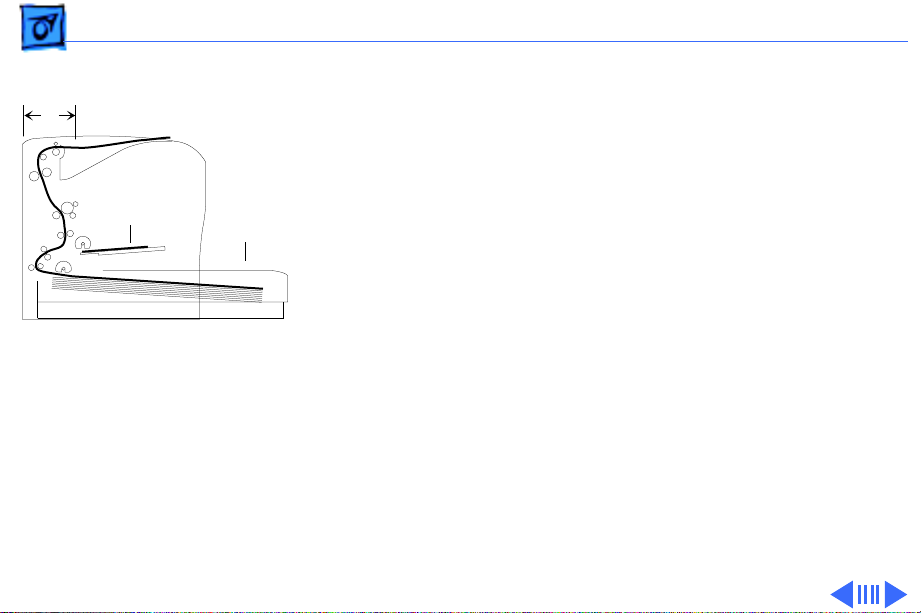
Form Factor
C
To achieve a reasonably compact form factor, the tail end of
the cassette has been designed to extend out from the engine
footprint (A). Consequently, the pickup rollers feed from
D
A
B
Printer Cross-Section
Note: Diagram shows printer
with long cassette and oversize (11 x 17 inch or A3)
paper installed.
the insertion end of the cassette (B), similar to the LaserWriter II. This arrangement influences the architecture of
the printer in the following ways.
1 Because pickup occurs deep within the printer, all
mechanical drive elements are arranged vertically along
the rear (C), resulting in a simple C-shaped paper path.
This vertical arrangement yields a compact, lowmaintenance gear train, consisting at its essence of one
gear assembly driven by one central motor.
2 You can stack letter-sized paper on the multipurpose
tray and shut the cover (D), thus hiding that paper from
view inside a multipurpose “compartment.”
Page 9
Overview Form Factor - 7
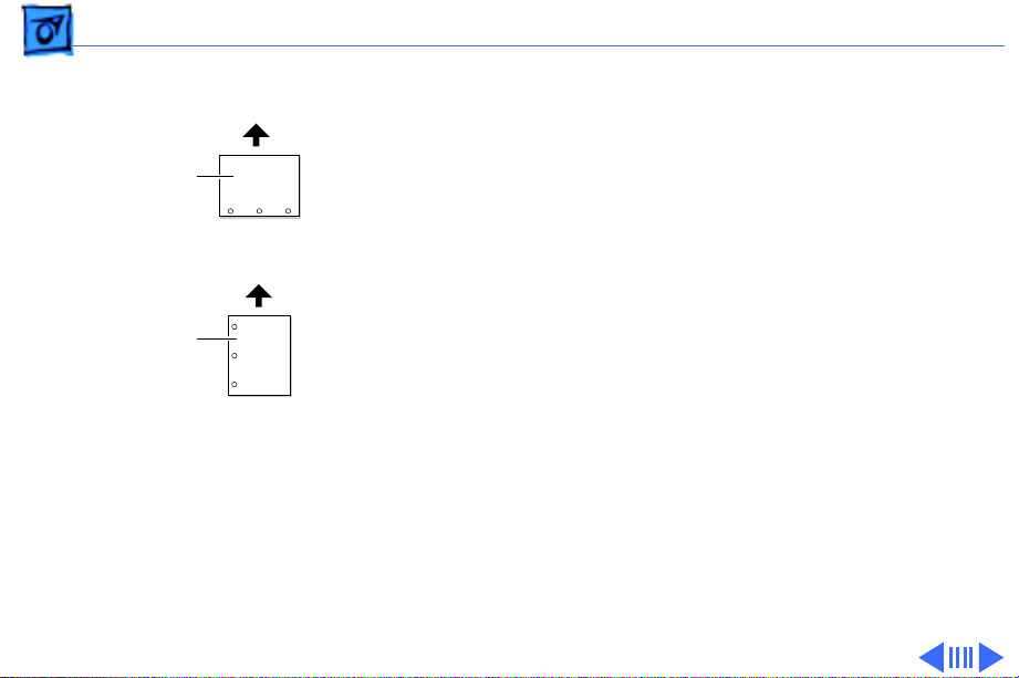
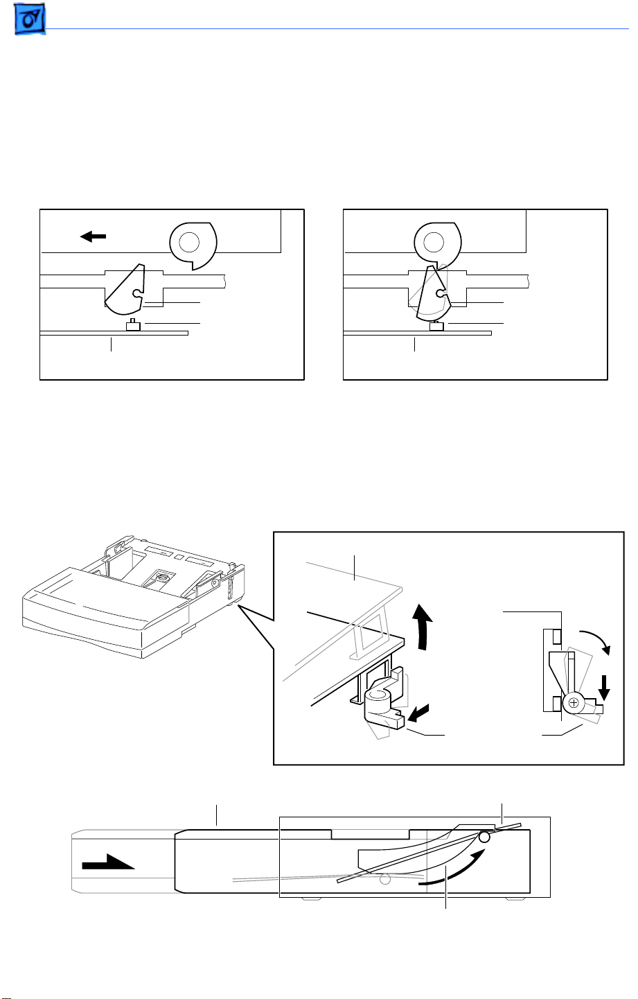
3 The design of the cassette bottom plate (A) is new.
A
C
Below the plate, three springs provide upward pressure
that forces the paper against the pickup rollers. (Only
two of the springs are activated when the width guides
B
C
(B) are set for narrower paper). In most printers, the
bottom plate receives constant uniform pressure from
the springs. As you insert the cassette, the paper snugly
and passively presses against the pickup rollers.
With this printer, however, the bottom plate must stay
down during insertion to avoid snagging. The springs are
released, and the bottom plate elevated against the pickup
rollers, only when the cassette is fully inserted.
This spring release is actuated by a latch on each side of
the cassette near the leading edge (C). See “Cassette” in
the Basics chapter for more information.
Page 10
Overview Paper Orientation - 8
Long-Edge Feed
(LEF)
Short-Edge Feed
(SEF)
Feed
Feed
Paper Orientation
The paper path is wide enough to print letter or A4 sized
paper in long-edge feed (LEF) mode. LEF mode is recommended as it achieves the fastest 20 ppm throughput and
optimizes duplex printing.
Note
: The cassette automatically senses paper orientation.
The multipurpose tray does not. Printing in short-edge feed
(SEF) mode from the multipurpose tray may produce
undesirable results.
Paper orientation and how best to load paper can be
confusing, especially when talking with customers over the
phone. It is further complicated when printing duplex jobs.
Keep in mind the following tips:
• Use the LEF and SEF terms when talking about how paper
is loaded. These are the terms found in the user manual.
Page 11
Overview Paper Orientation - 9
• The terms “portrait”
and “landscape” are best
used only when talking
about how a printed page
is to be formatted.
Remember that LEF
mode, for example, can
result in either a
landscape or a portrait
formatted page.
• Load letterhead face-up.
• As you stand facing the
printer: the top of the
page is on the left for LEF
portrait, and on the near
side for LEF landscape.
LEF Paper Orientation
Page 12
Overview Service Test Page - 10
Service Test Page
A service test page, sometimes called an engine test page, is a
page whose description resides in firmware on the DC
controller board. Successful printing of a service test page
confirms the operation of the print engine. Of equal importance, if a print quality problem appearing on a normal page
Service Test Page
also appears on the service test page, the I/O controller
board is proven good and should not be swapped.
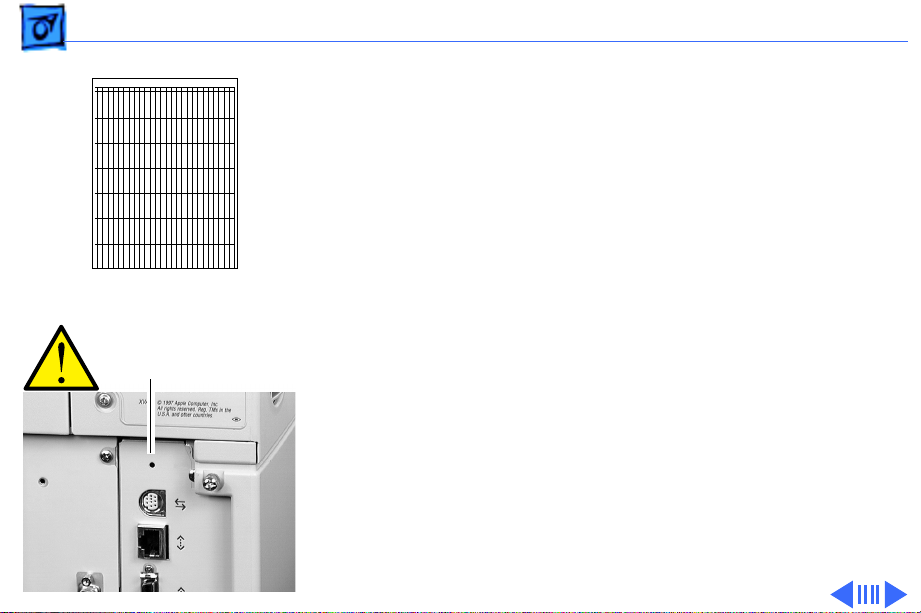
Test Page Button
There are two ways to print a service test page on the LaserWriter 8500.
1 If the I/O board is installed, use a paper clip to press the
test page button. This button is accessible through a
small unmarked hole at the top of the I/O bracket.
Note
: Use this button liberally, both in person and when
troubleshooting with customers on the phone. It is your
Page 13
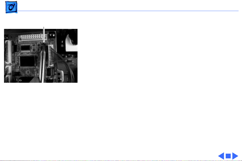
Overview Service Test Page - 11
Test Page Jumper
first line of defense in isolating faults between the I/O
board and printer engine.
2 If the I/O board and shield have been removed from the
printer, you can print a service test page by jumpering
the two pins of connector P23 on the DC controller
board.
Page 14

Overview RAM Memory - 12
RAM Memory
The LaserWriter comes with 16 megabytes (MB) of RAM soldered onto the I/O
controller board. There is one SIMM slot available for installing additional RAM. The
following table lists the memory requirements and supported paper sizes for duplex
printing and PhotoGrade.
Memory Duplex Printing PhotoGrade Use both features at once?
16 MB Letter, A4, B4, legal Letter, A4, B5 No
20 MB Letter, A3, A4, B4, Up to ledger and A3 Yes; up to letter and A4
legal, ledger
24 MB Letter, A3, A4, B4, Up to Japan Standard Yes; up to legal
legal, ledger and Japan Larger
32 MB Letter, A3, A4, B4, All supported paper Yes; up to B4
legal, ledger sizes
48 MB Letter, A3, A4, B4, All supported paper Yes; all supported paper
legal, ledger sizes sizes
Page 15

Overview SIMM Sizes and Speeds - 13
SIMM Sizes and Speeds
Size Configuration Speed Connector type
4 MB SIMM 1 M X 32 bit (one 4 MB bank) 70 ns or less 72-pin
8 MB SIMM 2 M X 32 bit (two 4 MB banks) 70 ns or less 72-pin
16 MB SIMM* 4 M X 32 bit (one 16 MB bank) 70 ns or less 72-pin
32 MB SIMM* 8 M X 32 bit (two 16 MB banks) 70 ns or less 72-pin
* Must have a 2 KB row (11 bit x 11 bit) refresh rate. 16 MB SIMMs with a 4 KB row (12 bit x
10 bit) refresh rate are not compatible with the printer.
Page 16
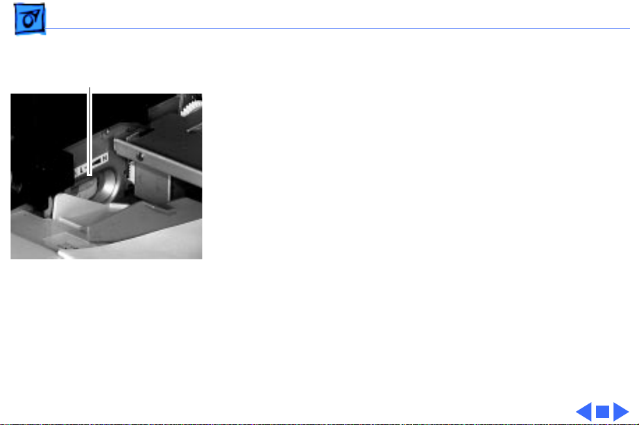
Overview Miscellaneous - 14
Miscellaneous
Full-Stack Sensor
When the delivery tray is full of paper, the printer stops
accepting print jobs and the controller reports an error
message to the host computer. Sensing of delivery tray
capacity is done through the full-stack sensor located just
above the delivery rollers.
With a duplexer installed, the duplexer full-stack sensor
Actuator for
Full-Stack Sensor
assumes this function. The parts used in the duplexer
actuator and the printer actuator are
not
interchangeable.
Other Sensors and Interlocks
All other sensors and interlocks are similar to previous
printers and will be familiar to the experienced technician.
See “Sensing System Locator” in the Basics chapter for a
Page 17
Overview Miscellaneous - 15
comprehensive diagram.
There is also a mechanical interlock that disengages the
fuser assembly drive train when the top cover is open (to
facilitate removal of paper jams). See “Top Housing and
Xerographics” in the Basics chapter.
Point-of-Sale (POS) Button
The Ready LED is also a button that actuates a microswitch on
the status panel board. If you hold this LED during printer
startup, the printer will enter the special POS state (or exit
from POS if POS is currently enabled). You can also make
these settings through the Printer Utility.
During POS state, the ready LED flashes two shades of green
Demonstration Page
instead of the normal steady green. When you press the
ready LED thereafter, a special demonstration page will
print. While in POS state, the energy saving feature is
Page 18

Overview Miscellaneous - 16
disabled, but in all other ways, the printer is networkaware and will perform just as it does in ready state.
Voltage-Specific Parts
Four parts in the printer are available in both 110V and
220V versions:
• Power supply
• Fuser assembly
• Transport chute assembly
• DC controller board
Note
: The DC controller board, though universal in
previous printers, is not in the LaserWriter 8500.
The second version of this board satisfies European
Economic Community requirements and has made possible
some localization of controller board firmware (default
paper size for the multipurpose tray, for example).
Page 19
Overview Miscellaneous - 17
Density Adjustment
Density Adjustment Dial
On the left side of the multipurpose tray compartment, there
is a density adjustment dial. This dial changes the DC
component of the development bias voltage supplied by the
high-voltage power supply. The dial adjusts the threshold
voltage, in effect changing the background density across the
entire imageable page.
A second method of density adjustment is through the Apple
Printer Utility, which adjusts the laser power output. In
effect, this adjusts the density of the printed pixels.
Page 20

K
Service Source
Basics
LaserWriter 8500
Page 21
Basics Function of Main Components - 1
Function of Main Components
This topic describes the function of the following components of the LaserWriter 8500.
•Cassette
•Cassette Feed Components
•Manual Feed Components
•Paper Transportation
•Fusing and Paper Exit
•Frame and Drive
•Top Cover and Xerographics
•Electrical
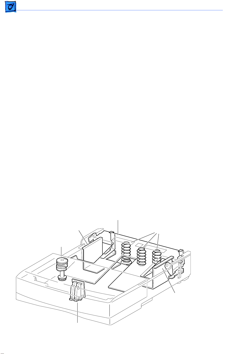
Cassette
Paper Width Guides
The paper width guides are adjusted left-to-right to accommodate different paper widths.
They contact the left and right sides of the paper stack and hold the paper stack in place in
the crosswise direction.
The left and right snubbers (paper separating claws) at the leading edge of paper allow
only one sheet of paper to be fed from the cassette into the printer. The snubbers move
together with the paper width guides.
Pressure Plate Springs
Two pressure springs act against the bottom plate when paper width is less than 8.5
inches (216 mm). When the paper width is greater, additional forced is deemed necessary
and a third pressure spring is released against the bottom plate. The mechanism that
releases or contains the third spring is controlled by the paper width guides.
Bottom Plate Assembly
Left Width Guide
Size Cams
Pressure Plate Springs
Paper End Guide
Right Width Guide
Page 22
Basics Function of Main Components - 2
Paper End Guide
The paper end guide can be adjusted front-to-rear to accommodate different paper
lengths. It is in contact with the trailing edge of the paper stack.
When the paper end guide is adjusted, the size cams on the left side of the cassette rotate
into a unique pattern of projections and gaps. When you insert the cassette, the position of
the cams align with actuators that are housed in the printer’s left cassette guide assembly.
The actuators correspond to four microswitches on the cassette feed board.
Cassette
Cassette Feed Board
Size
Cam
Size Actuator
Size Switch
Size
Cam
Size Actuator
Size Switch
Cassette Feed Board
Cassette Latches
On each side near the leading edge of the cassette are two cassette latches. When the
cassette is outside the printer, these latches hold the bottom plate down against the force
of the pressure plate springs. As the cassette is inserted, the latches release and the
bottom plate elevates.
Bottom Plate Assembly
Cassette
Right Cassette
Latch
Bottom Plate Assembly
Cassette Guide
(in Printer)
Page 23
Basics Function of Main Components - 3
Cassette Feed Components
Turn Clutch
Cassette Feed Solenoid
and Feed Gear
Cassette Feeder Board
The feeder board has the paper size microswitches (see previous topic) and serves as a
relay board for the signals between the cassette feed and the DC controller board.
Cassette Paper-Present Sensor and Actuator
This sensor detects the presence of paper in the cassette.
Cassette Feeder Board
Cassette Paper-Present
Sensor and Actuator
Cassette Feed Solenoid and Feed Gear
When the feed solenoid is actuated, the feed gear is releases and turns to engage with the
feed idler gear. The feed gear then begins to rotate, causing the pickup rollers to rotate.
After one revolution, the feed gear disengages from the feed idler gear and is latched by the
pawl of the feed solenoid.
Turn Clutch
The turn clutch is an electromagnetic clutch that switches on and off the drive power to
the lower and upper feed rollers.
Lower and Upper Feed Rollers
These rollers have an integral metal shaft/rubber roller design. Drive to the rollers is
controlled by the turn clutch so that the rollers start feeding from the pickup area and
stop feeding at the registration sensor.
When the engine receives a /PRFD signal from the controller, the engine stops feeding at
the registration sensor and resumes when it receives a subsequent /START signal. If the /
START signal is received before the paper reaches the registration position, the printer
will feed the paper continuously without stopping the rotation of the feed rollers.
Pickup Rollers
Rotate and feeds one sheet of paper each time the cassette feed solenoid is actuated.
Page 24
Basics Function of Main Components - 4
Manual Feed Components
Manual Feed
Sensor Assembly
Toner Sensor
Manual Feed Guide Tray
Manual Feed
Paper-Present Sensor
Manual Feed Guide Tray
The manual feed guide tray is the pressure plate and width guide for manual feed paper.
During standby the tray is held down by the pickup roller assembly cams. When the paper
is about to feed, the cams move off the tray due to the rotation of the pickup roller
assembly. The manual feed guide tray is therefore pressed up by the two pressure springs
and the paper is pressed against the pickup roller.
Manual Feed Paper-Present Sensor
Part of the manual feed sensor assembly, this sensor detects the presence of paper in the
manual feed compartment.
Toner Sensor
Also part of the manual feed sensor assembly, this sensor detects low toner by responding
to the magnetism of the toner in the cartridge.
Page 25
Basics Function of Main Components - 5
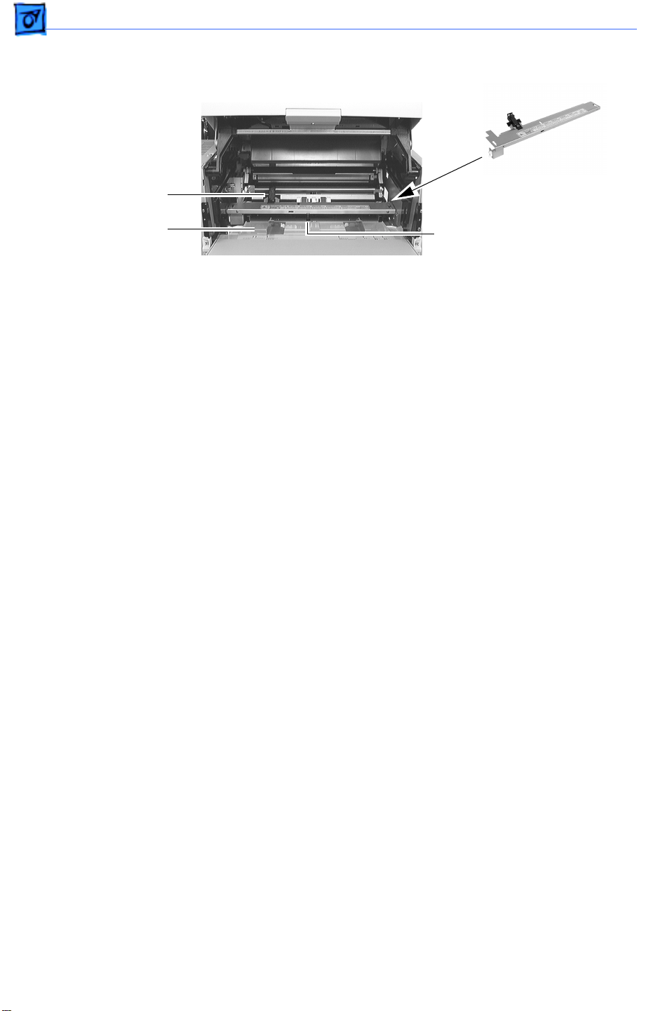
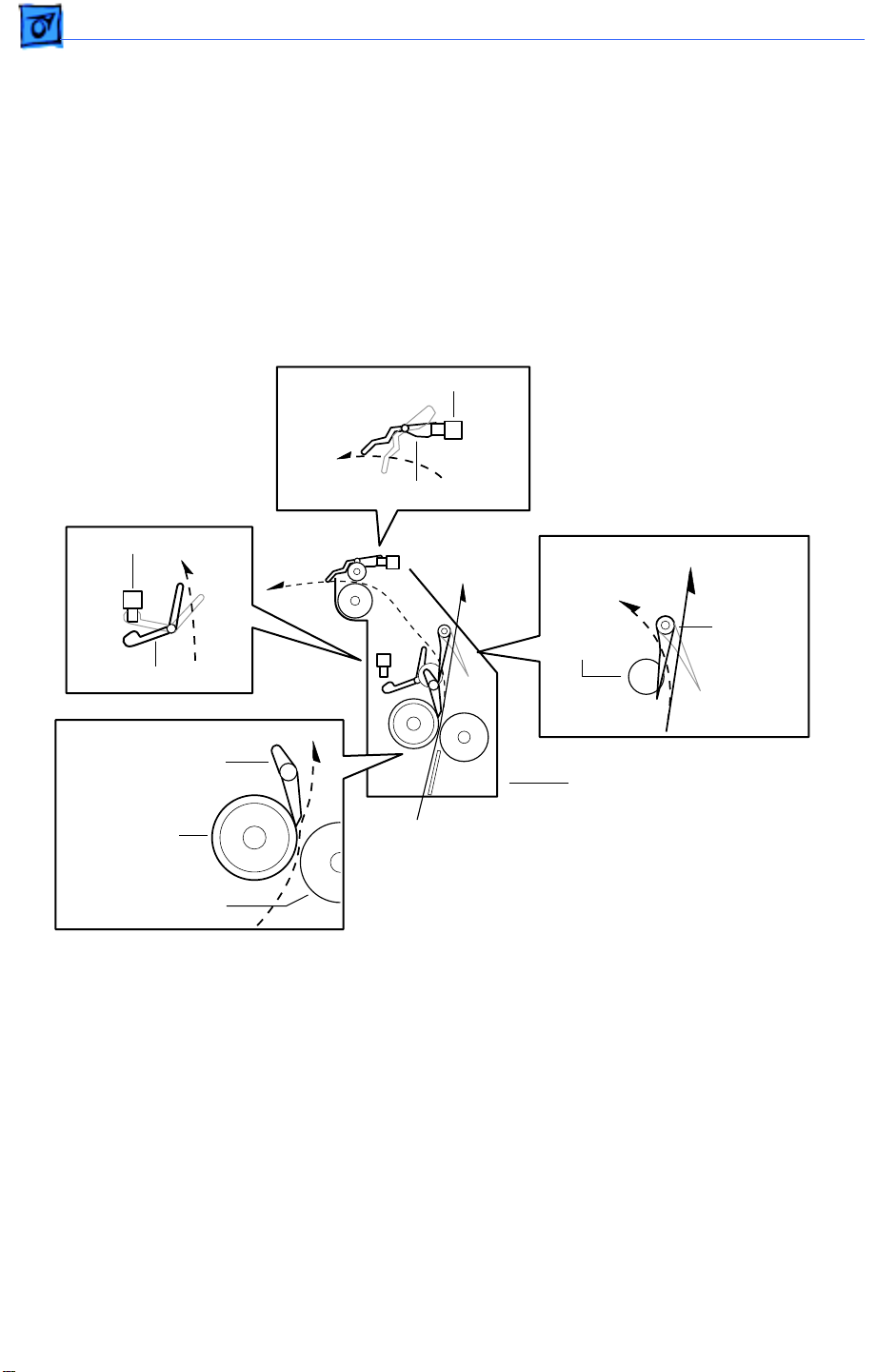
Paper Transportation
Transfer Roller Assembly
Transport Chute Assembly
Transfer Roller Assembly
The transfer roller is in contact with the drum in the toner cartridge. The roller is driven
by the drum gear so that the roller surface moves at the same speed as the drum surface.
The transfer roller applies a positive charge to the back side of the paper when the paper
travels between the roller and the drum. The negatively charged toner image transfers
from the drum surface to the front side of the paper because it is attracted by the positive
charge on the back side of the paper.
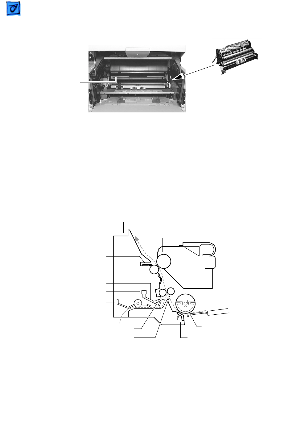
Transport Chute Assembly
Transport Chute Assembly
Photosensitive Drum
Detack Saw
Transfer Roller
Toner
Cartridge
Registration Actuator
Registration Sensor
Rear Chute Assembly
Rubber Registration Roller
Metal Registration Roller
Pickup Roller
Separation Pad
Included in the transport chute assembly are the following components.
Pickup roller assembly
: Consists of two pickup rollers, three core rollers, pickup cams,
and the shaft. It rotates one turn each time the manual feed pickup solenoid is actuated, and
feeds one sheet of paper from the manual feed compartment.
Pickup solenoid and pickup gear
: When the pickup solenoid is actuated, the pickup gear is
released and turned by the pulling force of the pickup spring to engage with the opposite
gear in the main gear assembly. The pickup gear then begins to rotate, causing the pickup
roller assembly to rotate. After one revolution, the pickup gear disengages from the
opposite gear because of its sector-shaped cutout and is latched by the pawl of the feed
Page 26

Basics Function of Main Components - 6
solenoid.
Separation pad assembly
: Prevents extra sheets of paper from being fed by the friction
between the paper and the rubber of the separation pad.
Rear chute assembly
: Guides the paper fed from the cassette between the metal and rubber
registration rollers.
Metal registration roller and rubber registration roller
: The rotation of these rollers is
controlled by means of the registration clutch assembly so as to register the paper with
the image on the drum.
Registration sensor
: Detects the arrival and departure of the paper at the registration
position.
T ransfer r oller bearing
: Applies the transfer voltage from the high-voltage power supply to
the transfer roller assembly.
Detack saw
: Imparts a negative charge to the back side of the paper, partially neutralizing
the positive charges, so that the paper can peel off the drum.
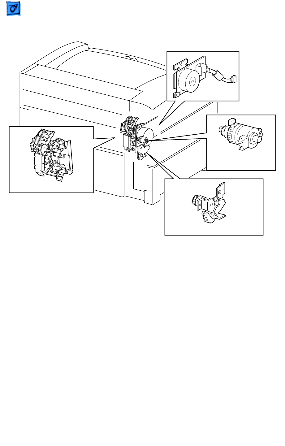
Duplexer
The duplexer derives its mechanical drive from the duplex motor. The offset motor
generates the lateral drive for job separation (left-to-right staggering of paper in the
delivery tray).
Offset Gear
Gear B
Gear A
Drive Belt
Duplex Motor
Duplexer
Gear B
Gear C
Gear D
Pulley Gear
Pulley Gear
Page 27
Basics Function of Main Components - 7
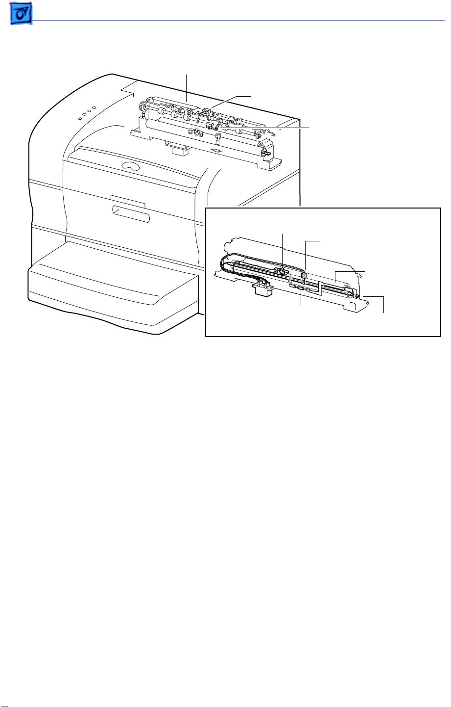
Fusing and Paper Exit
Fuser Assembly
Full Stack Sensor and Actuator
Exit Sensor and Actuator
Thermostat
Temperature Sensor
Assembly
Pressure Roller
Thermal Fuse
The fuser assembly houses all components of fusing (the permanent fixing of toner to
paper by means of heat and pressure), as well as components for paper delivery.
Fuser Bulb
(Inside Heat Roller)
Heat Roller
The heat roller is a hollow metal tube that applies heat to the paper passing between it and
the pressure roller. The heat is generated by the fuser bulb inside the heat roller. This
heat melts the toner on the paper.
Pressure Roller
The pressure roller is a solid, sponge rubber-coated metal shaft that presses the paper
against the heat roller. The pressure helps bond the toner to the paper.
Heater Assembly
The heater assembly consists of the fuser bulb and the wiring and connectors attached to
the ends of the bulb.
Temperature Sensor Assembly
The temperature sensor assembly is a thermistor whose resistance varies sharply with a
change in temperature. This sensor is held in contact with the heat roller surface and
monitors the temperature thereof. The signal from this sensor is used to maintain the
temperature of the heat roller surface within the specified range by switching the power
to the heater bulb on and off. The signal is also used for the first-stage overheat
protection.
Thermostat
The thermostat is part of the heater bulb circuit ad functions as the second-stage overheat
Page 28
Basics Function of Main Components - 8
protection. If the temperature sensor assembly fails to prevent a fuser overheat, the
thermostat opens and power is cut to the heater bulb.
Thermal Fuse
Also a part of the heater bulb circuit, the thermal fuse functions as the third-stage
overheat protection. If both the first and second stages fail to prevent a fuser overheat, the
thermal fuse opens and power is cut to the heater bulb.
Heat Roller Diode
There is a negative charge that builds up on the heater bulb. This charge can disturb the
toner image on the paper during fusing. The heat roller diode grounds this charge.
Full Stack Sensor
Full Stack Actuator
Exit Sensor
Exit
Chute
Roller
Exit Actuator
Heat Roller Finger
Fuser Assembly
Heat Roller
Pressure Roller
To Duplexer
Exchange
Chute
Heat Roller Fingers
These fingers work in conjunction the non-stick coating of the heat roller to peel the
leading edge of the paper from the roller.
Exit Sensor
The exit sensor detects the arrival and departure of the paper on the delivery side of the
heat roller.
Full Stack Sensor
The full stack sensor detects when the delivery tray is full of paper.
Exchange Chute
The installation of an optional duplexer locks the exchange chute into a position so that all
paper is directed up into the duplexer.
Page 29
Basics Function of Main Components - 9
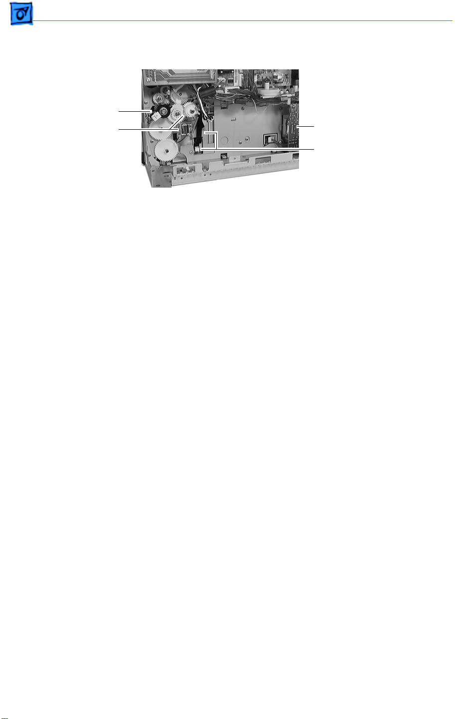
Frame and Drive
Main Motor
Registration Clutch
Assembly
Main Gear Assembly
Paper-Handling Gear Assembly
Main Motor
Generates all the drive power for the printer and optional sheet feeder.
Main Gear Assembly
Distributes drive power from the main motor to the fuser assembly, toner cartridge,
paper handling gear assembly, registration clutch assembly, and pickup gear.
Paper Handling Gear Assembly
Transfers the drive power from the main gear assembly to the feed idler gear and to a
second gear within the main gear assembly.
Registration Clutch Assembly
An electromagnetic clutch that switches the drive power on and off to the two registration
rollers at a specified time after the registration sensor has detected the arrival of the
paper. This clutch actuates momentarily after the paper arrives at the registration
rollers to allow the feed rollers to remove any skew induced during paper feed.
Page 30
Basics Function of Main Components - 10
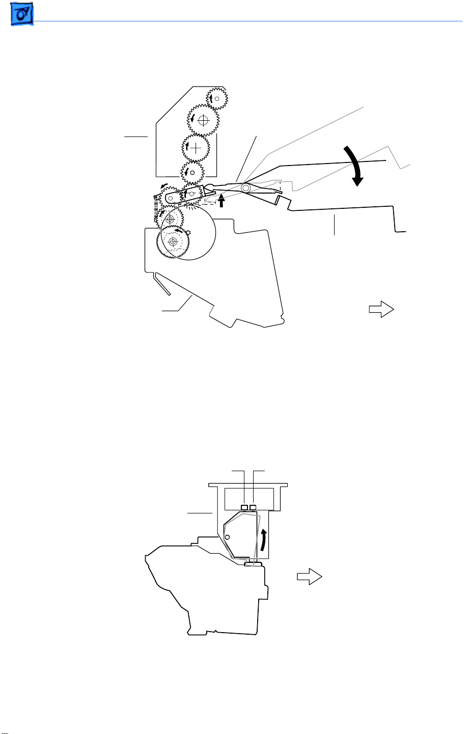
Top Housing and Xerographics
Guide Arm and Fuser Guide Lever
Fuser Guide
Fuser Assembly
Lever
Top Cover
Main Gear Assembly
Front
When the top cover opens, the fuser guide lever presses down on the floating idler gear at
the top of the main gear assembly, thus disengaging the fuser assembly from the gear
train. This makes removal of paper jams from the fuser much easier. When the top cover
is closed, the floating idler gear springs upward to mate the fuser gearing to the main gear
train.
Cartridge Sensor Assembly
Cartridge-Present Switch LD Switch
Cartridge Sensor Assembly
Toner
Cartridge
Front
The cartridge sensor assembly houses the two switches below.
Cartridge-present switch
: The signal from this switch stops printer operation when the
toner cartridge is absent or the top cover is open.
Page 31

Basics Function of Main Components - 11
Laser-diode (LD) switch
: This switch opens the laser diode circuit when the toner cartridge
is absent or the top cover is open. The LD switch protects users against exposure to the
laser light.
Toner Cartridge
The toner cartridge consists of five major components.
Photosensitive drum
: An aluminum cylinder with a surface coating of photoconductive
material. The photoconductive coating holds an electrical charge, and allows the charge to
flow through the thickness when exposed to light.
Bias charge roller (BCR)
: Places a uniform electrical charge on the drum surface, erasing
any charging patterns remaining from the previous cycle.
Magnetic roller
: Holds a thin layer of toner on its surface and transports it to the gap
between the drum and the magnet roller. Toner is supplied to the magnetic roller by two
agitators inside the toner compartment.
Charging and metering (CM) blade
: Spreads a thin layer of toner on the magnetic roll and
gives toner a negative charge.
Cleaning blade
: Scrapes the toner off the drum surface that is remaining after the
transfer stage.
Laser/Scanner Assembly
Laser Diode Assembly
Front
Scanner Mirror
M
L
MM
L = Lens
L
Laser/Scanner Assembly
SOS Board
Photosensitive Drum
M
M = Mirror
SOS = Start of Scan
The laser/scanner assembly scans a light beam onto the surface of the photosensitive
drum. This assembly consists of three major components: the laser diode, the scanning
mirror, and the start-of-scan (SOS) board.
Page 32

Basics Function of Main Components - 12
Electrical
Fuser Access Cover
Actuator
Fuser Cover
Interlock Switch
Actuator
Top Cover
Top Cover
Interlock Switch
Top Cover Interlock Switch
The top cover interlock switch is a safety switch that interrupts the supply of 24 VDC
from the power supply to the DC controller board whenever the top cover is open. This
switch also causes the power supply to interrupt AC line voltage to the fuser assembly.
The switch is located inside the left cartridge guide and is actuated by the nylon tip at the
end of the laser/scanner actuator rod.
Fuser Cover Interlock Switch
A safety switch that stops operation of the main motor, the laser/scanner assembly, and
the fuser whenever the fuser access cover is open. The switch is located on the right side
of the fuser access cover opening.
Fan
High-Voltage Power Supply
DC Controller Board
Print Density Adjustment Knob
(Service Access Side)
Power Supply
Fan
The fan exhausts the air inside the printer to prevent an excessive heat caused by the
fuser assembly. There is one fan in the LaserWriter 8500.
Power Supply
The power supply produces regulated low DC voltages from AC power. The power supply
also switches on and off the AC power to the fuser heater bulb. The main power switch is
hard-wired to the power supply.
High-Voltage Power Supply
The high-voltage power supply produces high voltage power for the charge and magnetic
roller in the toner cartridge, the transfer roller, and the detack saw.
Page 33

Basics Function of Main Components - 13
DC Controller Board
The DC controller board controls all printer operations. It has the following six major
functions.
1. Communicates with the I/O board.
2. Communicates with the optional duplexer.
3. Receives information from the printer sensors and switches.
4. Controls the laser/scanner, fuser, and main motor.
5. Controls the printing process.
6. Distributes DC power from the power supply to other printer components.
Print Density Adjustment Knob
This knob adjusts the print density by changing the DC component of the developing bias
voltage supplied by the high-voltage power supply. Turning this knob clockwise increases
the print density. Turning this knob counterclockwise decreases the print density.
Print Density Adjustment Knob
(User Accessible Side)
Page 34

Basics Sensing System Locator (Printer Engine) - 14
Sensing System Locator (Printer Engine)
Cartridge Sensing and Laser/Scanner Interlock
Sensor: Cartridge Sensor Assembly (P/N 922-2811)
Actuator: As the top cover closes, a tab on the toner cartridge
presses an actuator in the cartridge sensor assembly.
A
(Fuser Assembly)
Full Stack Sensing (A)
B
Sensor: Part of Fuser Assembly
Actuator: P/N 076-0653
Exit Sensing (B)
Sensor/Actuator: Part of Fuser
C
D
Assembly
(Transport Chute Assembly)
Registration Sensing (C)
Sensor/Actuator: P/N 076-0652
E
(Manual Feed Sensor Assembly)
Toner Sensing (D)
Toner Sensor Assembly (P/N 922-2799)
Manual Feed Paper-Present Sensing (E)
Sensor: P/N 922-2774
Acutator: P/N 922-2798
Fuser Cover Interlock
Actuator: As the fuser access cover
(P/N 922-2757) closes, a tab on the
cover presses the switch.
Switch: P/N 922-2813
Top Cover Interlock
Actuator: As the top cover closes,
the nylon tip of the laser/scanner
actuator rod presses the switch.
Switch: P/N 922-2812
Paper Size Sensing
Actuators: As cassette is inserted,
size cams on cassette meet four
size actuators on left cassette
guide assembly (P/N 922-2773).
Switches: Size actuators press
microswitches on the cassette
feeder board (P/N 922-2770).
Cassette Paper-Present Sensing
Actuator: P/N 922-2776
Sensor: P/N 922-2774
Page 35

Basics Sensing System Locator (Duplexer) - 15
Sensing System Locator (Duplexer)
Full Stack Sensor
Full Stack Actuator (P/N 922-3038)
Duplex Paper-Pass Sensor
(P/N 922-3037)
Duplexer Full
Stack Actuator
Duplexer Full
Stack Sensor
Upper Cover Interlock Switch
Duplexer Upper Cover
Duplexer Lower Cover
Paper-Pass
Sensor
Lower Cover Interlock Switch
Page 36

Basics Wiring Diagram - 16
Wiring Diagram
Full Stack
Sensor
Offset
Motor
P/J
192
P/J
196
P183
Fuser Cover
Interlock Switch
Exit
Sensor
Full
Stack
Sensor
Temp. Sensor
Heater Bulb
Thermostat
Thermal Fuse
Fuser Assembly
Paper-Pass Sensor
Duplex Motor
Interlock
Switches
P/J
P/J
193
198 P/J
197
195
P/J187P/J184P/J186
Duplexer Board
Duplexer
Main Motor
Cartridge-Present Sensor
Manual Feed
Sensor Assembly
Toner Sensor
Manual Feed Paper-
Present Sensor
Registration Sensor
Registration Clutch
Manual Feed Solenoid
P182
P/J
P/J
190
180
Power Inlet
Duplex Interface Board
P/J
942
P/J
142
Power Switch
P/J
Fan
Toner
Cartridge
DB CR DTS TR
HVPS
M
P/J221
P/J
134
P/J937
P/J
132
P/J135
P/J
122
P/J
124
Laser/Scanner
LD SOS MOT
P/J
112
P/J
P/J
15
151
P/J
16
P/J
P/J
171
17
P/J
22
P/J222
P/J922
P/J137
P/J
13
P/J131
P/J935
P/J
18
P/J
14
P/J11
P/J127 P/J121
Power Supply
P/J
113
P/J12
DC
Controller
Board
P/J21
P/J
114
P/J
20
P/J
23
P/J
19
P/J
31
Interlock Switch
Layout of sheet feeder is identical
to cassette feeder board.
Sheet Feeder
P207
P202
Turn Clutch
P/J206P/J205
Cassette
Feeder
Board
P201
Actual
Board
Layout
Test Print
I/O Board
Top Cover
P/J
123
P/J
126
P/J
203
P12P17P14P18
P21 P11 P20
P/J412
Cassette Feed
Paper-Present
Sensor
P/J904
P/J204
Cassette Feed
Solenoid
P31
P23
DC
Controller
Board
P16
P/J
P/J
411
421
P13 P22 P19 P15
Status
Panel
Page 37

K
Service Source
Specifications
LaserWriter 8500
Page 38

Specifications Engine - 1
Engine
Marking engine
Laser
Fuji Xerox P880 laser-xerographic
Type: Semiconductor laser diode
Wavelength: 780 nanometers (nm)
Output power: 5 milliwatts (mW) maximum
Page 39

Specifications Controller - 2
Controller
Microprocessor
ROM
RAM
I/O processor
EEPROM
AMD Am29040 30/60-MHz RISC microprocessor
8 megabytes (MB) of ROM (including 136 fonts)
16 MB of RAM (expandable to 48 MB). See “RAM Memory” in the
Overview chapter for more information.
80C186 I/O processor
8 kilobytes (KB) parameter EEPROM
Page 40

Specifications Ports - 3
Ports
General
LocalTalk port
Parallel port
AAUI Ethernet port with three protocols:
EtherTalk
Novell NetWare IPX (PSERVER or RPRINTER)
TCP/IP (lpd)
External Ethernet transceivers available for
thin coaxial (10BASE-2)
thick coaxial (10BASE-5)
Ethernet twisted-pair cable (10BASE-T) can connect directly to
a hub
Two-position communication switch
All ports and protocols simultaneously active (but only one
Ethernet connector)
Page 41

Specifications Imaging - 4
Imaging
Resolution
Grayscale imaging
PostScript
600 dots per inch (dpi) resolution
600 dpi FinePrint (edge enhancement for text and line art)
Enhanced 600 dpi grayscale imaging:
Standard
85 lines/inch dithered halftone, 101 gray levels
106 lines/inch dithered halftone, 129 gray levels
141 lines/inch dithered halftone, 73 gray levels
PhotoGrade (additional RAM may be required)
106 lines/inch halftone, 201 gray levels
141 lines/inch halftone, 257 gray levels
150 lines/inch halftone, 145 gray levels
PostScript Level 3
Page 42

Specifications Imaging - 5
Printer fonts
Speed
One hundred thirty-six PostScript fonts are provided with the
printer, including such fonts as Albertus, Antique Olive, Apple
Chancery, Arial, ITC Avant Garde ®, Bondoni, ITC Bookman ®,
Carta, Chicago, Clarendon, CooperBlack, Copperplate, Coronet,
Courier, Eurostile, Geneva, GillSans, Goudy, Helvetica, Helvetica
Black, Helvetica Compressed, Helvetica Narrow, Hoefler Text,
Joanna, LetterGothic, Lubalin Graph, Marigold, Monaco,
MonaLisa, New Century Schoolbook, New York, Optima, Oxford,
Palatino ®, StempelGaramond, Symbol, Tekton, Times, Univers,
Univers Condensed, WingDings, ITC Zapf Chancery ®, and ITC Zapf
Dingbats ®.
Note
: Actual speed depends on the images printed.
One-sided: 20 pages per minute maximum using long-edge feed
(LEF) U.S. letter or A4-size paper.
Duplex: 13 pages per minute maximum using long-edge feed U.S.
letter or A4-size paper.
Envelopes—9.7 envelopes per minute maximum.
Page 43

Specifications Life Expectancy - 6
Life Expectancy
Printer reliability (MTBF)
Toner cartridge life expectancy
Average number of impressions between failure is 180,000
pages. (In duplex mode, a single sheet is considered to be two
impressions.)
Life expectancy is up to 14,000 pages when printing text
documents with average page coverage (5% black). An example of
a 5% black page coverage is a page consisting of double-spaced
14-point Courier type. Printing images and other graphics may
shorten toner cartridge life expectancy.
Page 44

Specifications Printing Materials - 7
Printing Materials
Paper types
Paper sizes and capacity
16- to 28-pound laser-quality bond (60 to 105 g/m 2 ); up to
36-pound (135 g/m 2 ) stock when fed manually through the
multipurpose tray. Accepts most textured and colored stock.
Accepts medium-weight photocopier transparencies and labels.
Envelopes can be printed from the multipurpose tray or from the
optional envelope feeder.
The paper used should not scorch, melt, transfer material, or
release hazardous emissions when heated to 200° C (400° F) for
0.1 seconds.
The paper cassette holds 500 sheets of 20-pound (75 g/m 2 )
paper. The multipurpose tray can hold up to 150 sheets of
standard U.S. letter paper, and other paper sizes from postcard up
to U.S. legal. An optional 500-sheet feeder and cassette is
Page 45

Specifications Printing Materials - 8
available. An envelope feeder that can automatically feed up to 50
envelopes is also available.
Standard 500-sheet
cassette
Multipurpose tray
Paper Type Size
U.S. Letter (LEF) 8.5" x 11" (215.9 mm x 279.4 mm)
U.S. Letter Small (LEF) 8.5" x 11" (215.9 mm x 279.4 mm)
Statement (LEF) 8.48" x 5.48" (215.9 mm x 139.7 mm)
Executive (LEF) 10.5" x 7.25" (266.7 mm x 184.2 mm)
A4 (LEF) 8.27" x 11.69" (210 mm x 297 mm)
A4 Small (LEF) 8.27" x 11.69" (210 mm x 297 mm)
A5 (LEF) 5.84" x 8.26" (148 mm x 210 mm)
B5 (LEF) 7.17" x 10.12" (182 mm x 257 mm)
Paper Type Size
U.S. Letter (LEF) 8.5" x 11" (215.9 mm x 279.4 mm)
U.S. Letter Small (LEF) 8.5" x 11" (215.9 mm x 279.4 mm)
A4 (LEF) 8.27" x 11.69" (210 mm x 297 mm)
A4 Small (LEF) 8.27" x 11.69" (210 mm x 297 mm)
A5 (LEF) 5.84" x 8.26" (148 mm x 210 mm)
Executive (LEF) 10.5" x 7.25" (266.7 mm x 184.2 mm)
Page 46

Specifications Printing Materials - 9
B5 (LEF) 7.17" x 10.12" (182 mm x 257 mm)
Statement (LEF) 8.48" x 5.48" (215.9 mm x 139.7 mm)
U.S. Legal (SEF) 8.5" x 14" (215.9 mm x 355.6 mm)
U.S. Legal Small (SEF) 8.5" x 14" (215.9 mm x 355.6 mm)
Tabloid (SEF) 11" x 17" (279.4 mm x 431.8 mm)
A3 (SEF) 11.69" x 16.54" (297 mm x 420.2 mm)
Large (SEF) 13" x 18" (330 mm x 457.2 mm)
Large (SEF) 13" x 18.5" (330 mm x 470 mm)
Large (SEF) 13" x 20" (330 mm x 508 mm)
COM10 (SEF) 4.125" x 9.5" (104.8 mm x 241.3 mm)
Monarch (SEF) 3.875" x 7.5" (98.4 mm x 190.5 mm)
DL (SEF) 4.33" x 8.66" (110 mm x 220 mm)
C5 (SEF) 6.38" x 9.02" (162 mm x 229 mm)
Hagaki Postcard (SEF) 3.94" x 5.83" (100 mm x 148 mm)
Optional 500-sheet
A3 cassette
Paper Type Size
U.S. Letter (LEF) 8-1/2" x 11" (215.9 mm x 279.4 mm)
U.S. Letter Small (LEF) 8-1/2" x 11" (215.9 mm x 279.4 mm)
Statement (LEF) 8.48" x 5.48" (215.9 mm x 139.7 mm)
Executive (LEF) 10.5" x 7.25" (266.7 mm x 184.2 mm)
Page 47

Specifications Printing Materials - 10
A4 (LEF) 8.27" x 11.69" (210 mm x 297 mm)
A4 Small (LEF) 8.27" x 11.69" (210 mm x 297 mm)
A5 (LEF) 5.84" x 8.26" (148 mm x 210 mm)
B5 (LEF) 7.17" x 10.12" (182 mm x 257 mm)
U.S. Legal (SEF) 8.5" x 14" (215.9 mm x 355.6 mm)
Tabloid (SEF) 11" x 17" (279.4 mm x 431.8 mm)
A3 (SEF) 11.69" x 16.54" (297 mm x 420.2 mm)
Large (SEF) 13" x 18" (330 mm x 457.2 mm)
Large (SEF) 13" x 18.5" (330 mm x 470 mm)
Optional envelope
sizes and weights
Optional duplex
printing unit
Envelope Weight Size
COM10 (SEF) 24 lb 4.125" x 9.5" (104.8 mm x 241.3 mm)
Monarch (SEF) 24 lb 3.875" x 7.5" (98.4 mm x 190.5 mm)
DL (SEF) 80 g/m 2 110 mm x 220 mm
C5 (SEF) 90 g/m2 162 mm x 229 mm
Paper Type Size
U.S. Letter (LEF) 8.5" x 11" (215.9 mm x 279.4 mm)
U.S. Letter Small (LEF) 8.5" x 11" (215.9 mm x 279.4 mm)
U.S. Legal (SEF) 8.5" x 14" (215.9 mm x 355.6 mm)
Page 48

Specifications Printing Materials - 11
U.S. Legal Small (SEF) 8.5" x 14" (215.9 mm x 355.6 mm)
A4 (LEF) 8.27" x 11.69" (210 mm x 297 mm)
A4 Small (LEF) 8.27" x 11.69" (210 mm x 297 mm)
B5 (LEF) 7.17" x 10.12" (182 mm x 257 mm)
Ledger (SEF) 11" x 17" (279.4 mm x 431.8 mm)
A3 (SEF) 11.69" x 16.54" (297 mm x 420.2 mm)
Page 49

Specifications Dimensions - 12
Dimensions
Basic configuration
(printer with A4
cassette)
Height: 16.2 in. (41.1 cm)
Width: 23.2 in. (58.9 cm)
Depth: 17.9 in. (45.5 cm)
Additional dimension when adding the duplexer
Height: 2.9 in. (7.4 cm)
Depth: 3.0 in. (7.6 cm)
Additional dimension when adding the sheet feeder and A3
universal cassette
Height: 5.2 in. (13.2 cm)
Depth: 5.9 in. (15.0 cm)
Additional dimension when adding the sheet feeder and letter/A4
universal cassette
Height: 5.2 in. (13.2 cm)
Page 50

Specifications Dimensions - 13
Space requirements
Weight
About 6 in.
or 15 cm
Exhaust Vent
About 7 in.
or 18 cm
About 1 in.
or 2.5 cm
About 17 in.
or 43 cm
Approximately 30 lb. (14 kg)
Note: Vertical clearance
is about 14 in. or 36 cm
Page 51

Specifications Environmental - 14
Environmental
Operating
Storage (toner cartridge)
Storage (printer)
Temperature: 41° to 95° F (5° to 35° C)
Humidity: 15 to 85 percent relative humidity noncondensing
Altitude: 0 to 8200 feet (0 to 2500 meters)
Note
: There is a varistor VR53 is in the upper left corner of the
high-voltage power supply. Counter-clockwise adjustment of
this varistor lowers the toner threshold and increases the
maximum operating altitude.
Temperature: 32° to 95° F (0° to 35° C)
Humidity: 15 to 80 percent relative humidity noncondensing
Temperature: 32° to 95° F (0° to 35° C)
Humidity: 15 to 80 percent relative humidity noncondensing
About 13 in. or 32 cm
Page 52

Specifications Environmental - 15
Voltage requirements
Power consumption
U.S.
90 to 132 VAC, 47 to 63 Hz
100 to 120 nominal voltage, 50 to 60 nominal Hz
Europe and Australia
198 to 264 VAC, 47 to 63 Hz
220 to 240 nominal voltage, 50 to 60 nominal Hz
Important
specific: the power supply, the fuser assembly, the transport
chute assembly, and the DC controller board. Refer to the Parts
chapter for more information.
Energy-saving mode
26 watts (W)
Standby average
100/120 volts (V), approximately 125 W
220/240 V, approximately 120 W
: There are four parts in the printer that are voltage-
Page 53

Specifications Environmental - 16
Operating average
110/120 V, approximately 390 W
220/240 V, approximately 370 W
Maximum power consumption
120 V, approximately 840 W, 6.3 amperes (A)
240 V, approximately 860 W, 3.2 A
Page 54

K
Service Source
T ak e Apart
LaserWriter 8500
Page 55

Take Apart General - 1
General
Before you begin, perform the following procedures:
• Switch off power and unplug the printer
• Remove duplexer and/or sheet feeder (if applicable)
• Remove cassette
• Remove toner cartridge
Before working on any printed circuit board, ground
yourself and your equipment to an earth or building ground.
Use a grounded conductive workbench mat and grounding
wriststrap, and ground your equipment to the mat.
Page 56

Take Apart Fuser Access Cover - 2
Fuser Access
Fuser Access Cover
Cover
No preliminary steps are
required before you begin
this procedure.
Page 57

Take Apart Fuser Access Cover - 3
1 Open the fuser access
cover and shift it leftward to release its right
hinge.
Fuser Cap
2 Free the left hinge and
remove the fuser access
cover from the printer.
Note
: The fuser cap is the
part that you remove before
installing a duplexer. The
cap is a part of the fuser
Fuser Access
Cover
access cover (P/N 922-
2757).
Page 58

Take Apart Left Top Cover - 4
= Location of Detent
Left Top Cover
Left Top Cover
Before you begin, remove
the fuser access cover.
Note
: The left top cover is
held to the printer by two
screws, a detent (on the
cover’s bottom edge, near
where the three covers abut
one another), and the status
panel cable.
Page 59

Take Apart Left Top Cover - 5
Detent
Status
Panel
Cable
Left Top Cover
Screw
Screw
Top Cover
Status Panel
Left Top Cover
(On Its Side)
1 Open the manual feed
tray and the top cover.
2 Remove the two screws
securing the left top
cover to the printer
frame (one along the
rear and one inside the
manual feed compartment).
3 Pull out slightly on the
left top cover to release
the detent and rest the
cover on its side atop the
chassis.
4 Disconnect the status
panel cable and remove
the cover.
Page 60

Take Apart Left Top Cover - 6
Note
: The status panel is not part of the left top cover, but is
available separately as P/N 922-2767.
Temporary Support
For Top Cover
Caution
: With the left or right top covers removed, fingers
are no longer fully protected from the closure of the top
cover. Whenever possible, keep the top cover closed.
If you must work with the top cover open, however, first
make sure that it is all the way up in the latched position. In
addition, place a temporary support (a piece of folded
cardboard, cloth, newspaper, etc.) in the space beneath the
side flange of the top cover.
Page 61

Take Apart Left Cover Assembly - 7
Left Cover Assembly
Left Cover
Assembly
No preliminary steps are
required before you begin
this procedure.
Page 62

Take Apart Left Cover Assembly - 8
1 Loosen the two knurled
captive screws securing
the left cover assembly.
2 Slide the cover to the left
to free its front edge and
Left Cover
Assembly
Screw
remove the cover from
the printer.
Page 63

Take Apart Front Left Cover - 9
Front Left Cover
Before you begin, remove
the following:
• Left top cover
• Left cover assembly
Front Left Cover
Page 64

Take Apart Front Left Cover - 10
1 Release the two tabs at
the top of the front left
cover and remove the
cover from the printer
frame.
Front Left Cover
Page 65

Take Apart Left Lower Cover - 11
Left Lower Cover
Before you begin, remove
the left cover assembly.
Left Lower Cover
Page 66

Take Apart Left Lower Cover - 12
1 Remove the two screws
securing the left lower
cover and remove the
cover from the printer
frame.
Left Lower Cover
Page 67

Take Apart Right Top Cover - 13
Right Top Cover
Before you begin, remove
Right Top Cover
the fuser access cover.
Page 68

Take Apart Right Top Cover - 14
1 Open the manual feed
Right Top Cover
tray and the top cover.
2 Remove the two screws
securing the right top
cover to the printer
frame (one along the
rear and one inside the
manual feed compartment).
3 Lift the cover straight
up and off the printer.
Page 69

Take Apart Right Top Cover - 15
Temporary Support
For Top Cover
Caution
: With the left or right top covers removed, fingers
are no longer fully protected from the closure of the top
cover. Whenever possible, keep the top cover closed.
If you must work with the top cover open, however, first
make sure that it is all the way up in the latched position. In
addition, place a temporary support (a piece of folded
cardboard, cloth, newspaper, etc.) in the space beneath the
side flange of the top cover.
Page 70

Take Apart Right Cover - 16
Right Cover
Before you begin, remove
the following:
• Fuser access cover
• Right top cover
Right Cover
Page 71

Take Apart Right Cover - 17
1 Remove the five screws
that secure the right
cover to the printer
(two at the bottom, two
along the rear edge, and
one at the top).
2 Release the detent edge of
Detent
Edge
the cover (where the
cover wraps around to
meet the cassette guide)
and remove the right
cover from the printer.
Right Cover
Page 72

Take Apart Exit Cover - 18
Exit Cover
Exit Cover
Before you begin, remove
the following:
• Fuser access cover
• Left top cover
• Right top cover
Page 73

Take Apart Exit Cover - 19
1 Close the top cover.
Exit Cover
2 Remove the two screws
securing the exit cover
(one low at the right and
one angled at the left).
Full Stack Actuator
Caution
: In the following
step, make sure to hold the
full-stack actuator clear
while you remove the cover.
The actuator is exposed and
very susceptible to damage.
3 Tilt the exit cover
forward to clear the
actuator and lift the
cover from the printer.
Page 74

Take Apart Top Cover - 20
Top Cover
Top Cover
Before you begin, remove
the following:
• Fuser access cover
• Left top cover
• Right top cover
• Exit cover
1 Open the top cover
housing.
Caution
placed a temporary support
underneath the top cover as
described in the left top
cover and right top cover
topics.
: Make sure you have
Page 75

Take Apart Top Cover - 21
2 Remove the two screws
Top Cover
securing the top cover
to the housing (one on
the left and one on the
right outer face of the
cover).
3 Remove the temporary
support and close the
top cover.
4 Slide cover slightly
forward and remove the
cover from the frame.
Page 76

Take Apart Front Cover - 22
Front Cover
Before you begin, remove
the following:
• Fuser access cover
• Left top cover
• Left cover assembly
• Front left cover
• Right top cover
• Right cover
Note
: The manual feed cover
assembly and the front cover
come off together.
Front CoverManual Feed
Cover Assembly
Page 77

Take Apart Front Cover - 23
1 Remove the two screws
securing the front cover
to the chassis.
2 Lift out the manual feed
cover assembly together
with the front cover.
Note
: Perform step 3 only if
you are replacing a damaged
front cover or manual feed
cover.
3 Flex one arm of the front
cover to release the
hinge and separate the
front cover from the
manual feed cover.
Front Cover
Manual Feed Cover Assembly
Page 78

Take Apart Turn-In Chute - 24
Turn-In Chute
No preliminary steps are
required before you begin
this procedure.
Turn-In Chute
Turn Chute Cover
1 Hold open the turn chute
cover.
2 Flex the left side arm of
the turn-in chute and
remove its hinge hole
from the boss on the left
cassette guide assembly.
3 Remove the turn-in
chute from the cassette
guide.
Boss
Page 79

Take Apart Turn Chute Cover - 25
Turn Chute Cover
Before you begin, remove
the turn-in chute.
1 Hold the turn chute
cover half open.
2 Using needle-nosed
pliers, remove the two
turn chute springs that
are installed between the
turn chute cover and the
left and right cassette
Turn Chute Cover
guide assemblies.
3 Hold the turn chute
cover completely open
and slide to the left.
Page 80

Take Apart Turn Chute Cover - 26
4 Lift the rear of the
printer and pull down
the right side of the turn
chute cover.
5 Slide the turn chute
cover to the right and
remove it from the
printer.
Turn Chute Cover
Page 81

Take Apart Fuser Assembly - 27
Fuser Assembly
Screw
Screw
Fuser Assembly
Screw
Screw
Before you begin, remove
the fuser access cover.
Caution
assembly cool before
performing this procedure.
1 Loosen the four captive
: Let the fuser
screws securing the
fuser assembly to the
printer.
Page 82

Take Apart Fuser Assembly - 28
2 Grip the fuser assembly
Handle
Handle
by the two small handles
at each end and lift the
fuser from the printer.
Page 83

Take Apart I/O Board - 29
I/O Board
Before you begin, remove
the following:
• Fuser access cover
• Left top cover
• Left cover assembly
• Front left cover
1 Make a note of the
position of the reset
button on the I/O
bracket.
2 Disconnect the two
cables at the right side
the board.
Reset
Button
Cables
I/O Board
I/O Board with Shield
Page 84

Take Apart I/O Board - 30
7654
3 Remove the eleven
silver-colored screws
that secure the I/O
11
2
3
8
shield to the chassis (12 on the left, 3 below the
fan, 4-7 at the top, 8, 9,
and 11 on the right, and
10 at the bottom.)
4 Pull the controller board
with the intact shield
from the printer.
Note
: There may be some
1
9
resistance from the
receptacle connector on
the blind side of the
board (near the top, just
10
left of center).
Page 85

Take Apart I/O Board - 31
Note
: Peform the following
steps only if you are replac-
I/O Bracket
I/O Board Screw
(Step 5)
ing a defective I/O board.
5 Remove the screw at the
bottom left corner of the
I/O board.
6 Remove the two screws
and the six small I/O
connector screws that
secure the I/O bracket to
the shield.
7 Remove the I/O bracket.
Screw
Connector
Screws
Screw
8 Remove the four
remaining screws (step
five removed the fifth)
that secure the I/O board
Page 86

Take Apart I/O Board - 32
to the shield
Receptacle Connector
Backside of I/O Shield
Metal Tabs
9 Remove the board, being
careful to elevate the
receptacle on the rear to
clear the plate.
Replacement Notes
:
• When replacing the I/O
bracket, make sure that
the three metal tabs slide
in the cutouts in the
shield.
• Check the position of the
reset button on the I/O
bracket, and restore the
setting if you have
accidently changed it
during this procedure.
Page 87

Take Apart Cassette Feeder Board - 33
Cassette Feeder Board
Before you begin, remove
the following:
• Left top cover
• Left cover assembly
• Front left cover
• Left lower cover
• I/O board
Cassette Feeder Board
Page 88

Take Apart Cassette Feeder Board - 34
Cassette Feeder Board
Screw
Cable
Screw
Screw
Screw
1 Disconnect the cable
going into the left side of
the board.
2 Remove the four screws
securing the cassette
feeder board.
Note
: To loosen the
bottom left screw, insert
the screwdriver
through the opening in
the printer frame.
Page 89

Take Apart Cassette Feeder Board - 35
3 Lift the board away
Disconnect Cables
from the printer and
disconnect the two
remaining cables.
4 Remove the cassette
feeder board from the
printer.
Page 90

Take Apart Duplex Interface Board - 36
Duplex Interface Board
Before you begin, remove
the following:
• Fuser access cover
• Left top cover
• Left cover assembly
• Front left cover
• I/O board
Duplex Interface Board
Page 91

Take Apart Duplex Interface Board - 37
Screws
Cable
Duplex Interface Board
1 Disconnect the cable on
the rear face of the
board.
2 Remove the two screws
that secure the connector
end of the board to the
chassis frame.
Page 92

Take Apart Duplex Interface Board - 38
3 Pull out on the right end
of the board to free the
receptacle connector on
the opposite side.
4 Slide the board to the
right and remove it from
the printer.
Page 93

Take Apart DC Controller Board - 39
DC Controller Board
DC Controller
Board
Before you begin, remove
the following:
• Fuser access cover
• Left top cover
• Left cover assembly
• Front left cover
• I/O board
• Duplex interface board
Page 94

Take Apart DC Controller Board - 40
ScrewScrew
Screw Screw
Screw Location for Board-Only Removal
1 Disconnect all the cables
going into the board.
Note
: If you are replacing
the DC controller board,
perform step 2 and you are
done. If all you need is access
to a deeper part, go to step 3.
2 Remove the four screws
that secure the controller board to the chassis
(one at each corner of
the board) and remove
the board from the
printer.
Page 95

Take Apart DC Controller Board - 41
Note
ScrewScrew
: The following steps
remove the DC
controller board holder
along with the board.
3 Remove the cables from
the cable clamps.
4 Remove the four screws
that secure the controller board holder to the
chassis (two along the
top flange, one to the
right of the density dial,
and one below the left
corner of the board).
Screw Screw
Screw Location for Board and Holder Removal
Page 96

Take Apart DC Controller Board - 42
5 Remove the controller
board and holder from
the printer.
Removing Board and Holder
Page 97

Take Apart Fan - 43
Fan
Fan
Before you begin, remove
the following:
• Fuser access cover
• Left top cover
• Left cover assembly
• Front left cover
• I/O board
1 Remove the two lower
screws that secure the
fan to the chassis.
Page 98

Take Apart Fan - 44
Ferrite Core
2 Disconnect the fan cable
from P/J122 on the
power supply.
3 Open the cable clamp
(near the density dial)
and the ferrite core
(near the fan), pull the
fan cable free, and
remove the fan from the
printer.
P/J122Cable Clamp
Page 99

Take Apart Power Supply - 45
Power Supply
Before you begin, remove
the following:
• Fuser access cover
• Left top cover
• Left cover assembly
• Front left cover
• Left lower cover
• I/O board
Note
: The main power
receptacle and switch (also
known as the power inlet) is
hard-wired to the power
supply.
Power Supply Power Inlet
Page 100

Take Apart Power Supply - 46
1 Remove the screw
securing the grounding
wire to the chassis.
2 Remove the three screws
securing the power inlet
holder and lift the holder
up from the chassis.
3 Remove the power cable
from the two clamps.
Grounding
Screw
Power Inlet
Holder
Screws
Screw
 Loading...