

Apple iMac G5 (20-inch, iSight) 06-10 Service Manual

Service Source
iMac G5 (20-inch, iSight)
2 October 2006
© 2005 Apple Computer, Inc. All rights reserved.

iMac G5 (20-inch, iSight)
Contents
Take Apart
General Information 6
Product View 6
What’s New 6
Tools Required 7
Orientation
Serial Number Location 7
Safety 8
Opening the Computer 9
Access Tool Modication 9
EMI Shielding 12
Lower EMI Shield 13
Speakers 14
7
Access Door 15
Front Bezel 17
Camera Board 2
5
Lower EMI Shield 31
IR Board 3
5
LCD Display Panel 40
Memory 48
Speakers 5
1
AirPort Extreme/Bluetooth Card 57
Optical Drive 6
0
Hard Drive 67
Power Supply, AC/DC 7
Logic Board 8
0
4
ii

AC Line Filter 91
Fan, Hard Drive 95
Fan, Optical Drive 99
Fan, CPU 102
Power Supply, DC/DC, Inverter 105
Ambient Light Sensor Board 108
Cable, Camera and IR 111
Wireless Antenna 114
Clutch 118
Chassis 122
Rear Housing 125
Stand 128
Troubleshooting
General Information 133
Serial Number Location 133
Accessing the Diagnostic LEDs 133
Testing Under Power 139
SMU (System Management Unit) 140
Resetting the SMU (System Management Unit) 140
Ports 141
DDR Memory 141
Symptom Charts 142
How to Use the Symptom Charts 142
Power Issues 143
No Video 147
Display 150
Hard Drive 151
Optical Drive 152
Fan Sound 157
AirPort/Bluetooth 160
IR Remote 162
IR Sensor/Receiver 163
Built-in iSight Camera 164
Speakers 166
Mouse 167
iii

Keyboard 168
Error Beep(s) 170
USB 171
Views
iMac G5 (20-inch iSight)—Upper Exploded View 173
iMac G5 (20-inch iSight)—Lower Exploded View 174
Screw Chart 175
iMac (iSight 20-inch) Screws page 1 175
iMac (iSight 20-inch) Screws page 2 176
iv

Service Source
Take Apart
iMac G5 (20-inch, iSight)
© 2005 Apple Computer, Inc. All rights reserved.

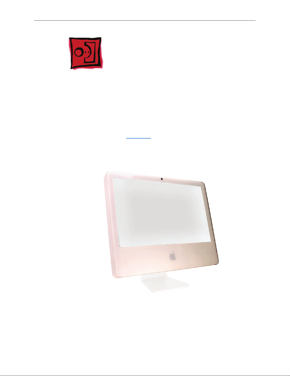
Product View
General Information
What’s New
October 2006
•
EMI tape photos (922-4786 and 922-5026), used to repair torn and damaged EMI shielding,
have been added to the EMI Shielding section in this chapter.
iMac G5 (20-inch iSight) Take Apart — General Information 6

Tools Required
The following tools are required to service the computer. Note that a special access card (part
922-7172) is required to open the front bezel.
ESD-safe workstation and mat
•
Soft, clean towel or cloth (to protect the display and removed parts from scratches)
•
Access card (part 922-7172)
•
Black stick (or other nonconductive nylon or plastic at-blade tool)
•
Phillips #1 screwdriver
•
Phillips #2 screwdriver
•
Torx T8 screwdriver (magnetized)
•
Torx T6 screwdriver (magnetized)
•
Torx T10 screwdriver (magnetized)
•
Flat-blade screwdriver
•
Orientation
For most repairs, the unit should be placed screen-side up, with the bottom facing toward you.
Most photos in this manual reect that orientation. The DIMM slot is located beneath the front
bezel and is more easily accessed with the unit face-down on a soft, clean cloth.
Serial Number Location
iMac G5 (iSight) serial numbers are located on the bottom of the computer stand.
iMac G5 (20-inch iSight) Take Apart — General Information 7
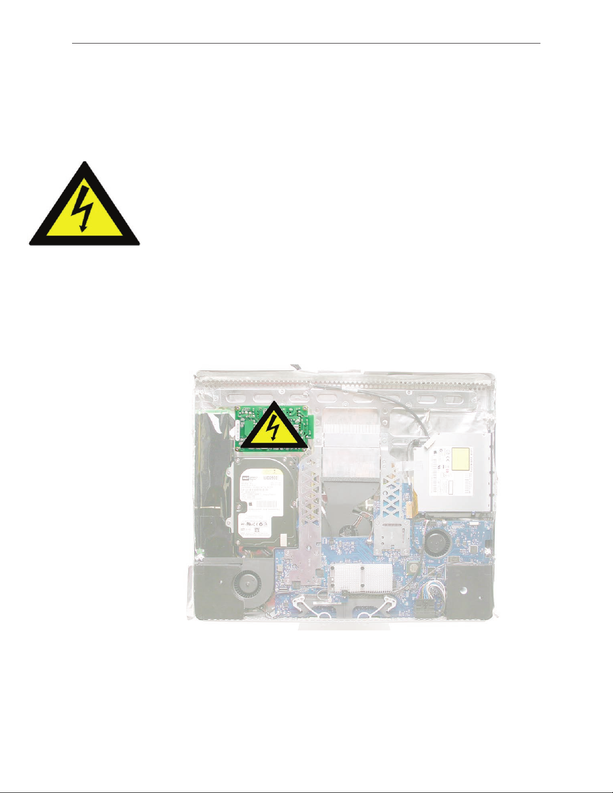
Safety
Warning: When the iMac G5 (iSight) is under power, be aware that the power supply contains
high voltages that pose a potential hazard to your personal safety. Never work on or near the
power supply with the unit powered on, and as a further precaution always make sure the unit is
unplugged when working on it with the front bezel removed.
WARNING: HIGH VOLTAGE
Text or photographs marked by this symbol indicate that a potential hazard to your personal
safety exists from a high voltage source.
The AC/DC power supply board is a high voltage source with the unit under power, and remains
powered up whenever the system is plugged in, whether or not the system is turned on. Use
extreme caution when troubleshooting the system with the front bezel removed.
Disconnect power to the system before performing maintenance.
•
Don’t work alone. In the event of an electrical shock it is important to have another
•
individual present who can provide assistance.
Keep one hand in your pocket when working on any iMac G5 (iSight) that is plugged in.
•
This will help ensure that your body does not provide a path to ground in the event that
you accidentally make contact with the line voltage.
Don’t wear jewelry, watches, necklaces, or other metallic articles that could present a risk
•
if they accidentally make contact with the power supply circuitry.
iMac G5 (20-inch iSight) Take Apart — General Information 8

Opening the Computer
Apple authorized, desktop certied technicians only should ever remove the front bezel on the
iMac G5 (iSight). When the front bezel is removed, be sure to always ground yourself and follow
ESD-safe repair practices
Removing the front bezel requires using a special access card (part 922-7172) to release latches
located inside the upper corners of the front bezel. Slightly bending the upper quarter of the
access tool card will help engage the latch more securely.
As you are inserting the card to disengage the latch you should squeeze the top of the bezel,
that will help take pressure o of the latch and enable it to open easier. Note: If the bezel won’t
open, try cutting the card lengthwise into 3/4 inch or 1.5 cm strips. Insert the card again, aimed
straight up, and try again.
Once the card has been released it is safe to open the bezel. See the Front Bezel Take Apart
procedure for more information.
Access Tool Modication
If you wish to modify the access card tool, order kit 076-1213. The kit contains an access card and
a piece of EMI gasket that can be cut and added to the top of the card. The additional thickness
on the card will improve the chances of making contact with each bezel latch.
Remove the tape on the gasket to expose the sticky side of the gasket. Attach the sticky side
1.
of the EMI gasket to the top of the access card.
iMac G5 (20-inch iSight) Take Apart — General Information 9

Cut the EMI gasket to the edge of the access card.
2.
Using packing tape, or something equivalent, fold the tape over the EMI gasket to attach the
3.
gasket to the card.
iMac G5 (20-inch iSight) Take Apart — General Information 10

Bend the card at a slight angle at the top to make sure the card makes contact with each
4.
latch.
Refer to the Front Bezel take-apart procedure for complete instructions.
5.
iMac G5 (20-inch iSight) Take Apart — General Information 11
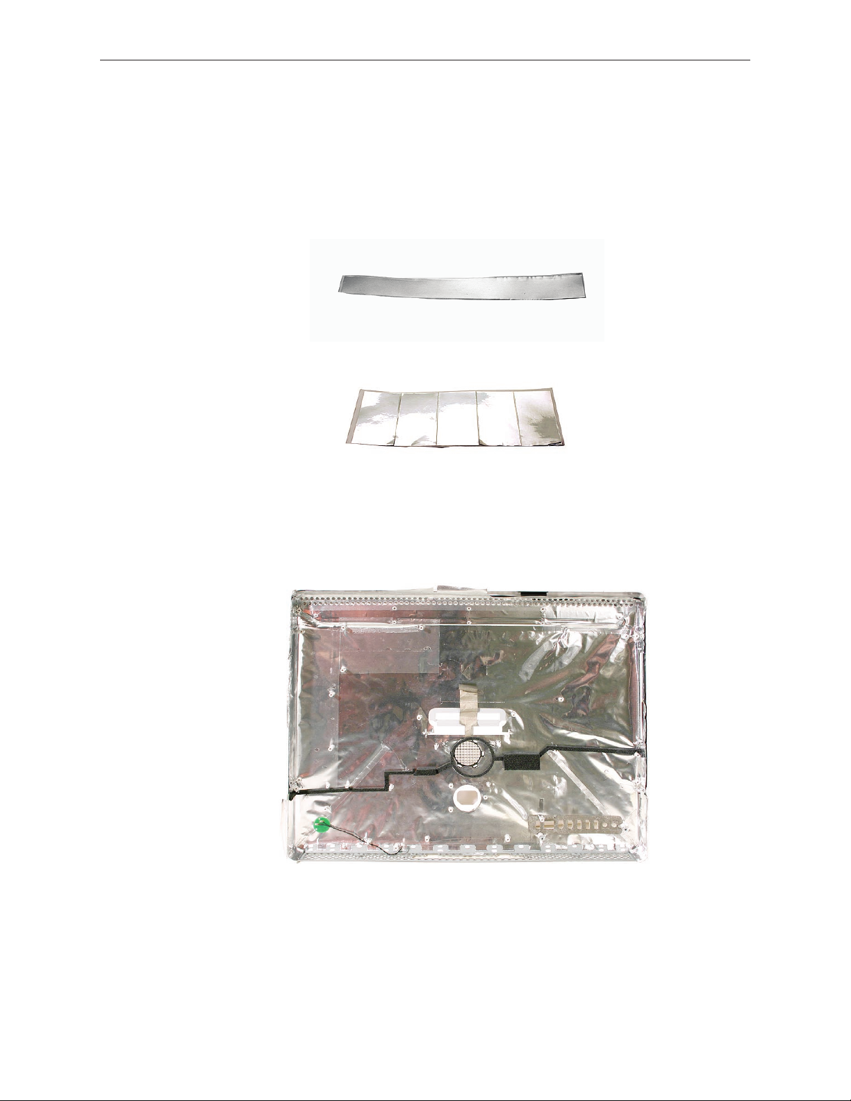
EMI Shielding
The iMac enclosure is wrapped in EMI shielding that is easily torn and damaged. To maintain
a properly shielded unit, you must repair all accidental tears and cracks to the shielding by
covering them with EMI tape. Order EMI tape, part number 922-4786 (a long, thin strip) or 922-EMI tape, part number 922-4786 (a long, thin strip) or 9225026 (short, wide strips).
Cover nicks with EMI tape. Pay particular attention to the EMI shielding inside the rear housing,
shown below. The EMI shield is easily damaged when replacing modules.
iMac G5 (20-inch iSight) Take Apart — General Information 12
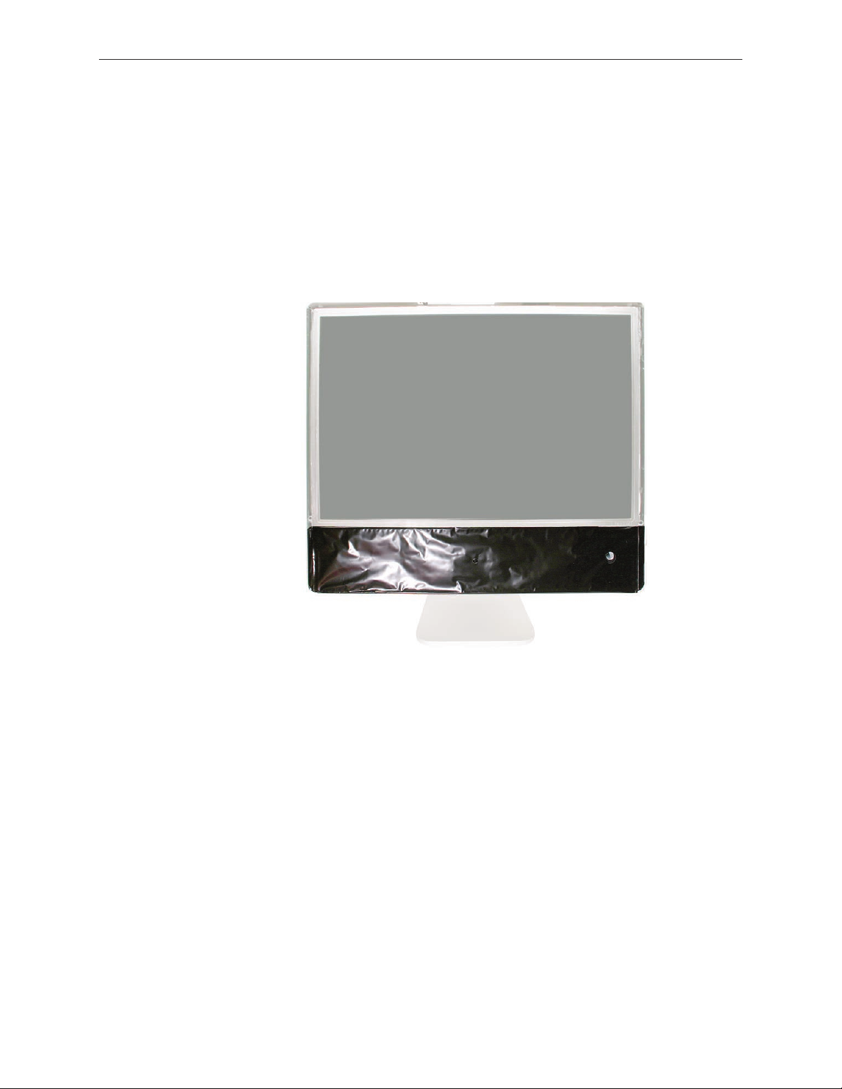
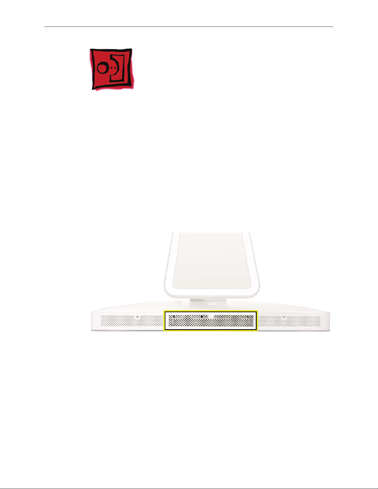
Lower EMI Shield
EMI tape covers the top and sides of the display panel, and the lower EMI shield covers the logic
board along the bottom of the unit. The EMI tape and lower EMI shield are easily damaged when
removed, and removal is necessary in order to access most components within the unit.
Should the EMI tape that seals the display, or the EMI shield covering the bottom of the enclosure
(see photo below) accidentally tear, use the EMI tape (922-4786 or 922-5026) to repair and
completely seal the unit.
iMac G5 (20-inch iSight) Take Apart — General Information 13
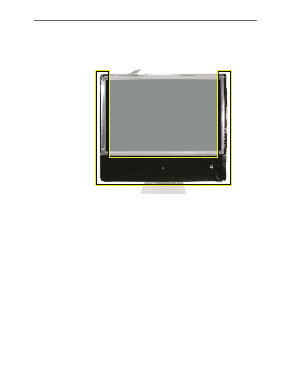
When properly repaired, all edges shown below will be wrapped by EMI tape, and the tape
securely adhered to all edges. Use a “black stick” to atten the EMI tape tightly and rub out air
pockets and wrinkles.
Speakers
The speakers shown in this manual are black, however the nal production units all have white
speakers, as shown in the GSX database. Refer to the speaker part number 922-6988 for details
iMac G5 (20-inch iSight) Take Apart — General Information 14
Access Door
Tools
Phillips #2 screwdriver
•
ESD-safe workstation and mat
•
Soft , clean towel or cloth
•
Preliminary Steps
Before you begin, lay the computer down so the panel is face down and the bottom is facing
you.
Part Location
iMac G5 (20-inch iSight) Take Apart — Access Door 15

Removing the Access Door
Raise the stand and use a Phillips #2 screwdriver, to loosen the two captive access door
1.
screws.
Warning: The ambient light sensor is located between the two screws, as shown in the
graphic. Don’t mistake the ambient light sensor for a screw. Sticking a screw driver or other
sharp object in the ambient light sensor could damage the computer.
Remove the access door.
2.
Replacing the Access Door
Replace the access door using it to push the rings into the memory compartment.
1.
Use a Phillips #2 screwdriver to tighten the captive screws.
2.
iMac G5 (20-inch iSight) Take Apart — Access Door 16
Front Bezel
Tools
Torx T8 screwdriver
•
Access card tool 922-7172
•
ESD mat, soft , clean towel or cloth
•
Preliminary Steps
Before you begin, remove the access door.
Part Location
iMac G5 (20-inch iSight) Take Apart — Front Bezel 17
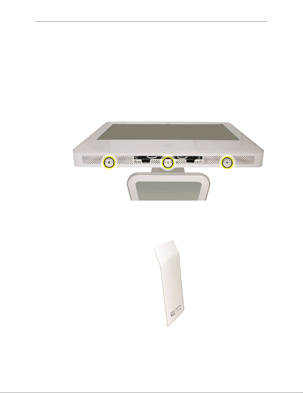
Removing the Front Bezel
Position unit on rear cover (back).
1.
Tilt up the front bezel and remove three screws along the bottom.
2.
Warning: The ambient light sensor is located next to the center screw. Don’t mistake the
ambient light sensor for a screw. Sticking a screwdriver or other sharp object in the ambient
light sensor could damage the computer.
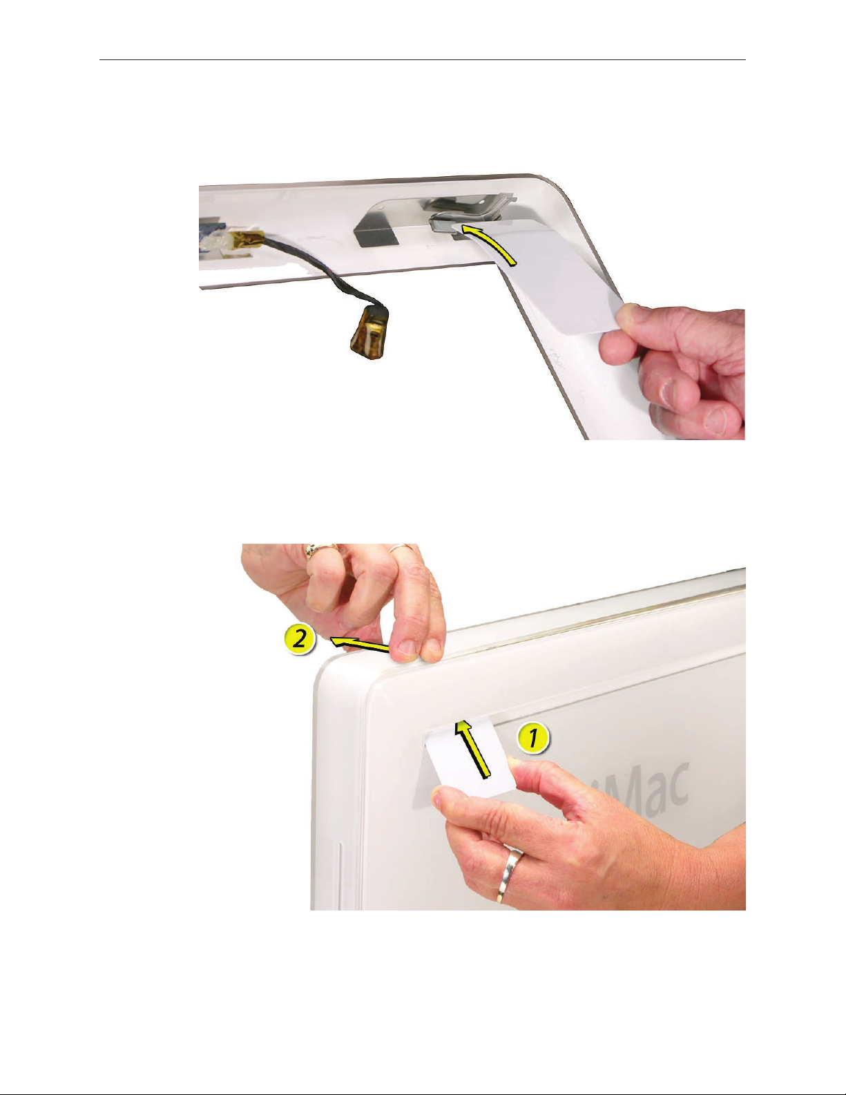
Slightly bending the upper quarter of the access tool card will help engage the latch more
3.
securely. Refer to the Access Tool Modication if the bezel is dicult to remove.
iMac G5 (20-inch iSight) Take Apart — Front Bezel 18
This picture shows how the access tool works. Pushing the tool up the vent on the rear cover
4.
releases the latches on the inside of the front bezel. Refer to the next step for the procedure.
Start on the left side (looking from the back of the unit). As you insert the card to disengage
5.
the latch, squeeze the top of the bezel, that will help take pressure o of the latch and
enable it to open easier. As the bezel releases, pull the bezel away from the rear housing.
iMac G5 (20-inch iSight) Take Apart — Front Bezel 19

Repeat step 5 to release the locking latch in the right corner. Again, pull the bezel away as
6.
the card releases the latch.
If the bezel won’t release, pull the bottom of the bezel out a bit and insert the access card
7.
again.
iMac G5 (20-inch iSight) Take Apart — Front Bezel 20

Repeat step 7 for the left side.
8.
Once the access card has been removed, it is safe to open the bezel. Position the unit on an
9.
ESD mat, with the bottom facing toward you. Lift up the top of the bezel and pull it up and
slightly toward you. Caution: Make sure the memory eject rings are not protruding from the
access door when you lift the bezel or you could bend or damage the eject rings.
iMac G5 (20-inch iSight) Take Apart — Front Bezel 21

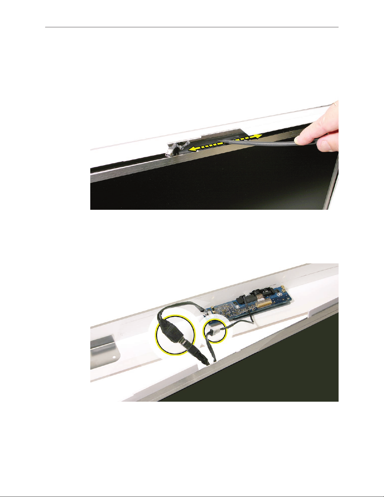
Swing the bezel up so you can disconnect two cables on the camera board at the top of the
10.
bezel.
Disconnect the camera and microphone cables from the camera board.
11.
Lift the front bezel o the computer. Note the microphone is part of the front bezel
12.
assembly.
iMac G5 (20-inch iSight) Take Apart — Front Bezel 22
Replacing the Front Bezel
Make sure the black EMI shielding along the top of the LCD panel is not in the way of the
1.
bezel latches when you lower the front bezel onto the computer. Use a black stick to press
(re-stick) the EMI shielding onto the panel.
Connect the camera and microphone cables (on the camera board) to the cables sticking
2.
out of the top of the computer.
iMac G5 (20-inch iSight) Take Apart — Front Bezel 23

Tuck the cables neatly into the channel on the rear housing.
3.
Continue to lower the font bezel down over the pull rings (in the memory compartment)
4.
and then press the top corners of the front bezel to connect the magnetic latches. Note:
check that the latches are connected by lifting the front bezel at each corner.
Replace the three front bezel screws along the bottom of the computer.
5.
Replace the access door; tighten the two captive screws.
6.
iMac G5 (20-inch iSight) Take Apart — Front Bezel 24

Camera Board
Tools
Torx T6 screwdriver
•
ESD mat, soft , clean towel or cloth
•
Preliminary Steps
Before you begin, remove the access door and front bezel.
Part Location
iMac G5 (20-inch iSight) Take Apart — Camera Board 25

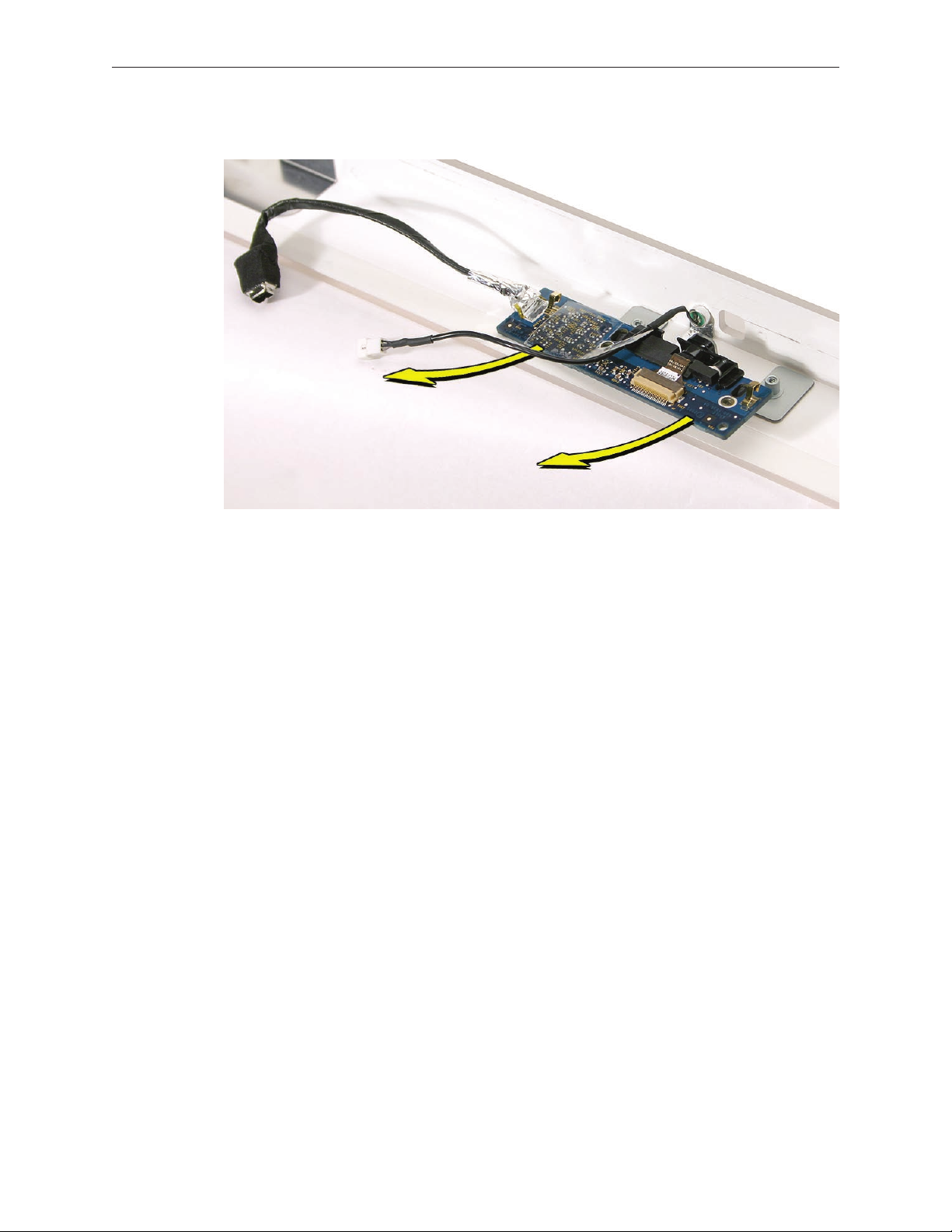
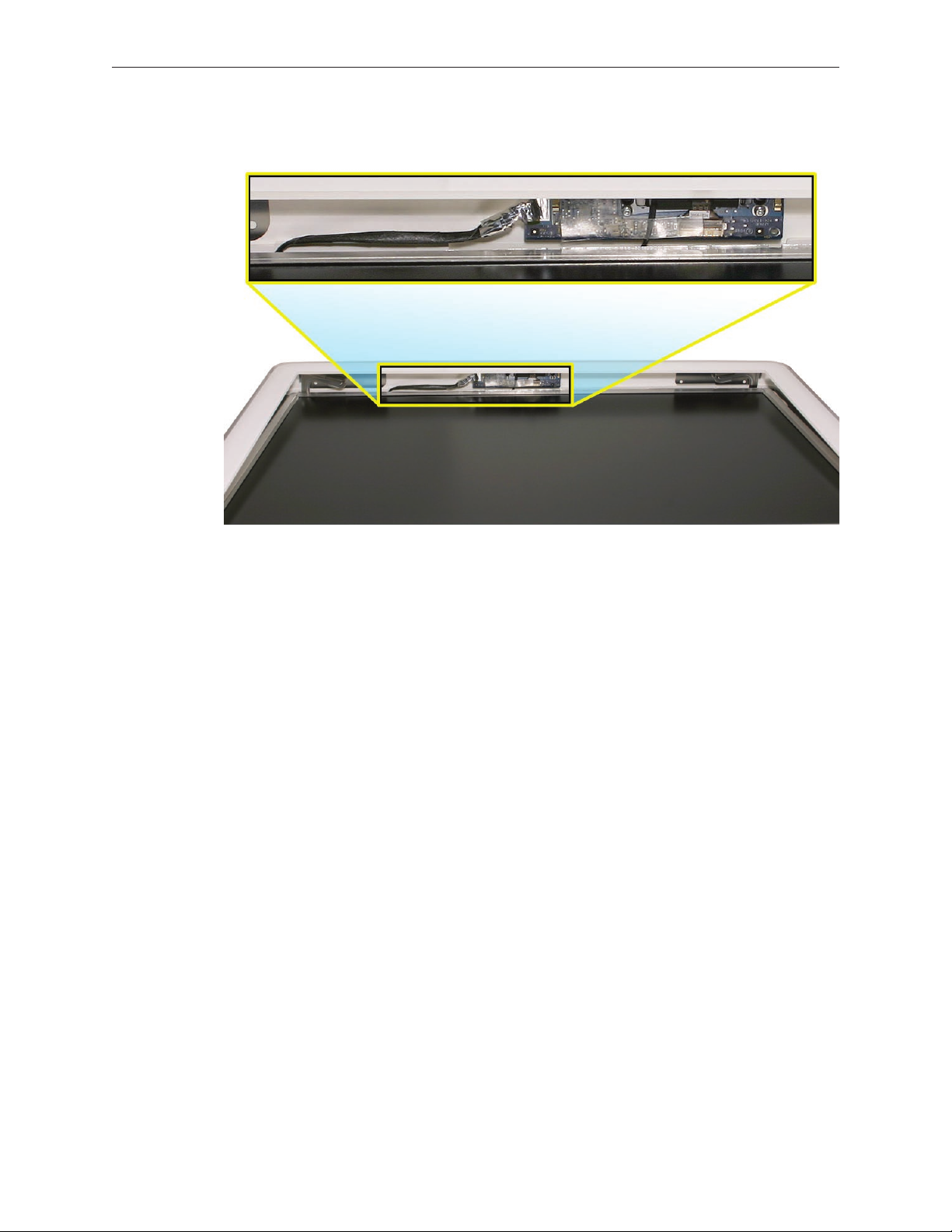
Removing the Camera Board
The camera board and cables are visible as you lift the front bezel o the computer.
1.
Disconnect the camera and microphone cables.
2.
iMac G5 (20-inch iSight) Take Apart — Camera Board 26

3.
Remove the two T6 screws on the camera board.
4.
Peel back the clear mylar material to free the microphone cable from the camera board.
iMac G5 (20-inch iSight) Take Apart — Camera Board 27
Remove the camera board from the front bezel.
5.
iMac G5 (20-inch iSight) Take Apart — Camera Board 28

Replacing the Camera Board
Replace the camera board on the front bezel. Carefully align and insert the camera lens until
1.
it is snug in the bezel aperture
Replace the two screws on the camera board. Route the microphone cable under the clear
2.
mylar.
Connect the camera and microphone cables.
3.
iMac G5 (20-inch iSight) Take Apart — Camera Board 29
Tuck the camera board cables neatly into the channel on the rear housing.
4.
Continue to lower the font bezel down over the pull rings (in the memory compartment)
5.
and then lower the top corners of the front bezel so they connect with the magnetic latches.
Note: check that the latches are connected by lifting the front bezel at each corner.
Replace the three bezel screws along the bottom of the computer.
6.
Replace the access door; tighten the two captive screws
7.
iMac G5 (20-inch iSight) Take Apart — Camera Board 30
 Loading...