

Service Source
iMac G5 (17-inch iSight)
Updated: 1 August 2006
© 2005 Apple Computer, Inc. All rights reserved.

iMac G5 (17-inch iSight)
Contents
Take Apart
General Information 6
Product View 6
What’s New? 7
Orientation 7
Serial Number Location 7
Safety 8
Opening the Computer 9
Access Tool Modication 9
EMI Shielding 12
Lower EMI Shield 13
Access Door and Memory 16
Front Bezel 19
Camera Board 2
6
Lower EMI Shield 28
IR Board 3
0
LCD Display 32
TMDS Cable 39
Inverter 4
2
Speakers 46
CPU Fan 4
9
Optical Drive 51
Hard Drive 58
DC-DC Board 64
Power Supply 6
7
Logic Board 7
1
ii

Optical Drive Fan 77
Hard Drive Fan 79
AC Power Inlet 81
Ambient Light Sensor Board 85
Clutch 89
Wireless Antenna 94
DC Power Cable 98
Camera Cable 101
Chassis 105
Rear Housing 109
Troubleshooting
General Information 111
Serial Number Location 111
Accessing the Diagnostic LEDs 112
Testing Under Power 118
SMU (System Management Unit) 120
Resetting the SMU (System Management Unit) 120
Ports 121
DDR Memory 121
Symptom Charts 122
How to Use the Symptom Charts 122
Power Issues 123
No Video 127
LCD Display 130
Hard Drive 131
Optical Drive 132
Fan Sound 137
AirPort/Bluetooth 140
IR Remote 142
IR Sensor/Receiver 143
Built-in iSight Camera 144
Speakers 146
Mouse 148
Keyboard 149
Error Beep(s) 150
USB 151
iii

Views
iMac G5 (17-inch iSight)—Upper Exploded View 153
iMac G5 (17-inch iSight)—Lower Exploded View 154
Screw Chart 155
iv

Service Source
Take Apart
iMac G5 (17-inch iSight)
© 2005 Apple Computer, Inc. All rights reserved.
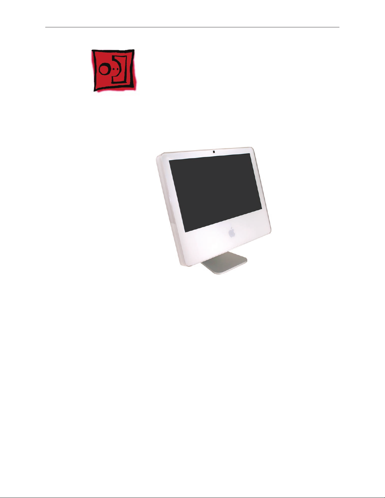
Product View
General Information
Tools Required
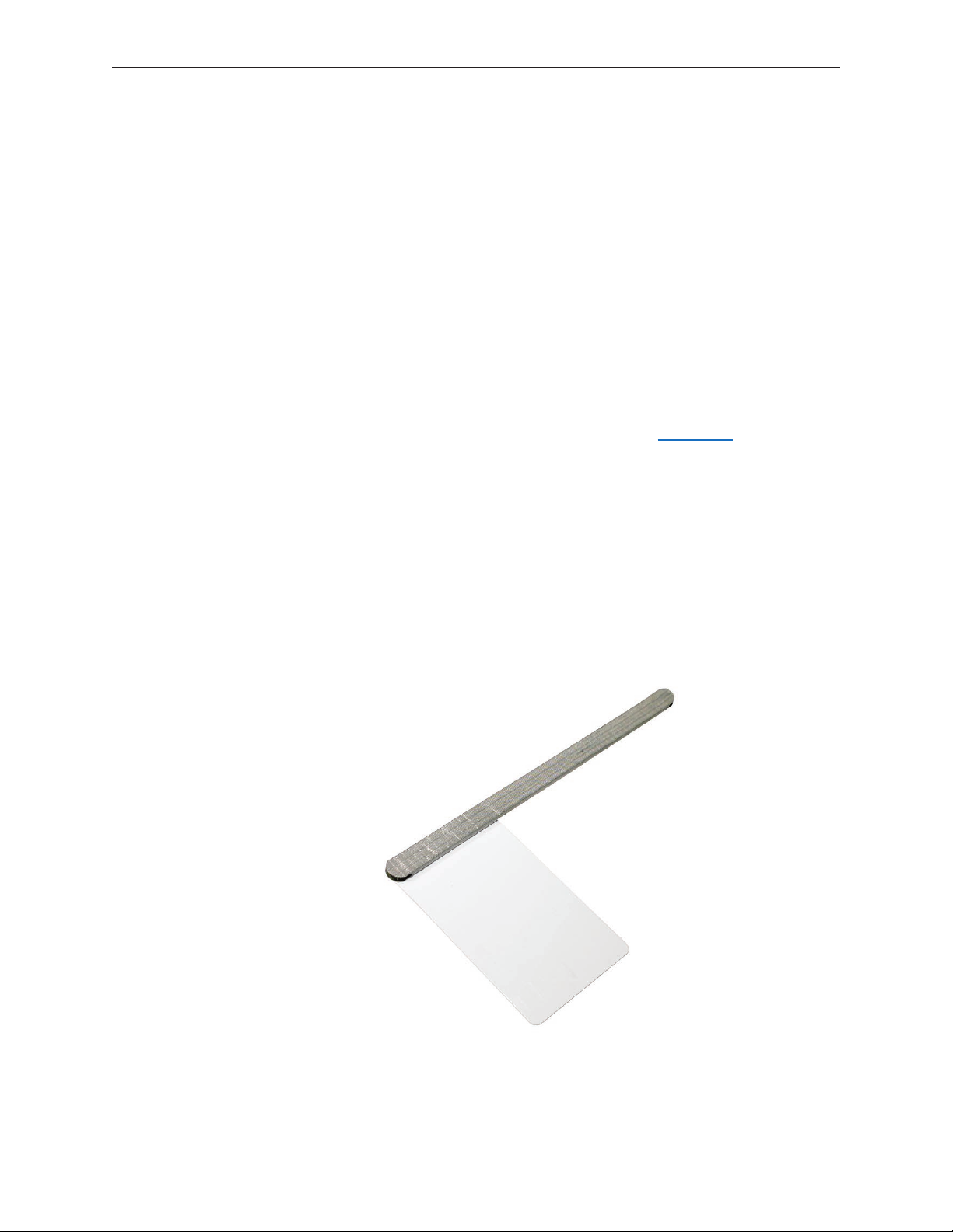
The following tools are required to service the computer. Note that a special access card (part
922-7172) is required to open the front bezel.
ESD-safe workstation and mat
•
Soft, clean towel or cloth (to protect the display and removed parts from scratches)
•
Access card (part 922-7172)
•
“black stick” (or other nonconductive nylon or plastic at-blade tool)
•
Phillips #1 screwdriver
•
Phillips #2 screwdriver
•
Torx T8 screwdriver (magnetized)
•
Torx T6 screwdriver (magnetized)
•
Torx T10 screwdriver (magnetized)
•
Flat-blade screwdriver
•
iMac G5 (17-inch iSight) Take Apart — General Information 6
What’s New?
August 2006
Updated the Hard Drive section in the Take Apart chapter. Note: Make sure to transfer the
•
temperature sensor to the replacement hard drive. Use the double-stick tape enclosed with
the replacement hard drive to attach the sensor.
Orientation
For most repairs, the unit should be placed screen-side up, with the bottom facing toward you.
Most photos in this manual reect that orientation. The DIMM slot is located beneath the front
bezel and is more easily accessed with the unit face-down on a soft, clean cloth.
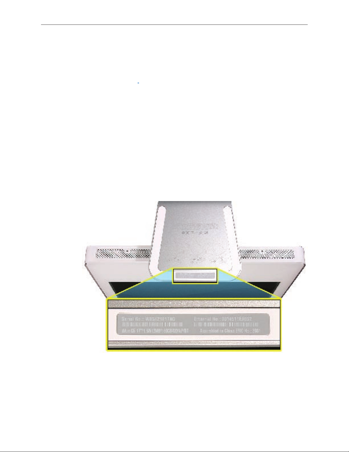
Serial Number Location
iMac G5 (iSight) serial numbers are located on the bottom of the computer stand as shown
below.
iMac G5 (17-inch iSight) Take Apart — General Information 7
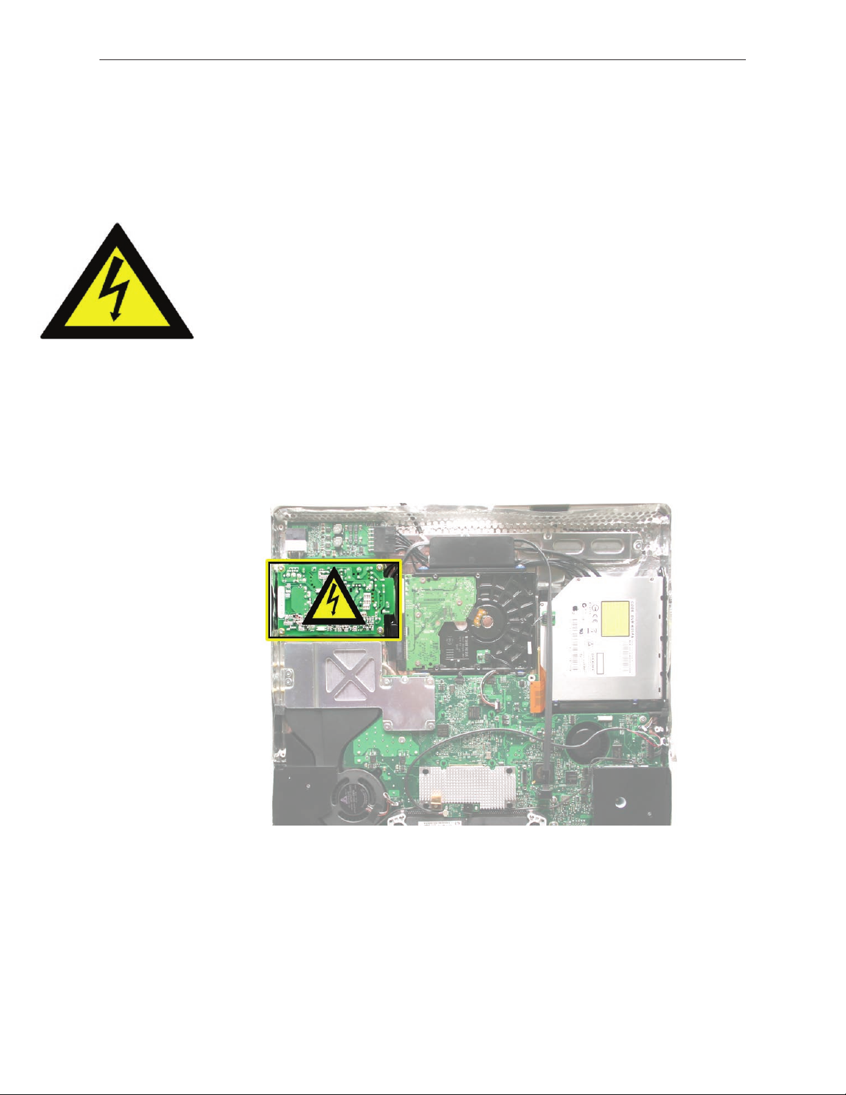
Safety
Warning: When the iMac G5 (iSight) is under power, be aware that the power supply contains
high voltages that pose a potential hazard to your personal safety. Never work on or near the
power supply with the unit powered on, and as a further precaution always make sure the unit is
unplugged when working on it with the front bezel removed.
WARNING: HIGH VOLTAGE
Text or photographs marked by this symbol indicate that a potential hazard to your personal
safety exists from a high voltage source.
The AC/DC power supply board is a high voltage source with the unit under power, and remains
powered up whenever the system is plugged in, whether or not the system is turned on. Use
extreme caution when troubleshooting the system with the front bezel removed.
Disconnect power to the system before performing maintenance.
•
Don’t work alone. In the even of an electrical shock it is important to have another
•
individual present who can provide assistance.
Keep one hand in your pocket when working on any iMac G5 (iSight) that is plugged in.
•
This will help ensure that your body does not provide a path to ground in the event that
you accidentally make contact with the line voltage.
Don’t wear jewelry, watches, necklaces, or other metallic articles that could present a risk
•
if they accidentally make contact with the power supply circuitry.
iMac G5 (17-inch iSight) Take Apart — General Information 8
Opening the Computer
Apple authorized, desktop certied technicians only should ever remove the front bezel on the
iMac G5 (iSight). When the front bezel is removed, be sure to always ground yourself and follow
ESD-safe repair practices
Removing the front bezel requires using a special access card (part 922-7172) to release latches
located inside the upper corners of the front bezel. Slightly bending the upper quarter of the
access tool card will help engage the latch more securely.
As you are inserting the card to disengage the latch you should squeeze the top of the bezel,
that will help take pressure o of the latch and enable it to open easier. Note: If the bezel won’t
open, try cutting the card lengthwise into 3/4 inch or 1.5 cm strips. Insert the card again, aimed
straight up, and try again.
Once the card has been released it is safe to open the bezel. See the Front Bezel Take Apart
procedure for more information.
Access Tool Modication
If you wish to modify the access card tool, order kit 076-1213. The kit contains an access card and
a piece of EMI gasket that can be cut and added to the top of the card. The additional thickness
on the card will improve the chances of making contact with each bezel latch.
Remove the tape on the gasket to expose the sticky side of the gasket. Attach the sticky side
1.
of the EMI gasket to the top of the access card.
iMac G5 (17-inch iSight) Take Apart — General Information 9
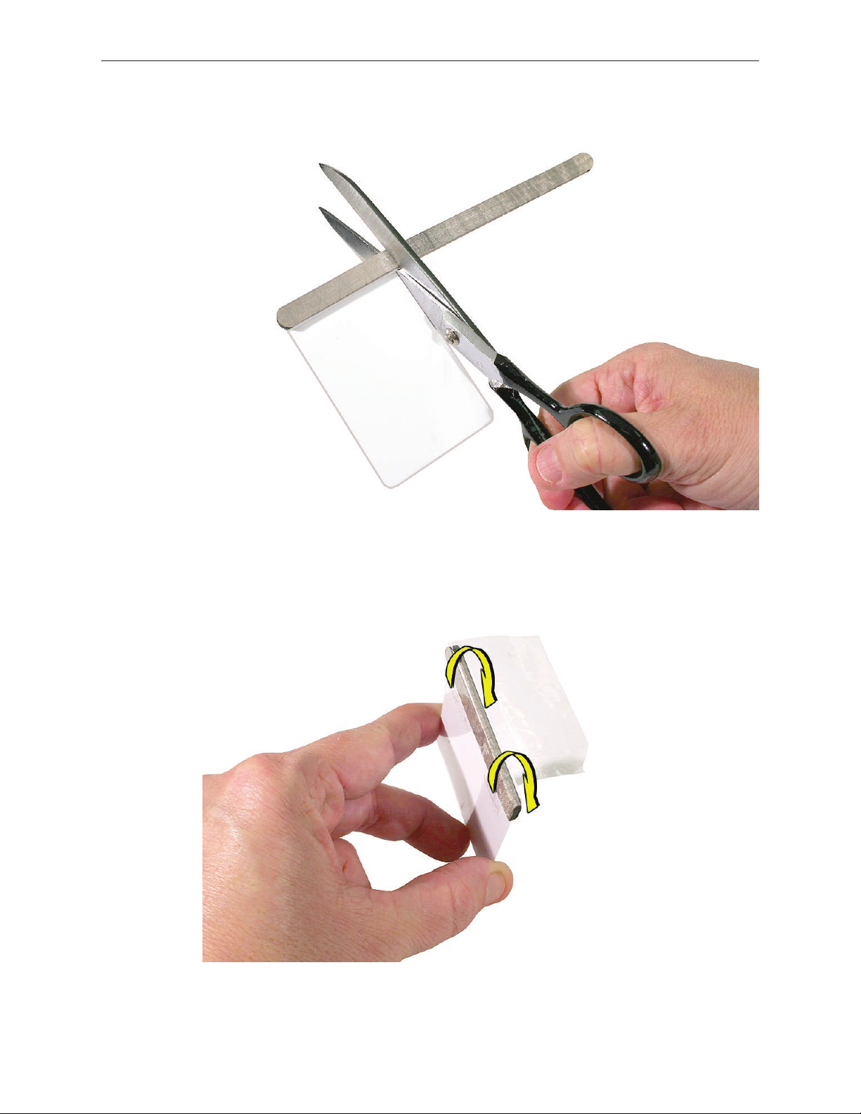
Cut the EMI gasket to the edge of the access card.
2.
Using packing tape, or something equivalent, fold the tape over the EMI gasket to attach the
3.
gasket to the card.
iMac G5 (17-inch iSight) Take Apart — General Information 10
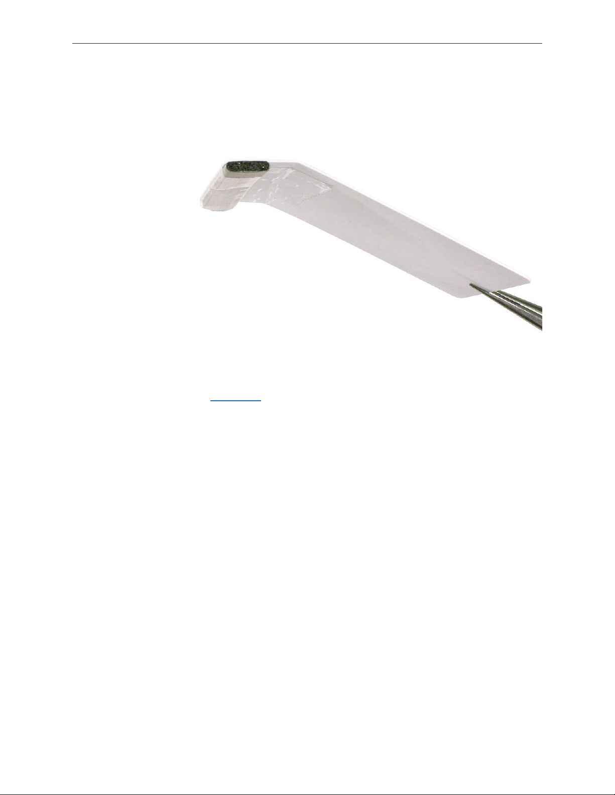
Bend the card at a slight angle at the top to make sure the card makes contact with each
4.
latch.
Refer to the Front Bezel take-apart procedure for complete instructions.
5.
iMac G5 (17-inch iSight) Take Apart — General Information 11
EMI Shielding
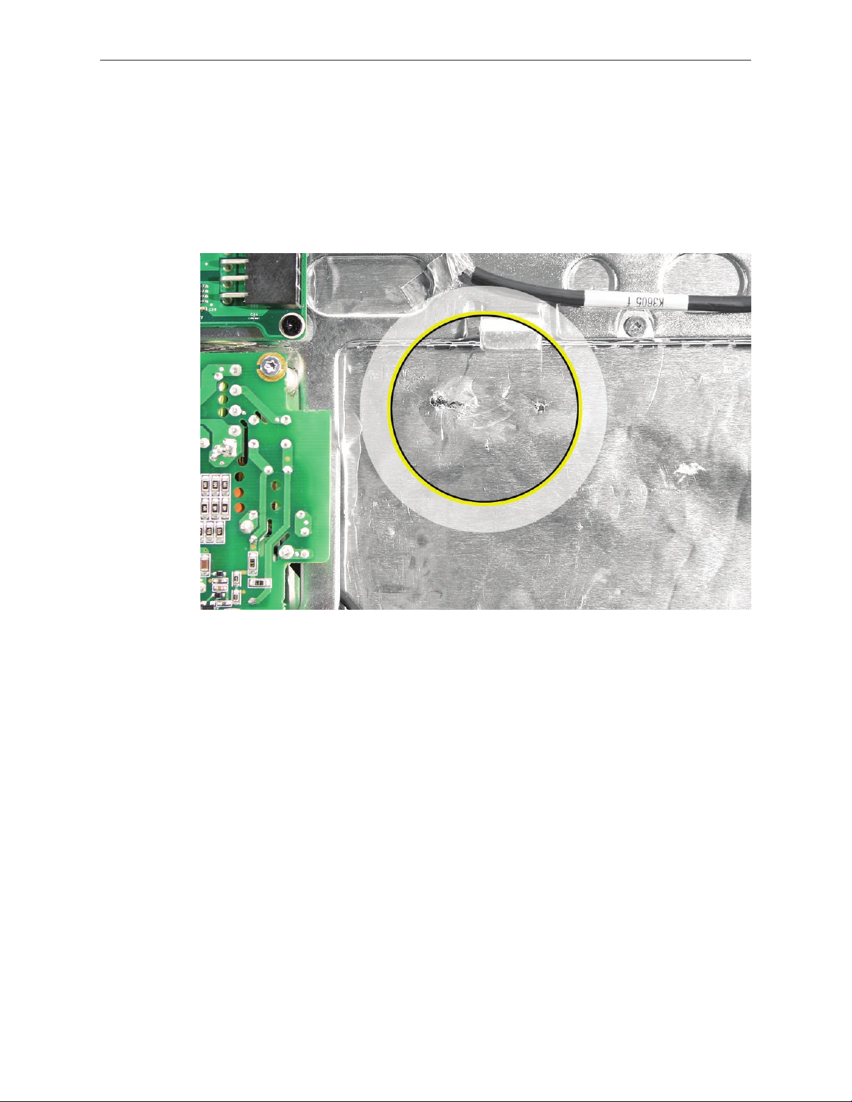
The iMac G5 (iSight) enclosure is wrapped in EMI shielding that is easily torn and damaged. To
maintain a properly shielded unit, you must repair all accidental tears and cracks to the shielding
by covering them with EMI tape.
Cover nicks, such as the those shown below, with EMI tape.
iMac G5 (17-inch iSight) Take Apart — General Information 12
Pay particular attention to the faraday shielding inside the rear housing, shown below. The
faraday shield is easily damaged when replacing the hard drive.
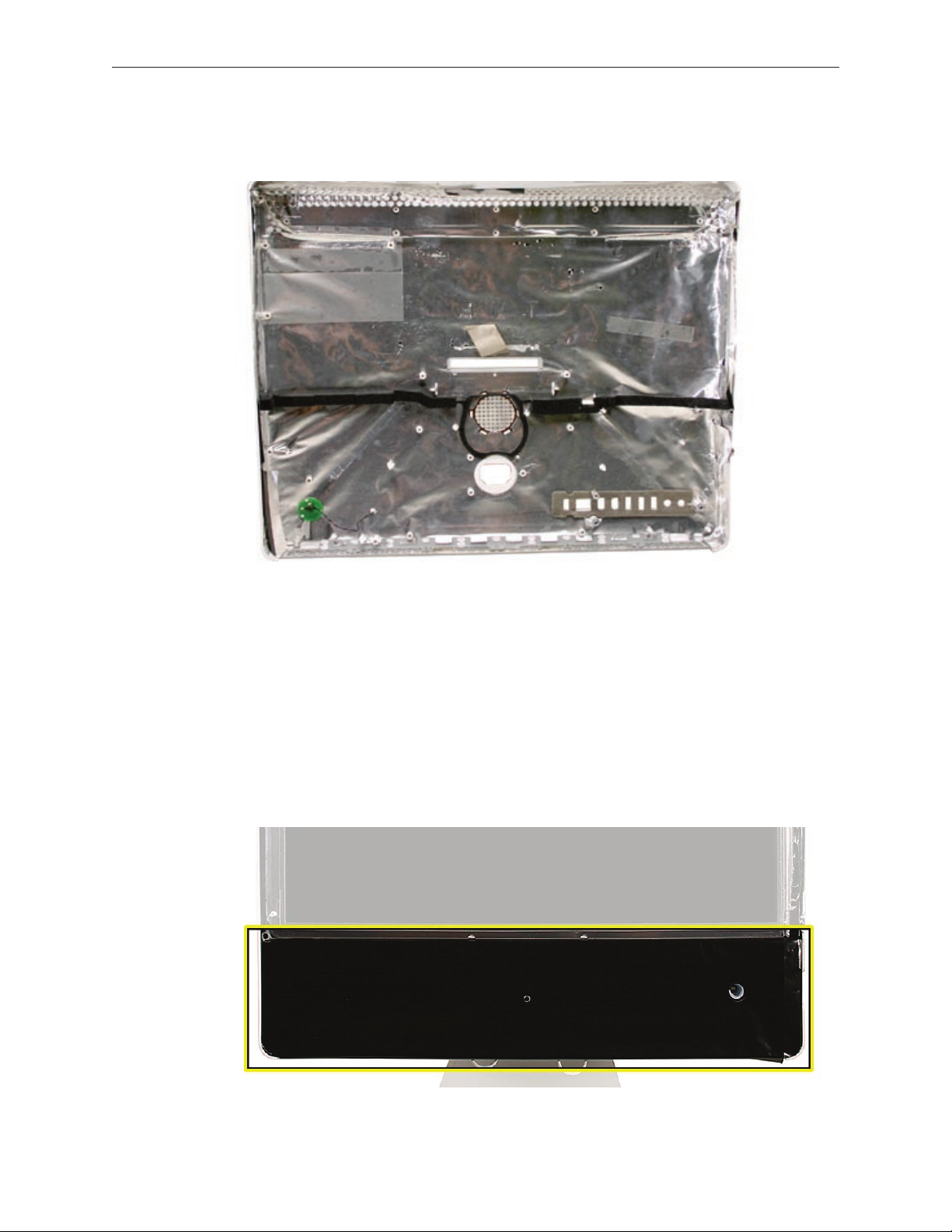
Lower EMI Shield
EMI tape covers the top and sides of the display panel, and the lower EMI shield covers the logic
board along the bottom of the unit. The EMI tape and lower EMI shield are easily damaged when
removed, and removal is necessary in order to access most components within the unit.
Should the EMI tape that seals the display, or the EMI shield covering the bottom of the enclosure
(see photo below) accidentally tear, use EMI tape to repair and completely seal the unit.
iMac G5 (17-inch iSight) Take Apart — General Information 13
When properly repaired, all edges shown below will be wrapped by EMI tape, and the tape
securely adhered to all edges. Use a “black stick” to atten the EMI tape tightly and rub out air
pockets and wrinkles.
iMac G5 (17-inch iSight) Take Apart — General Information 14

iMac G5 (17-inch iSight) Take Apart — General Information 15
Access Door and Memory
Tools
Phillips #2 screwdriver.
•
ESD-safe workstation and mat
•
Soft, clean towel or cloth
•
Preliminary Steps
Shut down the computer and unplug all external cables except the power cord.
1.
Place a soft, clean towel or cloth on the ESD mat. Grasp the sides of the unit and slowly lay it
2.
screen-down on the cloth, with the bottom facing you.
Touch the metal memory access cover to discharge any static electricity from your body.
3.
Important: Always discharge static before you touch any parts such as the memory board.
To avoid generating static electricity, do not walk around the room until you have nished
replacing the memory.
Unplug the power cord and put on an ESD wrist strap.
4.
iMac G5 (17-inch iSight) Take Apart — Access Door & Memory 16
Remove the Access Door and Memory
Raise the stand and use a Phillips #2 screwdriver to loosen the two captive screws that
1.
secure the memory access door. Remove the access door.
Caution: The ambient light sensor is located between the two screws. Don’t mistake the
ambient light sensor for a screw.
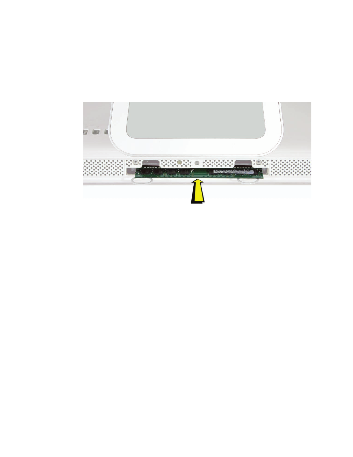
To eject any optional memory, pull out simultaneously the two rings protruding from the
2.
memory slot. The memory will poke out from the memory slot. Grasp the memory by its
edges only and remove it.
iMac G5 (17-inch iSight) Take Apart — Access Door & Memory 17
Replace the Memory and Access Door
Grasp the memory module by its edges and insert it into the memory slot as shown below.
1.
Push the edge of the memory module in gently to lock it in place.
Replacement Note: The memory module ts into the slot only one way. When inserted fully,
you should hear a slight click and the two pull rings should retract a bit. Do NOT insert the
memory by pushing in the pull rings.
Position the access door on the rear housing. Lift the stand out of the way and tighten the
2.
two captive mounting screws.
iMac G5 (17-inch iSight) Take Apart — Access Door & Memory 18
Front Bezel
Tools
This procedure requires the following tools:
Access card tool 922-7172
•
Torx T8 screwdriver
•
Preliminary Steps
Before you begin, follow steps for removing the access door.
Remove the Front Bezel
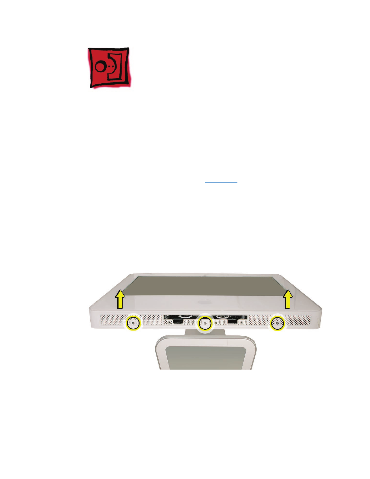
Turn over the unit and place it screen-up on an ESD mat, with the bottom facing toward you.
1.
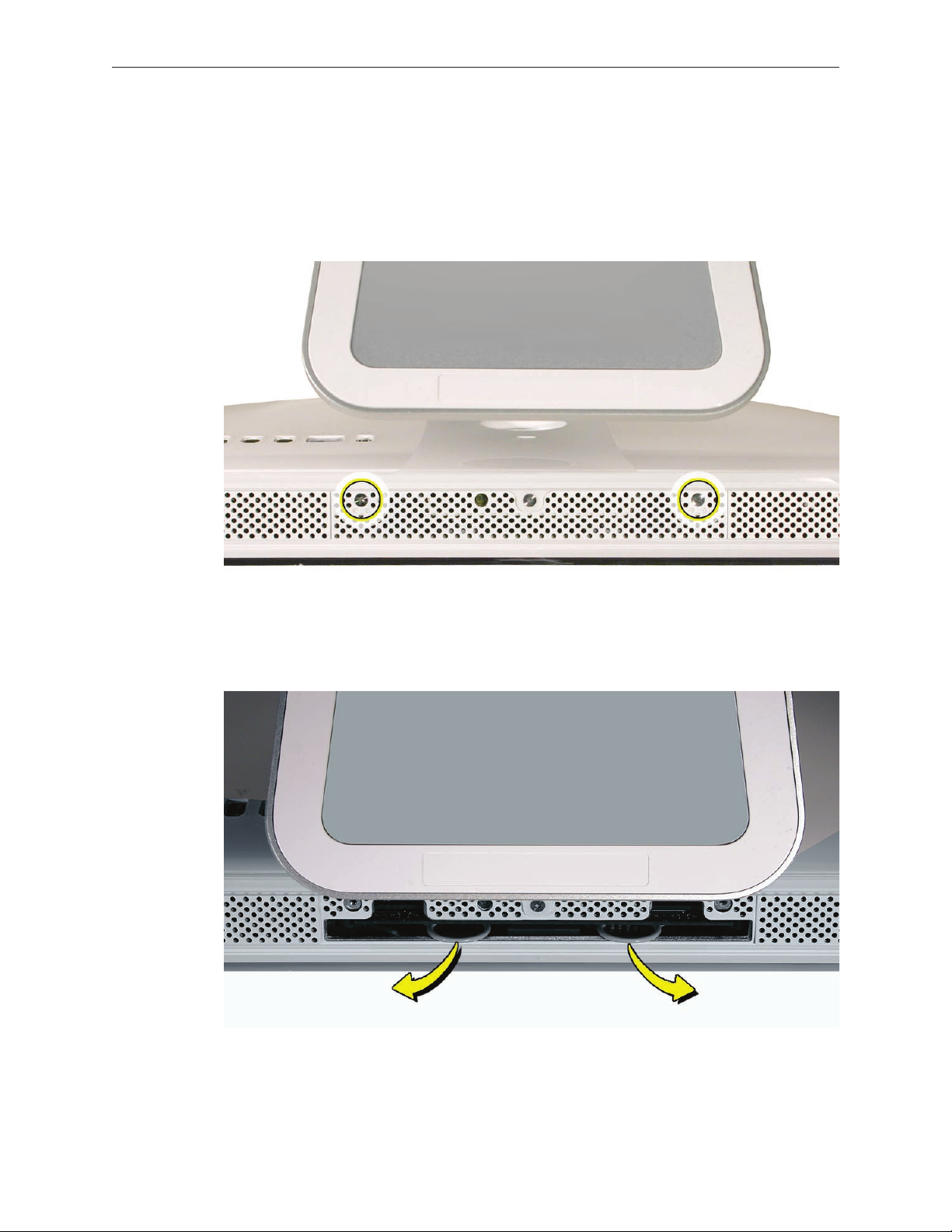
Tilt up the bezel and use a T8 torx screwdriver to remove the three bezel mounting screws.
2.
iMac G5 (17-inch iSight) Take Apart — Front Bezel 19
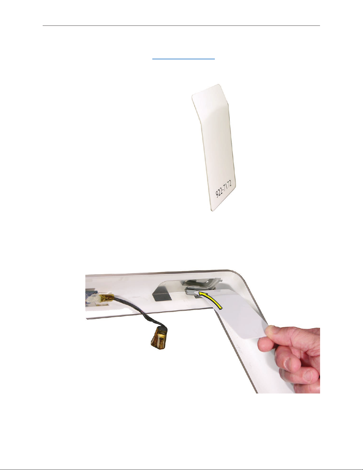
Bending the upper quarter of the access tool card slightly will help engage the latch more
3.
securely. Note: Refer to Access Tool Modication in the General Information chapter if the
bezel is dicult to open.
This picture shows how the access tool works. Pushing the tool up the vent on the rear cover
4.
releases the latches on the inside of the front bezel. Refer to the next step for the procedure.
iMac G5 (17-inch iSight) Take Apart — Front Bezel 20
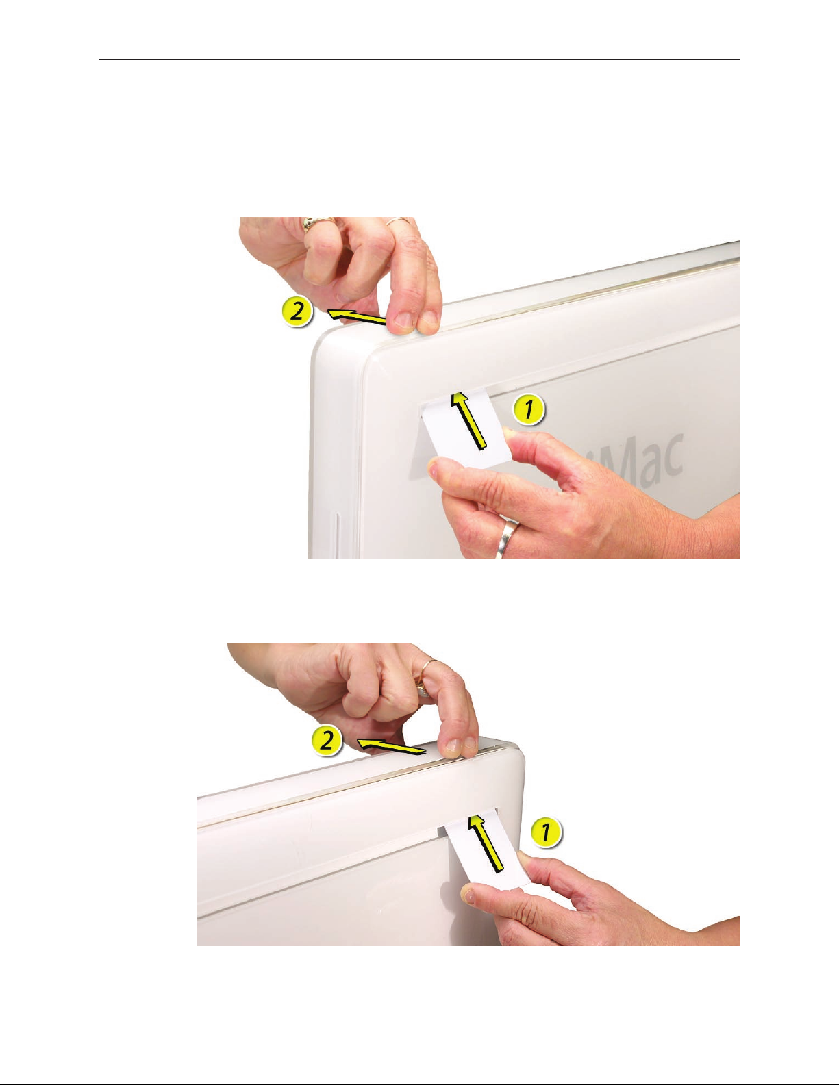
Start on the left side (looking from the back of the unit). As you insert the card to disengage
5.
the latch, squeeze the top of the bezel, that will help take pressure o of the latch and
enable it to open easier. As the bezel releases, pull the bezel away from the rear housing.
Note: If the bezel won’t open, try cutting the card lengthwise into 3/4 inch or 1.5 cm strips.
Insert the card again, aimed straight up, and try again.
Repeat step 5 to release the locking latch in the right corner. Again, pull the bezel away as
6.
the card releases the latch.
iMac G5 (17-inch iSight) Take Apart — Front Bezel 21
If the bezel won’t release, pull the bottom of the bezel out a bit and insert the access card
7.
again.
Repeat step 7 for the left side.
8.
iMac G5 (17-inch iSight) Take Apart — Front Bezel 22
Once the access card has been removed, it is safe to open the bezel. Position the unit on an
9.
ESD mat, with the bottom facing toward you..
Lift the bottom of the front bezel straight up to remove it, and swing the bezel over onto its
10.
top edge so you can disconnect two cables that tether the top of the bezel to the unit.
Caution: Make sure the memory eject rings are not protruding from the bezel when you lift
it or you could bend or damage the rings.
iMac G5 (17-inch iSight) Take Apart — Front Bezel 23
Disconnect the two camera board cables.
11.
If replacing a damaged front bezel, also remove the camera board. See the following
12.
procedure.
Replace the Front Bezel
If necessary, replace the camera board.
1.
Postion the front bezel near the top edge of the unit and connect the two camera board
2.
connectors.
iMac G5 (17-inch iSight) Take Apart — Front Bezel 24
Check and make sure no EMI tape interferes with the locking mechanisms when the bezel is
3.
installed onto the unit. The locking mechanisms must slide into a gap inside the top edge of
the rear housing.
Potition the front bezel around the edges of the unit, push in the memory eject rings, and
4.
press the bezel onto the rear housing.
Note: When pressing the top of the bezel rmly onto the housing you should audibly hear
the locking mechanisms latch onto the housing.
Install the three bezel mounting screws.
5.
Replace the access door.
6.
iMac G5 (17-inch iSight) Take Apart — Front Bezel 25
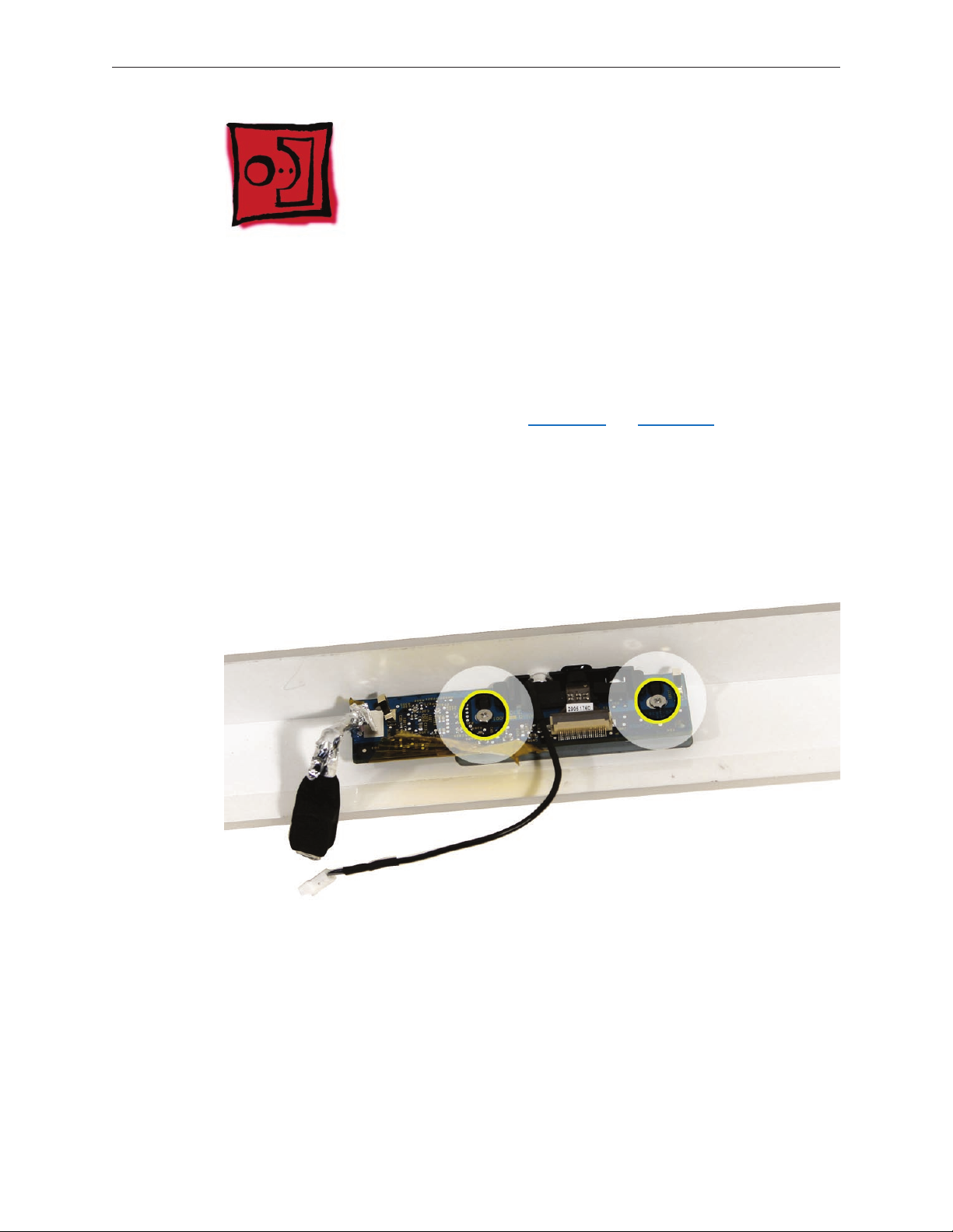
Camera Board
Tools
The only tool required for this procedure is a Phillips #1 screwdriver.
Preliminary Steps
Before you begin, follow steps for removing the access door and front bezel.
Remove the Camera Board
Using the Phillips #1 screwdriver, peel back tape as necessary and remove the two camera
1.
board mounting screws.
Pull the camera board straight out of the lens aperture in the bezel to remove it.
2.
iMac G5 (17-inch iSight) Take Apart — Camera Board 26
Replace the Camera Board
Carefully align and insert the camera lens until it is snug in the bezel aperture.
1.
Install the camera board to the bezel with two mounting screws.
2.
Replace the front bezel.
3.
Replace the access door.
4.
iMac G5 (17-inch iSight) Take Apart — Camera Board 27
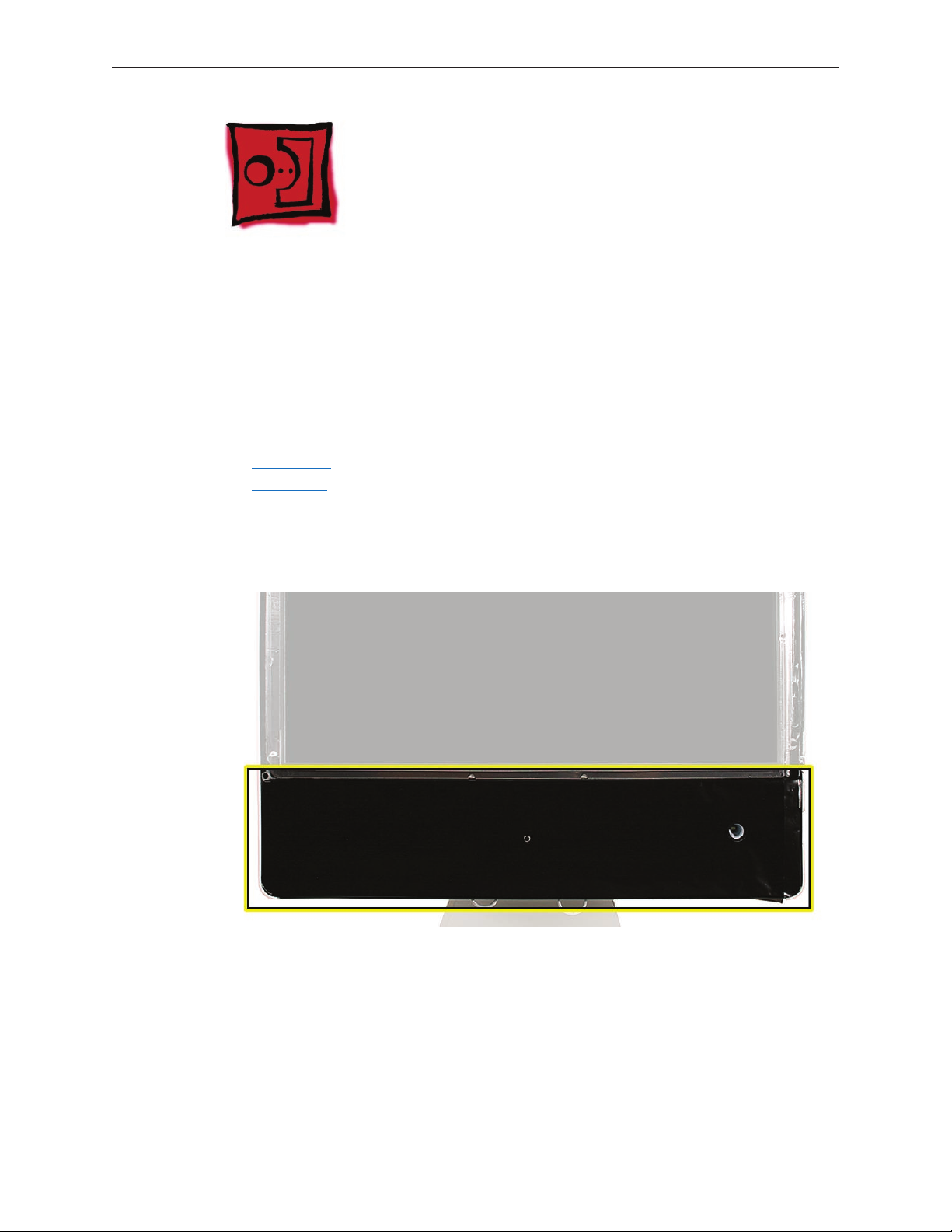
Lower EMI Shield
Tools
The only tool required for this procedure is a “black stick” (or other nonconductive nylon or
plastic at-blade tool).
Preliminary Steps
Before you begin, follow steps for removing the following:
Access door
•
Front bezel
•
Part Location
iMac G5 (17-inch iSight) Take Apart — Lower EMI Shield — 28
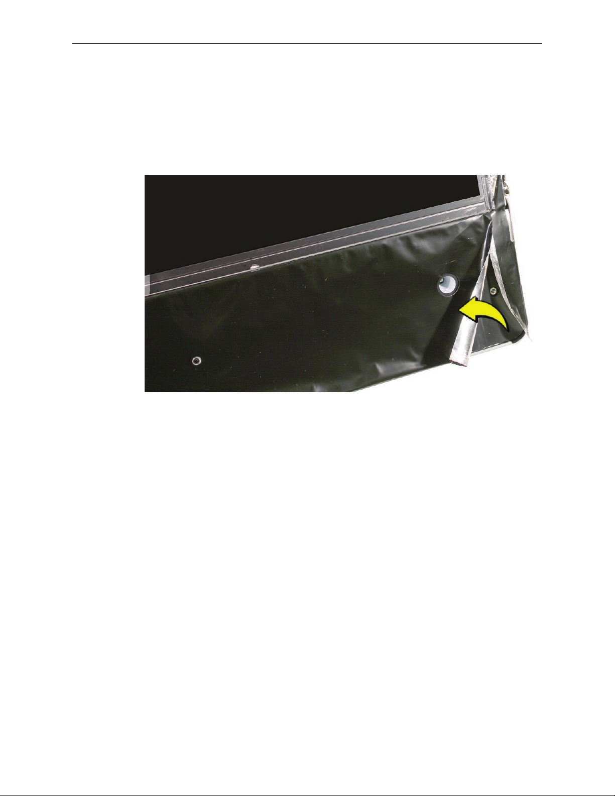
Remove the Lower EMI Shield
Carefully peel the lower EMI shield o the bottom edge of the rear housing. Use a black stick
1.
to help peel back the shield.
If replacing a torn or damaged lower EMI shield, peel the lower EMI shield o the bottom
2.
edge of the display.
Replace the Lower EMI Shield
Position the lower EMI shield over the bottom of the unit so that the holes in the shield are
1.
properly aligned.
Press the sticky, top edge of the EMI shield onto the bottom side of the display panel. The
2.
crease in the EMI shield should align with the edge of the panel.
Fold down the EMI shield and press it rmly over the bottom edge of the rear housing. Use a
3.
black stick to rub out wrinkles and ensure that the EMI shield adheres rmly along all edges.
Replace the front bezel.
4.
Replace the access door.
5.
iMac G5 (17-inch iSight) Take Apart — Lower EMI Shield — 29
IR Board
Tools
The only tool required for this procedure is a Torx T6 screwdriver (magnetized).
Preliminary Steps
Before you begin, follow steps for removing the following:
Access door
•
Front bezel
•
Lower EMI shield
•
Part Location
iMac G5 (17-inch iSight) Take Apart — IR Board 30

Remove the IR Board
Disconnect the IR cable from the IR board connector.
1.
Using a Torx T6 screwdriver, remove the two IR board mounting screws. Remove the IR board
2.
from its mounting bracket.
Replace the IR Board
Install the IR board and two mounting screws onto its mounting bracket.
1.
Connect the IR cable to the IR board connector.
2.
Replace the lower EMI shield.
3.
Replace the front bezel.
4.
Replace the access door.
5.
iMac G5 (17-inch iSight) Take Apart — IR Board 31

LCD Display
Tools
Removing the LCD display requires using the following tools:
Torx T10 screwdriver (magnetized)
•
Torx T6 screwdriver (magnetized)
•
Black stick (or other nonconductive nylon or plastic at-blade tool)
•
Preliminary Steps
Before you begin, follow steps for removing the following:
Access door
•
Front bezel
•
Lower EMI shield
•
Part Location
iMac G5 (17-inch iSight) Take Apart — Display Panel-32

Remove the LCD Display
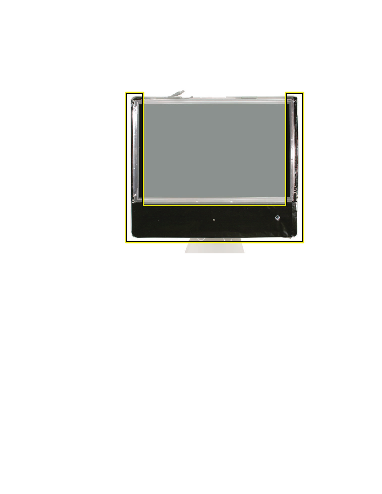
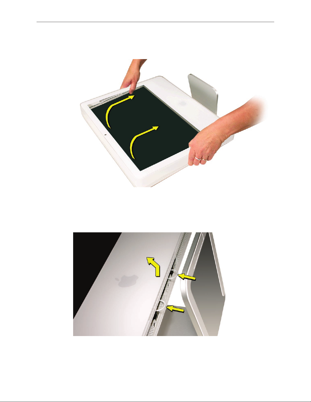
Using the black stick, carefully peel back the black, EMI shielding tape from the left and right
1.
top edges of the display panel.
Disconnect the inverter cable from the connector on the logic board.
2.
Using a Torx T6 screwdriver, remove the two TMDS connector mounting screws. Disconnect
3.
the TMDS cable from the logic board.
iMac G5 (17-inch iSight) Take Apart — Display Panel-33

Using a Torx T10 screwdriver, remove the four panel mounting screws.
4.
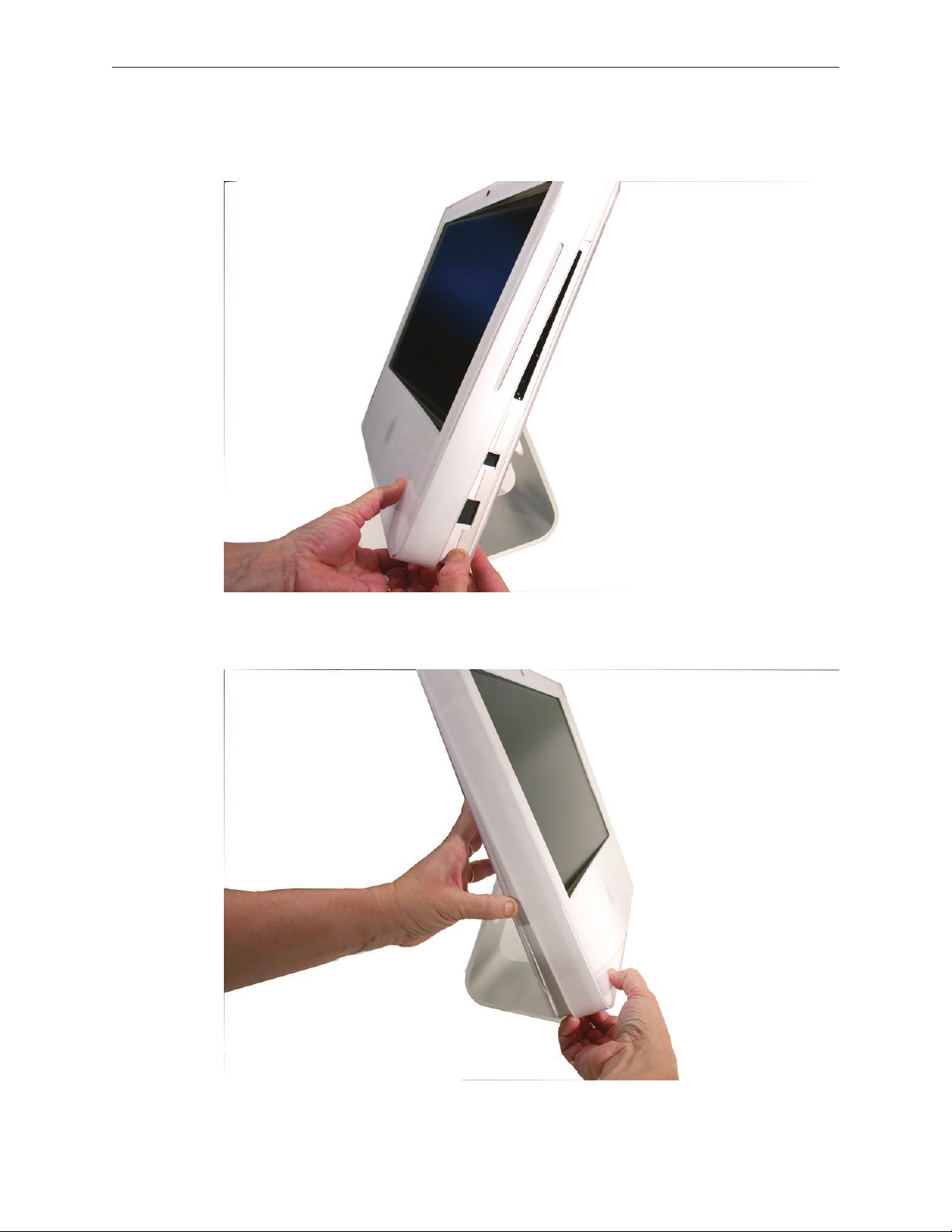
To remove the display panel, grasp it securely with both hands and pivot it completely over,
5.
as shown, then carefully peel the top edge of the panel away from the EMI skirt.
iMac G5 (17-inch iSight) Take Apart — Display Panel-34

Note: If replacing a bad LCD display, you will also need to remove the lower EMI shield
(if still attached), the display panel mounting brackets, and the TMDS cable as follows.
If attached, peel the lower EMI shield o the bottom edge of the display panel. 6.
iMac G5 (17-inch iSight) Take Apart — Display Panel-35

7.
Using a torx T8 screwdriver, remove two screws from the left side panel mounting bracket.
8.
Using a torx T8 screwdriver, push the tape aside and remove the two mounting screws from
the right side panel bracket as shown below.
iMac G5 (17-inch iSight) Take Apart — Display Panel-36

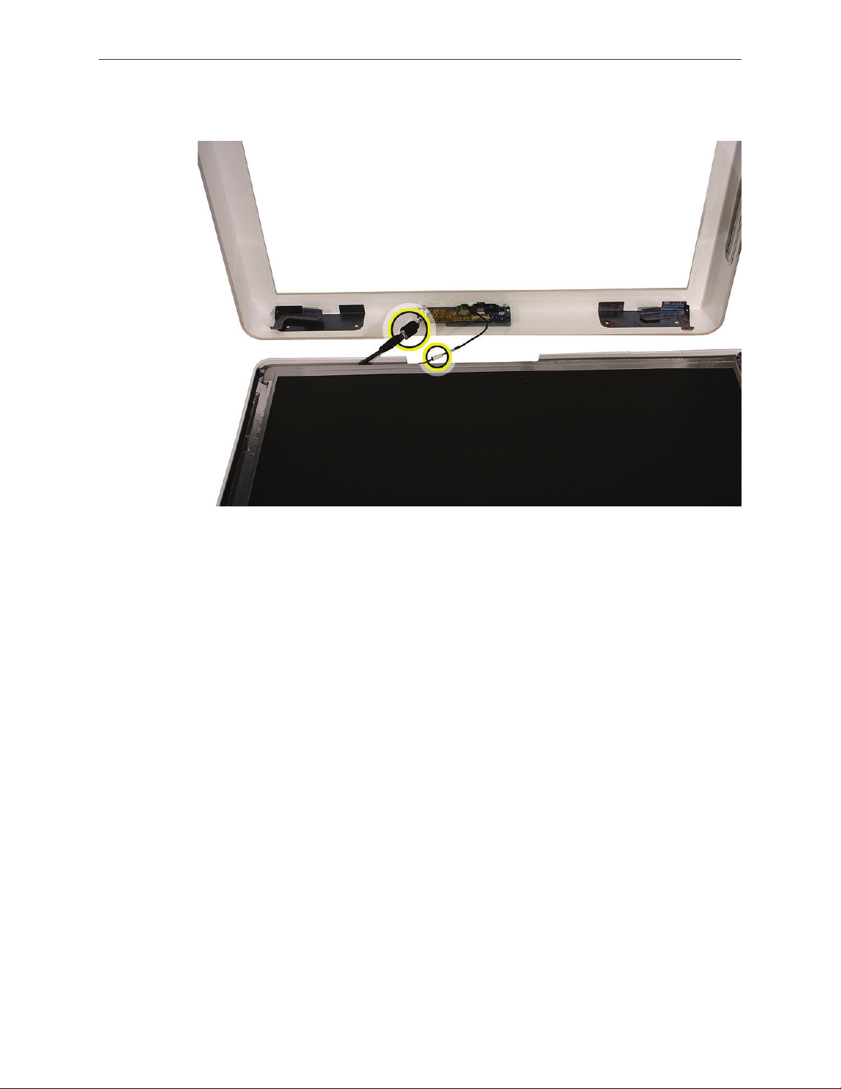
Peel back the tape where shown below, and disconnect the two inverter-to-display cable
9.
connectors.
Remove the TMDS cable from the rear of the display.
10.
Replace the LCD Display
If necessary, replace the TMDS cable on the rear of the display panel.
1.
If necessary, connect the two inverter-to-display cable connectors and tape them to the back
2.
of the display panel.
If necessary, replace the right panel mounting bracket on the display panel with two screws.
3.
If necessary, replace the left bracket on the display panel with two screws.
4.
iMac G5 (17-inch iSight) Take Apart — Display Panel-37

Push aside any cables that could interfere with the display mounting brackets when lowered
5.
into position.
Make sure the inverter cable extends beyond the bottom of the display panel, and install the
6.
panel with the mounting bracket screw holes and the screw mounts aligned.
Secure the panel with four mounting screws.
7.
Connect the inverter cable connector.
8.
Connect the TMDS cable connector and secure it with two screws.
9.
Fold the EMI tape rmly over the left, top, and right edges of the display panel. Use the black
10.
stick to adhere the tape rmly and rub out wrinkles.
Replace the lower EMI shield.
11.
Replace the front bezel.
12.
Replace the access door.
13.
iMac G5 (17-inch iSight) Take Apart — Display Panel-38

TMDS Cable
Tools
Removing the TMDS cable requires using the following tools:
Torx T8 screwdriver (magnetized)
•
Preliminary Steps
Before you begin, follow steps for removing the following:
Access door
•
Front bezel
•
Lower EMI shield
•
LCD Display
•
Part Location
iMac G5 (17-inch iSight) Take Apart — TMDS Cable 39

Remove the TMDS Cable
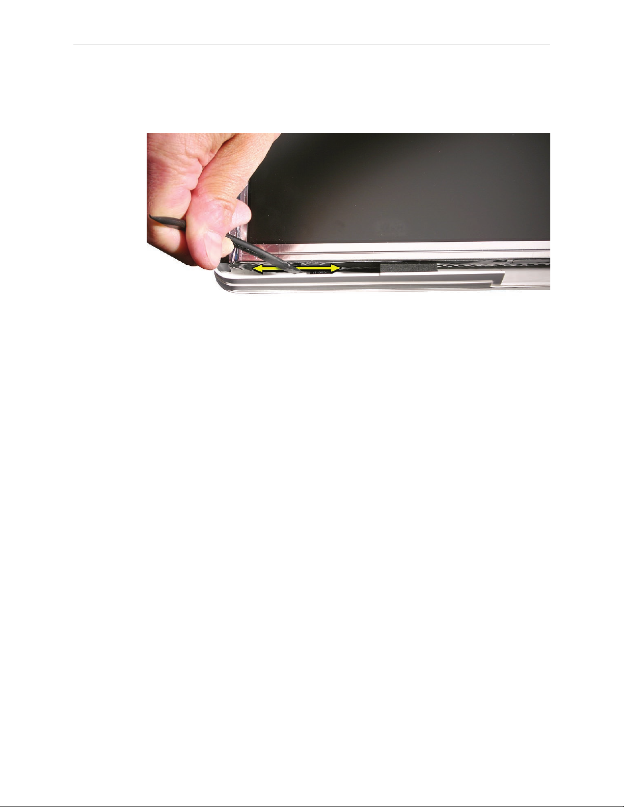
Locate the TMDS cable on the back side of the display panel, and remove the four pieces of
1.
tape that secure the cable to the panel.
iMac G5 (17-inch iSight) Take Apart — TMDS Cable 40

Pinch together the connector locking levers, and disconnect the TMDS cable connector.
2.
Replace the TMDS Cable
Position the TMDS cable on the back of the display panel as shown in the Part Location
1.
photo above.
Connect the TMDS cable connector. When connected correctly the locking levers will secure
2.
the connector and it cannot be disconnected without depressing the levers.
Secure the TMDS cable to the panel with four strips of tape.
3.
Replace the display panel.
4.
Replace the lower EMI shield.
5.
Replace the front bezel.
6.
Replace the access door.
7.
iMac G5 (17-inch iSight) Take Apart — TMDS Cable 41

Inverter
Tools
Removing the inverter requires using a at-blade screwdriver
Preliminary Steps
Before you begin, follow steps for removing the following:
Access door
•
Front bezel
•
Lower EMI shield
•
LCD Display
•
iMac G5 (17-inch iSight) Take Apart — Inverter42

Remove the Inverter
Remove two pieces of tape that secure the inverter cables to the back of the display panel,
1.
and disconnect the inverter connectors where shown.
2.
iMac G5 (17-inch iSight) Take Apart — Inverter43

Using a at-blade screwdriver as shown, pry up the inverter to remove it from inside the
3.
right side display panel mounting bracket.
Remove the inverter cable from the hole in the right mounting bracket to separate the
4.
inverter and bracket.
iMac G5 (17-inch iSight) Take Apart — Inverter44

Replace the Inverter
Insert the inverter cable through a hole at the back center of the right mounting bracket,
1.
and press the sticky side of the replacement inverter onto the back edge of the bracket.
Inverter should look as shown below.
Connect the inverter-to-display cables and tape them to the back of the display panel.
2.
Replace the display panel.
3.
Replace the lower EMI shield.
4.
Replace the front bezel.
5.
Replace the access door.
6.
iMac G5 (17-inch iSight) Take Apart — Inverter45

Speakers
Tools
Removing the speaker requires using the following tools:
Torx T10 screwdriver (magnetized)
•
Torx T6 screwdriver (magnetized)
•
Preliminary Steps
Before you begin, follow steps for removing the following:
Access door
•
Front bezel
•
Lower EMI shield
•
LCD Display
•
Part Location
iMac G5 (17-inch iSight) Take Apart — Speaker

Remove the Speakers
Using a T10 torx screwdriver, remove the mounting screws from the left and right speakers.
1.
Replacement Note: The longer of the two speaker mounting screws is used to secure the
left speaker; the shorter screw secures the right speaker.
Using a T6 torx screwdriver, remove the screw that secures the IR board mounting bracket to
2.
the logic board. Remove the IR mounting bracket and attached gold bracket.
iMac G5 (17-inch iSight) Take Apart — Speaker

Lift the left speaker straight up to remove it.
3.
Replacement Note: Note the location and positioning of the speaker cable for reinstallation
later.
Lift the right speaker straight up and disconnect the speaker cable connector from the logic
4.
board.
Replace the Speakers
Install the speakers and route the speaker wire as shown below.
1.
Connect the speaker cable connector to the logic board,
2.
Secure the right speaker with the smaller of the two mounting screws.
3.
Secure the left speaker with the longer of the two mounting screws.
4.
Install the IR board mounting bracket, gold bracket, and screw.
5.
Replace the display panel.
6.
Replace the EMI shield.
7.
Replace the front bezel.
8.
Replace the access door.
9.
iMac G5 (17-inch iSight) Take Apart — Speaker

CPU Fan
Tools
No tools are required to remove the CPU fan.
Preliminary Steps
Before you begin, follow steps for removing the following:
Access door
•
Front bezel
•
Lower EMI shield
•
LCD Display
•
Speakers
•
Part Location
iMac G5 (17-inch iSight) Take Apart — CPU Fan

Remove the CPU Fan
Disconnect the CPU fan cable from the logic board.
1.
Lif the CPU fan straight up to remove it from three mounting posts.
2.
Replace the CPU Fan
Align the CPU fan with the three mounting posts in the rear housing, and push it straight
1.
down onto the posts.
Connect the CPU fan cable to the logic board connector.
2.
Replace the speakers.
3.
Replace the display panel.
4.
Replace the lower EMI shield.
5.
Replace the front bezel.
6.
Replace the access door.
7.
iMac G5 (17-inch iSight) Take Apart — CPU Fan

Optical Drive
Tools
Removing the optical drive requires using the following tools:
Torx T10 screwdriver (magnetized)
•
Torx T6 screwdriver (magnetized)
•
Flat-blade screwdriver
•
Preliminary Steps
Before you begin, follow steps for removing the following:
Access door
•
Front bezel
•
Lower EMI shield
•
LCD Display
•
Part Location
iMac G5 (17-inch iSight) Take Apart — Optical Drive 51

Remove the Optical Drive
Disconnect the sensor cable from the temperature sensor on top of the optical drive.
1.
Using a T10 torx screwdriver, remove the screw and ex cable mounting bracket. Disconnect
2.
the optical drive ex cable from the logic board connector.
iMac G5 (17-inch iSight) Take Apart — Optical Drive 52

Locate the release levers at each side of the black, plastic drive mounting bracket. Using a
3.
at-blade screwdriver as shown. press down on the mounting bracket at the base of the
release lever, while pinching the release lever toward the center of the drive. Repeat process
to unhook the other release lever.
Caution: Never press down on or grasp the body (silver) of the optical drive when removing
or installing it. Depressing the body of the optical drive could damage the mechanism. Grasp
the optical drive by its mounting bracket only.
Lift the rear of the drive and pull the front bezel of the drive straight back and out of the
4.
access hole in the housing.
iMac G5 (17-inch iSight) Take Apart — Optical Drive 53

If replacing a bad optical drive, use a T6 torx screwdriver to remove two ex cable mounting
5.
screws. Disconnect and keep the ex cable for installation on the replacement drive.
If replacing a bad optical drive, also remove the temperature sensor from the top of the
6.
drive. Discard the sensor—the replacement drive comes with a new sensor already installed.
iMac G5 (17-inch iSight) Take Apart — Optical Drive 54

Replace the Optical Drive
If necessary, install the ex cable to the optical drive with two screws.
1.
Insert the optical drive bezel-end-rst into the access hole in the housing. Be sure to align
2.
the two guide holes in the front bezel with guide posts at each end of the drive access hole.
iMac G5 (17-inch iSight) Take Apart — Optical Drive 55

Push down on the mounting bracket to lock the optical drive securely into place on the
3.
chassis.
Caution: Never press down on or grasp the body (silver) of the optical drive when removing
or installing it. Depressing the body of the optical drive could damage the mechanism. Grasp
the optical drive by its mounting bracket only.
Connect the optical drive ex cable and secure it with the ex cable mounting clip and
4.
screw.
Replace the display panel.
5.
Replace the lower EMI shield.
6.
Replace the front bezel.
7.
Replace the access door.
8.
iMac G5 (17-inch iSight) Take Apart — Optical Drive 56

iMac G5 (17-inch iSight) Take Apart — Optical Drive 57

Hard Drive
Tools
Removing the hard drive requires using the following tools:
Torx T8 screwdriver (magnetized)
•
Flat-blade screwdriver
•
Preliminary Steps
Before you begin, follow steps for removing the following:
Access door
•
Front bezel
•
Lower EMI shield
•
LCD Display
•
Part Location
iMac G5 (17-inch iSight) Take Apart — Hard Drive 58

Remove the Hard Drive
Disconnect the sensor cable from the temperature sensor on top of the hard drive.
1.
Remove the temperature sensor from the drive. Transfer the sensor to the replacement hard
2.
drive.
iMac G5 (17-inch iSight) Take Apart — Hard Drive 59

Position yourself at the top side of the unit closest to the hard drive mounting bracket.
3.
Grasp the mounting bracket as shown, and push in and down on the edge of the bracket
4.
until you feel it release. If the bracket doesn’t release, use your left hand to hold it in this
depressed position, and with your right hand use a at-blade screwdriver to pry up on the
bottom of the mounting bracket to help release it.
iMac G5 (17-inch iSight) Take Apart — Hard Drive 60

Disconnect the hard drive power and data cables.
5.
Note: If you are replacing a defective hard drive continue with the procedure to transfer the
6.
temperature sensor, mounting bracket, and mounting pins to the replacement drive.
iMac G5 (17-inch iSight) Take Apart — Hard Drive 61

Using a T8 torx screwdriver, remove two screws and the mounting bracket from the drive.
7.
Using a T8 torx screwdriver, remove two mounting pins from the other side of the drive.
8.
iMac G5 (17-inch iSight) Take Apart — Hard Drive 62

Replace the Hard Drive
Install two mounting pins in the bottom side of the hard drive mounting bracket.
1.
Install the mounting bracket to the top of the hard drive with two screws.
2.
Install the temperature senor on the hard drive. Use the double-stick tape enclosed with the
3.
replacement hard drive to attach the sensor.
Connect the hard drive power and data cables.
4.
Insert the hard drive mounting pins and position the drive on the chassis. Make sure the
5.
hard drive power and data cables are routed around the drive and beneath the hard drive
mounting bracket. Press down on the mounting bracket to lock it in place on the chassis.
Connect the sensor cable to the temperature sensor on top of the hard drive.
6.
Replace the display panel.
7.
Replace the lower EMI shield.
8.
Replace the front bezel.
9.
Replace the access door.
10.
iMac G5 (17-inch iSight) Take Apart — Hard Drive 63

DC-DC Board
Tools
Removing the optical drive requires using the following tools:
Torx T10 screwdriver (magnetized)
•
Preliminary Steps
Before you begin, follow steps for removing the following:
Access door
•
Front bezel
•
Lower EMI shield
•
LCD Display
•
Part Location
iMac G5 (17-inch iSight) Take Apart — DC-DC Board

Remove the DC-DC Board
Disconnect the power supply cable and the DC power cable from the DC-DC board. 1.
iMac G5 (17-inch iSight) Take Apart — DC-DC Board

Using a T10 torx screwdriver, remove the two self-tapping screws from the bottom corners of
2.
the DC-DC board. The lower left mounting screw is beneath the power supply cable.
Using a T10 torx screwdriver, remove the machine screw from the upper right corner of the
3.
board. Lift the board straight up to remove it.
Replace the DC-DC Board
Position the DC-DC board and install the machine screw in upper right corner
1.
Install the long black self-tapping screw in the lower right corner, and the medium-length,
2.
silver self-tapping screw in the lower left corner.
Connect the DC power cable and the power supply cable to connectors on the DC-DC board.
3.
Replace the display panel.
4.
Replace the lower EMI shield.
5.
Replace the front bezel.
6.
Replace the memory access door.
7.
iMac G5 (17-inch iSight) Take Apart — DC-DC Board

Power Supply
Tools
Removing the optical drive requires using the following tools:
Torx T10 screwdriver (magnetized)
•
Preliminary Steps
Before you begin, follow steps for removing the following:
Access door
•
Front bezel
•
Lower EMI shield
•
LCD Display
•
Hard drive
•
Part Location
iMac G5 (17-inch iSight) Take Apart — Power Supply

About the Power Supply
Warning: When the iMac G5 (iSight) is under power, be aware that the power supply contains
high voltages that pose a potential hazard to your personal safety. Never work on or near the
power supply with the unit powered on, and as a further precaution always make sure the unit is
unplugged when working on it with the front bezel removed.
WARNING: HIGH VOLTAGE
Text or photographs marked by this symbol indicate that a potential hazard to your personal
safety exists from a high voltage source.
The AC/DC power supply board is a high voltage source with the unit under power, and remains
powered up whenever the system is plugged in, whether or not the system is turned on. Use
extreme caution when troubleshooting the system with the front bezel removed.
Disconnect power to the system before performing maintenenace.
•
Don’t work alone. In the even of an electrical shock it is important to have another
•
individual present who can provide assistance.
Keep one hand in your pocket when working on any iMac G5 (iSight) that is plugged in.
•
This will help ensure that your body does not provide a path to ground in the event that
you accidentally make contact with the line voltage.
Don’t wear jewelry, watches, necklaces, or other metallic articles that could present a risk
•
if they accidentally make contact with the power supply circuitry.
iMac G5 (17-inch iSight) Take Apart — Power Supply

Remove the Power Supply
Using a T10 torx screwdriver, remove the three self-tapping screws from both top corners
1.
and the lower left corner of the DC-DC board. Then remove the machine screw from the
lower right corner of the board.
Replacement Note: When installing the mounting screws in the power supply, install the
machine screw rst in the lower right corner of the power supply. Then install the three self-
tapping screws.
iMac G5 (17-inch iSight) Take Apart — Power Supply

Disconnect the power supply cable.
2.
Pull out the power supply-to-TMDS cable from beneath the chassis. Disconnect the
3.
connectors.
Replace the Power Supply
Postion the power supply loosely in its mounting location.
1.
Route the power supply end of the power supply-to-TMDS cable beneath the chassis. Pull
2.
out the TMDS end of the power supply-to-TMDS cable and connect the two connectors. Tuck
the cable beneath the chassis and away from the hard drive bay.
Connect the DC power cable.
3.
Install the machine screw in the lower right corner of the power supply.Then install the three
4.
self-tapping screws.
Replace the hard drive.
5.
Replace the display panel.
6.
Replace the lower EMI shield.
7.
Replace the front bezel.
8.
Replace the memory access door.
9.
iMac G5 (17-inch iSight) Take Apart — Power Supply

Logic Board
Tools
Removing the optical drive requires using the following tools:
Torx T10 screwdriver (magnetized)
•
Torx T6 screwdriver (magnetized)
•
Preliminary Steps
Before you begin, follow steps for removing the following:
Access door
•
Front bezel
•
Lower EMI shield
•
IR Board
•
LCD Display
•
Speakers
•
CPU Fan
•
Part Location
iMac G5 (17-inch iSight) Take Apart — Logic Board 71

Remove the Logic Board
Using a T10 torx screwdriver, remove the screw and ex cable mounting bracket. Disconnect
1.
the optical drive ex cable from the logic board connector
Disconnect the large, hard drive data cable from the center of the logic board.
2.
iMac G5 (17-inch iSight) Take Apart — Logic Board 72

Disconnect the following cables from connectors on the logic board. Connectors are shown
3.
starting in the lower left corner, proceeding clockwise.
Ambient light sensor
Power on
Hard drive temperature sensor (Temp 1)
Optical drive temperature sensor (Temp 2)
Hard drive fan
Optical drive fan
Camera board
iMac G5 (17-inch iSight) Take Apart — Logic Board 73

Using a T6 torx screwdriver, remove two screws and disconnect the AirPort-Bluetooth combo
4.
card. Also disconnect the AirPort and Bluetooth cables from the card.
iMac G5 (17-inch iSight) Take Apart — Logic Board 74

Remove the seven remaining logic board mounting screws. First remove the three self-
5.
tapping screws circled below, and then remove the four machine screws, shown with
double-yellow circles below.
Lift the logic board just enough to access the power supply cable connector on the
6.
underside of the logic board. Disconnect the cable and remove the logic board.
iMac G5 (17-inch iSight) Take Apart — Logic Board 75

Replace the Logic Board
Connect the power supply cable to the connector on the bottom of the logic boardCon.
1.
Pull all cables up and away from the logic board bay and gently place down the logic board
2.
so that all screw holes are aligned with screw mounts in the chassis.
Replacement Note: The logic board should rest on the screw mounts without any binding
or bowing—if it doesn’t, adjust any cables that are interfering with the logic board.
Before securing the logic board, connect the camera board cable to its connector on the
3.
right side of the logic board.
Secure the logic board by installing four machine screws, and then installing three self-
4.
tapping screws.
Connect the AirPort and Bluetooth cables to connectors on the combo card.
5.
Note that the cables can be connected to either connector on the combo card.
Connect the combo card and install two mounting screws.
6.
Connect seven cables to connectors on the logic board as indicated in the removal step
7.
above.
Connect the optical drive ex cable and secure it with the ex cable mounting clip and
8.
screw.
Replace the CPU fan.
9.
Replace the speakers.
10.
Replace the display panel.
11.
Replace the IR Board.
12.
Replace the lower EMI shield.
13.
Replace the front bezel.
14.
Replace the memory access door.
15.
iMac G5 (17-inch iSight) Take Apart — Logic Board 76

Optical Drive Fan
Tools
No tools are required to remove the optical drive fan.
Preliminary Steps
Before you begin, follow steps for removing the following:
Access door
•
Front bezel
•
Lower EMI shield
•
IR Board
•
LCD Display
•
Speakers
•
CPU Fan
•
Logic Board
•
Part Location
iMac G5 (17-inch iSight) Take Apart — Optical Drive Fan 77

Remove the Optical Drive Fan
Lift the optical drive fan straight up and o three mounting posts.
1.
Replace the Optical Drive Fan
Make sure the hard drive power cable and camera board cable are routed beneath the
1.
optical drive fan as shown above. Align and install the optical drive fan on three mounting
posts. Push it down snug onto the posts.
Replace the logic board.
2.
Replace the CPU fan.
3.
Replace the speakers.
4.
Replace the display panel.
5.
Replace the IR Board.
6.
Replace the lower EMI shield.
7.
Replace the front bezel.
8.
Replace the memory access door.
9.
iMac G5 (17-inch iSight) Take Apart — Optical Drive Fan 78

Hard Drive Fan
Tools
No tools are required to remove the optical drive fan.
Preliminary Steps
Before you begin, follow steps for removing the following:
Access door
•
Front bezel
•
Lower EMI shield
•
IR Board
•
LCD Display
•
Speakers
•
CPU Fan
•
Logic board
•
Part Location
iMac G5 (17-inch iSight) Take Apart — Hard Drive Fan 79

Remove the Hard Drive Fan
Lift the hard drive fan straight up and o three mounting posts.
1.
Replace the Hard Drive Fan
Make sure the hard drive fan cable is routed up toward the hard drive and beneath the
1.
mounting bracket of the fan. Align and install the hard drive fan on three mounting posts.
Push it down snug onto the posts.
Replace the logic board.
2.
Replace the CPU fan.
3.
Replace the speakers.
4.
Replace the display panel.
5.
Replace the IR Board.
6.
Replace the lower EMI shield.
7.
Replace the front bezel.
8.
Replace the memory access door.
9.
iMac G5 (17-inch iSight) Take Apart — Hard Drive Fan 80

AC Power Inlet
Tools
Removing the AC power inlet requires using the following tools:
Torx T10 screwdriver (magnetized)
•
Preliminary Steps
Before you begin, follow steps for removing the following:
Access door
•
Front bezel
•
Lower EMI shield
•
IR Board
•
LCD Display
•
Speakers
•
CPU Fan
•
Logic board
•
Hard drive fan
•
Part Location
iMac G5 (17-inch iSight) Take Apart — AC Power Inlet 81

Remove the AC Power Inlet
Using a torx T10 screwdriver, remove the three self-tapping screws from the power inlet.
1.
Using a tox T10 screwdriver, remove the machine screw from the power inlet ground cable.
2.
iMac G5 (17-inch iSight) Take Apart — AC Power Inlet 82

Disconnect the power inlet-to-power supply cables and unlace the power inlet cable from
3.
beneath the chassis.
Peel up the EMI tape that secures the AC power inlet to the rear housing and remove the
4.
power inlet.
iMac G5 (17-inch iSight) Take Apart — AC Power Inlet 83

Replace the AC Power Inlet
Install the AC power inlet on the rear housing screw mounts with three self tapping screws.
1.
Install the power inlet ground cable to the chassis with a machine screw.
2.
Route the power inlet cable beneath the chassis as shown in the photo above, and connect
3.
it to the power supply.
Using EMI tape, securely tape the top and bottom edges of the AC power inlet to the rear
4.
housing.
Replace the hard drive fan.
5.
Replace the logic board.
6.
Replace the CPU fan.
7.
Replace the speakers.
8.
Replace the display panel.
9.
Replace the IR Board.
10.
Replace the lower EMI shield.
11.
Replace the front bezel.
12.
Replace the memory access door.
13.
iMac G5 (17-inch iSight) Take Apart — AC Power Inlet 84

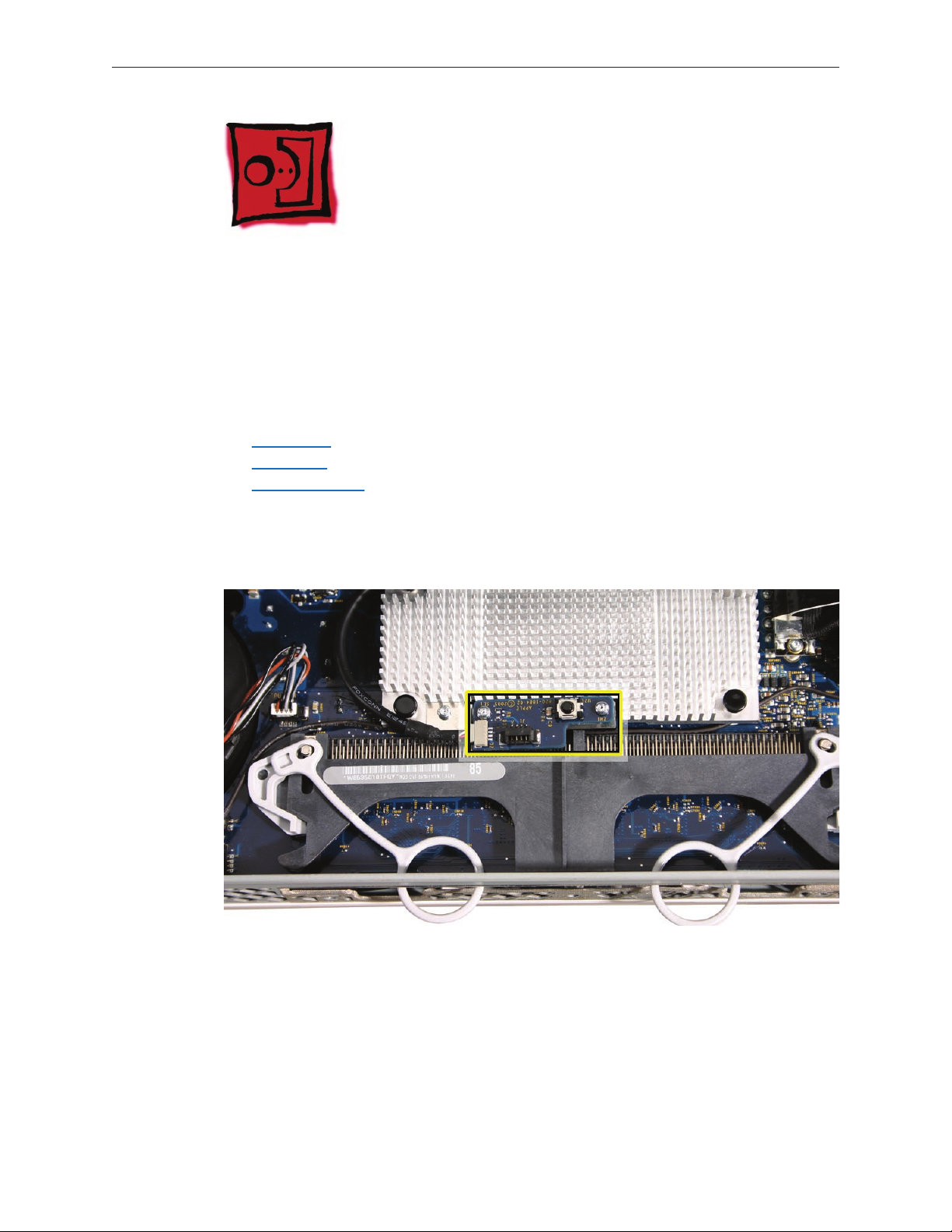
Ambient Light Sensor Board
Tools
No tools are required to remove the ambient light sensor board.
Preliminary Steps
Before you begin, follow steps for removing the following:
Access door
•
Front bezel
•
Lower EMI shield
•
IR Board
•
LCD Display
•
Speakers
•
CPU Fan
•
Logic board
•
Part Location
iMac G5 (17-inch iSight) Take Apart — ALS Board 85

Remove the Ambient Light Sensor Board
Remove the rubber bumper from between the chassis and the ALS board.
1.
Peel the ALS o the inside bottom of the rear housing.
2.
Replace the Ambient Light Sensor Board
Press the sticky side of the ALS board to the bottom inside edge of the rear housing.
1.
Install the rubber bumper between the back of the ALS board and the chassis.
2.
Replace the logic board.
3.
Replace the CPU fan.
4.
Replace the speakers.
5.
Replace the display panel.
6.
Replace the IR Board.
7.
Replace the lower EMI shield.
8.
Replace the front bezel.
9.
Replace the memory access door.
10.
iMac G5 (17-inch iSight) Take Apart — ALS Board 86

iMac G5 (17-inch iSight) Take Apart — ALS Board 87

iMac G5 (17-inch iSight) Take Apart — ALS Board 88

Clutch
Tools
Removing the clutch requires using the following tools:
Torx T10 screwdriver (magnetized)
•
Preliminary Steps
Before you begin, follow steps for removing the following:
Access door
•
Front bezel
•
Lower EMI shield
•
IR Board
•
LCD Display
•
Speakers
•
CPU fan
•
Logic board
•
Optical drive fan
•
Hard drive fan
•
Hard drive
•
iMac G5 (17-inch iSight) Take Apart — Clutch 89

Part Location
iMac G5 (17-inch iSight) Take Apart — Clutch 90

Remove the Clutch
Carefully peel back the EMI tape and pull the cover straight o the clutch.
1.
Using a T10 torx screwdriver, remove the four clutch mounting screws.
2.
iMac G5 (17-inch iSight) Take Apart — Clutch 91

Stand up the unit, and peel up the silk tape to access the four clutch-to-stand mounting
3.
screws. .
Using a T10 torx screwdriver, remove the four clutch-to-stand screws. Remove the clutch and
4.
cover from the stand.
5.
iMac G5 (17-inch iSight) Take Apart — Clutch 92

Replace the Clutch
Make sure the stand is erect and the end of the stand is inserted through the mounting hole
1.
in the rear housing.
Position the clutch on the stand as shown, with the springs at bottom right. Install the four
2.
long, clutch-to-stand mounting screws..
Adjust the clutch so that its chassis mounting holes align, and install the four machine
3.
screws that secure the clutch to the chassis.
Replace the hard drive.
4.
Replace the hard drive fan.
5.
Replace the optical drive fan.
6.
Replace the logic board.
7.
Replace the CPU fan.
8.
Replace the speakers.
9.
Replace the display panel.
10.
Replace the IR Board.
11.
Replace the lower EMI shield.
12.
Replace the front bezel.
13.
Replace the memory access door.
14.
iMac G5 (17-inch iSight) Take Apart — Clutch 93

Wireless Antenna
Tools
Removing the wireless antenna requires using the following tools:
Flat-blade screwdriver
•
Black stick (or other nonconductive nylon or plastic at-blade tool)
•
Preliminary Steps
Before you begin, follow steps for removing the following:
Access door
•
Front bezel
•
Lower EMI shield
•
IR Board
•
LCD Display
•
Speakers
•
CPU fan
•
Logic board
•
Optical drive fan
•
Optical drive
•
iMac G5 (17-inch iSight) Take Apart — Wireless Antenna 94

Part Location
Remove the Wireless Antenna
Carefully peel back the EMI skirt and backing from the top right inside corner of the rear
1.
housing as shown below. Peel back just enough EMI backing to access the antenna cable.
iMac G5 (17-inch iSight) Take Apart — Wireless Antenna 95

Remove two pieces of tape that secure the antenna cable to the rear housing. Remove the
2.
connectors end of the antenna cable from the access hole in the EMI skirt.
Using a at-blade screwdriver, pry the antenna o the rear housing.
3.
iMac G5 (17-inch iSight) Take Apart — Wireless Antenna 96

Replace the Wireless Antenna
Locate the antenna mounting channel inside the top right corner of the rear housing, and
1.
position the antenna in the channel. Compress the sticky side of the antenna to the housing
until securely fastened.
Route the antenna cable as shown in the photo above, and insert the connectors end of the
2.
cable through the access hole in the EMI skirt. Leave about 2 inches of cable extending from
the skirt.
Secure the antenna cable to the housing with two pieces of tape.
3.
Carefully replace the EMI skirt and backing. Using a black stick, work out all wrinkles and
4.
bubbles until the EMI tape is smooth and tight.
Replace the optical drive.
5.
Replace the optical drive fan.
6.
Replace the logic board.
7.
Replace the CPU fan.
8.
Replace the speakers.
9.
Replace the display panel.
10.
Replace the IR Board.
11.
Replace the lower EMI shield.
12.
Replace the front bezel.
13.
Replace the memory access door.
14.
iMac G5 (17-inch iSight) Take Apart — Wireless Antenna 97

DC Power Cable
Tools
No tools are required to remove the DC power cable.
Preliminary Steps
Before you begin, follow steps for removing the following:
Access door
•
Front bezel
•
Lower EMI shield
•
IR Board
•
LCD Display
•
Speakers
•
CPU fan
•
Logic board
•
Optical drive fan
•
Optical drive
•
Hard Drive
•
iMac G5 (17-inch iSight) Take Apart — DC Power Cable 98

Part Location
Remove the DC Power Cable
Remove tape that secures the DC power cable to the rear housing, and remove the DC
1.
power cable.
iMac G5 (17-inch iSight) Take Apart — DC Power Cable 99

Replace the DC Power Cable
Route the DC power cable as shown above. Tape the DC power cable and the camera cable
1.
to the rear housing where shown below.
Replace the hard drive.
2.
Replace the optical drive.
3.
Replace the optical drive fan.
4.
Replace the logic board.
5.
Replace the CPU fan.
6.
Replace the speakers.
7.
Replace the display panel.
8.
Replace the IR Board.
9.
Replace the lower EMI shield.
10.
Replace the front bezel.
11.
Replace the memory access door.
12.
iMac G5 (17-inch iSight) Take Apart — DC Power Cable 100
 Loading...