

Page 1
K
Service Source
Apple Multiple Scan 20
Display
Apple Multiple Scan 20 Display
Apple Multiple Scan 20 Display, Rev. B
Page 2
K
Service Source
Basics
Apple Multiple Scan 20 Display
Page 3

Basics Version Differences - 2
Version Differences
Overview
The Apple Multiple Scan 20 Display and Apple Multiple Scan
20 Display Rev. B have the same overall appearance.
However, the Rev. B version offers improved performance
and better screen resolution.
To distinguish the two versions, check the last three digits of
the serial number. The serial number for the Rev. B version
ends in one of the following:
• 5B4
• 5J2
• 5JE
• 5JF
Page 4

Basics Version Differences - 3
Multiple Scan 20 Display
Dot pitch 0.31 mm.
Multiple Scan 20 Display, Rev. B
Dot pitch 0.26 mm.
Requires Rev. B parts for Main Deflection Board,
Microprocessor Controller Board, and Power Supply.
As you go through this manual, consider the information
applicable to both versions unless specified otherwise.
Page 5

Basics Monitor Distortion - 4
Monitor Distortion
Overview
All large-screen monitors are susceptible to distortions
caused by environmental conditions. These distortions are
usually not visible on monitors with smaller screens.
Important:
appear distorted when set up in a new environment.
Common environmentally caused distortions are shown on
this and the following cards. Always check first for
environmental causes before attempting to exchange or
adjust a monitor with a distorted raster.
Ê
Even monitors set to factory specifications may
Page 6
Basics Monitor Distortion - 5
Ideal Raster
Raster Shifted Up
and Left
Raster Shifted Up
and Right
Page 7

Basics Monitor Distortion - 6
Environmental Influences
The following environmental conditions may distort the
raster:
• Proximity to metal objects, such as metal desks, file
cabinets, and bookshelves. Metal objects affect the
earth’s magnetic field. Earth magnetism usually distorts
only the edges of the screen.
• Fluorescent lights, other monitors, or electronic
appliances such as coffee makers and copy machines.
These objects cause dynamic raster distortion, that is,
movement or jitter of the image.
Page 8
Basics - 7
Right Edge Not Straight
Left Side Bowed Out Right Side Bowed In
Page 9

Basics - 8
Troubleshooting
Important:
environmental distortion problems.
Note:
go ahead and adjust it using the user controls. However, keep
in mind that if you then move the monitor you may need to
readjust the centering controls.
Before adjusting a monitor with a distorted raster, try the
following:
• Swivel or move the monitor, or
• Remove the monitor from the building and recheck it in
another location.
Exchanging the monitor cannot correct
If the monitor has shifted up/down or right/left only,
Page 10

Basics - 9
If the display changes (for better or worse) when you move
it to another location, the environment is the source of the
problem. Relocate your monitor or remove the distortioncausing object.
If the display does not change when you move it to another
location, continue troubleshooting the problem (refer to
Troubleshooting).
Page 11
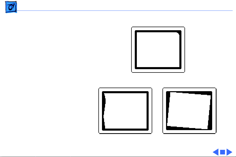
Basics - 10
Upper-Right Corner Rounded
Left Edge S-Shaped Raster Tilted Right
Page 12

Basics EEPROM Settings - 11
EEPROM Settings
Caution:
EEPROM settings before you replace the microprocessor
board.
See Troubleshooting for instructions on saving the EEPROM
settings from the old microprocessor board and restoring
the settings on the new microprocessor board.
If the settings are lost before they can be written to the new
EEPROM, the display will be impossible to repair, and the
whole display will need to be replaced.
To prevent data loss or corruption, always save
Page 13
Basics EEPROM Settings - 12
Microprocessor Board
Page 14
K
Service Source
Specifications
Apple Multiple Scan 20 Display
Page 15

Specifications Characteristics - 1
Characteristics
Picture Tube
Screen Resolution
Scan Rates
Cable Connector
20-in. diagonal Trinitron CRT (19.1-in. viewable image)
Multiple scan
Bonded glass panel with antiglare/antistatic multilayer coating
640x480 to 1280x1024
0.31-mm stripe pitch
0.26-mm stripe pitch for Multiple Scan 20 Display, Rev. B
Vertical refresh range: 50 to 150 Hz
Horizontal scan range: 29 to 82 kHz
Macintosh, VGA, SVGA, and VESA compatible
15-pin miniature D-type
Page 16

Specifications Characteristics - 2
Video Input Signals
System Requirements
Video: red, green, and blue analog signals; RS-343A
standard;.714 V peak to peak; positive going
Sync on green: RS-343A compatible level;.286 V ± 10%
negative-going during blanking intervals
Separate Sync: 1 to 5 V peak to peak; negative or positive going
Composite Sync: 1 to 5 V peak to peak; negative or positive going
Power Macintosh, Macintosh Centris, Macintosh Quadra, or any
NuBus compatible Macintosh with a Macintosh Display Card
24AC.
Macintosh II family, PowerBooks, Duo and Mini Dock, Macintosh
Performa, Macintosh LC, LC II, LC III, and Macintosh
computers with Display Cards 4•8, 8•24, 8•24GC work in
640x480 mode. Other modes possible with additional adapters.
System software version 7.1 or later
Page 17

Specifications Controls and Ports - 3
Controls and Ports
User Controls
I/O Ports
Front panel: power, reset, and control buttons; brightness and
contrast controls
Additional controls available using the command button: horizontal
and vertical shift, horizontal and vertical size, rotation,
horizontal and vertical convergence, and color temperature
Automatic degauss at power on; manual degauss by turning power
switch off, then on (capable of full degauss after monitor is
turned off for 20 minutes or more)
Two Apple Desktop Bus (ADB) ports and one ADB pass-through
port
Page 18

Specifications Physical and Electrical - 4
Physical and Electrical
Power Supply
Size and Weight
Universal power supply
Voltage: 90–132 and 198–264 VAC, self-configuring
Frequency: 47–63 Hz
Power: 165 W maximum (less than 15 W in energy-saver mode)
Height: 18.5 in. (474 mm)
Width: 18.5 in. (474 mm)
Depth: 19.6 in. (501.5 mm)
Monitor weight: 66 lb. (30 kg)
Fully boxed weight: 80 lb. (36 kg)
Page 19

Specifications Physical and Electrical - 5
Monitor Stand
Built-in, tilt-and-swivel stand; tilt: -5 to +15°; swivel range:
±45° minimum
Three ADB ports (two ADB ports are in the front of the stand and
one ADB port is at the rear of the stand)
Page 20

Specifications Environmental - 6
Environmental
Temperature
Altitude
Humidity
Power Savings Feature
Operating: 50°F to 104°F (10°C to 40°C)
Storage: 32°F to 140°F (0°C to 60°C)
Shipping: -4°F to 140°F (-40°C to 60°C)
Operating: to 10,000 ft. (1,067 m)
Shipping: to 35,000 ft. (3,048 m)
Operating: 10-80% maximum, noncondensing
Storage: 5-90% maximum, noncondensing
Shipping: 5-95% maximum, noncondensing
Conforms to the Energy Star Program of the United States
Environmental Protection Agency
Page 21

K
Service Source
Troubleshooting
Apple Multiple Scan 20 Display
Page 22

Troubleshooting General - 1
General
The Symptom Charts included in this chapter will help you
diagnose specific symptoms related to your product. Because cures
are listed on the charts in the order of most likely solution, try
the first cure first. Verify whether or not the product continues to
exhibit the symptom. If the symptom persists, try the next cure.
(Note: If you have replaced a module, reinstall the original module
before you proceed to the next cure.)
If you are not sure what the problem is, or if the Symptom Charts
do not resolve the problem, refer to the Flowchart for the product
family.
For additional assistance, contact Apple Technical Support.
Page 23

Troubleshooting First Checklist - 2
First Checklist
Important:
modules returned for repair are found to be fully operational.
Read this checklist before you return a module. Prevent needless
module replacement and unnecessary time delays.
Over 60% of the Apple Multiple Scan 20 Display
The Apple Multiple Scan 20 Display is not fully
compatible with all Macintosh computers and
PowerBooks.
If you suspect a loss of functionality, especially with the number
of screen resolutions available (in Control Panels), check the
Tech Info Library or contact Apple Technical Support.
Page 24
Troubleshooting First Checklist - 3
The CRT raster will not always resemble a perfect
rectangle.
CRT tolerances allow for some distortion. Additional distortion can
be caused by magnetized metal objects (desks, file cabinets, etc.).
Move the unit to a different location if you notice raster bowing or
bent raster edges.
Jitter, faint lines, or screen movement can be caused
by external interference such as electronic devices
and fluorescent lights.
Move the unit to another room or building to help determine if
external interference is the source of the problem.
Page 25
Troubleshooting First Checklist - 4
A misadjusted screen can mimic the symptoms of
deflection board or CRT failures.
By performing the adjustment procedures, you might determine if
one or more of the adjustments is the cause of the problem.
CRTs rarely fail.
Needless CRT replacements can be prevented by checking display
adjustments, checking the possibility of other defective modules,
and accepting small imperfections in screen display.
If you have any doubts about whether a CRT is defective, contact
Apple Technical Support.
Page 26

Troubleshooting Display Setting Restoration/Connect the Hardware - 5
Display Setting Restoration
Each Multiple Scan 20 Display has an EEPROM (located on the
microprocessor controller board) that contains adjustment
information specific to that monitor. Before you replace the
microprocessor board, save this EEPROM information.
Use MacTest Pro Display Setting Restore Utility to preserve the
monitor adjustment settings.
Connect the Hardware
There are two ways to connect the hardware to use the MacTest Pro
Display Setting Restore Utility:
1 Connect a serial cable (MINI DIN-8) between the
malfunctioning display and a separate computer running
MacTest Pro. Use either the modem port or the printer port
on the computer. (If you use the printer port, AppleTalk
Page 27

Troubleshooting Display Setting Restoration - 6
must be turned off). Also connect a power cable to the display.
Advantage:
or quit MacTest Pro to complete the repair.
You do not have to shut down the host computer
Disadvantage:
computer (with display).
2 Connect the display as usual, using a video cable and power
cable. Also, connect a serial cable (MINI DIN-8) between the
display and either the modem or printer port on the
computer.
Advantage:
display under repair is the only display required.
Disadvantage:
needs to be replaced, the display may not be working well
enough to view this utility in MacTest Pro.
Another disadvantage is that after creating the data file from
This method requires a separate host
This method lends itself to on-site repair; the
Since the microprocessor board on the display
Page 28

Troubleshooting Display Setting Restoration/Save the EEPROM Information - 7
the old EEPROM, you must quit MacTest Pro and shut down
the computer to install the new EEPROM.
Save the EEPROM Information
To save information from the old EEPROM, create a data file:
1 Start MacTest Pro.
2 Choose “Apple Multiple Scan 20 Display.”
3 Select “Test.”
4 Click “Create File.”
Install the Microprocessor Board
See Take Apart for instructions on installing the new
microprocessor board.
Page 29

Troubleshooting Display Setting Restoration/Restore the EEPROM Information -
After the new microprocessor board is installed, the new EEPROM
will have default settings that allow you to read the display, but
with difficulty. When the settings from the old EEPROM are
transferred to the new EEPROM, the display should be clear and
the last color temperature mode chosen restored.
Restore the EEPROM Information
To download the saved adjustment information to the new EEPROM,
1 Start MacTest Pro.
2 Choose “Apple Multiple Scan 20 Display.”
3 Select “Test.”
4 Click “Write File.”
Page 30

Troubleshooting Display Setting Restoration - 9
Caution:
important information about the EEPROM data file. If data is lost
or corrupted, you will have to return the display to Apple for
repair.
• Make sure that the data in the saved file is written back to the
• Make sure that the data file is deleted after writing the data
• Do not delete the new data file before it’s written to the new
Make certain that you are aware of the following
display used to create the file. Each display is unique, so
writing the wrong data to a display may cause severe
adjustment problems.
back to the display. This erasure ensures that data from one
display is not accidentally written to another.
EEPROM. If the file is lost before the data can be written to the
new EEPROM, the repair will be impossible to complete and the
whole display will need to be returned.
Page 31

Troubleshooting Symptom Charts/Raster - 10
Symptom Charts
Raster
No raster; power
indicator light on
1 Ensure monitor’s video cable is properly connected to
computer or video card in the computer.
2 Replace main deflection board.
3 Replace microprocessor board after downloading settings as
described in “Display Setting Restoration” in this chapter.
Caution:
EEPROM settings before you replace the microprocessor
board.
To prevent data loss or corruption, always save
Page 32

Troubleshooting Symptom Charts/Raster
(Continued)
- 11
Raster
Raster jumps Replace microprocessor board after downloading settings as
described in “Display Setting Restoration” in this chapter.
Caution:
EEPROM settings before you replace the microprocessor board.
Raster edges have
color blotches when
displaying an allwhite screen
1 Degauss monitor with an external degaussing coil.
2 Move monitor to different location and repeat degaussing
(Continued)
To prevent data loss or corruption, always save
procedure.
Note:
This symptom is caused by strong magnetic fields in
the environment. Exchanging boards will not cure the
symptom. Refer to “First Checklist” in this chapter.
Page 33

Troubleshooting Symptom Charts/Raster
(Continued)
- 12
Raster distorted; no
picture
Raster
1 Replace microprocessor board after downloading settings as
2 Replace main deflection board.
(Continued)
described in “Display Setting Restoration” in this chapter.
Caution:
EEPROM settings before you replace the microprocessor
board.
To prevent data loss or corruption, always save
Page 34

Troubleshooting Symptom Charts/Power - 13
Power
Monitor does not
power up
Monitor shuts down 1 Ensure monitor’s video cable is properly connected to
1 Ensure monitor’s video cable is properly connected to
computer or video card in the computer, and check other
cable connections.
2 Replace power supply.
computer or video card in the computer.
2 Replace main deflection board.
3 Replace CRT/video board.
Page 35
Troubleshooting Symptom Charts/Indicator Lights - 14
Indicator Lights
Convergence
indicator light blinks
or stays on; power
indicator light might
also blink
Replace microprocessor board after downloading settings as
described in “Display Setting Restoration” in this chapter.
Caution:
EEPROM settings before you replace the microprocessor board.
To prevent data loss or corruption, always save
Page 36
Troubleshooting Symptom Charts/Indicator Lights
(Continued)
- 15
Rotation indicator
light blinks or stays
on; power indicator
light might also blink
Indicator Lights
Replace main deflection board.
(Continued)
Page 37
Troubleshooting Symptom Charts/Indicator Lights
(Continued)
- 16
Size indicator light
blinks or stays on;
power indicator light
might also blink
Indicator Lights
1 Replace main deflection board.
2 Replace CRT/video board.
3 Replace microprocessor board after downloading settings as
described in “Display Setting Restoration” in this chapter.
Caution:
EEPROM settings before you replace the microprocessor
board.
To prevent data loss or corruption, always save
(Continued)
Page 38

Troubleshooting Symptom Charts/Indicator Lights
(Continued)
- 17
Centering indicator
light blinks or stays
on; power indicator
light might also blink
Indicator Lights
1 Replace main deflection board.
2 Replace microprocessor board after downloading settings as
described in “Display Setting Restoration” in this chapter.
Caution:
EEPROM settings before you replace the microprocessor
board.
To prevent data loss or corruption, always save
(Continued)
Page 39

Troubleshooting Symptom Charts/Miscellaneous - 18
Miscellaneous
Picture dim;
adjusting front panel
controls does not
increase brightness
Picture has vertical
jitter
1 Ensure that screen does not face a window or other source of
ambient light. This type of environment gives screen a dim
appearance.
2 Replace CRT/video board.
1 Move monitor to different location and see if symptom
persists.
Note:
This symptom is often caused by electromagnetic
interference (electronic devices, fluorescent lights, power
lines, etc.) Refer to “First Checklist” in this chapter.
2 Replace main deflection board.
Page 40

Troubleshooting Symptom Charts/Miscellaneous
(Continued)
- 19
Miscellaneous
Monitor emits
snapping sound;
raster blinks for an
instant
Picture color uneven Adjust rotation and color uniformity. Refer to “Geometry’’ in the
Focus blurry on one
side of screen
Note:
This symptom, caused by foreign particles inside the CRT,
normally occurs only in new monitors. If the symptom persists
after 40 hours of operation, there is a hardware problem.
1 Replace power supply.
2 Check to see if arcing on main deflection board is cause. If so,
replace main deflection board. If not, CRT is defective.
Adjustments chapter.
1 Adjust focus. Refer to “Convergence” in the Adjustments
chapter.
2 Replace main deflection board.
(Continued)
Page 41

Troubleshooting Symptom Charts/Miscellaneous
(Continued)
- 20
Upon first use,
monitor screen
shows cloth-like
pattern of black, dark
gray, or white fine
vertical lines
Miscellaneous
1 Select the all white display pattern, and adjust size and
rotation controls on the monitor’s front panel. Aim for
reducing the visibility of the lines while minimizing
discoloration.
2 At power-on, lightly tap the side of the monitor so you see
the display image move. After the display has warmed up for
30 minutes, tap the monitor again.
3 Call Service Provider Support at 1-800-919-2775
(Option 6) to replace the display.
(Continued)
Page 42

K
Service Source
T ak e Apart
Apple Multiple Scan 20 Display
Page 43

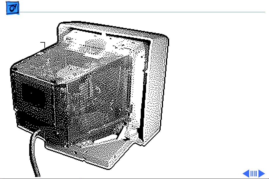
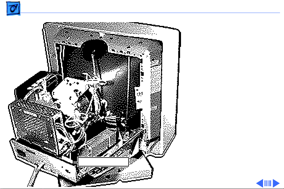
Take Apart Rear Cover - 1
Rear Cover
No preliminary steps are
required before you begin
this procedure.
±
Rear Cover
Warning:
contains high voltage and a
high-vacuum picture tube.
To prevent serious injury,
review CRT safety in
Bulletins/Safety.
This product
Page 44

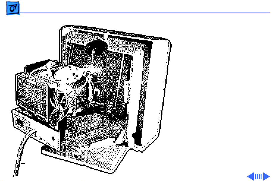
Take Apart Rear Cover - 2
1 With the monitor face-
down on a protective pad,
remove the four case
Video
Cable
screws and pull the rear
cover off the chassis.
2 Route the video cable
through the cover.
Page 45

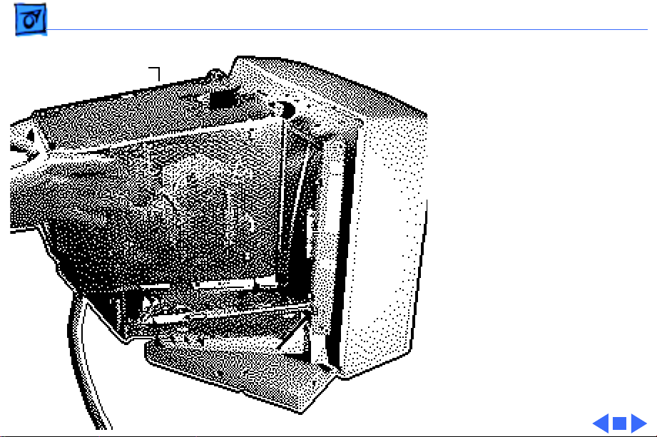
Take Apart Bezel - 3
Bezel
Before you begin, remove
Bezel
the following:
• Rear cover
• EMI shield
±
Warning:
contains high voltage and a
high-vacuum picture tube.
To prevent serious injury,
review CRT safety in
Bulletins/Safety.
This product
Page 46

Take Apart Bezel - 4
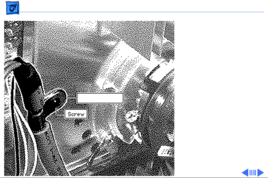
1 Remove the grounding
screw.
Grounding Screw
Page 47

Take Apart Bezel - 5
2 Remove the four large
Bezel
hex head screws and
remove the bezel.
Hex Head Screw
Page 48
Take Apart EMI Shield - 6
EMI Shield
EMI Shield
Before you begin,
• Remove the rear cover
• Discharge the CRT
±
Warning:
contains high voltage and a
high-vacuum picture tube.
To prevent serious injury,
review CRT safety in
Bulletins/Safety.
±
Warning:
grounding wriststrap until
after discharging the CRT.
Note:
The EMI shield is not
replaceable.
This product
Never use a
Page 49

Take Apart EMI Shield - 7
1 Remove the 12 screws
from the shield. (Three
EMI Shield
screws are located on the
left side of the EMI
shield.)
Page 50
Take Apart EMI Shield - 8
EMI Shield
2 Slide the shield toward
the back of the monitor
and lift off the shield.
Page 51

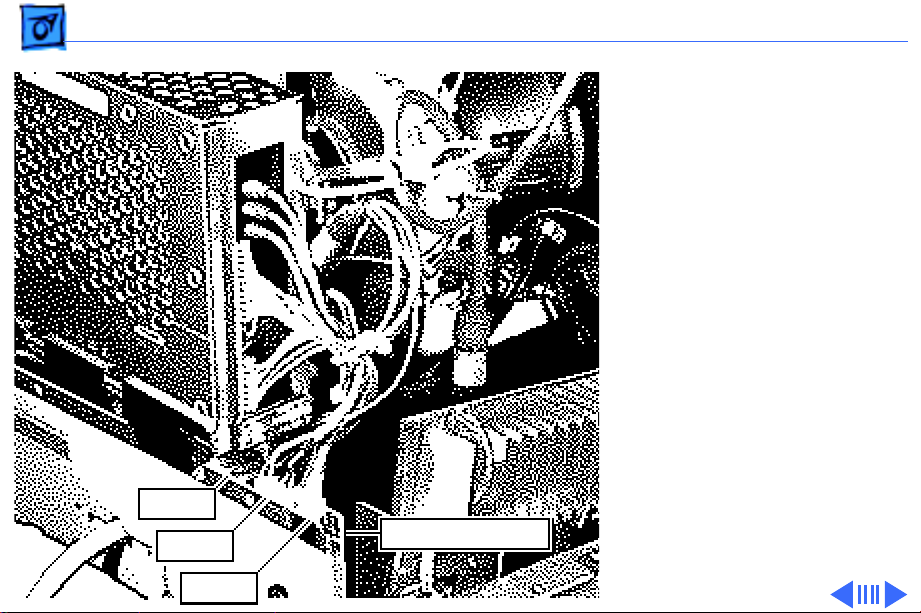
Take Apart CRT/Video Board - 9
CRT/Video Board
Before you begin,
CRT/Video
Board
• Remove the rear cover
• Discharge the CRT
• Remove the EMI shield
±
Warning:
contains high voltage and a
high-vacuum picture tube.
To prevent serious injury,
review CRT safety in
Bulletins/Safety.
This product
Page 52
Take Apart CRT/Video Board - 10
±
NTC Connector
Ground Strap
Warning:
grounding wriststrap until
after discharging the CRT.
1
Caution:
removing the ground
strap from the CRT/
video board, be careful
not to apply excessive
pressure to the neck of
the CRT.
Disconnect the ground
strap from the terminal
on the front of the CRT/
video board shield.
2 Disconnect the NTC
connector.
Never use a
When
Page 53

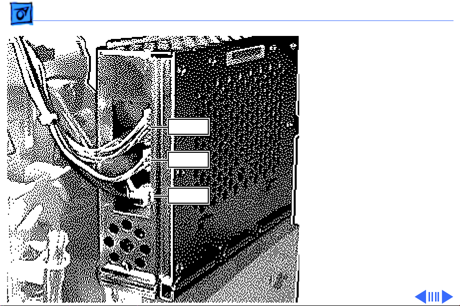
Take Apart CRT/Video Board - 11
R,G,B Cables
CN302
CN301
CN303
Caution:
When
disconnecting the following
cables from the CRT/video
board, be careful not to
apply excessive pressure to
the neck of the CRT.
3 Disconnect these cables
from the CRT/video
board:
• 11-wire cable
(CN302)
• 7-wire cable
(CN303)
• 3-wire cable
(CN301)
• R, G, and B video
cables
Page 54
Take Apart CRT/Video Board - 12
CN304
CN701
CN702
Caution:
When
disconnecting the following
cables from the CRT/video
board, be careful not to
apply excessive pressure to
the neck of the CRT.
4 Disconnect these cables
from the CRT/video
board:
• 1-wire cable
(CN702)
• 6-wire cable
(CN304)
• 3-wire cable
(CN701)
Ê
Page 55
Take Apart CRT/Video Board - 13
Video Cable Clip
Caution:
When removing
the video cable from the
CRT/video board, be careful
not to apply excessive
pressure to the neck of the
CRT.
5 Remove the screw
securing the video cable
clip to the CRT/video
board shield.
Page 56
Take Apart CRT/Video Board - 14
CRT/Video Board
Mounting Screw
Caution:
Twisting, bending,
or applying force to the
CRT/video board could
damage the neck of the CRT.
Be sure to pull the CRT/
video board straight off the
CRT.
6 Loosen the mounting
screw and pull the CRT/
video board straight off
the neck of the CRT.
Page 57

Take Apart CRT/Video Board - 15
7 Remove the two plastic
cable clips on the focus
VR control cables.
8 Disconnect the FV1 and
FV2 cables from the
FV1 Cable
FV2 Cable
Plastic Cable Clip
focus control board.
Page 58

Take Apart Power Supply - 16
Power Supply
Before you begin,
• Remove the rear cover
• Discharge the CRT
• Remove the EMI shield
±
Power Supply
Warning:
contains high voltage and a
high-vacuum picture tube.
To prevent serious injury,
review CRT safety in
Bulletins/Safety.
±
Warning:
grounding wriststrap until
after discharging the CRT.
This product
Never use a
Page 59
Take Apart Power Supply - 17
1 Disconnect these cables
from the power supply:
• 8-wire cable
(CN602)
CN602
Ground
Strap
CN603
CN604
•5-wire cable
(CN603)
• 2-wire cable
(CN604)
• Ground strap
2 Remove the wiring
harness from the plastic
cable clip.
Page 60

Take Apart Power Supply - 18
3 Disconnect these cables
from the AC interconnect
board:
• CN1600
• CN1601
4 Remove plastic cable
clips.
CN1601
CN1600
Plastic Cable Clips
Page 61

Take Apart Power Supply - 19
5 Remove the screw
securing the ground
strap to the chassis.
6 Remove the screw
securing the power
Screw
supply to the chassis.
7 Slide the power supply
toward the rear of the
monitor and lift out the
power supply.
Ground Strap Screw
Page 62

Take Apart Power Supply - 20
8 D isconnect connector
CN601.
CN601
Page 63

Take Apart Fuse - 21
Fuse
Before you begin,
• Remove the rear cover
• Discharge the CRT
• Remove the EMI shield
• Remove the power supply
±
Warning:
contains high voltage and a
high-vacuum picture tube.
To prevent serious injury,
review CRT safety in
Bulletins/Safety.
Fuse
This product
Page 64
Take Apart Fuse - 22
±
Warning:
grounding wriststrap until
after discharging the CRT.
1 Remove the plastic cover
from the fuse holder.
2 Pry the fuse from the
fuse holder using a
jeweler’s screwdriver.
Never use a
Fuse Holder
Replacement Note:
sure to replace the fuse
with another fuse of the
same amperage and
voltage rating.
Be
Page 65

Take Apart Focus VR Control - 23
Focus VR Control
Before you begin,
• Remove the rear cover
• Discharge the CRT
• Remove the EMI shield
±
Warning:
contains high voltage and a
high-vacuum picture tube.
To prevent serious injury,
review CRT safety in
Bulletins/Safety.
Focus VR Control
This product
Page 66
Take Apart Focus VR Control - 24
±
FV1 Cable
VIDF Cable
FV2 Cable
HIDF Cable
MV Cable
Warning:
grounding wriststrap until
after discharging the CRT.
1 Disconnect these cables
from the focus control:
•MV
• FV1
• FV2
• VIDF
• HIDF
Never use a
Page 67
Take Apart Focus VR Control - 25
2 Remove the screw
securing the ground
strap to the chassis.
Focus Control
Focus Control
Screw
3 Remove the screw
securing the focus
control to the chassis.
4 Lift out the focus
control.
Ground
Strap
Screw
Page 68
Take Apart AC Inlet Assembly - 26
AC Inlet Assembly
Before you begin,
• Remove the rear cover
• Discharge the CRT
• Remove the EMI shield
• Remove the power supply
±
Warning:
contains high voltage and a
high-vacuum picture tube.
To prevent serious injury,
review CRT safety in
Bulletins/Safety.
AC Inlet Assembly
This product
Page 69

Take Apart AC Inlet Assembly - 27
±
CN1601
CN1600
Warning:
grounding wriststrap until
after discharging the CRT.
1 Disconnect these cables
from the AC interconnect
board:
• CN1600
• CN1601
2 Remove the screw
securing the AC inlet
ground strap to the
chassis.
Screw
Never use a
Page 70
Take Apart AC Inlet Assembly - 28
3 Remove the two screws
securing the AC inlet
assembly to the chassis.
4 Lift out the AC inlet
assembly.
Screw
Screw
AC Inlet
Assembly
Page 71
Take Apart Serial I/O Board - 29
Serial I/O Board
Before you begin,
• Remove the rear cover
• Discharge the CRT
• Remove the EMI shield
±
Serial I/O Board
Warning:
contains high voltage and a
high-vacuum picture tube.
To prevent serious injury,
review CRT safety in
Bulletins/Safety.
±
Warning:
grounding wriststrap until
after discharging the CRT.
This product
Never use a
Page 72

Take Apart Serial I/O Board - 30
1 Disconnect these cables
from the serial I/O
board:
• CN250
• CN253 (from video
cable)
• CN254 (from CRT/
video board)
CN253
Screw
CN254
Screw
CN250
Serial I/O Board
2 Remove the two screws
securing the serial I/O
board to the rear panel.
3 Lift out the serial I/O
board.
Page 73

Take Apart Serial I/O Board - 31
Replacement Note:
3-pin connector from
the video cable connects
to connector CN253 and
the 3-pin connector
from the CRT/video
board connects to
connector CN254.
The
Page 74
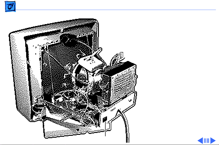
Take Apart Video Cable - 32
Video Cable
Before you begin,
• Remove the rear cover
• Discharge the CRT
• Remove the EMI shield
±
Video Cable
Warning:
contains high voltage and a
high-vacuum picture tube.
To prevent serious injury,
review CRT safety in
Bulletins/Safety.
±
Warning:
grounding wriststrap until
after discharging the CRT.
This product
Never use a
Page 75

Take Apart Video Cable - 33
1 Disconnect connector
CN253 from the serial
I/O board.
2 Disconnect the R, G, and
B cables from the CRT/
R,G,B Cables
CN253
Serial I/O Board
video board.
Page 76

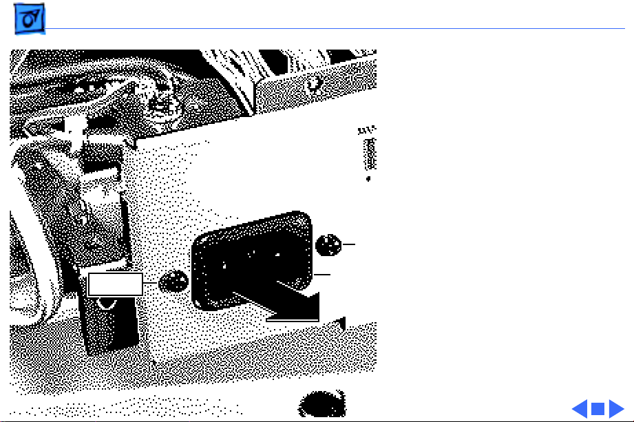
Take Apart Video Cable - 34
3 Caution: When
removing the video
cable from the CRT/
video board, be careful
not to apply excessive
pressure to the neck of
the CRT.
Remove the screw
securing the video cable
Video Cable Clip
clip to the CRT/video
board shield.
4 Remove the plastic cable
clip.
Page 77

Take Apart Video Cable - 35
5 Remove the two screws
securing the rear panel
to the chassis.
6 Rotate the rear panel
away from the chassis.
7 Remove the rear panel
from the chassis.
Rear Panel
Page 78

Take Apart Video Cable - 36
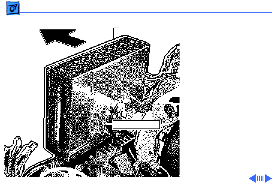
8 Remove the two screws
securing the cable
clamp to the rear panel.
9 Remove the video cable.
Screw Screw
Page 79

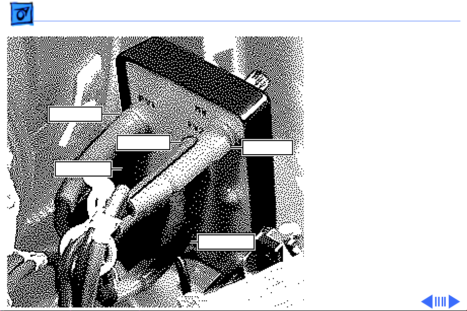
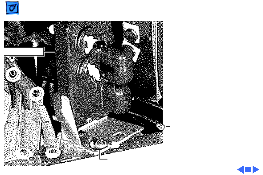
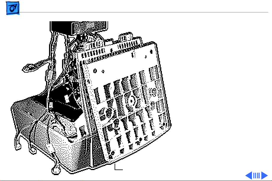
Take Apart Main Deflection Board - 37
Main Deflection Board
Before you begin,
• Remove the rear cover
• Discharge the CRT
• Remove the EMI shield
• Remove the power supply
±Warning: This product
contains high voltage and a
high-vacuum picture tube.
To prevent serious injury,
review CRT safety in
Bulletins/Safety.
Main Deflection Board
Page 80

Take Apart Main Deflection Board - 38
1 Disconnect the MV cable
from the focus VR
control.
2 Remove the two plastic
cable clips on the focus
VR control cables.
Plastic Clip
Plastic Clip
MV Cable
3 Remove the screw
securing the ground
strap to the chassis.
4 Remove the screw
securing the focus
control to the chassis.
5 Lift out the focus
control and let it hang
outside the chassis.
Page 81
Take Apart Main Deflection Board - 39
6 Disconnect these cables
from the serial I/O
board:
• CN250
• CN253 (from video
cable)
• CN254 (from CRT/
video board)
Replacement Note: The
3-pin connector from
the video cable connects
to connector CN253 and
the 3-pin connector
from the CRT/video
board connects to
CN253
CN254
CN250
Serial I/O Board
connector CN254.
Ê
Page 82

Take Apart Main Deflection Board - 40
7 Caution: When
disconnecting the
following cables from
the CRT/video board, be
careful not to apply
R,G,B Cables
excessive pressure to
the neck of the CRT.
Disconnect these cables
from the CRT/video
CN302
board:
• 11-wire cable
(CN302)
• 7-wire cable
(CN303)
• R, G, and B video
CN303
cables
Ê
Page 83
Take Apart Main Deflection Board - 41
8 Caution: When
removing the video
cable from the CRT/
video board, be careful
not to apply excessive
pressure to the neck of
the CRT.
Remove the screw
securing the video cable
Video Cable Clip
clip to the CRT/video
board shield.
Page 84

Take Apart Main Deflection Board - 42
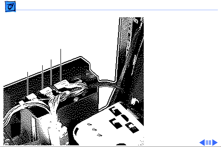
9 Disconnect these cables
from the main deflection
board:
• 2-wire cable
(CN401)
• 2-wire cable
(CN502)
• 2-wire cable
(CN1604)
• 6-wire cable
(CN505)
• 5-wire cable
(CN504)
• 5-wire cable
(CN400)
Page 85

Take Apart Main Deflection Board - 43
• 6-wire cable
(CN501)
• gold-colored connector
• 6-pin connector
(control panel)
Page 86

Take Apart Main Deflection Board - 44
10 Remove the cables from
the plastic cable clip.
Page 87

Take Apart Main Deflection Board - 45
11 Remove the two screws
securing the main
deflection board carrier
to the chassis. (Only one
screw is shown in the
illustration. The other
screw is on the opposite
side of the carrier.)
12 Slide back the carrier.
13 Remove the main
deflection board.
Screw
Page 88

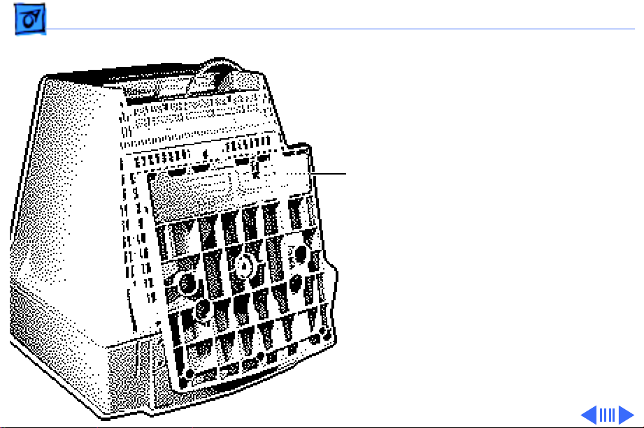
Take Apart Microprocessor Board - 46
Microprocessor Board
Before you begin,
• Save EEPROM settings
• Remove the rear cover
• Discharge the CRT
• Remove the EMI shield
• Remove the power supply
• Remove the main
deflection board
Important: Before you
Microprocessor Board
replace the microprocessor
board, save the EEPROM
settings. See
Troubleshooting for
instructions.
Page 89

Take Apart Microprocessor Board - 47
±Warning: This product
contains high voltage and a
high-vacuum picture tube.
To prevent serious injury,
review CRT safety in
Bulletins/Safety.
±Warning: Never use a
grounding wriststrap until
after discharging the CRT.
Page 90

Take Apart Microprocessor Board - 48
Important: Make sure you
save the EEPROM settings
CN908
before replacing the
microprocessor board.
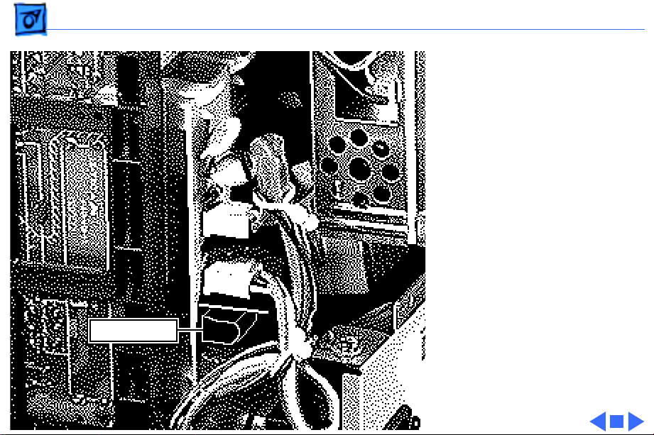
1 Disconnect these cables
CN902
from the
microprocessor board:
CN901
• 11-wire cable
(CN901)
• 7-wire cable
(CN902)
• 6-wire cable
CN907
(CN907)
• 5-wire cable
(CN908)
2 Remove the
microprocessor board.
Page 91
Take Apart Tilt/Swivel Assembly - 49
Tilt/Swivel Assembly
Before you begin,
• Remove the rear cover
• Discharge the CRT
• Remove the EMI shield
• Remove the power supply
• Remove the main
deflection board
±Warning: This product
contains high voltage and a
high-vacuum picture tube.
To prevent serious injury,
review CRT safety in
Bulletins/Safety.
Tilt/Swivel
Assembly
Page 92

Take Apart Tilt/Swivel Assembly - 50
±Warning: Never use a
grounding wriststrap until
after discharging the CRT.
1 With the monitor face-
down on a protective pad,
remove the two screws
securing the tilt/swivel
assembly to the chassis.
(Only one screw is
shown in the
illustration. The other
screw is on the opposite
Screw
side of the tilt/swivel
assembly.)
2 Lift and remove the tilt/
swivel assembly.
Page 93

Take Apart Control Panel - 51
Control Panel
Before you begin,
• Remove the cover
• Discharge the CRT
• Remove the anode cap
• Remove the EMI shield
• Remove the power supply
• Remove the main
deflection board
• Remove the tilt/swivel
assembly
Control Panel
Page 94

Take Apart Control Panel - 52
±Warning: This product
contains high voltage and a
high-vacuum picture tube.
To prevent serious injury,
review CRT safety in
Bulletins/Safety.
±Warning: Never use a
grounding wriststrap until
after discharging the CRT.
Page 95

Take Apart Control Panel - 53
1 Remove the screw
securing the control
panel ground strap to the
chassis.
2 Remove the ground wire
from the plastic cable
Grounding Strap
clip.
3 Remove the two screws
securing the control
panel board support to
the front bezel.
4 Lift out the control panel
board and support.
Plastic
Cable
Clip
Control
Panel
Page 96
Take Apart ADB Board - 54
ADB Board
No preliminary steps are
required before you begin
this procedure.
ADB Board
Page 97

Take Apart ADB Board - 55
1 With the monitor face-
down on a protective pad,
remove the two screws
securing the ADB board
cover and remove the
cover.
2 Lift out the ADB board.
Page 98
K
Service Source
Adjustments
Apple Multiple Scan 20 Display
Page 99

Adjustments Brightness and Contrast - 1
Brightness and Contrast
No preliminary steps are
required before you begin
this procedure.
Adjustment controls are
located on the front panel.
Front Panel
Page 100
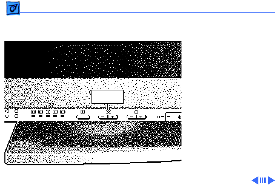
Adjustments Brightness and Contrast - 2
Brightness
1 Press the + button to
increase the brightness.
2 Press the – button to
decrease the brightness.
Brightness
Controls
 Loading...