

Page 1
K
Service Source
Macintosh 12 RGB Display
Page 2
K
Service Source
Specifications
Macintosh 12" RGB Display
Page 3
Specifications Characteristics - 1
Characteristics
Picture Tube
Screen Resolution
Scan Rates
12-in. viewable diagonal screen
90° deflection angle; black matrix-type dot screen
Phosphor type P22 (aluminized)
Spherical, antiglare surface
512x384 lines; 64 dpi
Displays up to 256 colors with Macintosh Display Card 4•8 and
16.7 million colors with Macintosh Display Card 8•24
Vertical refresh rate: 60.15 Hz
Horizontal scan rate: 24.48 kHz
Rise and fall time: 27 ns maximum
Page 4

Specifications Characteristics - 2
Active V ideo Display Area
Input Signals
8.08 in. by 6.02 in. (205 mm by 153 mm)
Video: red, green, and blue analog video; RS-343 standard
Page 5

Specifications Controls - 3
Controls
User Controls
Rear panel: power switch
Right side: brightness and contrast controls
Page 6

Specifications Physical and Electrical - 4
Physical and Electrical
Power Supply (International)
Power Supply (Domestic)
Size and Weight
Universal power supply
Voltage: 90–270 VAC, self-configuring
Frequency: 47–63 Hz, single-phase
Power: 90 W maximum
Voltage: 100–120 VAC
Frequency: 50–60 Hz
Power: 90 W maximum
Height: 12.2 in. (310 mm)
Width: 14.4 in. (365 mm)
Depth: 10.0 in. (253 mm)
Weight: 35 lb. (15.9 kg)
Page 7

Specifications Operating Environment - 5
Operating Environment
Temperature
Humidity
Altitude
50°F–104°F (10°C–40°C)
95% maximum, noncondensing
10,000 ft. (3,048 m) maximum
104°F (40°C) operation from 0–7000 ft. (2,134 m) and derated
linearly to maximum 64°F (25°C) at 10,000 ft.
Page 8
K
Service Source
Troubleshooting
Macintosh 12" RGB Display
Page 9

Troubleshooting General - 1
General
The Symptom Charts included in this chapter will help you
diagnose specific symptoms related to your product. Because cures
are listed on the charts in the order of most likely solution, try
the first cure first. Verify whether or not the product continues to
exhibit the symptom. If the symptom persists, try the next cure.
(Note: If you have replaced a module, reinstall the original module
before you proceed to the next cure.)
If you are not sure what the problem is, or if the Symptom Charts
do not resolve the problem, refer to the Flowchart for the product
family.
For additional assistance, contact Apple Technical Support.
Page 10

Troubleshooting Symptom Charts/No Raster - 2
Symptom Charts
No Raster
No raster, LED off 1 Ensure monitor’s video cable is connected to the computer or
the video card in the computer.
2 Check power cord.
3 Check internal power connectors.
4 Replace blown fuse.
5 Replace external power cable assembly.
6 Replace main deflection board.
No raster, LED on 1 Ensure monitor’s video cable is connected to the computer or
the video card in the computer.
2 Adjust contrast and brightness user controls.
3 Verify that video card in monitor is working properly.
4 Check main deflection board and CRT/video board connectors.
5 Replace blown fuse.
6 Perform screen adjustment.
7 Replace main deflection board.
8 Replace CRT/video board.
9 Replace CRT.
Page 11
Troubleshooting Symptom Charts/Geometry - 3
Geometry
Raster size short/
tall, narrow/wide
Raster not centered 1 Verify that distortion is not due to environmental conditions.
Horizontal linearity
bad (screen sides
differ)
1 Adjust V-HEIGHT or H-WIDTH controls on main deflection
board.
2 Replace main deflection board.
3 Replace CRT.
Move monitor to another location.
2 Adjust H-CENT or V-CENT external controls.
3 Replace main deflection board.
Replace main deflection board.
Page 12
Troubleshooting Symptom Charts/Geometry
(Continued)
- 4
Geometry
Vertical linearity bad
(screen top and
bottom differ)
Raster bows 1 Verify that distortion is not due to environmental conditions.
1 Adjust V-LIN control on main deflection board.
2 Replace main deflection board.
Move monitor to another location.
2 Check V-HEIGHT and V-CENT adjustment controls and H-
WIDTH and H-CENT controls. (Some bowing from
environmental conditions is normal and is within
manufacturing tolerances. Slight bowing does not impair
functionality of monitor.)
3 Replace main deflection board.
4 Replace CRT.
(Continued)
Page 13
Troubleshooting Symptom Charts/Geometry
(Continued)
- 5
Geometry
Entire raster is tilted 1 Verify that distortion is not due to environmental conditions.
Move monitor to another location.
2 Adjust yoke assembly as follows:
• Switch off power and remove rear cover
• Loosen frontmost screw on neck of CRT
• Twist yoke assembly as appropriate
• Retighten screw on neck of CRT (Do not overtighten screw;
• Switch on monitor and check display
3 Replace main deflection board.
(Continued)
you could break neck of CRT.)
Page 14
Troubleshooting Symptom Charts/Geometry
(Continued)
- 6
Abnormal/distorted
raster (other than
above)
Geometry
1 Verify that distortion is not due to environmental conditions.
Move monitor to another location.
2 Check all cable connections.
3 Perform geometric adjustments.
4 Replace main deflection board.
5 Replace CRT/video board.
6 Replace CRT.
(Continued)
Page 15

Troubleshooting Symptom Charts/Synchronization - 7
Synchronization
Picture breaks into
diagonal lines
Picture rolls
vertically
Single vertical or
horizontal line on
screen
1 Connect another monitor to computer and verify video signal.
2 Adjust H-HOLD control on main deflection board.
3 Replace main deflection board.
1 Verify that video card in monitor is working properly.
2 Adjust V-HOLD control on main deflection board.
3 Replace main deflection board.
1 Check yoke connector DY.
2 Replace main deflection board.
3 Replace CRT.
Page 16

Troubleshooting Symptom Charts/Video - 8
Video
Predominant red,
blue, or green tint
Picture too dark or
too bright
1 Check video cable connection.
2 Verify that video card in monitor is working properly.
3 Perform white balance adjustments.
4 Replace CRT/video board.
5 Replace CRT.
1 Adjust contrast and brightness knobs.
2 Verify that video card in monitor is working properly.
3 Perform video adjustments (cutoff and white balance).
4 Replace main deflection board.
5 Replace CRT/video board.
6 Replace CRT.
Page 17
Troubleshooting Symptom Charts/Video
(Continued)
- 9
Video
Cannot adjust
brightness, contrast,
or color
Out of focus 1 Adjust focus control on flyback transformer.
1 Replace contrast/brightness assembly.
2 Replace main deflection board.
3 Replace CRT/video board.
2 Perform screen adjustment.
3 Replace main deflection board.
4 Replace CRT.
(Continued)
Page 18
Troubleshooting Symptom Charts/Miscellaneous - 10
Miscellaneous
Intermittently shuts
down
Picture jitters or
flashes
Flashing or wavy
screen
Black spots on screen
(burnt phosphors)
1 Ensure monitor’s video cable is connected to the computer or
the video card in the computer.
2 Replace main deflection board.
1 Check that ground cables are secure.
2 Check that adjacent computer equipment is properly
grounded. Move other electrical devices away from monitor.
Shut off fluorescent lights.
3 Replace main deflection board.
1 Crimp metal connector tabs on video connector.
2 Replace main deflection board.
Replace CRT.
Page 19
K
Service Source
T ak e Apart
Macintosh 12" RGB Display
Page 20

Take Apart Rear Cover - 1
Rear Cover
No preliminary steps are
required before you begin
this procedure.
±
Rear Cover
Warning:
contains high voltage and a
high-vacuum picture tube.
To prevent serious injury,
review CRT safety in
Bulletins/Safety.
This product
Page 21
Take Apart Rear Cover - 2
1 Place the monitor face-
down on a protective pad
and remove the two case
screws.
2 Separate the bottom of
the rear cover from the
bezel.
Page 22
Take Apart Rear Cover - 3
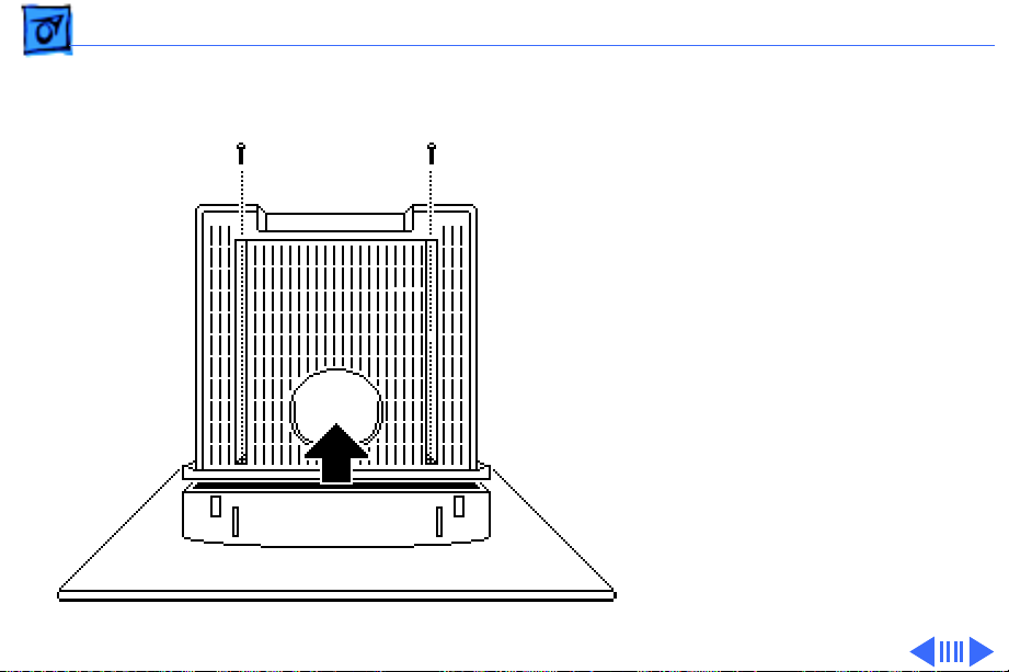
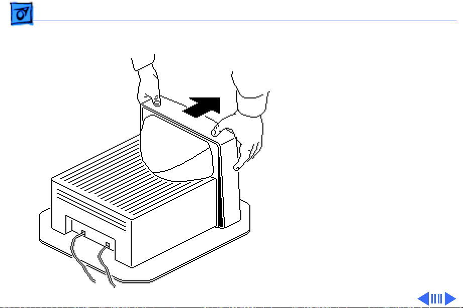
3 Set the monitor upright.
4 Press down about one
inch from the outside
edges of the bezel to
separate the top of the
rear cover from the
bezel.
Page 23
Take Apart Rear Cover - 4
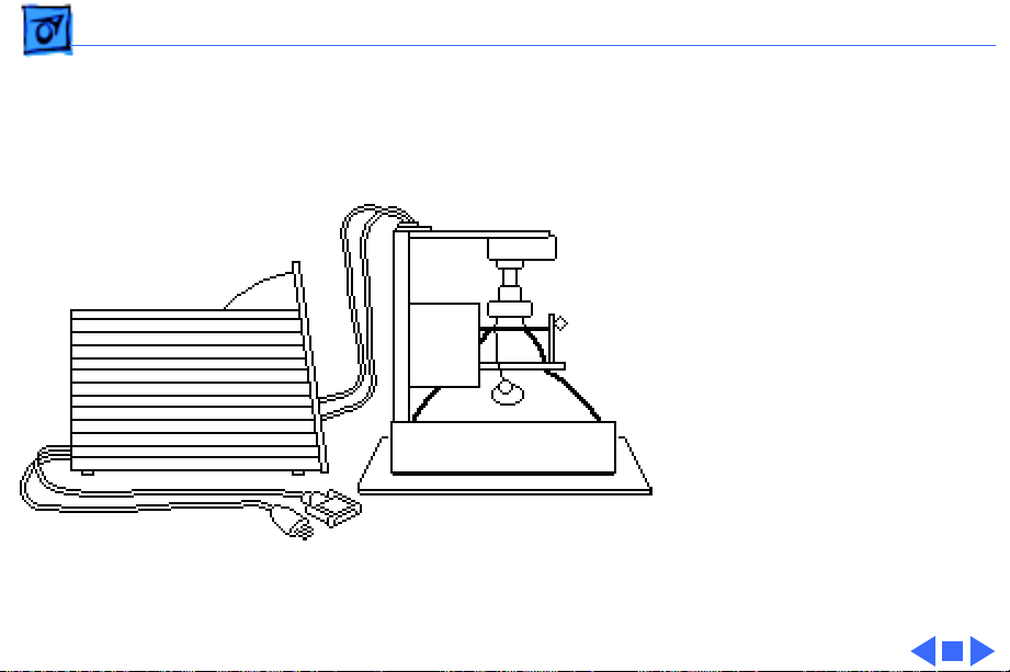
5 Place the monitor face-
down on a protective pad.
6 Lift off the loosened
rear cover.
7 Pull the AC power cord
and video cable through
the cover.
Page 24
Take Apart Contrast/Brightness Assembly - 5
Contrast/ Brightness Assembly
Contrast/Brightness
Assembly
Before you begin,
• Remove the rear cover
• Discharge the CRT
• Remove the anode cap
±
Warning:
contains high voltage and a
high-vacuum picture tube.
To prevent serious injury,
review CRT safety in
Bulletins/Safety.
±
Warning:
This product
Never use a
Page 25
Take Apart Contrast/Brightness Assembly - 6
grounding wriststrap until
after discharging the CRT.
J204
1 Disconnect the six-wire
cable from connector
J204 on the CRT/video
Cable Retainer
board. Remove the six
wires from the cable
retainer.
Mounting Bracket
2 Remove brightness
VR204
board VR204 and
contrast board VR203
from the mounting
VR203
bracket.
3 Unhook and pull the six
wires through the back
of the mounting bracket.
Page 26
Take Apart Contrast/Brightness Assembly - 7
4 Pull off the two control
knobs.
5 Disconnect cable
J206
connector J206 from the
brightness board and
cable connector J205
Brightness Board - VR204
Plastic Control Knobs
J205
from the contrast board.
Contrast Board
VR203
Page 27
Take Apart Fuse - 8
Fuse
Before you begin,
• Remove the rear cover
• Discharge the CRT
• Remove the anode cap
±
Fuse
Warning:
contains high voltage and a
high-vacuum picture tube.
To prevent serious injury,
review CRT safety in
Bulletins/Safety.
±
Warning:
grounding wriststrap until
after discharging the CRT.
This product
Never use a
Page 28
Take Apart Fuse - 9
Using a small flat-blade
screwdriver, pry the
defective fuse from
connector F901 on the
deflection board.
F901
Page 29
Take Apart CRT/Video Board - 10
CRT/Video Board
Before you begin,
• Remove the rear cover
• Discharge the CRT
• Remove the anode cap
±
CRT/Video Board
Warning:
contains high voltage and a
high-vacuum picture tube.
To prevent serious injury,
review CRT safety in
Bulletins/Safety.
±
Warning:
grounding wriststrap until
after discharging the CRT.
This product
Never use a
Page 30
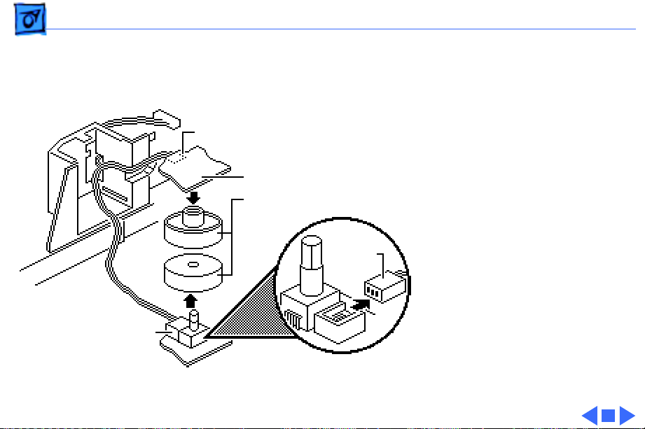
Take Apart CRT/Video Board - 11
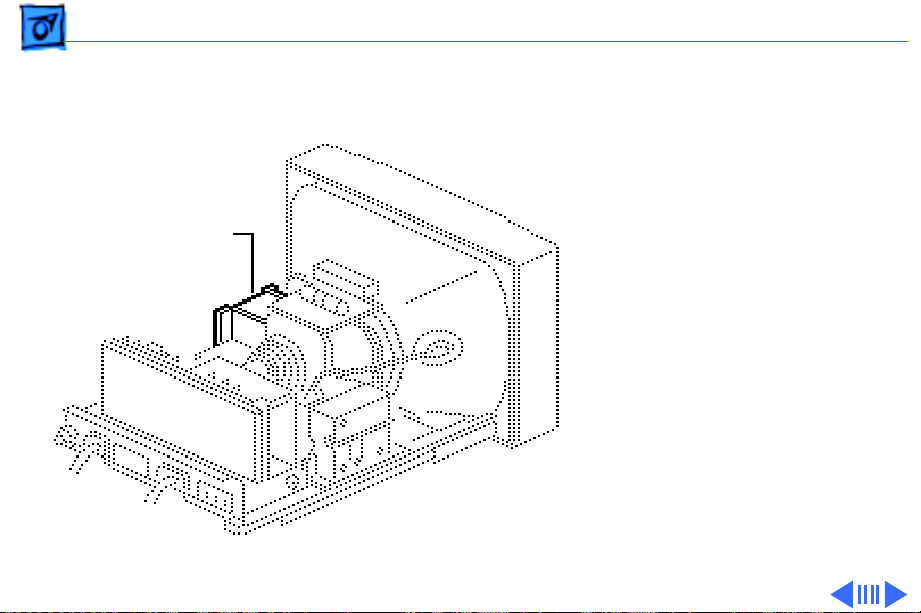
1 Remove the screw that
secures the video cable
to the cable clamp at the
back of the CRT/video
board.
2 Remove the video cable
from the clamp and
remove the clamp from
the CRT/video board.
Page 31

Take Apart CRT/Video Board - 12
J203
SC
J204
J201
J202
3 Disconnect the following
cable connectors from
the CRT/video board:
• 6-wire cable from
J204
• 8-wire video cable
from J201
• Single-pin cable from
SC
• 5-wire, 7-pin cable
from J202
• 6-wire, 8-pin cable
from J203
Page 32

Take Apart CRT/Video Board - 13
4
Note:
To unhook the CRT
ground cable, you must
Plastic Locking Nut
first press the small
metal catch in the
center of the connector.
Disconnect the CRT
ground cable from
Cable Retainer
connector PIN 1 on the
CRT/video board.
5 Remove the two cables
from the cable retainer
on the main deflection
board beneath the neck of
the CRT.
Pin 1
Page 33

Take Apart CRT/Video Board - 14
6 Loosen (turn clockwise,
as viewed from the rear
Plastic Locking Nut
of the monitor) the
plastic locking nut on the
neck of the CRT.
Cable Retainer
Pin 1
Page 34

Take Apart CRT/Video Board - 15
Note:
To remove the CRT/
video board over the rear
metal chassis, tilt the CRT
assembly slightly.
7 Grasp the back of the
CRT/video board with
CRT/Video Board
both hands and pull the
board straight back off
the neck of the CRT. Note
that a cable still
connects the CRT/video
board to the flyback
transformer.
Page 35

Take Apart CRT/Video Board - 16
8 Place the CRT/video
board on the protective
mat next to the flyback
transformer.
9 Unfasten the two side
tabs and open the white
plastic cover over
Q201
connector Q201. You
may need to use a small
flat-blade screwdriver
to open the tabs.
Page 36

Take Apart CRT/Video Board - 17
10
Caution:
To avoid
damaging the CRT/video
board, use a low-wattage
soldering iron. Touch
only the connector Q201
terminal with the
soldering iron.
Q201
Desolder the flyback
transformer cable from
connector Q201.
Page 37

Take Apart External Power Cable - 18
External Power Cable
Before you begin,
• Remove the rear cover
• Discharge the CRT
• Remove the anode cap
±
External Power Cable
Warning:
contains high voltage and a
high-vacuum picture tube.
To prevent serious injury,
review CRT safety in
Bulletins/Safety.
±
Warning:
grounding wriststrap until
after discharging the CRT.
This product
Never use a
Page 38

Take Apart External Power Cable - 19
Note:
The international
version of the 12” RGB
display has a detachable
external power cable.
1 Disconnect the two-
wire, three-pin power
connector from the AC
AC Connector
connector on the main
deflection board.
Page 39

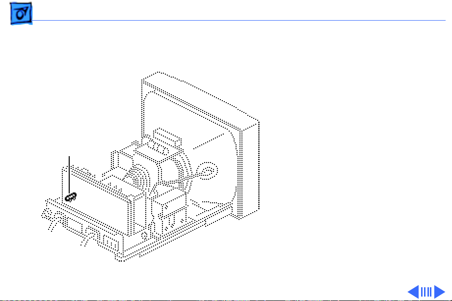
Take Apart External Power Cable - 20
2 Using a 9/32-inch hex
driver or a small
adjustable wrench,
remove the hex screw
that secures the AC
ground cable to the rear
of the metal chassis.
Page 40

Take Apart External Power Cable - 21
3 R emove the two screws
that secure the power
cable to the metal
chassis.
4 Remove the power cable.
Page 41

Take Apart CPU-to-Monitor Cable - 22
CPU-to-Monitor Cable
Before you begin,
• Remove the rear cover
• Discharge the CRT
• Remove the anode cap
±
CPU-to-Monitor Cable
Warning:
contains high voltage and a
high-vacuum picture tube.
To prevent serious injury,
review CRT safety in
Bulletins/Safety.
±
Warning:
grounding wriststrap until
after discharging the CRT.
This product
Never use a
Page 42

Take Apart CPU-to-Monitor Cable - 23
1 Disconnect the eight-
CRT/Video Board
wire video connector
from connector J201 on
the CRT/video board.
J201
Page 43

Take Apart CPU-to-Monitor Cable - 24
2 R emove the screw that
secures the video cable
to the back of the CRT/
video board.
Remove the video cable
from the cable clamp.
Video Cable
Page 44

Take Apart CPU-to-Monitor Cable - 25
3 Remove the screw that
secures the video cable
to the mounting bracket
on the rear chassis.
Remove the video cable
from the cable clamp.
Page 45

Take Apart CPU-to-Monitor Cable - 26
4 Remove the two screws
that secure the video
cable to the metal
chassis.
5 Remove the video cable
from the chassis.
Page 46

Take Apart Main Deflection Board - 27
Main Deflection Board
Before you begin,
• Remove the rear cover
• Discharge the CRT
• Remove the anode cap
• Remove the CRT/video
board
• Remove the external
power cable
• Remove the CPU-to-
monitor cable
Main Deflection
Board
Page 47

Take Apart Main Deflection Board - 28
±
Warning:
contains high voltage and a
high-vacuum picture tube.
To prevent serious injury,
review CRT safety in
Bulletins/Safety.
±
Warning:
grounding wriststrap until
after discharging the CRT.
This product
Never use a
Page 48

Take Apart Main Deflection Board - 29
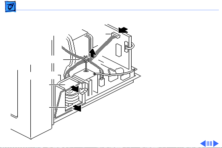
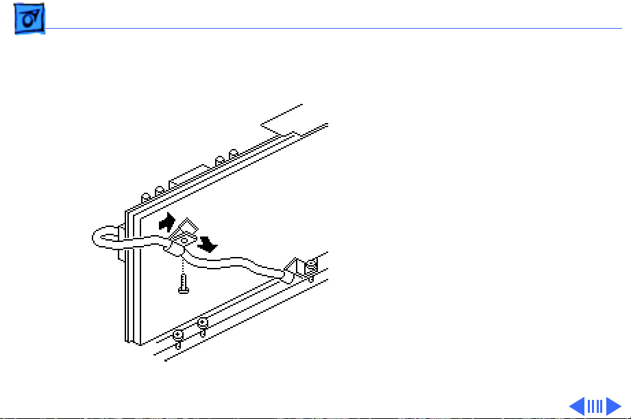
1 Disconnect the following
cable connectors from
the main deflection
board:
• 2-wire cable from PC
• 2-wire LED cable
from J502 (Detach
the LED cable from
the back of the
DY
flyback transformer.)
• 4-wire yoke cable
from DY
PC
J502
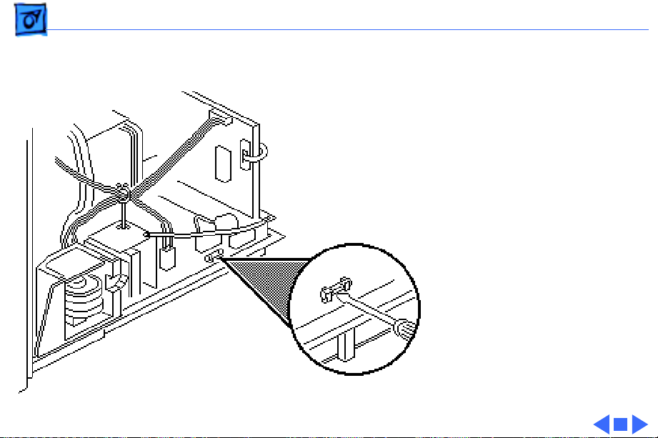
Page 49

Take Apart Main Deflection Board - 30
2 R emove the screw that
secures the two internal
ground cables to the
metal chassis.
3 Remove all cables from
the cable retainer on the
main deflection board.
Cable Retainer
Page 50

Take Apart Main Deflection Board - 31
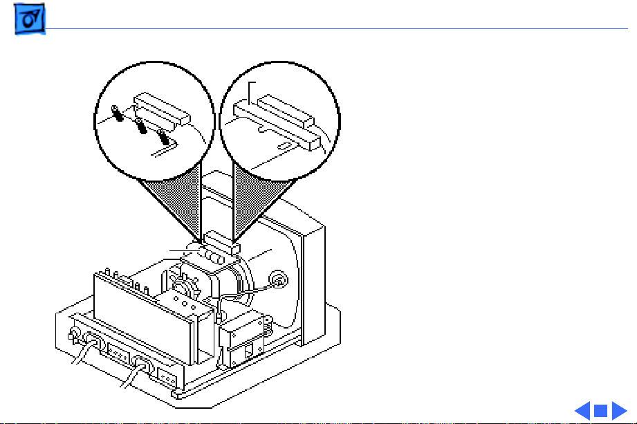
4 Remove the two screws
that secure the flyback
transformer to the right
stem of the plastic main
deflection board holder.
5 Remove the two screws
that secure the rear
chassis to the end of both
stems of the plastic main
deflection board holder.
Flyback
Transformer
Page 51

Take Apart Main Deflection Board - 32
6 Pull the main deflection
board straight out of the
channels in the plastic
main deflection board
holder.
Replacement Note:
and Rev. B versions of the
main deflection board are
not interchangeable and
must be replaced like-forlike.
Rev. A
Page 52

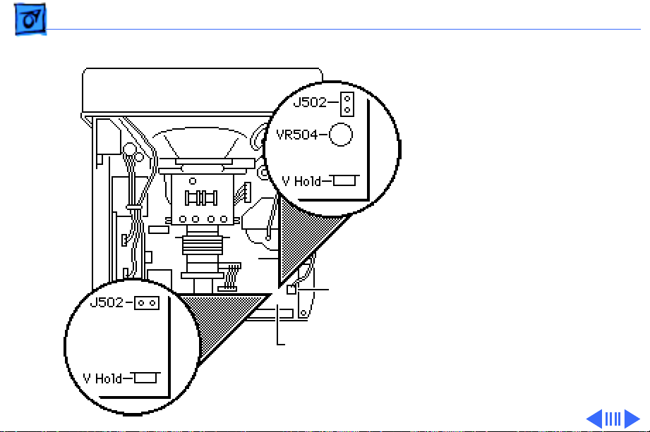
Take Apart Main Deflection Board - 33
To differentiate between
versions, look for a gray
coil (VR504) next to
connector J502 and do the
following:
• If the bad board does not
have coil VR504, order a
Rev. A main deflection
board.
• If the bad board has coil
VR504, order a Rev. B
main deflection board.
VR504
J502 Connector
Page 53

Take Apart Main Deflection Board Holder - 34
Main Deflection Board Holder
Before you begin,
• Remove the rear cover
• Discharge the CRT
• Remove the anode cap
• Remove the CRT/video
board
• Remove the main
deflection board
±
Main Deflection Board Holder
Warning:
contains high voltage and a
high-vacuum picture tube.
To prevent serious injury,
review CRT safety in
Bulletins/Safety.
This product
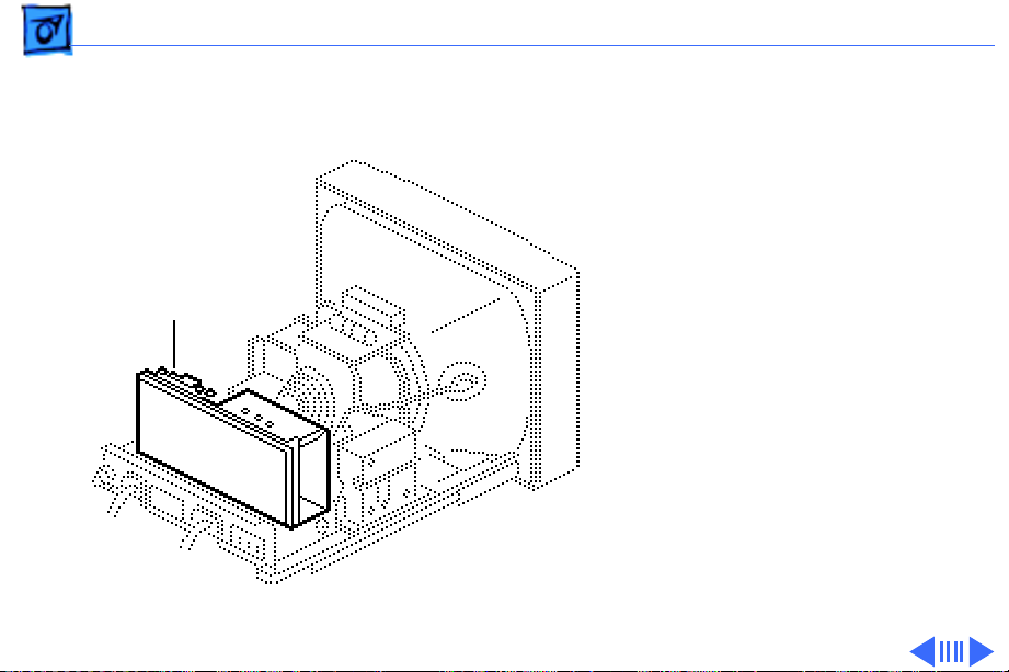
Page 54

Take Apart Main Deflection Board Holder - 35
±
Warning:
grounding wriststrap until
after discharging the CRT.
1 With the monitor face-
down on a protective pad,
lift and pull the left and
right front edges of the
main deflection board
holder to remove it
from the bezel.
Never use a
Page 55

Take Apart Main Deflection Board Holder - 36
2 R emove the mounting
screw and the contrast/
brightness assembly
from the main deflection
board holder.
Contrast/Brightness
Assembly
Page 56

Take Apart CRT Assembly - 37
CRT Assembly
Before you begin,
• Remove the rear cover
• Discharge the CRT
• Remove the anode cap
CRT Assembly
• Remove the CRT/video
board
• Remove the main
deflection board
• Remove the main board
holder
Page 57

Take Apart CRT Assembly - 38
±
Warning:
contains high voltage and a
high-vacuum picture tube.
To prevent serious injury,
review CRT safety in
Bulletins/Safety.
This product
±Warning: Never use a
grounding wriststrap until
after discharging the CRT.
Page 58

Take Apart CRT Assembly - 39
1 Caution: The neck of the
CRT is easily damaged.
Do not grab the neck of
the CRT to remove it
from the bezel.
Remove the four
mounting screws and
carefully lift the CRT
from the bezel. Place
the CRT face-down on the
protective pad.
Page 59

Take Apart CRT Assembly - 40
2 Remove the four spacers
from the plastic
standoffs at the corners
of the bezel.
Page 60
Take Apart CRT Assembly - 41
Revision A
Revision B
J502
Main Deflection
Board
Replacement Note: If you
are replacing the CRT, you
must order a replacement
CRT that is compatible with
the main deflection board in
the customer’s system.
Check the main deflection
board for resistor VR504.
• If VR504 is not present,
you have a Rev. A main
board. Order Standard
CRT 076-0384.
• If VR504 is present, you
have a Rev. B main board.
Order Low ELF CRT 076-
0395.
Page 61
Take Apart CRT Assembly - 42
Replacement Note: CRTs
Field Coil
ship in Standard and Low
ELF versions. Yoke boards
come in many variations. To
determine whether the CRT
Standard
CRT
Low ELF
CRT
is a Standard or Low ELF
CRT, check for field coils.
The Low ELF CRT has two
field coils, one on top and one
on the bottom of the CRT. The
Yoke Board
Standard CRT does not have
field coils.
Replacement Note: After
replacing a defective CRT,
perform the voltage
adjustment procedure (see
Adjustments).
Page 62

Take Apart LED Assembly Cable - 43
LED Assembly Cable
Before you begin,
• Remove the rear cover
• Discharge the CRT
• Remove the anode cap
• Remove the CRT/video
board
• Remove the main
deflection board
• Remove the main board
holder
• Remove the CRT assembly
LED Assembly
Cable
Page 63

Take Apart LED Assembly Cable - 44
LED Assembly
PC
±Warning: This product
contains high voltage and a
high-vacuum picture tube.
To prevent serious injury,
review CRT safety in
Bulletins/Safety.
±Warning: Never use a
grounding wriststrap until
after discharging the CRT.
1 Remove the black
degauss cable from the
bezel. Connector PC is
attached to the cable.
2 Remove the mounting
screw and the LED
assembly from the bezel.
Page 64

Take Apart Bezel - 45
Bezel
To remove the bezel,
• Remove the rear cover
• Discharge the CRT
Bezel
• Remove the anode cap
• Remove the CRT/video
board
• Remove the main
deflection board
• Remove the main board
holder
• Remove the CRT assembly
• Remove the LED assembly
Page 65

Take Apart Bezel - 46
±Warning: This product
contains high voltage and a
high-vacuum picture tube.
To prevent serious injury,
review CRT safety in
Bulletins/Safety.
Page 66

K
Service Source
Adjustments
Macintosh 12 RGB Display
Page 67

Adjustments Screen Voltage - 1
Screen Voltage
Before you begin, remove
the cover.
±
Warning:
contains high voltage and a
high-vacuum picture tube.
To prevent serious injury,
review CRT safety in
Bulletins/Safety.
This product
Page 68

Adjustments Screen Voltage - 2
±
Warning:
adjustments are made from
the rear of the computer,
position a mirror to view
the computer screen. Do not
reach around the computer
to adjust the controls.
Note:
If you have replaced
the main deflection board,
you must perform the
screen adjustments prior to
performing other
adjustments. If you have not
replaced the main deflection
board, go to the Geometry
adjustments.
Because
Page 69

Adjustments Screen Voltage - 3
Note:
The look and operation
of buttons and jacks on
voltmeters vary.
Note:
Perform the screen
voltage adjustment only if
one or more of the following
conditions apply:
• You have replaced the
main deflection board.
Voltmeter
• You have inadvertently
altered the screen
adjustment.
• You have replaced the
High-Voltage Probe
CRT/yoke assembly with
a different revision CRT/
yoke assembly.
Page 70

Adjustments Screen Voltage - 4
Note:
Performing the
screen voltage adjustment
requires a voltmeter and a
high-voltage probe (Apple
service part number 076-
0392).
1
Caution:
voltage probe other than
Apple part number
076-0392 could damage
the monitor.
Use only a high-voltage
probe that meets these
specifications:
• 40 KV (VDC) rating
• Input impedance of
1000 megohms
Using a high-
Page 71

Adjustments Screen Voltage - 5
• Banana clips to plug
into a voltmeter
• Alligator clip to
2 VDC Setting
connect to ground
2 Switch on the voltmeter
power and set the
Power
voltmeter to the 2 VDC
(or lowest) setting.
High-Voltage Probe
Page 72

Adjustments Screen Voltage - 6
3 Connect the high-
voltage probe twopronged connector to the
ground and voltage
receptacles on the
voltmeter.
Make sure the prong
with the ground tab is in
the ground receptacle.
Page 73

Adjustments Screen Voltage - 7
4 Switch on the monitor
and let it warm up for at
least 10 minutes.
5 Attach the ground clip
from the high-voltage
probe to the metal
chassis.
Page 74

Adjustments Screen Voltage - 8
6 Set the contrast knob to
maximum and the
brightness knob to the
center (detent) position.
Page 75

Adjustments Screen Voltage - 9
7 Use Display Service
Utility to display the
Full Black Screen test
pattern.
SUB-BRIGHT
Control
Full Black Screen
8 Turn the SUB-BRIGHT
control (VR202) all the
way down
(counterclockwise).
Page 76

Adjustments Screen Voltage - 10
9 To set the screen voltage,
first check the label on
the side of the CRT to
determine the type: CRT
type AT12A9SL or CRT
type M29JMN097X13.
Label
10±Warning:
Because
you must measure
voltages in excess of 500
volts DC, make sure the
high-voltage probe is
grounded to the metal
monitor chassis. Do not
short the probe between
the test point and
adjacent components.
Page 77

Adjustments Screen Voltage - 11
Touch the high-voltage
PIN 4
probe to the voltage test
point labeled SCREEN
(U.S. version) or PIN 4
(international version).
SCREEN
High-Voltage
Probe
11 Adjust the screen control
until the voltmeter
reads:
• 500 V (± .005 V) for
CRT AT12A9SLB
• 400 V (± .004 V) for
CRT M29JMN097X13
Screen
Control
Page 78

Adjustments Screen Voltage - 12
12 Disconnect the high-
voltage probe from the
monitor.
13 Press the space bar or
Gray Bars
click the mouse to
advance to the next test
pattern. Turn the SUBBRIGHT control
(VR202) until the
SUB-BRIGHT
Control
raster is visible.
14 Use Display Service
Utility to display the
Gray Bars test pattern.
Page 79

Adjustments Screen Voltage - 13
15 Adjust the SUB-BRIGHT
control until the first
bar is black and the
second bar is barely
Gray Bars
SUB-BRIGHT
Control
visible.
Page 80

Adjustments Screen Voltage - 14
SUB-CONTRAST
Control
All-White Screen
Important:
Readings from
light meter model L-248
and L-246 differ. Please
note which meter you are
using before making
adjustments. (See “Light
Meter Setup.”)
16 Using Display Service
Utility, display the AllWhite Screen test
pattern.
17 Using the light meter and
a two-inch plastic
screwdriver, adjust the
SUB-CONTRAST control
(VR201) until you get
the following:
Page 81

Adjustments Screen Voltage - 15
• Model 248: top of the
10 scale
• Model 246: 30 ft.
lamberts (± 3 ft.
All-White Screen
lamberts)
Note:
If you are unable
to adjust the SUBCONTRAST control to get
the correct reading,
SUB-CONTRAST
Control
perform the White
Balance video
adjustment.
Page 82

Adjustments Geometry - 16
Geometry
Before you begin, remove
the cover.
±
Geometry
Adjustment
Controls
Warning:
contains high voltage and a
high-vacuum picture tube.
To prevent serious injury,
review CRT safety in
Bulletins/Safety.
±
Warning:
adjustments are made from
the rear of the computer,
position a mirror to view
the computer screen. Do not
This product
Because
Page 83

Adjustments Geometry - 17
reach around the computer
to adjust the yoke.
Note:
Geometry adjustments
may be necessary whenever
you replace the main
deflection board, CRT, or
video board.
Note:
Do not attempt yoke
adjustments on this monitor.
The factory settings require
no adjustment.
Page 84

Adjustments Geometry - 18
Vertical Size
Note:
Vertical size, vertical
center, and horizontal
All-White Screen
V-HEIGHT
Control
center adjustments can be
performed without
removing the rear cover.
1 Use Display Service
Utility to display the
All-White Screen test
pattern.
2 Adjust the V-HEIGHT
control (VR404) with a
plastic screwdriver
until the raster height is
153 mm (± 2 mm) or 6
1/16 in. (± 1/16 in.).
Page 85

Adjustments Geometry - 19
Vertical Center
1 Using a plastic
screwdriver, adjust the
V-CENT control
(VR403) until the
raster is centered (top
to bottom) in the
display area.
2 Verify that the raster
height is 6 1/16 in. (±
1/16 in.) or 153 mm
(± 2 mm). If it is not,
repeat the Vertical Size
adjustment and, if
necessary, the Vertical
V-CENT Control
Center adjustment.
Page 86

Adjustments Geometry - 20
Horizontal Center
Using the plastic
screwdriver, adjust the HCENT control (VR503) until
the raster is centered (side
to side) in the display area.
Note:
If you cannot center
the raster, set the H-CENT
control at midrange and
perform the following steps.
H-CENT Control
Page 87

Adjustments Geometry - 21
Note:
Perform the following
steps only if you could not
center the raster using the
V-CENT and H-CENT
controls.
1 Switch off the monitor
and remove the rear
cover. See “Rear
Cover” in the Take Apart
chapter.
2 Switch on the monitor.
H-PHASE
Control
Page 88

Adjustments Geometry - 22
3 Using the plastic
screwdriver, adjust the
H-PHASE control
(VR501) until the
raster is positioned at
the visual midpoint of
the range of the HPHASE control.
Note:
You may need to
check the limits of the
H-PHASE control to find
its midpoint.
H-PHASE
Control
Page 89

Adjustments Geometry - 23
4 Using the plastic
screwdriver, adjust the
H-CENT control
(VR503) until the
raster is in the
approximate center of
the screen.
H-CENT
Control
Page 90

Adjustments Geometry - 24
Horizontal Size
H-WIDTH
Control
Before yu begin,
rear cover.
Using the hex-head insulated
adjustment tool, adjust the
H-WIDTH control (L501)
until the raster is 205 mm
(± 2 mm) or 8 3/32 in. (±
1/16 in.) wide.
remove the
Page 91

Adjustments Geometry - 25
Vertical Linearity
1 Use Display Service
Utility to display the
Crosshatch I test
Crosshatch I
V-LIN
Control
pattern.
2 Using a plastic
screwdriver, adjust the
V-LIN control until the
distance between the
horizontal lines is the
same at the top and
bottom of the screen.
Page 92

Adjustments Geometry - 26
Vertical Hold
1 Use Display Service
Utility to display the
All-White Screen
V-HOLD
Control
All-White Screen test
pattern.
2 Using a plastic
screwdriver, adjust the
V-HOLD control
(VR401) until the
raster stabilizes.
To check the
adjustment, switch the
monitor off and on. If the
raster stabilizes
immediately, V-HOLD is
correctly set.
Page 93

Adjustments Geometry - 27
Horizontal Hold
Using the plastic
screwdriver, adjust the HHOLD control (VR502) until
the raster stabilizes.
To check the adjustment,
switch the monitor off and
on. If the raster stabilizes
immediately, H-HOLD is
correctly set.
H-HOLD
Control
Page 94

Adjustments Geometry - 28
Focus
1 Use Display Service
Utility to display the
Focus test pattern.
Focus
FOCUS
Control
2 Using a plastic
screwdriver, adjust the
FOCUS control until the
Focus test pattern is as
clear as possible.
Page 95

Adjustments Video - 29
Video
Before you begin,
• Remove the cover
Video
Adjustment
Controls
• Remove the EMI shield
• Remove the video board
shield
±
Warning:
contains high voltage and a
high-vacuum picture tube.
To prevent serious injury,
review CRT safety in
Bulletins/Safety.
This product
Page 96

Adjustments Video - 30
Caution:
adjustments are made from
the rear of the computer,
position a mirror to view
the computer screen. Do not
reach around the computer
to adjust the controls.
Note:
adjustments only if the color
quality is unacceptable.
Because
Perform video
Page 97

Adjustments Video - 31
White Balance
Note:
Complete any
necessary geometry
Brightness
Contrast
Full Black Screen
adjustments before
performing the white
balance adjustments.
1 Turn on monitor power
and let the monitor
warm up for at least 10
minutes.
2 Use Display Service
Utility to display the
Full Black Screen.
3 Set the brightness
control and the contrast
control to maximum.
Page 98

Adjustments Video - 32
SUB-CONTRAST
DRIVE-BLUE
Control
DRIVE-RED
Control
Control
Green, Red, and
Blue Cutoff Controls
4 Preset these adjustment
controls:
• GREEN, RED, and
BLUE CUTOFF
controls to minimum.
• DRIVE-RED and
DRIVE-BLUE controls
to midrange.
• SUB-CONTRAST
control (VR201) to
midrange.
Page 99

Adjustments Video - 33
5 Adjust the SUB-BRIGHT
control (VR202) until
you cannot see the
raster, then turn up the
SUB-BRIGHT control
until the raster is
visible.
6 Adjust the GREEN CUT-
OFF control until green
SUB-BRIGHT
Control
GREEN
CUT-OFF
Control
is the predominant color.
Note:
The screen should
be dark, but with an
obvious green tint.
Page 100

Adjustments Video - 34
7 Use Display Service
Utility to display the
Gray Bars test pattern.
RED CUT-OFF
Control
Brightness
BLUE CUT-OFF
Control
Gray Bars
8 Set the brightness knob
to the center (detent)
position.
9 Alternately adjust the
RED and BLUE CUT-OFF
controls until there is no
predominant color in
the left three bars.
 Loading...