

Page 1
Color LaserWriter 12/600 PS and 12/660 PS
Service Technical Documentation
Steve Rancourt 5/95
This document was created with FrameMaker 4.0.4
Page 2
About Graphics
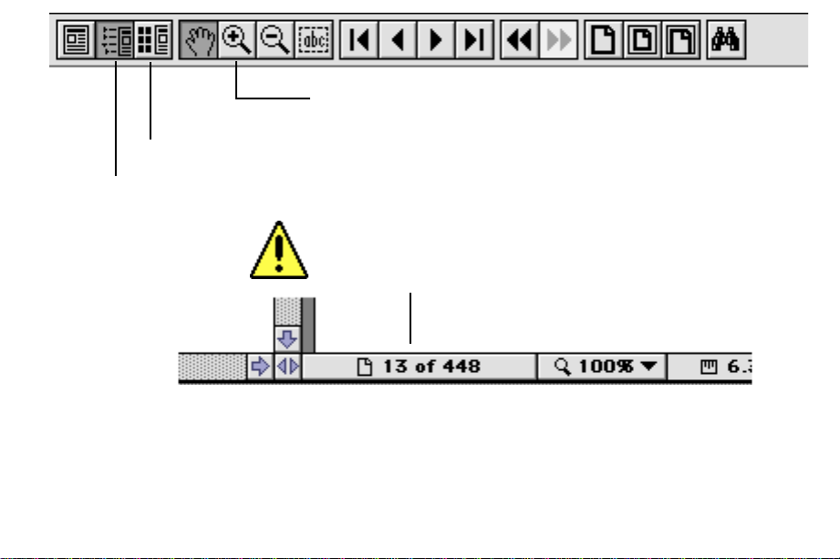
Using the magnifier tool enables you to zoom
Thumbnails
Bookmarks
Could not open the specified file...
If you get this message when trying to launch a QuickTime movie, you may not have
enough memory to run MoviePlayer. Try quitting out of other applications.
This error also may occur if you copied files from the CD to a hard drive and have not
foldered the files identically to the arrangement of folders on the CD.
into graphics and see greater detail.
About Printing
pages out of Acrobat. Page numbers that appear on the
paper do not reflect their true order within the document.
:
:
Always use these numbers when printing
Page 3

K
Service Source
Color LaserWriter
Color LaserWriter 12/600 PS
Color LaserWriter 12/660 PS
Page 4

Color LaserWriter 12/660 PS
96.11.13.15.58
Page 5
Color LaserWriter 12/660 PS 3–2
Overview
The Color LaserWriter 12/660 PS is an enhanced version of the
original Color LaserWriter 12/600 PS. The 12/660 engine and
plastics are identical to the original in every respect, and all
finished goods and service part numbers apply equally to both
printers. The sole differences between the two versions are in
the packaging and setup, the ROM and RAM on the I/O
controller board, and the driver software.
Packaging and Setup Changes
The Color LaserWriter 12/660 PS requires two extra steps
during setup, the leveling of the printer and the removal of oil
absorption sheets from the fuser assembly.
Note
: The orange flag that identifies the shipping screw has
also been enlarged in the new version of the printer.
The leveling procedure helps to alle viate oil o v erflow problems
within the fuser assembly. The level and shim kit that comes
with the 12/660 PS is also available separately as P/N 076-0622
for those who would to perform the procedure on the original
version of the printer. After removing the packing tape from
the outside of the printer, performing the leveling procedure
below before proceeding any further.
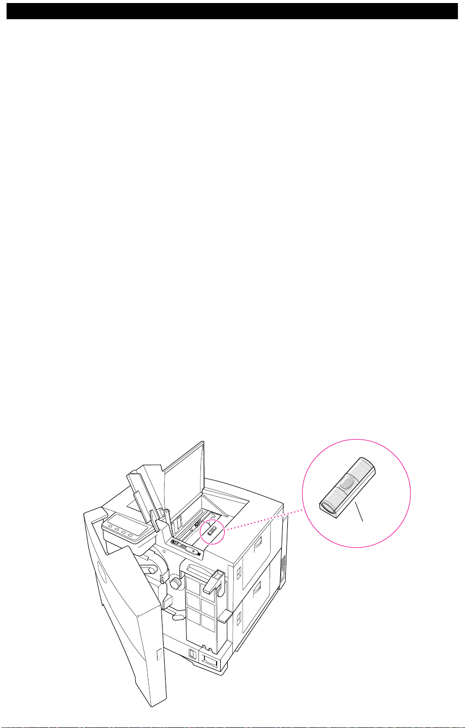
1 Remove the spirit level and the round black rubber shims from
their package. Snap the spirit level into its base.
2 Open the printer’s top access cover and place the spirit level on
top of the fuser to level the printer , first from front-to-back, then
from side-to-side.
Spirit Level
96.11.13.15.58
Page 6
Color LaserWriter 12/660 PS 3–3
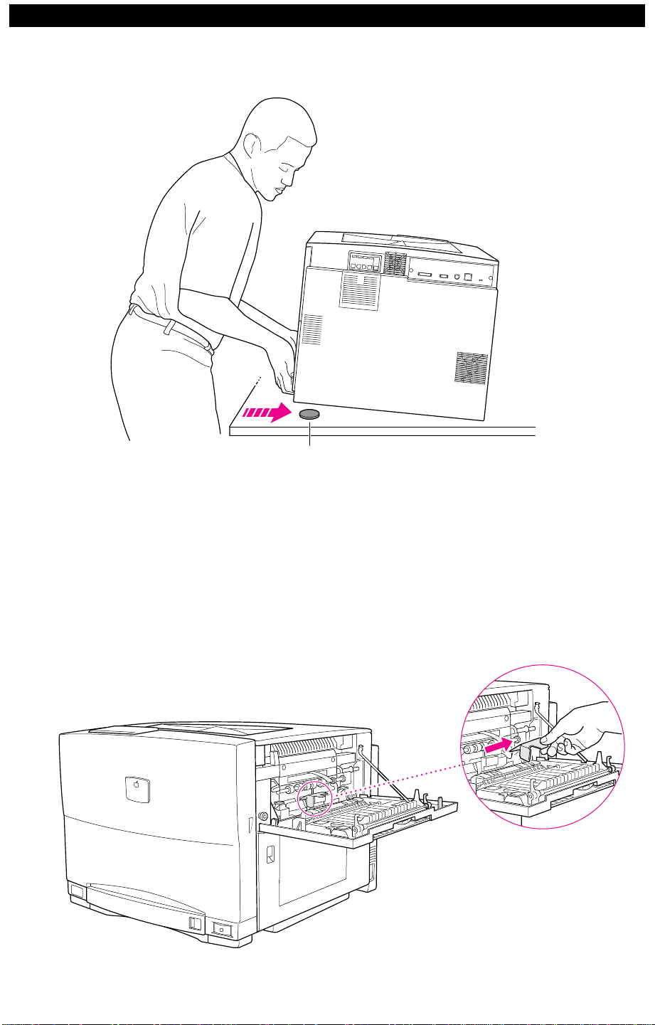
3 Place the shims under the printer’s feet (as needed) to level the
printer.
Shim
The oil absorption sheets have been installed to eliminate
migration of silicon oil during shipping. After leveling the
printer, remove the shipping spacers and absorption sheets as
described below.
1 Open the fuser access door and remove the two orange spacers
and the oil absorption sheet from inside.
96.11.13.15.58
Page 7
Color LaserWriter 12/660 PS 3–4
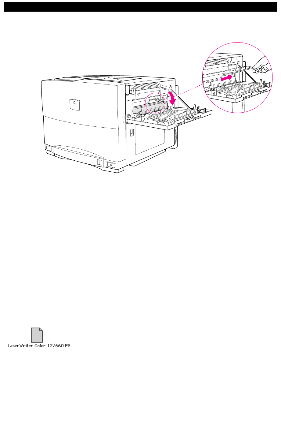
2 Open the fuser assembly and remove the oil absorption sheet
from the inside of the fuser assembly.
I/O Controller Board Changes
Driver Software
The Color LaserWriter 12/660 PS comes standard with 16 MB
of DRAM and version 2.0 of ROM. All other characteristics of
the board remain the same.
Note
: Version 2.0 of ROM contains fixes for variety of system
and networking bugs that have been reported since the release
of the original printer. (I/O controllers with 2.0 ROM will also
output new startup and demo pages). If you want to upgrade an
existing printer, see “Upgrade Path” later in this chapter.
The new version of the Color LaserWriter printer does not
require a driver upgrade. However, the printer name has
changed in ROM. Consequently, with older drivers you must
manually select the “LaserWriter Color 12/600 PS” PPD when
setting up the new printer in the Chooser.
Alternately, if copy the new “LaserWriter Color 12/660 PS”
PPD into the Printer Descriptions folder (path: System
Folder:Extensions folder), Chooser setup will be automatic.
This PPD can be found on the Service Source CD (path:
Service Manuals:Clips:CLW 12/660 PPD).
96.11.13.15.58
Page 8

Color LaserWriter 12/660 PS 3–5
Upgrade Path
You can upgrade a Color LaserWriter 12/600 PS to a Color
LaserWriter 12/660 PS by installing version 2.0 ROMs onto the
customer’s I/O controller board. The version 2.0 R OM upgrade
kit is available as P/N 076-0621. The contains eight ROM ICs,
a user manual addendum, a software installation CD, and
upgrade labels.
Note
: Install new ROM only if the customer’s printer is exhibiting one of the problems described below. Install a replacement I/O controller board (P/N 661-0133) only if your
troubleshooting has found the board to be defective. All service
stock for the I/O controller board will include version 2.0 of
ROM.
After installing the new R OM, affix the labels that are provided
in the kit as described in the instructions that accompany the
ROM upgrade kit.
Feature added in ROM v2.0
System bugs fixes
in ROM v1.2
Caution:
of the ROM also appeared in version 1.2.
All but one of the bug fixes contained in version 2.0
If your I/O
controller board has version 1.2 of ROM, do not upgrade
unless it is specifically for the Windows 95 feature described
immediately below. You can identify the ROM version by
inspecting the margin text on the startup page.
• Plug and play support for Windows 95
Plug and play support means that the user can connect the
printer to the system, boot Windows 95, and automatically see
the printer name in the “New Hardware Found” dialog box
during the installation process. After installation is complete,
the Device ID string and related information will be returned
whenever the printer is queried for its device id.
• System error at address 0x132460
When printing a complex document to the Color LaserWriter
12/600 PS, a page is printed stating “printer restarted due to
system error at address 0x132460.”
• System error at address @0x33F844
A bug in version 1.0 ROM caused certain complex Adobe Illus-
trator files to reset the printer and to print a page stating “printer
restarted due to system error at address @0x33F844.
• Image stitching problem
When an image has a very fine line running across its body and
the line does not seem to belong to the image, that may be a
stitching problem. If the same problem occurs when printing to
another printer, for example a LaserWriter 16/600 PS, the
96.11.13.15.58
Page 9

Color LaserWriter 12/660 PS 3–6
problem is likely in the application and the ROM upgrade will
not help.
If possible, try printing the problem file to a printer with version
2.0 ROMs. If there is no improvement, then the problem is
elsewhere.
• NetWare port number not set properly
When setting the NetWare port number through the Apple
Printer Utility, the number did not stick.
• Changing AppleTalk type fails
Changing the AppleTalk “type” on version 1.0 ROMs fails
when PAPTest is run through a LocalTalk port. (Unlikely to
affect normal user).
• EtherTalkZone and LocalTalkType strings
EtherTalkZone strings and LocalTalkType strings did not take
input longer than 31 characters. (Unlikely to affect normal
user).
• LocalTalk ports turns off; EtherTalk remains active
In some cases, the LocalTalk port turned off after printing a
very large number of PostScript test files to a printer using both
EtherTalk & LocalTalk ports, even though the EtherTalk port
remained active and could be seen from any host. (Unlikely to
affect normal user).
• Specific PostScript Code resets printer
Sending the following PostScript code caused the printer to
reset itself (unlikely to affect normal user):
[(%disk1%) <</InitializeAction 1>> setdevparams]
• PowerPoint v3.0 gradients
Some PowerPoint slides containing complex gradients or
patterns would freeze the printer.
• TraySwitch not saved
Enabling the TraySwitch feature on a Color LaserWriter
12/600-J (Kanji version) did not survive power cycles.
• One-byte PostScript filename on printer hard drive
Creating a one-byte long PostScript filename on a printer’s hard
disk caused an I/O error. (Unlikely to affect normal user).
• Configuration switch and image data
This issue only affects printing from PC computers using the
parallel port. Once the printer’s configuration switch w as used,
96.11.13.15.58
Page 10

Color LaserWriter 12/660 PS 3–7
the default protocol for the parallel port (TBCP) was changed
to Normal and not returned back to TBCP, regardless of configuration switch position. In this scenario text documents would
print, but documents with images (binary data) would not. The
printer’s ready light would flash for a while, stop, and then
nothing would print.
Networking bugs
fixes in ROM v1.2
• NetWare polling
If the printer was in NetWare PServer mode configuration, it
would likely stop polling its NetWare print queue after being
powered on for more than 24 hours.
• Name lengths increased
The pserver and rprinter name length has been increased to 47
characters maximum.
96.11.13.15.58
Page 11

Color LaserWriter 12/660 PS 3–8
Installation Reimbursement Program
Beginning October 21, 1996, Authorized Apple Resellers and
institutions are entitled to receive a $150 reimb ursement on the
installation(s) of the Color Laserwriter 12/660 PS.
Customers who purchase the printer beginning October 21,
1996 are entitled to have the printer set up and installed in the
location of their choice at their site.
How customers will be informed
A letter will be included with the printer informing customers
to contact their Authorized Apple reseller, or Apple directly to
perform the installation.
This letter also stipulates special tasks for the customer to
perform before a service technician arrives at their location.
These tasks include:
• Preparing a suitable location for the printer.
• Having someone available to help the service technician lift
the printer from the floor to the table or counter.
• Providing appropriate power, networking connections, and
cabling.
• Ensuring that a network administrator (or other knowledge-
able person) is available for consultation with the service
technician.
• Providing a computer that is configured with the appropriate
system software and is functioning on the network.
• Arranging for the storage and disposal of packing materials.
Installation procedures
If everything is prepared, the service technician should be able
to complete the setup and installation in about 45 minutes.
The file “CLW 12/660 Setup.pdf” is the first chapter of the
Color LaserWriter 12/660 PS. Read this chapter for the special
considerations required when setting up and installing this
printer. Click on the icon below to open the file.
96.11.13.15.58
Page 12

1
Basics and Theory
Page 13

Color LaserWriter 12/600 PS Basics & Theory 1–2
Chapter Contents
I General Information
Features ......................................................................................................... 1–5
Specifications..................................................................................................1– 6
Safety Information ..........................................................................................1–10
Laser Safety ..............................................................................................1–10
Toner Safety .............................................................................................. 1–10
Ozone Safety ............................................................................................ 1–10
Status Panel ................................................................................................... 1–11
Outline .......................................................................................................1–11
Configurations ...........................................................................................1–12
Density Control Panel ....................................................................................1–13
Panel Layout .............................................................................................1–13
Density Adjustments .................................................................................1–14
Test Page Pattern Selection.......................................................................1–15
Separation Voltage Designation ................................................................1–16
Registration Adjustments........................................................................... 1–17
II Basic Operation
Paper Path Animation..................................................................................... 1–19
Functions ........................................................................................................1–20
Outline of Electrical System ........................................................................... 1–21
Outline of Major Circuit Boards ...................................................................... 1–22
DC Controller Input/Output Signals ...........................................................1–23
Mechanical Controller Board Input/Output Signals ...................................1–26
Outline of Drive System .................................................................................1–28
III Laser/Scanner System
Laser System ................................................................................................. 1–32
Scanner System ............................................................................................. 1–38
IV Image Formation System
Outline ............................................................................................................1–41
Photoconductor Cartridge .............................................................................. 1–43
Toner Cartridge ..............................................................................................1–44
Stages of Imaging .......................................................................................... 1–47
Stage 1: Electrostatic Latent Image Formation ........................................1–48
Stage 2: Developing .................................................................................1–50
Stage 3: Photosensitive Drum Cleaning .................................................. 1–51
Stage 4: Transfer ..................................................................................... 1–53
Stage 5: Transfer Drum Cleaning and Discharge ....................................1–57
Stage 6: Fusing ........................................................................................1–59
High-Voltage Control ...................................................................................... 1–60
Photosensitive Drum Life Detection ...............................................................1–68
Toner Carousel Control ..................................................................................1–71
Toner Cartridge Installation .......................................................................1–73
Carousel Rotation...................................................................................... 1–75
Toner Cartridge Stop.................................................................................. 1–79
Toner Cartridge Press ...............................................................................1–80
Developing Cylinder Drive ........................................................................1–81
Toner Cartridge Separation ....................................................................... 1–82
Image Quality Stability Control ....................................................................... 1–84
Temperature/Humidity Sensing System .................................................... 1–85
Density Calibration System .......................................................................1–86
95.08.23.11.28
Page 14

Color LaserWriter 12/600 PS Basics & Theory 1–3
V Pickup/Feed System
Outline ............................................................................................................1–89
Paper Pickup .................................................................................................. 1–90
Overhead Transparency Detection ................................................................1–96
Cassette Pickup Board ...................................................................................1–97
Transfer Drum and Peripherals ......................................................................1–100
Gripper Control .........................................................................................1–102
Attraction Roller ........................................................................................1–103
Separation .................................................................................................1–105
Transfer Drum Cleaning Assembly ...........................................................1–106
Discharge Roller .......................................................................................1–107
Cleaning Brush Motor Drive Circuit ...........................................................1–109
Fuser Assembly .............................................................................................. 1–110
Transparency Mode ..................................................................................1–112
Fuser Assembly Errors ..............................................................................1–115
Oil Circulation System ...............................................................................1–122
Fuser Cleaner Assembly ...........................................................................1–124
Main Motor Drive Circuit .................................................................................1–125
Paper Jam Detection ......................................................................................1–126
Pickup Delay Jam ..................................................................................... 1–127
Paper Top Position Delay Jam .................................................................. 1–128
Grip Jam ...................................................................................................1–129
Separation Delay Jam ...............................................................................1–130
Separation Stationary Jam ........................................................................1–131
Delivery Delay Jam ...................................................................................1–132
Delivery Stationary Jam ............................................................................1–133
Multi-Fed Paper Stationary Jam ...............................................................1–134
Non-Dedicated Transparency Jam ...........................................................1–135
Wrong Paper Length Feed Jam ................................................................1–136
Initial Residual Jam ...................................................................................1–137
VI System Interface
Outline ............................................................................................................1–139
Video Interface ...............................................................................................1–140
VII Power Supply
Outline ............................................................................................................1–143
Remote Switch ...............................................................................................1–145
VIIISheet Feeder
Outline of Electrical Circuit .............................................................................1–147
Sheet Feeder Controller Board Input/Output .................................................1–148
Pickup/Feed System ...................................................................................... 1–149
Power Supply .................................................................................................1–150
95.08.23.11.28
Page 15

Color LaserWriter 12/600 PS Basics & Theory 1–4
I. General Information
Page 16

Color LaserWriter 12/600 PS Basics & Theory 1–5
Features
Some of the main features of the Color LaserWriter 12/600 PS are as
follows:
Print Quality
Speed
Multiplatform
Support
Connectivity
Automatic
Traffic Control
Fonts
Energy
Savings
Hard Disk
Option
The printer has a resolution of 600x600 dots per inch, with color PhotoGrade.
The printer prints up to 12 pages per minute in black, cyan, magenta, or
yellow; 3 pages per minute in two or more colors; and 1 transparency
per minute.
You can connect the printer to Macintosh, Windows, DOS, and UNIX
computers.
The printer offers LocalTalk, Ethernet, and parallel connections.
Without any user intervention, the printer can accept jobs simulta-
neously from AppleTalk, TCP/IP, and NetWare networks and from the
parallel port.
The printer supports both TrueType and PostScript fonts. The printer
has 39 built-in PostScript fonts.
The printer can automatically lower its power consumption when it’s
not being used.
You can install an internal hard disk or attach up to six external hard
disks to store downloadable fonts.
Paper Handling
You can print up to 350 sheets (250 in the standard paper cassette plus
100 in the multipurpose tray) without changing paper. You can also add
a 250-sheet feeder.
95.08.23.11.28
Page 17

Color LaserWriter 12/600 PS Basics & Theory 1–6
Specifications
Marking
Engine
Laser
Controller
Canon HX LBP print engine
• 3 ppm in color; 12 ppm in black, cyan, magenta, or yellow; 1 ppm
for transparencies
• 600x600 dpi with Color PhotoGrade
• Enhanced 600 dpi grayscale imaging (effective 200-line screen half-
tone, 122 gray levels)
Semiconductor laser GaAlAs
• Wavelength: 780 nm
• Output power: 1 mW
The specifications for the I/O controller board are as follows:
• AMD Am29030 30-MHz microprocessor
• 8 MB of ROM (including 39 Type 1 fonts)
• 12 MB of RAM (16 MB on CLW 12/660); 8 MB soldered + 4 MB
(or 8 MB) SIMM
(expandable to 40 MB total)
• 128 K parameter SRAM
True 600 dpi
• SCSI interface for internal/external hard disk(s)
• LocalTalk interface
• High-speed parallel interface (IEEE P1284 ECP, bidirectional)
• Ethernet interface with three protocols: EtherTalk, Novell NetWare
IPX (PSERVER or RPRINTER), and TCP/IP (BSD lpd)
• External Ethernet transceivers a vailable for thin coaxial, twisted pair
(10Base-T), and thick coaxial (IEEE 802.3 AUI)
• Two-position communication configuration switch
• All ports/protocols simultaneously active
• Color-rendering acceleration
• Data compression/decompression system
• Adobe PostScript Level 2 (version 2014)
The Color LaserWriter 12/600 PS is a true 600 dpi printer because
every aspect of its architecture is designed to a 600 dpi specification. In
addition, its 8-bit per pixel capability can assign levels of color or gray
to each pixel, thereby further enhancing print quality.
96.09.11.09.27
Page 18

Color LaserWriter 12/600 PS Basics & Theory 1–7
Printer Fonts
The following fonts are resident in the printer ROM:
• AvantGarde Book, AvantGarde BookOblique, AvantGarde Demi,
AvantGarde DemiOblique
• Bookman Demi, Bookman DemiItalic, Bookman Light, Bookman
LightItalic
• Courier, Courier Bold, Courier BoldOblique, Courier Oblique
• Helvetica, Helvetica Bold, Helvetica BoldOblique, Helvetica
Narrow, Helvetica Narrow Bold, Helvetica Narrow BoldOblique,
Helvetica Narrow Oblique, Helvetica Oblique
• Helvetica Condensed, Helvetica Condensed Bold, Helvetica
Condensed BoldOblique, Helvetica Condensed Oblique
• NewCentury Schoolbook Bold, NewCentury Schoolbook Bold-
Italic, NewCentury Schoolbook Italic, NewCentury Schoolbook
Roman
• Palatino Bold, Palatino BoldItalic, Palatino Italic, Palatino Roman
• Symbol
• Times Bold, Times BoldItalic, Times Italic, Times Roman
Life
Expectancies
• Zapf Chancery MediumItalic
• Zapf Dingbats
Minimum life expectancy for the printer is 5 years or 300,000 pages in
black and white or 150,000 color pages, with no monthly page limit.
Recommended maintenance interval is 60,000 pages due to wear on
fuser and rollers.
Toner Cartridge: 4,000 pages per color when printing documents with
average page coverage of 5%.
Photoconductor cartridge: 40,000 pages black and white or 10,000
pages color (for continuous printing); 13,000 pages black and white or
6,500 pages color (printing only single-page documents).
Fuser oil life: 10,000 pages
Fuser assembly life: 60,000 pages
Transfer drum cleaner life: 60,000 pages
Ozone filter life: 60,000 pages
Air filter life: 60,000 pages
Separation Discharge Assembly life: 60,000 pages
95.08.23.11.28
Page 19

Color LaserWriter 12/600 PS Basics & Theory 1–8
Speed
Printing
Materials
Transparencies
Paper Sizes
and Capacity
Suggested
Paper Brands
Prints 12 pages per minute in monochrome; 3 pages per minute
maximum in color; and 1 page per minute for transparencies. Actual
speed depends on the images printed and paper size.
Uses 16- to 28-pound laser-quality bond (60 to 90 g/m2). Most textured
and colored stock is accepted but discouraged, as it will adversely
affect color print quality.
The paper used should not scorch, melt, transfer material, or release
°
hazardous emissions when heated to 200
C (392° F) for 0.1 seconds.
Use only Apple Color LaserWriter 12/600 PS Transparencies A4 or
Letter.
Supports U.S. letter and A4 in the standard paper cassette. The paper
2
cassette holds 250 sheets of 20-pound (75 g/m
) paper. The multipurpose tray can hold up to 100 sheets of standard U.S. letter paper, and
other paper sizes up to U.S. legal. Optional 250-sheet universal
cassettes are available that support letter, A4, B5, and U.S. legal paper
sizes. Cassettes are compatible with both the printer and the optional
sheet feeder.
Apple has tested the following papers and found them to be acceptable.
• Aussydat-lay (A4, France) 100 g/m
2
• Boise Cascade Laser, 20 and 24 pound
• Classic Crest, 24 pound
• Hammermill Laser Print, 24 pound
• Legacy Laser Paper, 24 pound
• Nekoosa Laser 1000, 24 pound
• Neusiedler (A4, Austria) 100 g/m
2
• Xerox 4024 (LTR and A4), 20, 24, and 28 pound
• Nekoosa Laser 1000, 24 pound
Note
: Recycled paper is not recommended. It tends to produce more
paper dust, degrading image quality and necessitating more frequent
replacement of the fuser assembly.
95.08.23.11.28
Page 20

Color LaserWriter 12/600 PS Basics & Theory 1–9
Dimensions
Weight
Environmental
Conditions
Acoustic
Output
Wait Times
Voltage
Requirements
Power
Consumption
Height: 18 in. (46 cm)
Width: 21 in. (54 cm)
Depth: 23 in. (58 cm)
Approximately 110 lb. (50 kg) for the printer body only
During printer operation: Temperature 50° to 86° F (10° to 30° C) and
humidity 20 to 80 percent RH noncondensing (for optimum print
quality, operate at 35 to 70 percent RH)
°
In storage (both toner cartridges and printer): Temperature –4
°
F (–20
to 40° C) and humidity 10 to 95 percent RH noncondensing
to 104°
Standby, less than 45 dB
Printing, less than 55 dB
• Either 120 or 240 V, 3.5 minutes maximum
• Either 100 or 220 V, 4.5 minutes maximum
100 to 120 V (50/60 Hz) or 220 to 240 V (50 Hz), voltage tolerance
plus or minus 10%
Energy-saving mode
• Approximately 42 W (meets EPA Energy Star)
Standby average
• 100/120 V, approximately 215 W
• 220/240 V, approximately 238 W
Operating average
• 100/120 V, approximately 535 W
• 220/240 V, approximately 524 W
Maximum power consumption
• 100/120 V, approximately 1.1 KW
• 220/240 V, approximately 1.0 KW
95.08.23.11.28
Page 21
Color LaserWriter 12/600 PS Basics & Theory 1–10
Safety Information
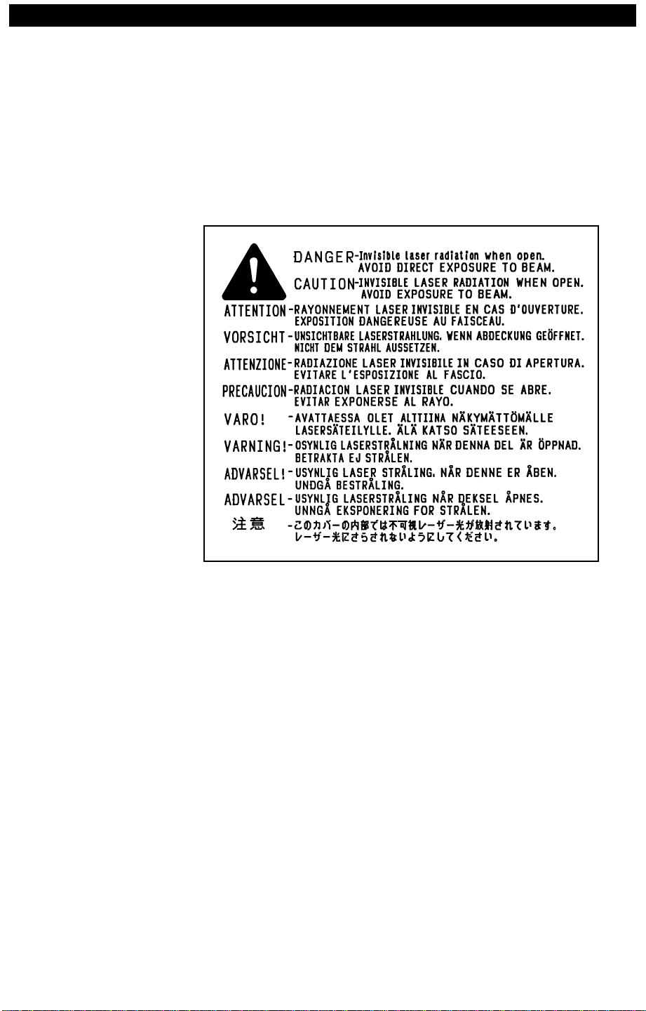
Laser Safety
The invisible laser beam irradiated within the laser/scanner assembly
can be harmful if it comes into contact with your eyes. Consequently,
never disassemble the laser/scanner assembly. A cautionary label has
been affixed to the top of the laser/scanner assembly.
Note
: The laser/scanner assembly cannot be adjusted in the field, nor
are any of its components available from Apple.
Toner Safety
Ozone Safety
Laser Safety Label
If you get toner on your skin or clothes, remove as much as possible
with dry tissue and then wash with cold water. Do not let toner come
into contact with vinyl material.
The charging roller and separation discharge assembly generate very
small amounts of ozone gas when the printer is operating. The printer
meets the Underwriters Laboratory (UL) ozone emission standard.
95.08.23.11.28
Page 22
Color LaserWriter 12/600 PS Basics & Theory 1–11
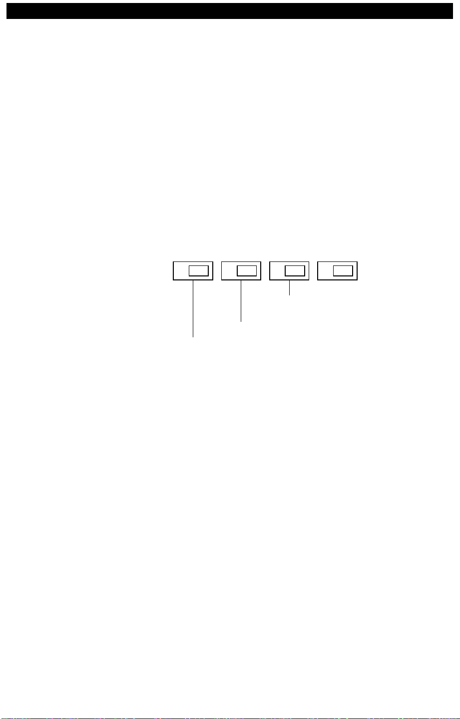
Status Panel
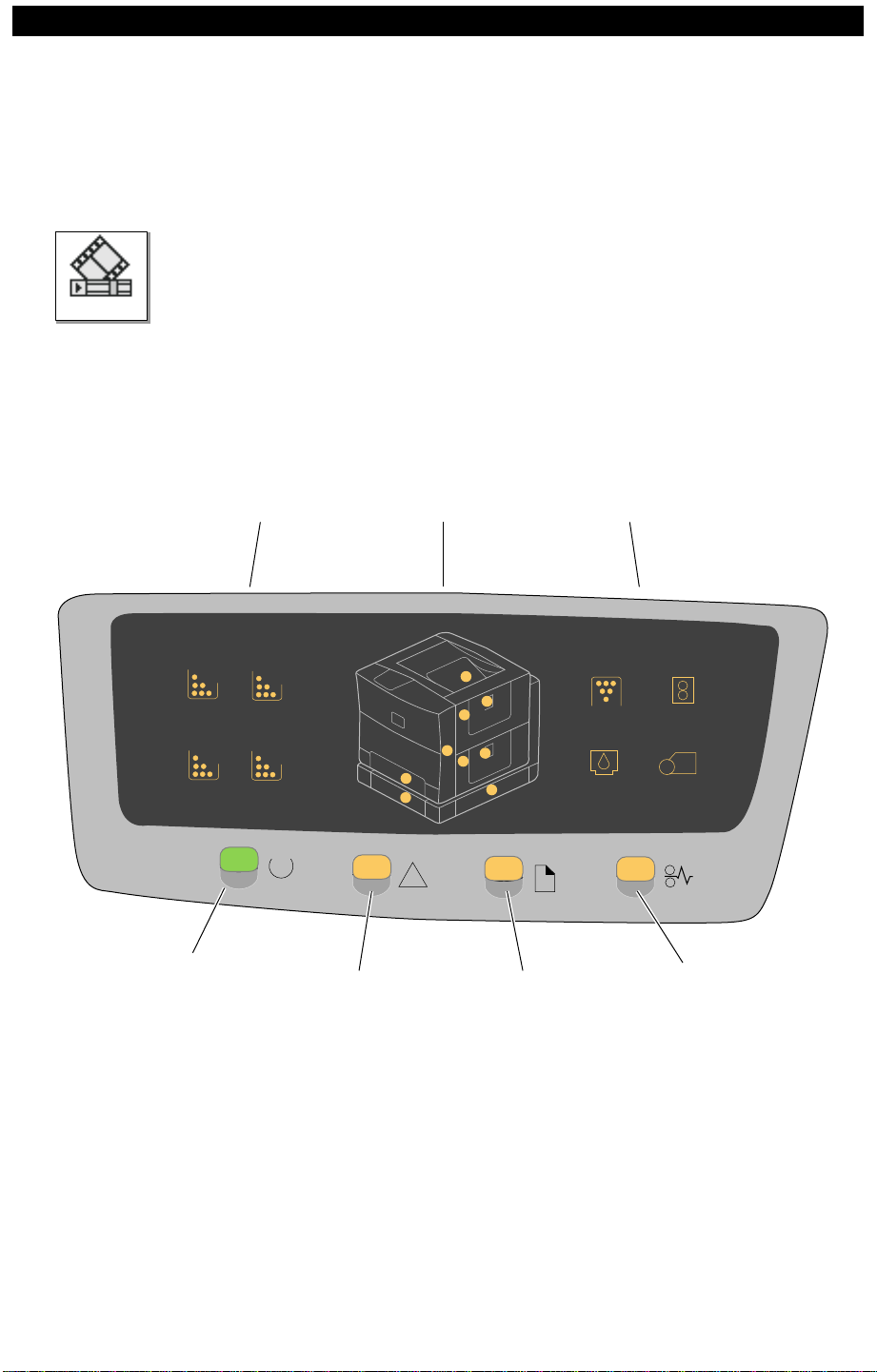
Outline
Movie
The Color LaserWriter 12/600 PS status panel consists of 4 primary and
17 secondary lights. The primary lights, arranged horizontally along
the bottom of the panel, are similar to those on the LED panels on many
of Apple’s previous printers.
During normal operation, primary lights report general readiness states
for consumables, paper supply , and paper feed. Secondary lights report
on specific consumables and highlight locations of a consumable, paper
jam, or paper problems. The QuickTime movie to the left shows the
normal operational behavior of the status panel when the printer starts
up. See Chapter 2 for information on the Power-On Self Test (POST).
Access Lights Maintenance LightsToner Lights
MC
Waste
Toner
Fuser
Assembly
Bk
Ready/In-Use
Light
Y
Oil Photo-
conductor
!
Alert
Light
Paper-Out
Light
Paper Jam
Light
95.08.23.11.28
Page 23
Color LaserWriter 12/600 PS Basics & Theory 1–12
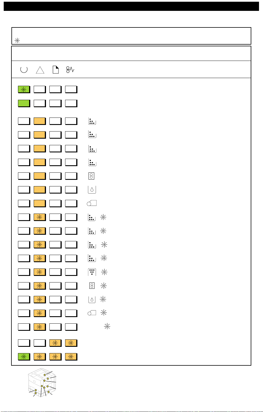
= Flashing
Status Panel Lights
These are the possible arrays that customers can see during normal printer operation.
!
M
C
Y
Bk
Description
Warming Up /Processing
Printer Ready
Low Magenta
Low Cyan
Low Yellow
Low Black
Low Fuser Assembly
Low Fuser Oil
Printer
Stops
No
No
No
No
500 pages later
50 pages later
M
C
Y
Bk
Access
Lights
Photoconductor Warning
No Magenta Cartridge
No Cyan Cartridge
No Yellow Cartridge
No Black Cartridge
Toner Disposal Box Full
No Fuser Assembly
No Fuser Oil
No Photoconductor Cartridge
Door Open
(See "POST Code Matrix" in Chapter 2)
No
Yes
Yes
Yes
Yes
Yes
Yes
Yes
Yes
Yes
Yes
1
2
3
4
9
6
8
7
Access Lights
5
95.08.23.11.29
Page 24
Color LaserWriter 12/600 PS Basics & Theory 1–13
Density Control Panel
The density control panel on the rear of the printer can be used to
generate a service test page and to set three distinct types of adjustments. Some adjustment settings are persistent (i.e., they will remain in
effect after a printer restart), and some are nonpersistent (i.e., they will
default to factory setting after a printer restart).
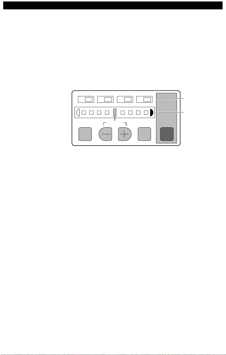
Panel Layout
In addition to the test print button, the density control panel has four
toner-indicator lights along the top, an LED density gauge in the
middle, and four input buttons along the bottom of the panel.
Toner
Lights
Density
Gauge
TEST PRINT
•
Important
M C Y Bk
COLOR
SELECT
DEFAULT ENTER
TEST
PRINT
button: Press this button to generate a service test page.
: If the printer is in energy-saving mode, you must print to
the printer or restart the printer before you can run a service test page.
•
ENTER
Note
button: Engages the currently selected value.
: The next four items are labelled on the panel according to their
density adjustment functions. During other adjustments, ignore the
labels and the functions described below.
COLOR SELECT
•
button: Selects the color whose density you want to
adjust.
• Density gauge: Indicates the currently selected density value for the
selected color, light density to the left, dark to the right.
Note
: During printer-ready state, you can tell if the density settings are
not at the factory default by looking at the center density gauge LED
above the word
DEFAULT
. If this LED is off, then the density settings
have been changed from the default.
5 Plus/minus (+/-) buttons: Advance the density gauge setting.
6 Toner Lights: An illuminated toner light indicates the color that is
being adjusted.
95.08.23.16.19
Page 25
Color LaserWriter 12/600 PS Basics & Theory 1–14
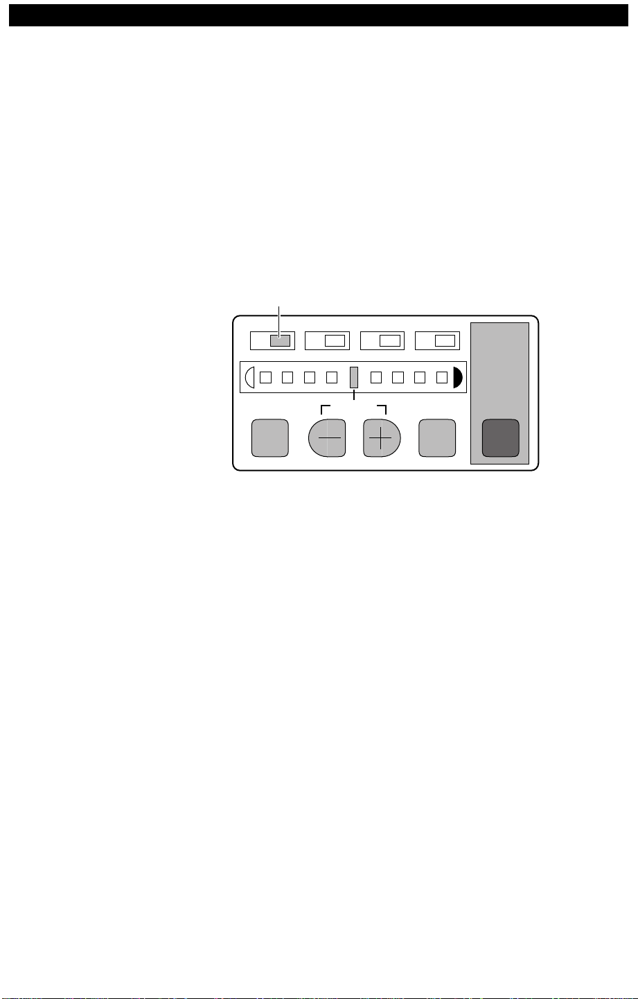
Density
Adjustments
This feature is offered for customers who have multiple Color LaserWriter 12/600 PS printers in a single location and need to adjust one
printer to match the output of another.
Important
: The range of settings is limited. Use this feature only if
you have prior experience in four-color density adjustments.
The printer needs to be switched on and in a ready state to make density
adjustments. Density adjustments are persistent. To adjust the density,
1 Press the
COLOR SELECT
button as many times as necessary until the
desired toner light illuminates.
Selected Color
M C Y Bk
COLOR
SELECT
DEFAULT ENTER
TEST
PRINT
2 Press the plus or minus button to change the setting for that color. The
density gauge LED will light whenever the selected setting differs from
the previously entered setting.
3 Repeat steps 1 and 2 if you want to adjust other colors.
4 Press the
Note
: If you want to quickly return the printer to its factory defaults,
ENTER
button to engage the settings.
press and hold both the plus and minus buttons for at least five seconds.
95.08.23.11.29
Page 26
Color LaserWriter 12/600 PS Basics & Theory 1–15
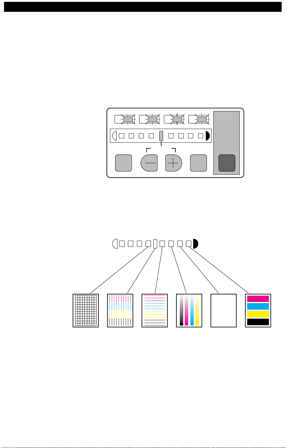
Test Page
Pattern
Selection
This feature allows you to select one of six test page patterns based
upon which one would best confirm a print quality issue.
Test pattern selection is nonpersistent. After restart, the test page
reverts to the vertical line pattern. To select a pattern,
1 Hold down the
COLOR SELECT
button and press the
ENTER
button
eight times. The four toner lights will flash to indicate that you are in
the test pattern selection mode.
M C Y Bk
COLOR
SELECT
DEFAULT ENTER
TEST
PRINT
2 Using the plus or minus buttons, advance the density gauge to illumi-
nate the LED corresponding to the desired pattern. The density gauge
will flash when the selected setting differs from the previously entered
setting. Only LEDs 4 through 9 on the density gauge correspond to
available patterns.
Usage Tips
Grid
3 Press the
Vertical
ENTER
Lines
Lines
GradationHorizontal
Solid
White
button to engage the setting. If you make no further
Solid
Colors
adjustments, the panel will exit from the test pattern selection mode in
30 seconds.
Each pattern will inherently reveal a different type of defect. For
example, color registration problems are revealed best by the grid
pattern, while dirty rollers are revealed by printing a solid white page.
Note
: By measuring the distance between repeating print defects, you
can isolate the problem to a specific roller within the printer. See
“Roller Diameters” in Chapter 2.
95.08.23.11.29
Page 27
Color LaserWriter 12/600 PS Basics & Theory 1–16
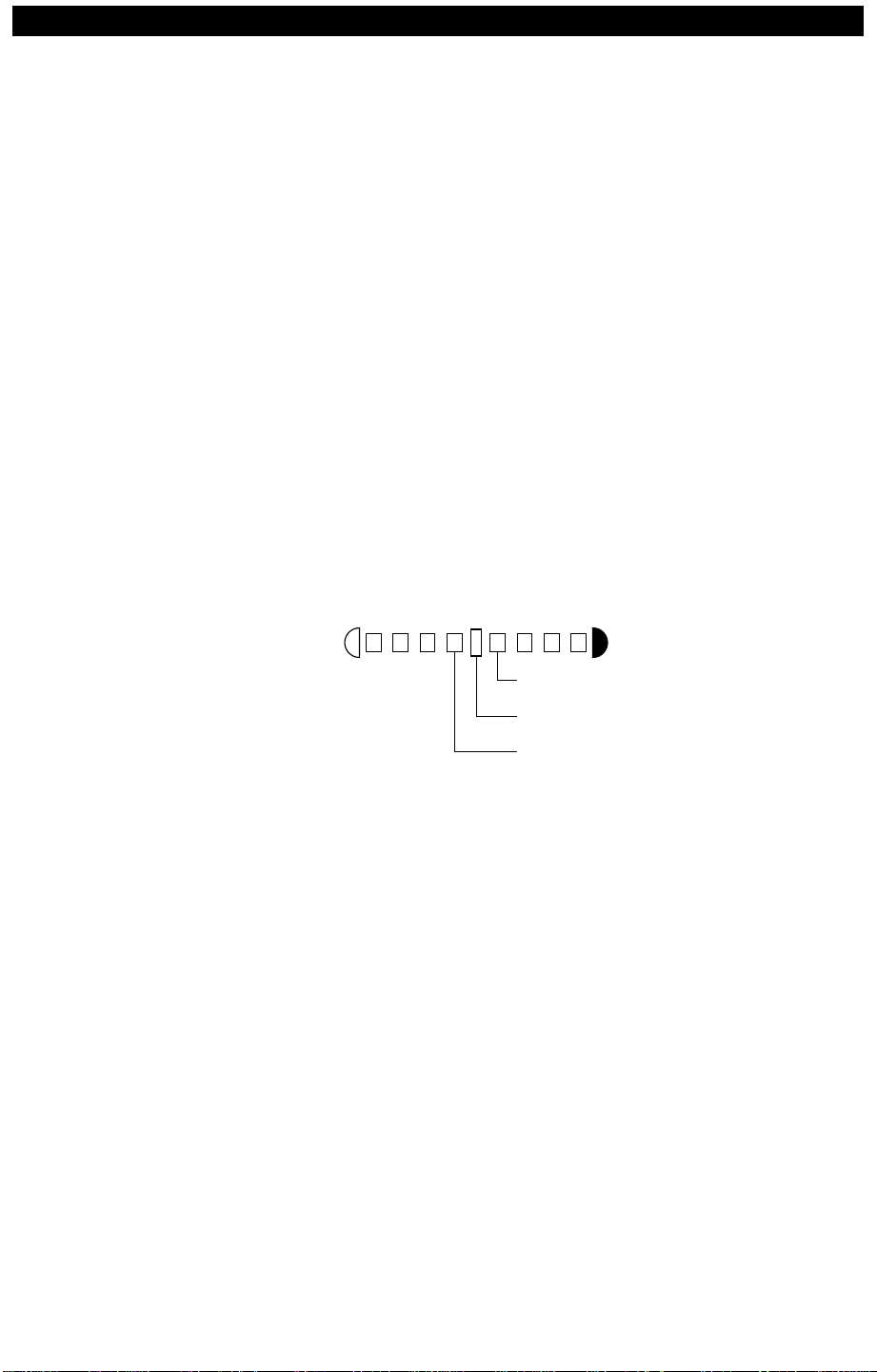
Separation
Voltage
Designation
This feature allows you to override the printer sensing system and force
the separation discharge assembly on or off. Forcing-on is intended as
a fail-safe in low temperature/low humidity conditions where paper is
not properly separating from the transfer drum, and as a countermeasure in some image-offset problems. Forcing-off is a countermeasure
against toner displacement.
The separation voltage designation is nonpersistent. After restart, the
designation will revert to automatic. To designate the separation
voltage,
1 Hold down the
COLOR SELECT button and press the ENTER button
three times. The yellow and black toner lights will flash to indicate that
you are in the separation voltage designation mode.
2 Using the plus or minus buttons, advance the density gauge to illumi-
nate the LED corresponding to the desired designation. The density
gauge will flash whenever the selected setting differs from the previously entered setting. Only LEDs 4, 5, and 6 on the density gauge
correspond to available designations.
3 Press the
Separation Voltage Forced OFF
Automatic (Separation Voltage
Determined by Sensing System)
Separation Voltage Forced ON
ENTER button to engage the setting.
95.08.23.11.29
Page 28
Color LaserWriter 12/600 PS Basics & Theory 1–17
Registration
Adjustments
This feature allows you to adjust the placement of the image area on the
page. Registration adjustments require that the printer be placed into a
service adjustment mode. Consequently, these adjustments are not
designed to be available to end users. Registration adjustments are
persistent. To adjust the registration,
1 Turn off the printer. Press and hold the
TEST PRINT button and switch
the printer back on. The normal startup sounds will not occur.
Continue to hold the
TEST PRINT button down for 25 seconds, at which
time you will notice a slight slowing of the controller fan.
2 Press the
COLOR SELECT button once. The black toner light will flash
to indicate that you are in the service adjustment mode. In addition,
one of the other toner lights will illuminate steadily. Keep pressing the
COLOR SELECT button until you come to the setting that you want.
M C Y Bk
Leading Edge
Registration Adjustment
Cassette Edge Registration Adjustment
Manual Feeding Tray Edge Registration Adjustment
3 Using the plus or minus buttons, advance the density gauge to illumi-
nate the LED corresponding to the desired adjustment value. For
leading edge registration adjustment, each step in the gauge is equal to
.012 inch (.3 mm). For the other two adjustments, each step in the
gauge is equal to .017 inch (.425 mm).
4 Press the
ENTER button to engage the setting.
Note: If you want to quickly return the printer to its factory defaults,
press and hold both the plus and minus buttons for at least five seconds.
95.08.23.11.29
Page 29

Color LaserWriter 12/600 PS Basics & Theory 1–18
II. Basic Operation
Page 30
Color LaserWriter 12/600 PS Basics & Theory 1–19
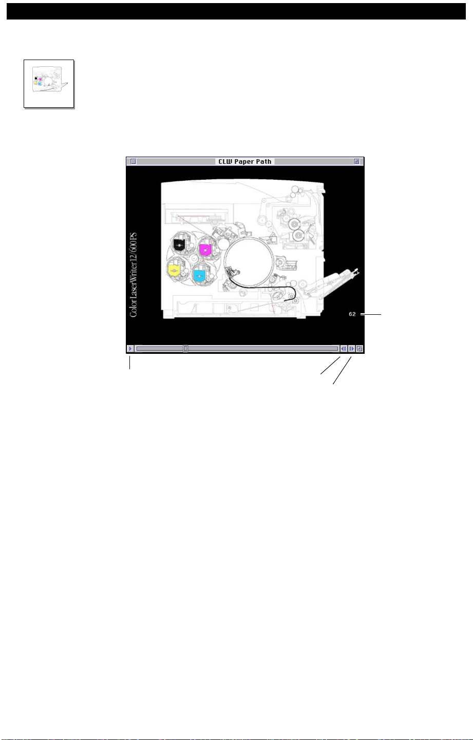
Paper Path Animation
The icon to the left appears at key points throughout this manual.
Clicking it launches a QuickTime animation called “CLW Paper Path.”
Animation
This animation shows one complete print cycle through the Color
LaserWriter 12/600 PS, starting at the point where the final sheet of
paper is picked up from the cassette, and ending with the delivery of the
paper at the top of the printer.
Frame Number
Step BackPlay
Step Forward
The animation is very detailed and moves very quickly. By using the
“Step Back” and “Step Forward” buttons at the bottom right of the
frame, you can step frame-by-frame through the animation. Whenever
applicable, specific frame numbers that best illustrate a given topic are
called out.
95.08.23.11.29
Page 31

Color LaserWriter 12/600 PS Basics & Theory 1–20
Functions
Printer functions can be divided into four systems: the overall control
system, the image formation system, the laser/scanner system, and the
paper pickup/feed system.
I/O Controller Board
I/O Interconnect Board
DC Controller Board
Laser/Scanner Assembly
Scanner
Motor
Laser
Diode
Scanning Mirror
Beam
Position
Detector
Carousel
Primary
Charging
Roller
Toner
Overall Control System
Mechanical Controller Board
Face-Down Tray
Cleaning
Unit
Separation
Discharge
Assembly
Photo-
sensitive
Drum
Transfer Drum
External
Device
Paper Pickup/Feed System
Fuser
Assembly
Transfer
Drum
Cleaning
Assembly
To
Face-
Up
Delivery
Image Formation System
Attraction Roller
Cassette
Sheet Feeder (Optional)
Discharge Roller
Pickup
Block
Manual
Feed Tray
95.08.23.11.29
Page 32

Color LaserWriter 12/600 PS Basics & Theory 1–21
Outline of Electrical System
The operation sequence for the printer is controlled by the microcomputers on the DC controller and the mechanical controller boards.
When the printer is turned on and enters the standby state, the microcomputer on the DC controller sends signals for driving the laser diode,
fuser heaters, and other loads in response to the print signal entered
from the I/O controller board. Simultaneously, the microcomputer on
the DC controller sends the print sequence command to the microcomputer on the mechanical controller. Subsequently, the latter microcomputer outputs the signals for driving various loads, including the highvoltage power supply, motors, and solenoids.
External Device
I/O Controller Board
I/O Interconnect Board
Density Sensing Board
Cassette
Size-Sensing
Board
Laser/Scanner Assembly
Scanner Motor
Beam-Detect Board
Laser Driver Board
Various Sensors
Status Panel
Ejection
Sensing
Board
DC Controller
Board
High-Voltage
Power Supply
Mechanical
Controller
Board
Power Supply
Low-Voltage
Power Supply
Primary Charging Roller
Developing Bias
Transfer Charging Roller
Attraction Roller
Discharge Roller
Separation Discharge
Upper Fuser Roller
Pickup Motor
Cassette Pickup Board
Sensors/Solenoids/Clutches
Main Motor
Drum Motor
Toner Carousel Motor
Cleaning Brush Motor
Various Fan Motors
Various Sensor/
Solenoids/Clutches
Temperature/Humidity
Sensor Board
Toner Sensor
Main Switch
AC Drive Circuit
Fuser Heaters (Upper/Lower)
95.08.23.11.29
Page 33

Color LaserWriter 12/600 PS Basics & Theory 1–22
Outline of Major Circuit Boards
This section describes the functions of the DC controller board and the
mechanical controller board. See “Circuit Boards” in the Parts chapter
for additional information.
DC Controller
Board
Mechanical
Controller
Board
This board controls the printer. When the
/PRNT signal is received from
the I/O controller, the DC controller sends the print sequence command
to the mechanical controller, which then starts controlling various
loads. The DC controller also provides
• Laser/scanner control
• Image stabilization control
• Fuser temperature control
• Power-off time measurement
• Various detection functions
• I/O interface control
This board controls various loads in response to signals from the DC
controller board. The mechanical controller returns the status signals to
the DC controller. The mechanical controller controls the cassette
pickup board, the high-voltage power supply, and the sheet feeder
controller board via its serial communications. The mechanical
controller also provides
• Drive of various motors and fan motors
• Control of the toner carousel
• Control of the fuser assembly
• Control of the transfer drum and its peripheral assemblies
• Control of the cassette pickup board, the high-voltage power supply ,
and the sheet feeder controller board
• Toner stirring function, toner-low detection, and toner cartridge
detection
• Photosensitive drum life detection
• Waste toner collection system control
• Energy-saving mode control
95.08.23.11.29
Page 34

Color LaserWriter 12/600 PS Basics & Theory 1–23
DC Controller Input/Output Signals
Laser/Scanner Assembly DC Controller Board
J111-23
Laser
Control
Board
-22
-17
-1,-3,-4,-5,
-6,-7,-13,15
-9
/VDOENB
/LSON
NHD
SCK1
M1 to M8
"L" when video data can be written.
"L" to switch ON the laser diode forcibly.
Reset signal
Clock signal
PWM mode-setting signal
-11
Analog signals are output to control
the laser power.
Voltage is input in proportion to the
laser power.
Video data signals
Laser Diode
J110-7
-5
-11,-13,-15,-17,
-19,-21,-23,-25
-9
LLCNT
PDIN
Dv2 to Dv9
+5V
J102-4
-3
-2
/BDI
"L" when the BD signal is input.
Beam-Detect
Board
J451-1
-2
-3
+24V
J102-10,-11
-6
-8
-9
-5,-7
SCNCLK
/SCNON
/SCNRDY
Reference clock signal
"L" to drive the scanner motor.
"L" when the scanner motor
is rotating normally.
Scanner
Motor
J701-1,-2
-6
-4
-3
-5,-7
Oil-Low Sensor
PS13
Cleaning Belt
Sensor
PS5
Transfer Drum
Top Sensor
PS8
Waste Toner
Sensor
PS12
Cassette
Size-Sensing Switch
CSW3
CSW2
CSW1
J312-1
-2
-3
-4
J61-3
Sensing Switch
J1602-4
-3
-2
-1
J631-3
-1
-2
J41F-1
-3
-2
J631-3
-1
-2
Ejection
SW1601
-1
-2
J106-6
J106-1
J105-13
J1601-1
-5
-4
-3
-2
-11
-12
J107-1
J107-7
-2
-3
-4
-3
-2
-6
-5
-4
OILSNS
LEDON
WEBSNS
+5V
TOPREG
LEDON
TNFUL
/CSIZE3
/CSIZE2
/CSIZE1
"H" when oil runs out.
"L" when the power-saving mode is set.
"H" when the cleaning belt has run out.
"H" switched to "L" when the TOP
position of the transfer drum is detected.
"L" switched to "H" when the
registration position is detected.
"L" when the power-saving mode is set.
"H" when the waste toner is full.
The cassette size and the pulling
operation for the ejector are detected.
95.08.23.11.29
Page 35

Color LaserWriter 12/600 PS Basics & Theory 1–24
DC Controller Board
Power Supply
Power
Switch
SW1
Door
Switch
SW2
Power Supply Control IC
Fuser Abnormality
Detection Circuit
Safety
Circuit
+24V
+5V
Relay
+5V
Mechanical
Controller
Board
J101-6
J112-31
-30
-29
-28
-26
-27
-5
-7
POFF
PCONT
DOPN
FXSTS
SFSNS
/FXROF
/FXENB
/FXUON
/FXLON
"L" when the power
switch is ON.
"L" to turn ON the printer.
"H" when the front door,
pickup door, or fuser access
door is open.
"L" when the fuser assembly
is properly installed;
"H" when improperly
installed; pulse signal when
fuser heater is ON.
"H" when the safety circuit
turns OFF the relay.
"L" to turn OFF the relay.
The fuser heater can be
turned ON when pulses
are output.
"L" to turn ON the upper
fuser heater.
"L" to turn ON the lower
fuser heater.
Thermoswitch
TP1
Thermoswitch
TP2
Fuser Roller
Temperature
Detection
Fuser Assembly
Upper
Fuser Heater
H1
Lower
Fuser Heater
H2
Thermistor
TH
J112-24
J112-22
The voltage decreases
as the fuser roller
THI
temperature increases.
/FXSNS
"L" when the fixing unit
is installed.
95.08.23.11.29
Page 36

Color LaserWriter 12/600 PS Basics & Theory 1–25
DC Controller Board
Temperature/
Humidity Sensor
J73-1
-3,-5
-2
-4
J2005-5
-4
-2
-1,-3
Mechanical
Controller Board
J2007-6
-7
-9
-8,-10
J112-6
-8,-10
-7
HUMSNS
-9
TMPSNS
+5V
Humidity sensor signal
Temperature sensor signal
Density Sensing
Board
Density Control
Panel
J103-14
-3
-5,-6,-7,-8,-9,-10,-11,-12
-13
J114-1 to 8
+24V
+5V
-1
-2
DSNS
/DSEL
Density sensor signal
"H" to enter the color toner
density sensing mode.
"L" to enter the black toner
density sensing mode.
/D0 to /D7
/DENB
-4
LED power control signal
"L" to turn ON the LED.
Serial Communications
95.08.23.11.29
Page 37

Color LaserWriter 12/600 PS Basics & Theory 1–26
Mechanical Controller Board Input/Output Signals
Mechanical Controller Board
High-Voltage Power Supply
Cassette Pickup Board
Toner Carousel Sensors
Toner
PS4
Carousel
Position
Sensor
Toner
PS3
Cartridge
Position
Sensor
CL2
Toner Carousel
Drive Clutch
CL1
Toner Carousel
Brake Clutch
Fuser Assembly
PS10
Oil Overflow
Sensor
J2008
J2002
J2006-4
-6
-5
J2006-1
-3
-2
J2017-4
-3
J2017-2
-1
J2009-12
-14
-13
Serial Communications
Serial Communications
5VSAVE
DEVHP
"H" when a flag is detected.
See "Carousel Rotational Detection" in
this chapter.
5VSAVE
"L" when the toner cartridge is pressed
DEVCAM
against the photosensitive drum.
"H" when the toner cartridge is separated
from the photosensitive drum.
+24V
/DEVON
"L" to turn ON CL2, rotating the toner carousel
"H" to turn OFF CL2, rotating the cartridge sleeve.
+24V
/DEVBRK
"L" to turn ON CL1, braking the toner carousel.
5VSAVE
OILFUL
"H" when oil overflows from oil pan.
Paper Delivery
Sensor
Fuser Assembly
Drive Clutch
Cleaning Belt
Drive Solenoid
Attraction Roller
Press Solenoid
Drum Press
Solenoid
Transfer Drum
Cleaner Press
Solenoid
Discharge Roller
Press Solenoid
PS9
CL4
SL3
SL6
SL7
SL8
SL9
J2009-9
-11
-10
J2011-2
J2009-8
J2014-2
J2014-4
J2014-5
J2014-10
POUT
+24V
-1
/FIXON
+24V
-7
/WEBSL
+24V
-1
/ATTSLON
+24V
-3
/DDSLON
+24V
-6
/TDCSLON
+24V
-9
/DCSLON
5VSAVE
"H" when paper is detected.
"L" to turn ON SL3, rotating the rollers in the fuser
assembly.
"L" to turn ON SL12. This solenoid is used to drive
the cleaning belt.
"L" to turn ON SL6, operating the attraction roller press
cam. SL6 is used to control the pressing/separation
between the attraction roller and the transfer drum.
"L" to turn ON SL7, operating the transfer drum press
cam. SL7 is used to control the pressing/separation
between the photosensitive drum and the transfer drum.
"L" to turn ON SL8, operating the cleaning brush press
cam. SL8 is used to control the pressing/separation
between the cleaning brush and the transfer drum.
"L" to turn ON SL9, operating the discharge roller press
cam. SL9 is used to control the pressing/separation
between the discharge roller and the transfer drum.
95.08.23.11.29
Page 38

Color LaserWriter 12/600 PS Basics & Theory 1–27
Transfer Drum
PS6
Attraction
Sensor
PS8
Transfer Drum
Top Sensor
PS7
Separation
Sensor
Gripper Drive
Solenoid
Separation
Solenoid
SL4
SL5
Receiver Emitter
Toner Sensor PS11
Main Motor
Toner Carousel Motor
Drum Motor
Cleaning Brush Motor
Fuser Fan Motor
DC Controller Board
J105
-3
-11
-8
-4
-10
-5
-2
J112
-20
-19
-18
-4
-17
-16
M2
M3
M4
M5
FM1
J2007
-12
-13
-14
-15
-28
-16
J2007-21
J2017-5
J2013-6
J2016-1
J2015-1
J2014-8
-7
J2012-3
-2
-1
ATTSNS
TOPREG
SEPSNS
TNSNS
+5V
-6
-7
-1
MLOW
-2
/MRDY
-3
/MON
-4
-5
COMA
-2
COMB
-4
/AO
-5
BO
-6
/BO
-8
AO
COMA
-2
COMB
-4
/AO
-5
BO
-6
/BO
-8
AO
/TDCON
FAND1
FANLK1
GRIPON
+24V
SEPON
Mechanical Controller Board
"H" when print paper is rolled
over the transfer drum.
"L" switched to "H" when the transfer
drum reaches the registration position.
"H" switched to "L" when the transfer
drum reaches the TOP position.
"H" when print paper separates
from the transfer drum.
"H" to turn ON SL4, operating the
gripper drive solenoid.
"H" to turn ON SL4, operating the
separation claw.
"L" when there is no toner or cartridge.
/TONLED
"H" to turn ON the LED.
"L" to rotate the main motor at the
normal speed, "H" to operate it at
half speed.
"L" when main motor rotates normally.
"L" to turn ON the main motor.
Toner Carousel Drive Signal
Drum Motor Drive Signal
+24V
"L" to turn ON the cleaning brush motor.
+24VC (0V in the energy-saving mode)
"L" when the fan motor rotates normally.
Main Fan Motor
Controller Fan Motor
FM2
FM3
J2019-3
J2010-3
-2
-1
-2
-1
FAND2
FANLK2
FAND3
FANLK3
+24VC (0V in the power-saving mode)
"L" when the fan motor rotates normally.
Normally 24V. 16V in the
energy-saving mode with the fan
motor rotating at half speed.
"L" when the fan motor rotates
normally.
95.08.23.11.29
Page 39

Color LaserWriter 12/600 PS Basics & Theory 1–28
Outline of Drive System
The printer has six motors: the pickup motor, main motor, drum motor,
toner carousel motor, cleaning brush motor, and scanner motor. See
“Motors/Fans/Heaters” in the Parts chapter for additional information.
Pickup Motor
(M1)
About the
Printer Drive
Assembly
The pickup motor is a two-phase stepping motor in the paper pickup
block and is controlled by the cassette pickup board. The pickup motor
provides mechanical drive to the following parts:
• Cassette pickup roller
• Separation roller
• Registration roller
• Manual feed pickup roller
• Manual feed paper lifting cam
• Feed rollers 1 and 2
The printer drive assembly houses three separate drive trains for main
motor M2, toner carousel motor M3, and drum motor M4. Their
delivery points and destinations are as shown:
23
8
1
7
6
9
5
Main motor (M2) drive train
Fuser assembly
1
Paper delivery assembly (via the delivery drive assembly)
2
Waste toner screw
3
Transfer drum peripherals
4
Toner carousel motor (M3) drive train
Toner carousel rotation
5
Toner cartridge press (via cartridge press drive gear)
6
Developing cylinder rotation (outer gear)
7
Drum motor (M4) drive train
Photosensitive drum (coupling at the center of the gear)
8
Transfer drum
9
4
95.08.23.11.29
Page 40

Color LaserWriter 12/600 PS Basics & Theory 1–29
Main Motor
(M2)
Toner
Carousel Motor
(M3)
The main motor is a DC brushless motor. It is controlled by the CPU
on the mechanical controller board and provides mechanical drive to
the following parts:
• Fuser assembly
–Upper and lower fuser rollers
–Fuser delivery roller
–Oil-applying roller
–Oil pump
• Paper delivery assembly
• Transfer drum peripherals
–Attraction roller press cam
–Transfer drum press cam
–Cleaning brush press cam
–Discharge roller press cam
• Waste toner screw inside the photoconductor cartridge
The main motor itself is not a part of the printer drive assembly but is
available separately as P/N 922-1370.
The toner carousel motor is a two-phase stepping motor controlled by
the toner carousel motor driver (Q2003) on the mechanical controller
board. This motor is part of the printer drive assembly and provides
mechanical drive to the toner carousel.
Drum Motor
(M4)
The drum motor is a two-phase stepping motor controlled by the drum
motor driver (Q2002) on the mechanical controller board. The drum
motor is part of the printer drive assembly. It provides mechanical
drive to the photosensitive drum and to the transfer drum.
Drum Motor M4
Toner Carousel
Motor M3
Cleaning
Brush Motor
(M5)
Position of
Main Motor M2
The cleaning brush motor is a DC motor. It is controlled by the CPU on
the mechanical controller board and provides the mechanical drive that
rotates the transfer drum cleaning brush.
Scanner Motor The scanner motor is a three-phase, eight-pole DC brushless motor with
a built-in hall element. The scanner motor rotates a six-sided mirror that
in turn scans the laser beam, which has been emitted from the laser
diode, in the horizontal scanning direction.
95.08.23.11.29
Page 41

Color LaserWriter 12/600 PS Basics & Theory 1–30
Basic Sequence of Operation
Outline The following table describes the five periods of printer operation. .
Period & Duration Purpose Remarks
WAIT (Wait)
From power-on until the
fuser roller temperature reaches the target
value. This period finishes in about three
minutes at normal room
temperature.
STBY (Standby)
From the end of the
WAIT period until the
/PRINT signal is input
from the I/O controller.
From the end of the
LSTR period until the
/PRNT signal is input
from the I/O controller
or the power switch is
turned off.
INTR (Initial Rotations)
After the /PRNT signal
has been input from the
I/O controller until the
transfer drum rotates
up to the top position
for the first color.
T o warm up the fuser
roller to put the
printer in the standby
state.
To hold the fuser
roller at the target
value to keep the
printer ready to print.
To stabilize the
sensitivity of the
photosensitive drum
in preparation for
printing.
During this period, the
printer checks for
jammed paper and for
availability of all the
toner cartridges. It
also performs image
stabilization and other
tasks.
If the printer stays in
the standby state for
30 minutes or more, it
drives the main motor
for 0.5 second to
rotate the fuser roller,
so that the fuser roller
will not be deformed.
When the scanner
motor reaches the
target speed, the DC
controller sends the
print sequence
command to the
mechanical controller.
PRINT (Print)
From the end of the
INTR period and the
subsequent completion
of transfer until the
transfer drum rotates
up to the registration
position.
LSTR (Last Rotations)
From the end of the
PRINT period until the
main motor stops.
To form an image on
the photosensitive
drum according to
the /VDO signal input
from the I/O
controller and to
transfer the image to
the paper.
To deliver the last
print and to
discharge the
transfer drum.
Cleaning of the
transfer drum occurs
after every 100 prints.
95.08.23.11.29
Page 42

Color LaserWriter 12/600 PS Basics & Theory 1–31
III. Laser/Scanner System
Page 43

Color LaserWriter 12/600 PS Basics & Theory 1–32
Laser System
Outline When the /PRNT signal is sent from the I/O controller, the DC
controller performs Automatic Photoemission Control (APC) to stabilize the intensity of the laser beam. Upon completion of APC, the DC
controller generates 8-bit video data signals (
with the video signals (
VDO0-VDO7) sent by the I/O controller and then
sends them to the PWM-IC in the laser/scanner assembly . According to
the laser drive signal (internal signal in the laser/scanner assembly)
output from the PWM-IC, the laser driver circuit turns the laser diode
on or off to produce the modulated laser beam.
External Device
I/O Controller Board
/TOP/LSYNC
VDO 0-7
DV2-DV9) in accordance
IMCHR
/PRNT
LLCNT
PDIN
M1-M8 Dv2-Dv9 /VDOENB
PWM-IC
Laser Driver
Board
BD Mirror
Collimator
Lens
Reflecting
Mirror
DC Controller Board
/LSON
Cylindrical
Lens
/BDI
/SCNON
Scanner Motor
Scanning Mirror
Focusing Lens
Photosensitive
Drum
BD Board
The modulated laser beam is converted to a parallel beam with the
collimator lens and cylindrical lens, and the beam then strikes the scanning mirror, which is rotating at a constant speed.
The laser beam reflected by the scanning mirror focuses on the photosensitive drum after passing through the focusing lens and being
reflected by the reflecting mirror. Since the scanning mirror rotates at a
constant speed, the laser beam scans at a constant speed across the
photosensitive drum which also rotates at a constant speed. As a result,
a latent image is formed on the photosensitive drum.
Example: The laser beam comes on in frame 62 for the magenta layer .
The scanner mirror projects it right to left off the reflecting mirror,
which projects it downward and to the right onto the surface of the
Animation
photosensitive drum.
95.08.23.11.29
Page 44

Color LaserWriter 12/600 PS Basics & Theory 1–33
Video Data
Processing
The video data supplied by the I/O controller is composed of 8-bit
video signals (
VDO0-VDO7) for each of four colors, M (Magenta), C
(Cyan), Y (Yellow), and K (Black), and the Image Mode Select signal
IMCHR) which is used to set either the text mode (binary mode) or the
(
image mode (halftone mode).
Laser Driver BoardDC Controller Board
IC403
PWM-IC
Laser
Drive
Signal
Laser
Driver Circuit
VDO 0-7
IMCHR
IC111
Line
Memory
IC109
Image
Masking
Halftone
Correction
Dv2 to 9
M 1 to 8
Note: In order to ensure that text and halftone images are each properly
printed out, the printer switches its image mode via the
IMCHR signal
sent by the I/O controller.
In the image data of the printer there is both full-color mode and mono-
chrome mode. In the full-color mode, the I/O controller sends the
video signals in the order of M, C, Y, and K to the DC controller. In the
monochrome mode, it sends the video signals for only a single color.
The video signals (
VDO0-VDO7) and the IMCHR signal sent to the DC
controller by the I/O controller are sent to the gate array (IC109) via
IC111 (line memory). IC109 processes
VDO0-VDO7 to perform the
image masking, halftone correction, etc.
Note: The printer incorporates the halftone correction table in the DC
controller so that the ideal halftone image can be obtained. This allows
the video signals (
corrected and converted to the video data signals (
VDO0-VDO7) sent by the I/O controller to be
DV2-DV9). They are
subsequently output to the laser driver.
The signals are then converted to 8-bit video data signals (
and mode setting signals (
board in the laser/scanner assembly. The
data signals containing halftone information. The
M1-M8) in IC109 and then sent to the PWM
DV2-DV9 signals are video
M1-M8 signals
DV2-DV9)
control the image mode selection, etc. The PWM circuit modulates the
DV2-DV9 signals into PWM signals and sends them as laser drive
signals to the laser driver board.
The printer includes an anti-counterfeiting function whereby a pattern
unique to the printer is invisibly marked on every printout.
95.08.23.11.29
Page 45

Color LaserWriter 12/600 PS Basics & Theory 1–34
Laser Control Circuit
Laser Emission The DC controller generates 8-bit video data signals (
mode setting signals (
with the video signals (
IMCHR) sent by the I/O controller. It sends those signals to the PWM-
(
M1-M8) in the gate array (IC109) in accordance
VDO0-VDO7) and image mode select signal
IC in the laser driver board. Based on the above signals, the PWM-IC
produces laser drive signals with the pulse width corresponding to the
halftone, and then sends them to the laser driver circuit. At this time,
when the forcible laser-on signal (
is “H” and the video-enable signal (
/LSON) sent to the laser driver circuit
/VDOENB) is “L,” the laser driver
board turns the laser diode on in accordance with the laser drive signal.
DC Controller Board
/TOP
/LSYNC
VDO7 to 0
IMCHR
G.A.
(IC109)
Dv2 to 9
M1 to 8
/BDI
Laser Driver
Board
Laser Drive Dignal
BD Board
PWM IC
(IC403)
DV2-DV9) and
LD
PD
CPU
(IC101)
Laser Driver
Circuit
+5V
APCENB
APCLW
APCUP
PD
12VON
APC-IC
(IC103)
/VDOENB
/LSON
LLCNT
PDIN
+12V
Current/Voltage
Conversion Circuit
Switching Circuit
Constant
Current Circuit
Note: The APC-IC monitors the voltage levels of the 5 V and 24 V
power supplies. If both voltage levels exceed the specified value, the
laser driver board uses 12 V power supply produced from the 24 V
power supply.
95.08.23.11.29
Page 46

Color LaserWriter 12/600 PS Basics & Theory 1–35
Laser Intensity
Control
The CPU in the DC controller controls the intensity of the laser beam
by using the
fine control. The APC-IC (IC103) adds the
to produce the laser beam intensity control signal (
APCUP signal for rough control and the APCLW signal for
APCUP and APCLW signals
LLCNT), which is
then output to the laser driver circuit in the laser/scanner assembly. The
CPU performs automatic power control (APC) of the laser diode and
adjusts the
LLCNT signal so that the laser diode will emit the laser beam
at the constant intensity. The APC is composed of initial APC and
between-pages APC.
Initial APC The printer performs the initial APC in the following steps while it is
executing the initial rotations.
1 When the APC enable signal
(/APCENB) goes “L,” the CPU
decreases the output values of the laser power control signals
APCLW and APCUP) to zero. After resetting the laser current, the
(
CPU rotates the scanner motor.
Note: The
/APCENB signal goes “L” when the 5 V and 24 V power
supplies are at the specified voltage.
2 The CPU sets the forcible laser-on signal (
video-enable signal (
the D/A output value of the
/VDOENB) to “L” via the gate array . It changes
APCUP signal and gradually increases
/LSON) to “L” and the
the laser diode current. When the laser current increases, the laser
diode starts emitting the laser beam. The intensity of the laser beam
emitted by the laser diode is detected by the photodiode (PD) and its
output voltage is fed back as the laser power detect signal (
PDIN) to
the APC-IC.
3 The CPU monitors the
PDIN signal. Until its value reaches the spec-
ified value stored in the CPU, step 2 is continued.
4 The between-pages APC described below is subsequently
performed during the remaining period of the initial rotations to
correct the offset from the target value.
5 The CPU sets the
/LSON signal to “H” to complete the initial APC
and then proceeds to the between-pages APC.
95.08.23.11.29
Page 47

Color LaserWriter 12/600 PS Basics & Theory 1–36
BetweenPages APC
Horizontal
Sync Control
Immediately after the initial APC, the printer performs the betweenpages APC for pages and colors. The CPU sets the
/VDOENB signal to
“H” during the unblanking period.
Note: In order to detect the
/BDI signal, the laser diode is turned on
even during the period that it does not scan the laser beam across the
drum. This is referred to as the “unblanking period.”
This causes the laser diode to emit the laser beam at the intensity set
during the initial APC. To ensure that the
value, the
APCLW signal (8-bit) is changed to correct the LLCNT signal
PDIN signal is at the specified
so as to compensate for the offset from the target value.
A small beam-detect (BD) mirror is fixed in the optical path of the laser
beam. Upon reaching the scanning start position, the laser beam is
reflected by the BD mirror to the BD board in the laser/scanner
assembly during the unblanking period. On receiving the laser beam,
the BD board generates the beam detect input signal (
/BDI) and then
sends it to the gate array in the DC controller board. The gate array
produces the horizontal sync signal (
LSYNC) based on the /BDI signal
and then sends it to the I/O controller.
95.08.23.11.29
Page 48

Color LaserWriter 12/600 PS Basics & Theory 1–37
Laser Diode
Emission
Control
The laser driver circuit turns the laser diode on or off in accordance
with the laser drive signal received from the PWM-IC when the videoenable signal (
/VDOENB) is “L” and the forcible laser-on signal (/LSON)
supplied by the DC controller is “H.” The gate array (IC109) applies
left/right and top/bottom margin masking to the video signals (
VDO0) in accordance with the paper size data sent by the I/O controller,
and then sends them as
DV2-DV9 signals to the PWM-IC in the
VDO7-
laser/scanner assembly. The paper size data is supplied to the CPU by
the cassette-size sensing switch for cassette paper feed or by the paper
size specification command issued by the I/O controller for manual
paper feed.
Notes:
1 The shaded area permits writing with the laser beam.
2 Times T1 and T2 vary depending on the paper size.
3 If no paper size is specified by the paper size specification command
from the I/O controller for manual feed, the printer does not recognize the paper width. So the T1 and T2 values are assumed to be
legal size, the maximum paper width for the printer. The CPU determines the actual paper size from the paper length detected by the
paper leading-edge sensor (PS303) when the leading edge of the
paper has passed through PS303. Subsequently, the image is
masked based on the detected paper size.
/LSYNC
Left/Right Margin
Masking Signal
T2
T1
2 mm
2 mm 2 mm
/TOP
Top/Bottom Margin
Masking Signal
8 mm
95.08.23.11.29
T3
Page 49

Color LaserWriter 12/600 PS Basics & Theory 1–38
Scanner System
Outline The scanning mirror is a critical part in the scanner unit. It is mounted
on the scanner motor shaft and rotates with the scanner motor. The
rotation of the scanner motor is controlled by the scanner driver, so that
the laser beam reflected by the scanning mirror scans across the photosensitive drum at a constant speed. When the scanner motor drive signal
/SCNON) and the scanner clock signal (SCNCLK) are sent to the
(
scanner driver by the DC controller, the scanner driver rotates the
scanner motor.
Laser/Scanner Assembly
Scanner
Mirror
Motor
Scanner
Unit
/SCNRDY
/SCNON
/SCNCLK
DC
Controller
Board
95.08.23.11.29
Page 50

Color LaserWriter 12/600 PS Basics & Theory 1–39
Scanner Motor
Circuit
The scanner motor is a three-phase, 8-pole DC brushless motor with a
hall element. It is incorporated in a single unit with the scanner driver
which controls it so that the motor rotates at a constant speed. When
the printer is turned on, the oscillation frequency of the crystal oscillator (X103) is divided by the gate array (IC109) and the resulting
signal is sent as the
/PRNT signal that is sent to the CPU (IC101) on the DC controller goes
“L,” the CPU sets the
SCNCLK signal to the scanner driver. When the
/SCNON signal to “L” via the gate array and
rotates the scanner motor. When the scanner motor reaches the specified
speed, the scanner motor ready signal (
/SCNRDY) goes “L.” The CPU
on the DC controller issues the print sequence command to the CPU on
the mechanical controller when the
CPU on the DC controller monitors the
/SCNRDY signal goes “L.” The
/SCNRDY signal via the gate
array to determine whether or not the scanner motor is rotating at the
specified speed. If the scanner motor fails to reach the specified speed
within 30 seconds after it starts rotation, the CPU will stop it and notify
the I/O controller of this scanner failure.
/PRNT
J108-29
DC Controller Board
Scanner
Driver
CPU
(IC101)
Gate
Array
(IC109)
9
10
148
66
138
X103
+24V
+5V
SCNCLK
/SCNON
/SCNRDY
J102-10
J102-11
J102-6
J102-8
M
J102-9
J102-5
J102-7
95.08.23.11.29
Page 51

Color LaserWriter 12/600 PS Basics & Theory 1–40
IV. Image Formation System
Page 52

Color LaserWriter 12/600 PS Basics & Theory 1–41
Outline
The image formation system is the nucleus of the printer. Its major
components are the photoconductor cartridge, transfer drum, toner
carousel with toner cartridges, and fuser assembly.
Photoconductor Cartridge
Primary Charging Roller
Developing Cylinder
Toner Carousel
Upon receiving the
Photosensitive
Drum
Separation
Discharge
Transfer Drum
Attraction
Roller
Separation
Claw
Discharge Roller
/PRNT signal from the I/O controller, the DC
Fuser
Assembly
Cleaning Brush
controller completes the designated processing and sends the print
sequence command to the mechanical controller. The mechanical
controller drives various motors and the press cams, which transfer
drive throughout the image formation system.
The primary charging roller negatively charges the surface of the
photosensitive drum just before the drum surface is irradiated by the
laser beam. The latent image formed across the photosensitive drum is
made visible by toner from the toner cartridge, and the image is transferred to the paper on the transfer drum. The surface of the photosensitive drum is cleaned to remove residual toner, and the latent imaging
cycle continues.
These steps are taken for each color. The paper is fed onto the transfer
drum and remains there until the transfer process has been completed.
The paper is then separated from the transfer drum and is delivered to
the fuser assembly.
95.08.23.11.29
Page 53

Color LaserWriter 12/600 PS Basics & Theory 1–42
The transfer drum is also cleaned periodically to remove toner.
However, its surface is discharged to eliminate remaining charges. See
“Imaging Stage 4: Transfer Drum Cleaning and Discharge” later in this
chapter.
1st Color
2nd Color
Toner Cartridge
Black
Yellow
Magenta
Black
Cyan
Magenta
Cyan
Cyan
Yellow
Yellow
Photosensitive
Drum
Transfer Drum
Separation
Claw
Paper
Cleaning
Brush
Discharge
Roller
Attraction
Roller
3rd Color
4th Color
Magenta
Yellow
Cyan
Black
Black
Magenta
95.08.23.11.29
Page 54

Color LaserWriter 12/600 PS Basics & Theory 1–43
Photoconductor Cartridge
Outline The photoconductor cartridge comprises the primary charging roller,
photosensitive drum, and cleaner unit.
Cleaner
Charging Roller
Primary
Photosensitive Drum
The external surface of the photosensitive drum is a photoconductive
layer using an organic photoconductor (OPC), and the inner side is an
aluminum substrate. The primary charging roller is formed with rubber
of medium resistance, and operates in coordination with the photosensitive drum.
95.08.23.11.29
Page 55

Color LaserWriter 12/600 PS Basics & Theory 1–44
Toner Cartridge
Outline The toner cartridge includes a toner container with stirring plate, a toner
feed roller, rubber blade, and developing cylinder. The developing
cylinder, toner feed roller, and stirring plate receive rotational drive
through the white toner cartridge drive gear on the photoconductor
drive shaft. Toner carousel motor M3 supplies this drive in sync with
the drive supplied to the photosensitive drum by drum motor M4.
This internal drive train of the toner cartridge engages with the toner
cartridge drive gear only during the “press” position
Note: See “Toner Carousel Control” later in this chapter for full
description of “home,” “stop,” “press,” and “fetch” positions.
Toner
Container
Toner Stirring
Function
Blade
Developing
Cylinder
Stirring Plate
Toner Feed
Roller
The toner cartridge stirring mechanism consists of the stirring plate and
toner feed roller and helps in supplying toner from the toner container
to the developing cylinder. The stirring plate agitates the toner within
the container. The feed roller is responsible for applying a thin layer of
toner onto the developing cylinder.
95.08.23.11.29
Page 56

Color LaserWriter 12/600 PS Basics & Theory 1–45
CartridgePresence
Detection
The printer has cartridge-presence and toner-level detecting functions.
Both these functions are served by toner sensor PS11. Cartridge presence is sensed when the cartridge is in the “stop” position.
When a toner cartridge is in the “stop” position, the LED of toner
sensor PS11 emits lights through a light pipe in the toner carousel.
Each cartridge bay has its own light pipe. The light emitted from the
light pipe is normally blocked by the cartridge and does not reach the
receiving diode of PS11 mounted above the toner carousel.
Toner Sensor PS11 (Receiver)
Toner Cartridge
Toner Sensor PS11 (Emitter)
If the light does reach the receiving diode, the DC controller determines
that no cartridge is installed in that bay and notifies the I/O controller.
Sound: Cartridge-presence sensing occurs after printer startup or
following the actuation of the toner ejection sensor. The controller
rotates the carousel to each of the four stop positions, confirms that a
Sound
cartridge occupies each bay , then continues its startup sequences. Click
the icon to the left for a sound sampling of the carousel during
cartridge-presence sensing.
95.08.23.11.29
Page 57

Color LaserWriter 12/600 PS Basics & Theory 1–46
Toner-Level
Detection
When it presses against the photosensitive drum, the cartridge shifts
just enough so that the light from PS11 aligns with a window in the
bottom of the cartridge. In a totally empty cartridge, the light beam
would shoot through this window, out a second window in the top of
the cartridge, and strike the receiving diode of PS11.
In a normal cartridge, the controller judges level of toner by measuring
the duration that light strikes the receiving diode after the stirring plate
has swept in front of the bottom window. If the duration is longer than
a prescribed value, the DC controller determines that the toner is low
and notifies the I/O controller.
Toner Sensor PS11 (Receiver)
Window
Toner
Animation
Stirring
Plate
Window
Toner Sensor PS11 (Emitter)
Normal Toner-Low
Example: See the cyan cartridge in frame 116 of the animation. This
is the position that a cartridge is in when toner level is detected. This
position is called the “press” position. It is the only position in which
the inner workings of the toner cartridge are mechanically driven. The
cartridge is in the “stop” position in frame 115.
95.08.23.11.29
Page 58

Color LaserWriter 12/600 PS Basics & Theory 1–47
D
Stages of Imaging
The print process is roughly divided into the six stages shown below.
Electrostatic Latent
Image Formation
Delivery
1 Primary Charging
Photosensitive
Drum Cleaning
2 Scanner Exposure
4 Drum Cleaning
Fusing
3 Developing
11 Fusing
eveloping
8 Separation
7 Toner Transfer
Transfer Drum
Cleaning/Discharge
9 Cleaning
6 Attraction
10 Discharge
5 Grip
Registration
Manual
Feed
Transfer
Cassette
Feed
Flow of Paper
Direction of Photosensitive Drum Rotation
95.08.23.11.29
Page 59

Color LaserWriter 12/600 PS Basics & Theory 1–48
Stage 1: Electrostatic Latent Image Formation
This stage consists of two steps, primary charging and scanning exposure. Upon completion of this stage, the points on the drum that are
struck by a laser beam have their charge neutralized, while those points
not struck remain negatively charged. The image that is irradiated onto
the drum in this manner is invisible and is therefore referred to as a
“latent” image.
0
-100
-500
Surface Electric
Potential (V)
Primary
Charging
(Step 1)
Bright
area
Scanning
Exposure
(Step 2)
Dark
area
Transfer
(Step 6)
Time (t)
Primary
Charging
(Step 1)
95.08.23.11.29
Page 60

Color LaserWriter 12/600 PS Basics & Theory 1–49
Step 1:
Primary
Charging
As a preliminary step in forming the latent image, the surface of the
photosensitive drum is uniformly charged with negative potential. The
primary charging is done by directly imparting charges onto the photosensitive drum.
In order to keep uniform the surface potential charged on the surface of
the photosensitive drum, AC bias is superimposed on the primary
charging roller in addition to the DC bias.
The AC bias (current value) varies according to the values sensed for
temperature and humidity to prevent toner from adhering to the
charging roller.
Primary Charging Roller
Photosensitive Drum
AC
Bias
DC
Bias
Step 2:
Scanning
Exposure
When the laser beam is scanned across the photosensitive drum surface,
the charge in the irradiated area is neutralized and becomes an electrostatic latent image. This is known as “write-black” laser imaging.
Laser beam
Nonirradiated
Area
Irradiated
Area
95.08.23.11.29
Page 61

Color LaserWriter 12/600 PS Basics & Theory 1–50
Stage 2: Developing
In this stage, the toner is placed on the electrostatic latent image on the
photosensitive drum, making the image visible.
Step 3:
Developing
The toner used for the printer is a single-component nonmagnetic toner
composed of resin. This toner is unique for its insulating property, and
is charged with negative potential by friction between the rotating
cylinder and blade surface.
The toner comes in four colors: magenta, cyan, yellow and black. Each
is contained in its own toner cartridge. Each toner cartridge is housed
within the toner carousel and is sequentially advanced to the photosensitive drum in line with the rotation of the carousel. See “Carousel
Rotation” later in this chapter.
Blade
Photosensitive
Drum
AC Bias
Developing
Cylinder
Toner Feed RollerStirring Plate
Note: The irradiated areas on the photosensitive drum have a neutral
charge. For sake of clarity, these irradiated areas are shown as plus
signs (+) since their potential is higher than the charge of toner particles
on the developing cylinder.
DC Bias
The laser-beam-irradiated area on the photosensitive drum is higher in
potential than the toner negatively charged on the cylinder. When this
area comes close to the negatively charged toner on the cylinder, the
toner jumps and adheres to the drum surface due to the difference in
potential between the drum surface and the cylinder.
This effect is called toner projection development and makes the electrostatic latent image on the photosensitive drum surface visible.
AC bias is applied to the developing cylinder for ease of projecting
toner to the photosensitive drum surface and in order to improve the
contrast of the output image. DC bias varies in response to density calibration and the operation of the density control panel.
95.08.23.11.29
Page 62

Color LaserWriter 12/600 PS Basics & Theory 1–51
Stage 3: Photosensitive Drum Cleaning
Step 4:
Photosensitive
Drum Cleaning
During the transfer stage, a small amount of toner does not transfer onto
the paper. To prepare for the next imaging cycle, the toner remaining on
the photosensitive drum surface is scraped by the cleaner blade and the
drum is cleaned.
The scraped toner particles are trapped with the sweeper strip and
collected in the toner disposal box by means of the toner transport plate
and the waste toner transport screw . The waste toner transport screw is
driven by the main motor.
Primary Charging Roller
Laser
Photosensitive
Cleaning Blade
Drum
Toner Transport Plate
Waste Toner
Transport Screw
Sweeper Strip
Photosensitive Drum
Waste Toner
Transport Screw
Toner Disposal Box
95.08.23.11.29
Page 63

Color LaserWriter 12/600 PS Basics & Theory 1–52
When the photosensitive drum door opens, the shutter lever is released,
and the waste toner shutter of the photoconductor closes so that the
waste toner is no longer exhausted.
Toner Disposal
Box
Waste
Toner
Outlet
Shutter
Lever
Shutter
Lever
Waste
Toner
Outlet
Shutter
Lever
Opening the disposal
box cover releases the
shutter lever and closes
the waste toner outlet.
Closing the disposal
box cover presses the
shutter lever and opens
the waste toner outlet.
Waste
Toner
Outlet
The waste toner level is detected by the waste toner sensor (PS12)
housed in the disposal box cover assembly. When the waste disposal
box gets full, the DC controller notifies the I/O controller of the waste
toner full condition and stops the printer.
PS12 Receiver PS12 Emitter
Waste Disposal Box
Toner
Waste Toner FullNormal
95.08.23.11.29
Page 64

Color LaserWriter 12/600 PS Basics & Theory 1–53
Stage 4: Transfer
This stage consists of four steps: grip, attraction, transfer, and separation. This stage is where the toner image is mapped from the photosensitive drum onto the paper.
Step 5:
Grip
When the paper reaches the transfer drum, its leading edge is retained
by the gripper so that the paper is retained on the transfer drum
surface. Since the leading edge of the paper is retained by the gripper,
approximately 8 mm of the leading edge cannot be imaged.
Transfer Drum
Transfer Sheet
Paper
Gripper
Example: The leading edge of the paper is gripped in frame 55 of the
animation.
Animation
95.08.23.11.29
Page 65

Color LaserWriter 12/600 PS Basics & Theory 1–54
Step 6:
Attraction
The attraction roller imparts negative charges onto the paper and helps
hold the paper to the transfer drum surface by means of electrostatic
force. The attraction roller presses only for the first color and separates
from the transfer drum upon completion of the transfer operation for
the first color.
Note: If you select “Best” as the print quality mode, the entire sheet
receives the attraction charge prior to any imaging. This assures the
best possible attraction of paper to drum and requires one extra rotation
of the transfer drum.
For monochrome and continuous print operation, the attraction roller is
separated from the transfer drum upon completion of a single-page
transfer, and returns to the drum before the transfer starts for the next
page.
Transfer Sheet
Animation
Transfer Drum
DC Bias
Attraction Roller
(Rotates by Friction)
Paper
DC bias
DC bias is applied to the attraction roller. The value of the DC bias
varies in line with the temperature/humidity sensing system.
Example: The attraction roller presses in frame 59 of the animation
and separates in frame 89 after the trailing edge of the paper passes.
95.08.23.11.29
Page 66

Color LaserWriter 12/600 PS Basics & Theory 1–55
Step 7:
Toner
Transfer
The paper attracted to the transfer drum is transported in correspondence with the rotation of the transfer drum. At this time, positive
charges are applied to the reverse side of the transfer sheet to transfer
the toner from the photosensitive drum to the paper. This process
repeats sequentially for each color (M, C, Y, K).
Photosensitive Drum
Paper
Toner
Transfer Drum
DC bias
Gripper
Transfer Sheet
Elastic Sponge Layer
Aluminum Layer
The transfer drum consists of an internal aluminum cylinder covered
successively by a conductive elastic sponge layer and an external insulating transfer sheet.
DC bias is applied to the transfer drum. The value of the DC bias varies
in line with the temperature/humidity sensing system.
In full-color mode, as the transfer steps proceed with the first color,
second color, and so on, the transfer force weakens due to the increase
in the number of negatively-charged toner particles on the paper. To
counteract this effect, the transfer bias is gradually increased for the
second and subsequent colors.
95.08.23.11.29
Page 67

Color LaserWriter 12/600 PS Basics & Theory 1–56
Step 8:
Separation
Paper is separated from the transfer drum by the gripper and separation
claw. After passing through the separation discharge assembly, the
leading edge of the paper is pushed up by the gripper and the paper is
separated from the transfer drum surface by the separation claw.
AC Bias
DC Bias
Separation
Discharge
Assembly
Paper
Transfer Sheet
Transfer Drum
Gripper
Animation
Paper
Separation
Claw
Transfer Drum
In a low temperature and low humidity environment, the separation
discharge assembly is activated to assist in separating the paper from
the transfer drum.
Note: The separation discharge assembly can be forced on or off
manually by means of the density control panel. See “Separation
Voltage Designation” earlier in this chapter.
Example: The separation claw actuates in frame 232 of the animation.
The paper then separates from the drum and feeds toward the fuser
assembly. The leading edge of the paper trips separation sensor PS7 in
frame 237.
95.08.23.11.29
Page 68

Color LaserWriter 12/600 PS Basics & Theory 1–57
Stage 5: Transfer Drum Cleaning and Discharge
After the page has left the transfer drum, the printer must return the
drum to a clean and electrically neutral state.
Step 9:
Transfer Drum
Cleaning
During density calibration and after some paper jams, unfused toner
may find its way onto the surface of the transfer drum. The transfer
drum cleaning brush is designed to scrape this residual toner off the
transfer drum. This function takes place following density calibration
and following the opening/closing of any of the doors. It also occurs as
a routine maintenance measure after every 100 prints.
Collected toner is deposited in the filter of the transfer drum cleaner.
Cleaning Brush
(Motorized Rotation)
Transfer Drum
Transfer Drum
Cleaning Assembly
Animation
Sound
The cleaning brush is normally separated from the transfer drum.
When the transfer process terminates and the paper leaves the transfer
drum, the cleaning brush makes contact with the drum, cleans the
surface, then separates from the drum.
Note: For more information, see “Transfer Drum Cleaning Assembly”
in the “Pickup/Feed System” section of this chapter.
Example: The transfer drum cleaning assembly presses against the
transfer drum in frame 223 of the animation, just after the trailing edge
of the paper has passed. The assembly separates from the drum in
frame 274. As noted above, this press and separation of the cleaning
drum assembly occurs in this way only once in 100 prints.
Sound: The transfer drum cleaning assembly has a very distinctive
whining type sound. Click the icon to the left to hear a sampling of this
sound.
95.08.23.11.29
Page 69

Color LaserWriter 12/600 PS Basics & Theory 1–58
Step 10:
Discharge
AC bias is applied by the discharge roller to eliminate charges
remaining on the transfer drum surface after the separation of the paper.
The value of the AC bias varies in line with the temperature/humidity
sensing system.
Transfer Drum
Discharge Roller
(Rotates by Friction)
AC Bias
Note: For more information, see “Discharge Roller” in the
“Pickup/Feed System” section of this chapter.
Animation
Example: The discharge roller presses against the transfer drum in
frame 228 of the animation, just after the trailing edge of the paper has
passed. The assembly separates from the drum in frame 280.
95.08.23.11.29
Page 70

Color LaserWriter 12/600 PS Basics & Theory 1–59
Stage 6: Fusing
Step 11:
Fusing
In the transfer stage, the toner image transferred onto the paper adheres
to it only by means of static electricity, and is susceptible to distortion
when touched by hand. To avoid this problem, the fuser assembly fuses
and mixes the paper and the four toners to create a permanent image.
Note: For more information, see “Transfer Drum Cleaning Assembly”
in the “Pickup/Feed System” section of this chapter.
DC Bias
Upper Heater
Upper
Fuser Roller
Toner
Paper
Lower Heater
Lower
Fuser Roller
95.08.23.11.29
Page 71

Color LaserWriter 12/600 PS Basics & Theory 1–60
High-Voltage Control: Outline
The high-voltage power supply of the printer is controlled by the high-
voltage control IC (IC1003). In serial communication with the
mechanical controller, IC1003 applies voltages to the primary char ging
roller, developing cylinder, transfer drum, attraction roller, discharge
roller, separation dischar ge assembly, and upper fuser roller in response
to the instructions from the mechanical controller.
The primary charging roller , the developing cylinder, and the separation
discharge assembly are charged with superimposed DC and AC voltages. The transfer drum is charged with the positive DC voltage. The
attraction roller is charged with negative DC voltage being superimposed onto the transfer voltage. The discharge roller is charged with
AC voltage being superimposed onto the transfer voltage. The separation discharge assembly normally is charged only with DC voltage and
is charged with AC voltage superimposed on DC voltage only in a low
temperature and low humidity environment. The upper fuser roller is
charged with DC voltage.
Developing
Cylinder
AC Voltage
Generation Circuit
DC Voltage
Generation Circuit
Primary Charging
Roller Voltage Circuit
High-Voltage Power
Supply Board
Primary
Charging
Roller
Transfer Drum
AC Bias
Generation Circuit
DC Bias
Generation Circuit
Developing Bias
Generation Circuit
High-Voltage Control (IC 1003)
Separation
Discharge
Assembly
Discharge Roller
Attraction
Roller
Attraction Roller Voltage
Generation Circuit
Discharge Roller Voltage
Generation Circuit
Transfer Roller Voltage
Generation Circuit
Upper Fuser
Roller
High-Voltage
Separation Bd.
AC Voltage
Generation Circuit
DC Voltage
Generation Circuit
Separation Voltage
Generation Circuit
Mechanical Controller Board
DC Controller Board
95.08.23.11.29
Page 72

Color LaserWriter 12/600 PS Basics & Theory 1–61
High-Voltage Control: Operation
When the /PRNT signal sent from the I/O controller goes “L,” and the
print sequence command is entered from the DC controller to the
mechanical controller, the mechanical controller rotates the drum motor
and controls the high-voltage control IC (IC1003) on the high-voltage
power supply board as follows.
Voltage to
Primary
Charging
Roller
The high-voltage control IC (IC 1003) on the high-voltage power
supply board outputs the primary charging DC voltage drive signal
/HV1DC1), primary charging AC voltage drive signal (/HV1AC1),
(
primary charging DC voltage select signal (
AC voltage select signal (
primary charging voltage) (
power supply. The
/HV1DC1 signal and /HV1AC1 signal turn the primary
/HV1AC0), and density adjustment signal (for
/HV1PWM) to control the high-voltage
charging voltage (DC, AC) on or off. The
/HV1DC0), primary charging
/HV1DC0 signal selects the
printing bias or the between-colors bias/between-pages bias.
/HV1AC0 signal switches the primary charging voltage AC current
The
value according to the environment detected by the temperature/humidity sensing system. The output value of the
/HV1PWM signal
remains fixed.
/HV1DC0
OFF
Between-Colors Bias/Between-Pages Bias
AC Current : Low
Print Bias
AC Current : High
/HV1DC1
L
H
H
/HV1AC0
H
L
L
L
/HV1AC1
H
L
H
H
L
L
95.08.23.11.29
Page 73

Color LaserWriter 12/600 PS Basics & Theory 1–62
For the initial rotations, IC1003 sets the
/HV1DC1 signal to “L” and the
/HV1DC0 signal to “L” to apply between-colors bias/between-pages bias
to the primary charging roller. Then, the
/HV1AC1 signal goes “H” so that the primary charging roller is
the
/HV1DC1 signal goes “L” and
charged with the print bias with the primary charging voltage AC bias
and DC bias being superimposed. For between-colors/between-pages,
/HV1AC1 signal is set to “H” and only the DC bias is applied, with
the
the AC bias turned off.
High-Voltage Power Supply
Primary Charging Roller Voltage Generation Circuit
Constant Voltage Circuit
/HV1PWM
/HV1DC0
/HV1DC1
Integral
Circuit
Voltage
Conversion
Circuit
DC Voltage
Circuit
Generation
Voltage
Detection
Circuit
Overlapping
Primary
Charging
Roller
HVFre1
HVFre2
Mechanical Controller Board
IC1003 (High-Voltage Control IC)
/HV1AC1
/HV1AC0
Switching
Circuit
Constant Current
Controller Circuit
Voltage
ON/OFF
Circuit
Sign Train
Circuit
Generation
Voltage
Selection
Circuit
Amplification
Circuit
Current
Detection
Circuit
HVFre 1, 2 are signals of pulses.
AC Voltage
Generation
Circuit
95.08.23.11.29
Page 74

Color LaserWriter 12/600 PS Basics & Theory 1–63
Developing
Bias
When the print sequence starts, the primary charging voltage (AC/DC)
is applied and the toner cartridge is pressed against the photosensitive
drum to rotate the developing cylinder. Then the high-voltage control
IC (IC1003) on the high-voltage power supply board sets the developing bias DC drive signal (
/DEVDC) to “L” and applies the developing
DC bias to the developing cylinder through the developing bias contact
behind the mechanical controller board. After the specified period of
time has elapsed, the developing bias AC drive signal (
/DEVAVE) goes
“L” and the voltage superimposing developing AC bias onto developing DC bias is applied to the developing cylinder.
The developing bias is applied only when the toner cartridge is pressed
against the photosensitive drum. Before the toner cartridge leaves the
drum, the
/DEVDC signal and /DEVAVE signal are set to “H” to turn off
the developing bias.
Note: The rotation of the toner press drive gear actuates a rocker pin
that opens and closes the developing bias contact. This completes the
circuit to the developing cylinder that is shown on the next page. For
more information, see the “T oner Carousel Assembly” topic in the Take
Apart chapter.
Developing
Bias Contact
Rocker Pin
95.08.23.11.29
Page 75

Color LaserWriter 12/600 PS Basics & Theory 1–64
As the density adjustment signal (for the developing bias) (/DEVPWM)
adjusts image density according to density instructions from the
mechanical controller, IC1003 changes the amplitude value of the
developing DC bias and the developing AC bias. The
/DEVPWM signal
varies according to image density correction control and the setting of
the density control panel.
High-Voltage Power Supply
Developing Bias Generation Circuit
HVFre3
HVFre1
Curve
Forming
Circuit
Switching
Circuit
Constant Voltage Circuit
Generation
AC Bias
Circuit
Overlapping
Voltage
Detection
Circuit
/DEVPWM
/DEVAVE
Mechanical Controller Board
IC1003 (High-Voltage Control IC)
/DEVDC
HVFre1
Integral
Circuit
Integral
Circuit
Voltage
ON/OFF
Circuit
Switching
Circuit
Constant Voltage
Detection
DC Bias
Generation
Circuit
HVFre1, 3 are pulse signals.
Regulator
Developing
Cylinder
Voltage
Circuit
95.08.23.11.29
Page 76

Color LaserWriter 12/600 PS Basics & Theory 1–65
Voltage to
Transfer Drum
The transfer drum is charged with print bias and between-colors bias
according to each print sequence.
For print bias, positive voltage is applied to the transfer drum in order
to transfer the toner on the photosensitive drum surface onto the paper.
High-Voltage Power Supply
Attraction Roller Voltage Generation Circuit
/ATRPWM
/HVFre1
/HVATR
/TRPWM
Constant Voltage Circuit
Voltage
Detection
Switch
Circuit
Integral Circuit
Circuit
Attraction Roller
Voltage Generation
Constant Voltage
Circuit
Circuit
Attraction
Roller
Discharge
Roller
Transfer
Drum
/HVTR
Mechanical Controller Board
HVFre1
IC1003 (High-Voltage Control IC)
/HVSEPAC0
/HVSEPAC1
HVFre4
HVFrel 1, 4 are pulse signals
Switch
Circuit
Transfer Roller Voltage Generation Circuit
Voltage
Conversion
Circuit
Sign Train
Generation
Circuit
Discharge Roller Voltage
Generation Circuit
Short Protective Circuits of Transfer Roller Voltage/
Attraction Voltage/Discharge Roller Voltage
Transfer Roller
Voltage Generation
Circuit
Amplification
Circuit
Current
Detection
Circuit
Discharge
Roller
Voltage
Generation
Circuit
Current
Detection
Circuit
Voltage
Detection
Circuit
Current
Detection
Circuit
95.08.23.11.29
Page 77

Color LaserWriter 12/600 PS Basics & Theory 1–66
For full-color transfer, the transfer force weakens as the number of
negatively charged toner particles on the paper increases as the transfer
step proceeds with the first color, second color and so on. To counteract
this effect, the transfer bias is gradually increased for the second and
subsequent colors. Also, the transfer bias control signal (
/TRPWM) is
changed according to the temperature/humidity sensing system so as to
apply an appropriate print bias.
The between-colors bias, with a voltage value smaller than that of the
print bias, is applied between colors to minimize the damage to the
photosensitive drum.
When the drum motor begins to rotate, the high-voltage control IC
(IC1003) on the high-voltage power supply board is charged with the
transfer bias by setting the transfer voltage drive signal (
/HVTR) to “L.”
At the same time, the print bias and between-colors bias for each color
are applied by varying the
/TRPWM signal.
Voltage to
Attraction
Roller
Voltage to
Discharge
Roller
For full-color transfer, the high-voltage control IC (IC1003) on the
high-voltage power supply board applies the attraction voltage to the
attraction roller by setting the attraction voltage drive signal (
/HVATR)
to “L” before transference of the first color image. Also, an appropriate
attraction bias is applied by varying the attraction bias value control
signal (
/ATRPWM) according to the environment detected by the
temperature/humidity sensing system. After the attraction roller
contacts the transfer drum for a specified period of time, the
/HVATR
signal is set to “H,” and the attraction bias is set to off.
When the paper is separated, the high-voltage control IC (IC1003) on
the high-voltage power supply board applies the discharge bias, which
is output in response to the combination of the discharge bias (AC)
select signals (
/HVSEAC0, /HVSEAC1), to the discharge roller in order to
discharge the transfer drum surface.
Based on values sensed by the temperature/humidity sensing system,
the discharge bias changes the combination of the
/HVSEAC1 signals to switch the discharge bias value.
/HVSEAC0
/HVSEAC0 and
/HVSEAC1
OFF
Discharge Bias: Low
Discharge Bias: Middle
Discharge Bias: High
H
L
H
L
H
H
L
L
95.08.23.11.29
Page 78

Color LaserWriter 12/600 PS Basics & Theory 1–67
Voltage to
Separation
Discharge
Assembly
Separation AC voltage is applied to the separation discharge assembly
to aid in paper separation when a low temperature and low humidity
environment is detected by the temperature/humidity sensing system.
Separation DC voltage usually is applied to the upper fuser roller and
the separation discharge assembly in print period.
The high-voltage control IC (IC1003) on the high-voltage power
supply board sets the separation DC voltage drive signal (
/HVSEP) to
“L” and generates the voltage in the separation DC voltage generation
circuit on the high-voltage power supply board. The separation DC
voltage is input once to the high-voltage separation board, and applied
to the upper fuser roller and the separation discharge assembly. On the
other hand, when the separation AC voltage drive signal (
/HVSEPAC)
input from the mechanical controller goes “L,” the separation AC
voltage generation circuit in the high-voltage separation board generates the separation AC voltage, and applies it to the separation
discharge assembly upon superimposing it onto the separation DC
voltage.
Note: The separation discharge assembly can be forced on or off
manually by means of the density control panel. See “Separation
Voltage Designation” earlier in this chapter.
IC1003
Highvoltage
Control
Mechanical Controller Board
/HVSEPAC
/HVSEP
/HVFre1
IC
High-Voltage Power Supply Board
Separation DC Voltage
Generation Circuit
Switching
Circuit
High-Voltage Separation Assembly
Separation AC Voltage Generation Circuit
Overcurrent
Protective Circuit
Switching Circuit/
Constant Voltage
Circuit
Circuit DC
Generation
Voltage
AC Voltage
Generation
Circuit
Voltage
Detection
Circuit
J1004-6
J1505
J1506
Fuser
Assembly
Separation
Discharge
Assembly
HVFre 1 is a pulse signal
95.08.23.11.29
Page 79

Color LaserWriter 12/600 PS Basics & Theory 1–68
Photosensitive Drum Life Detection
Outline The printer determines the life of the photosensitive drum mathemati-
cally by tracking page count. When a new photoconductor cartridge is
installed, the EEPROM on the DC controller board logs the current
page count of the printer. This value becomes the starting page count
for that photoconductor. During each subsequent print, the controller
compares the running page count against the starting page count stored
in EEPROM. If the difference between the two values reaches a
prescribed number, the controller determines that end of life has
occurred and instructs the I/O controller to report the appropriate alert
to the status panel.
Only new cartridges initialize page count. Otherwise, the printer would
recognize as new any used cartridge that had been removed and reinstalled. This safeguard is achieved by storing a second value in
EEPROM, the thickness of the photosensitive drum.
Note: Before replacing the DC controller board, you must download
these values (see Chapter 2). If you are installing a new photoconductor and there is a chance that the old one will be reinstalled, as a
troubleshooting measure for example, you must also download these
values.
Drum
Thickness
Detection
The thickness of the photosensitive drum is detected upon power-on,
door-open, and each time a certain number of prints is reached. Drum
thickness is detected by measuring the discharged current value after
charging by the primary charging roller to the photosensitive drum. For
correct measurement of the current value, the photosensitive drum and
the transfer drum are separated from each other and the thickness detection is performed. See “Drum Separation” below.
The photosensitive drum thickness detection circuit is in the highvoltage power supply board. After the power is turned on and the main
motor is turned on, the drum press solenoid (SL7) is turned on and the
photosensitive drum and the transfer drum are separated. Then the
drum motor is turned on, the primary charging DC voltage drive signal
/HV1DC1) and the primary charging AC voltage drive signal ( /HV1AC1)
(
are set to “L,” the primary charging AC voltage select signal (
/HV1AC0)
is set to “L,” and the primary charging DC voltage select signal
/HV1DC0) is set to “H” to apply the primary charging voltage to the
(
photosensitive drum.
95.08.23.11.29
Page 80

Color LaserWriter 12/600 PS Basics & Theory 1–69
After charging for a specified period of time, the /HV1DC1 signal is set
to “H,” the application of the primary DC voltage is stopped, and the
discharging current value is measured by the photosensitive drum
thickness detection circuit on the high-voltage power supply board.
The measured current value is sent from the high-voltage control IC to
the mechanical controller as the drum thickness sense signals (
SENSE1). The mechanical controller converts these signals into the
and
SENSE0
corresponding time data and sends them to the DC controller. Based on
these signals, the CPU on the DC controller determines whether the
photoconductor cartridge has been replaced with a new one and
whether the photoconductor is installed in the printer.
High-Voltage Power Supply
Photosensitive Drum Thickness Detection Circuit
Primary
Charging
Roller
Photo-
sensitive
Drum
Drum
Separation
Current Detection Circuit/
Current/Voltage
Conversion Circuit
Amplification
Circuit
Primary Charging
Roller Voltage
Generation
Circuit
/HV1DC0
/HV1DC1
/HV1AC0
/HV1AC1
Amplification
Circuit
Voltage/Pulse Width
Conversion Circuit
IC1003
High-
Voltage
Control
IC
SENSE0
SENSE1
Filter
Mechanical Controller Board
CPU
The photosensitive drum and the transfer drum are separated when the
photosensitive drum thickness detection is performed, the overheadtransparency mode is activated, or the photoconductor cartridge is
being replaced. When the mechanical controller sets the drum press
signal (
/DDSLON) to “L,” the drum press solenoid (SL7) is turned on
and drum separation cam 1 activates to move the transfer drum away
from the photosensitive drum.
95.08.23.11.30
Page 81

Color LaserWriter 12/600 PS Basics & Theory 1–70
Transfer Drum
Roller
Separation Cam 2
Separation Cam 1
Transfer Drum
Shaft
When you lower the transfer drum lever, drum separation cam 2 moves
the transfer drum away from the photosensitive drum in a manner identical to the solenoid-controlled operation described above.
Transfer Drum
Separation Cam 2
Roller
Transfer Drum Lever
95.08.23.11.30
Page 82

Color LaserWriter 12/600 PS Basics & Theory 1–71
Toner Carousel Control: Outline
The toner carousel consists of four cylindrical bays clustered around a
central press assembly. Each bay is occupied by a single cartridge.
Fetch When you load a cartridge into the printer, that color is said to be in a
“fetch” position. As the cartridge clicks into place, nine separate pins
engage. These pins assure a solid coupling that is critical to the
mechanical functionality of the printer. See “Toner Cartridge Installation” for more information.
Note: The “home” position of the carousel is the same as the magenta
“fetch” position. This is the position of the carousel during standby.
Stop During printing or startup, the carousel rotates counterclockwise to
bring the cartridge to a position facing the photosensitive drum. This is
known as the “stop” position. From the fetch to the stop positions, the
cartridge housing revolves approximately 135 degrees relative to the
inner workings of the cartridge. Therefore, the developing cylinder is
fully exposed at the stop position. It has not yet meshed with a drive
train. See “Toner Cartridge Stop” in the “Carousel Rotation” section
for more information.
Press The cartridge press assembly at the center of the carousel keeps its
position relative to the chassis and does not rotate with the carousel.
The moment the cartridge reaches a stop position, the press assembly
shifts it laterally and presses its developing cylinder against the photosensitive drum. This is known as the “press” position and is the only
stage in which the inner workings of the cartridge are mechanically
driven. Press occurs first for magenta, followed in order by cyan,
yellow, and black.
See “Toner Cartridge Press” in the “Carousel Rotation” for more information.
95.08.23.11.30
Page 83

Color LaserWriter 12/600 PS Basics & Theory 1–72
Mechanical drive is delivered to the toner carousel in three phases: the
rotation of the toner carousel itself, the press and separation of the toner
cartridge, and the rotation of the developing cylinder. This sequencing
is accomplished by varying the rotational direction of the toner carousel
motor and the switching of the toner carousel drive clutch (CL2). The
three phases are delivered from three separate points on the printer
drive assembly.
Mechanical Controller Board
(/DEVON)
Toner Cartridge Position
Sensor Signal (DEVCAM)
PS3
Toner Carousel
Carousel Rotation
Signal(DEVHP)
Carousel Position Sensor
PS4
Photosensitive
Drum
Carousel Position Detection Flag
(1 of 8)
Cartridge Position Detection Flag
Toner Carousel
Developing Rotary
CL1
Motor
Normal
Brake Signal (/DEVBRK)
Developing Rotary Drive Signal
CL2
Developing Motor Drive Signal
M3
Toner Carousel
Clutch (CL2)
On
Toner Cartridge Press/Separation
Developing Cylinder Rotation
Reverse
Normal
Off
Off
95.08.23.11.30
Page 84

Color LaserWriter 12/600 PS Basics & Theory 1–73
Toner Cartridge Installation
Pins
1, 2, 3
Pins
4, 5, 6
The front face of the toner cartridge has three triangular projections on
which positioning pins are mounted. Pins 1 and 3 on the sides mate
into the hard plastic of the carousel. Pin 2 on the top mates into a white
nylon bushing. These pins help fix the cartridge housing to the carousel
in a rotational axis, while still allowing for the slight lateral press that
occurs during development. The slot for pin 2 is spring-loaded and also
assists in cartridge separation after development.
Pin 2
Slot
Toner Carousel
Slot
Slot
Pin 1
Pin 3
Toner Cartridge
There are three toner-color identification pins projecting from the
carousel end panel. The arrangement of pins is unique for each bay.
These pins mate into three slots on the rear face of the cartridge. A
fourth slot on each cartridge is plugged to prevent the cartridge from
being installed into an incorrect bay.
Magenta
Pins 4, 5, & 6 Slots for Pins 4, 5, & 6
Pin and plug positions are unique for each color.
This example shows the cyan bay and cartridge.
Cyan BlackYellow
Plug Position Key
95.08.23.11.30
Page 85

Color LaserWriter 12/600 PS Basics & Theory 1–74
Pins
7, 8
The 3/8" (95 mm) wide pin 7 at the center-point of the cartridge mates
into a slot in a spring-loaded bushing in the carousel end panel. This
pin functions similarly to pin 2.
Pin 8 is the flex-type pin on the rear face of the cartridge. It mates into
a slot in the same bushing as pin 7 described above, but its function is
entirely different. A ramped opening into the slot actuates pin 8 and
unlocks the toner cartridge so that its inner workings rotate independently of its outer housing. This design accomplishes two things: it
keeps toner plumb so as to avoid scattering that would otherwise occur;
and it reveals the developing cylinder in synch with a cartridge’s arrival
at the “stop” position.
Spring-Loaded Bushing
Pin 7 Pin 8
Slot for
Pin 7
Slot for
Pin 8
Pin 9 The developing bias transfer pin on the carousel end panel presses
against the contact inside the rear face of the cartridge.
Pin 9
Contact for Pin 9
95.08.23.11.30
Page 86

Color LaserWriter 12/600 PS Basics & Theory 1–75
Carousel Rotation
The carousel rotates to advance the next toner cartridge to the photo-
sensitive drum.
Internal workings of the toner cartridge rotate
independently of the housing. Internal workings
remain level throughout carousel rotation.
Photosensitive
Drum
Toner carousel
motor M3 delivers
rotational drive
at this point.
Carousel End Panel
When the print sequence command is received from the DC controller,
the mechanical controller sets the developing rotary brake signal
/DEVBRK) to “H,” and the toner carousel brake clutch (CL1) to off to
(
release the brake. At the same time, the developing rotary drive signal
/DEVON) is set to “L” and the toner carousel drive clutch (CL2) is
(
turned on. Then the toner carousel motor starts driving the rotation of
the toner carousel.
The rotational position of the toner carousel is detected by the toner
carousel position sensor (PS4) by monitoring the number of passing
flags (see “Carousel Rotational Position Detection” below).
95.08.23.11.30
Page 87

Color LaserWriter 12/600 PS Basics & Theory 1–76
Carousel
Rotational
Position
Detection
The rotational position of the toner carousel is detected by the toner
carousel position sensor (PS4) by monitoring the number of passing
rotational position flags. The eight rotational position flags include the
home position flag (which also serves as magenta cartridge fetch position flag) and the fetch and stop position flags for each of three other
colors. The home, fetch, and stop flags are of different widths.
When PS4 detects a flag, the developing rotary position sensor signal
DEVHP) is set to “H.” The CPU on the mechanical controller recog-
(
nizes which flag (the home position flag, stop position flag, or fetch
position flag) is being detected based on the time during which the
DEVHP signal is set to “H.”
Carousel Position Sensor
Yellow Stop
Black Fetch Magenta Fetch
Cyan Stop Black Stop
PS4
and Home Position
C
Y
M
Yellow Fetch Cyan Fetch
Magenta Stop
Note: This illustration is diagrammatic and doesn’t
show the flags and the sensor in their actual locations.
In this example, the yellow cartridge is in the "stop"
position opposite the photosensitive drum.
L1
Home
and
Magenta
Fetch
L1=Approx. 11.9 mm L2=Approx. 62.9 mm L3=Approx. 2.2 mm L4=Approx. 64.0 mm L5=Approx. 6.1 mm
L2
L3
Black
Stop
L4
L3L5 L3L5 L3L5
L2 L4 L2 L4 L2 L4
Cyan
Fetch
Magenta
Stop
Width of Flags and Distance Between Flags
Yellow
Fetch
K
Cyan
Stop
Black
Fetch
Yellow
Stop
L5
Home
and
Magenta
Fetch
95.08.23.11.30
Page 88

Color LaserWriter 12/600 PS Basics & Theory 1–77
Toner
Cartridge
Position
Detection
The press/separation of the toner cartridge is detected by the toner
cartridge position sensor (PS3) by monitoring the position detection
flag. When the cartridge is separated from the drum, the flag interrupts
PS3 and the toner cartridge position sensor signal (
/DEVCAM) is set to
“L.” When the cartridge is pressed against the drum, the flag leaves
PS3 and
/DEVCAM is set to “H.” The relationship between the cartridge
press cam, press detection flag, and the press sensor is shown below.
Toner Cartridge
Toner Cartridge
Position Sensor (PS3)
Sensor Flag
Stop Position
Photosensitive Drum
Sensor Flag
Press Position
95.08.23.11.30
Page 89

Color LaserWriter 12/600 PS Basics & Theory 1–78
Carousel
Rotation
Failure
Cartridge
Press/
Separation
Failure
When the following phenomena are detected by the toner carousel position sensor (PS4), the DC controller is notified by the mechanical
controller and judges them as carousel rotation failures. The DC
controller notifies the I/O controller of the faults and stops the printer.
• PS4 does not detect the rotational position flag even though the
toner carousel motor rotates.
• PS4 detects an error in the width of the rotational position flag.
• PS4 detects a flag width differing from that of the specified rotational position flag.
• PS4 does not detect the rotational position flag when the press operation starts.
When the following phenomena are detected by the toner cartridge
position sensor (PS3), the DC controller is notified by the mechanical
controller and judges them as toner cartridge press/separation failures.
The DC controller notifies the I/O controller of the faults and stops the
printer.
• PS3 stays on for a certain period of time after press starts.
• PS3 stays off for a certain period of time after separation starts.
95.08.23.11.30
Page 90

Color LaserWriter 12/600 PS Basics & Theory 1–79
Toner
Cartridge
Stop
The carousel stops when the next toner cartridge is facing the photosensitive drum.
Photosensitive
Drum
2
4
1
3
1.
Cartridge Press Drive
Gear (Behind Chassis Wall)
2.
Shaft
3.
Cartridge Press Cam (1 of 4)
4.
Cartridge Press Actuator (1 of 2)
When the mechanical controller detects that the carousel has rotated to
a stop position, the controller turns off the toner carousel motor. The
/DEVBRK signal is set to “L,” CL1 is turned on to apply a brake, and the
/DEVON signal is set to “H” to turn CL2 off.
95.08.23.11.30
Page 91

Color LaserWriter 12/600 PS Basics & Theory 1–80
Toner
Cartridge
Press
The toner cartridge is pressed against the photosensitive drum.
Photosensitive
Drum
Press Drive Gear
Toner carousel motor M3
delivers cartridge press
drive through this gear.
Press Cam Actuator
(1 of 2).
After the toner cartridge comes to a stop facing the photosensitive
drum, the mechanical controller reverses the toner carousel motor. The
cartridge press cams are driven by the toner carousel motor via the
press drive gear. The four cams press the cartridge against the photosensitive drum by means of two actuators. When the cams are about to
turn, the controller sets the rotary brake signal (
/DEVBRK) to “H,” and
turns the toner carousel brake clutch (CL1) off to release the brake.
Example: The press cams rotate between frames 56 and 57 of the
animation and press the magenta cartridge against the photosensitive
drum.
Animation
When the controller detects that the cartridge has begun to leave its bay ,
the controller measures the amount of the drive to the pressing position,
and stops the toner carousel motor according to that timing.
95.08.23.11.30
Page 92

Color LaserWriter 12/600 PS Basics & Theory 1–81
Developing
Cylinder Drive
The toner carousel motor rotates the developing cylinder.
Photosensitive
Drum
Stirring
Plate
Developing
Cylinder
Toner Feed
Roller
Photosensitive drum
receives rotational drive
through the coupling at
the center of this gear.
Toner carousel motor M3
delivers developing cylinder
drive at this point.
Developing Cylinder
This mockup does not show toner
carousel and photosensitive drum.
After the toner cartridge is pressed against the photosensitive drum, the
mechanical controller rotates the toner carousel motor. The toner
carousel motor drives the developing cylinder in the toner cartridge by
means of the large white gear on the printer drive assembly into which
the photosensitive drum mates.
Note: The photosensitive drum is driven by drum motor M3. Though
the drum and carousel motors use separate drive trains, they are delivered in synch by the mechanical controller board.
Upon completion of the developing process for the designated color,
the mechanical controller sets the developing rotary brake signal
/DEVBRK) to “L” and the toner carousel brake clutch (CL1) to on to
(
apply a brake. The toner carousel motor then stops and the developing
cylinder ceases to rotate.
95.08.23.11.30
Page 93

Color LaserWriter 12/600 PS Basics & Theory 1–82
Toner
Cartridge
Separation
The toner cartridge separates from the photosensitive drum after the
development process.
Photosensitive
Drum
GearActuator (1 of 2)
Actuators and Gear During Press
Actuators and Gear After Separation
GearActuator (1 of 2)
After the developing cylinder ceases to rotate, the mechanical
controller reverses the toner carousel motor. This motor drives the
operation of the cartridge press cam so that the pressure on the press
actuator is released and the toner cartridge separates from the photosensitive drum. When the press cam is about to turn, the controller sets the
developing rotary brake signal (
/DEVBRK) to “H” and turns the toner
carousel brake clutch (CL1) off. When the toner cartridge position
sensor (PS3) detects the cartridge has begun to leave the drum, the
controller sets
/DEVBRK to “L” and CL1 to on again, and stops the toner
carousel motor.
95.08.23.11.30
Page 94

Color LaserWriter 12/600 PS Basics & Theory 1–83
Carousel
Motor Drive
Circuit
The toner carousel motor (M3) is a two-phase stepping motor. The
toner carousel motor is controlled by the toner carousel motor driver
(Q2003) on the mechanical controller. This motor transmits the driving
force to the toner carousel and the toner cartridge press cam.
When the print sequence command is received, the CPU (Q2001) in the
mechanical controller sends the toner carousel motor control signals
DEVPHA, /DEVPHA, DEVPHB, /DEVPHB) and the toner carousel motor
(
rotation rate select signal (
DEVICH) to the drum motor driver (Q2003)
0.2 second after the main motor starts. Based on those signals, Q2003
supplies the drive signal to the toner carousel motor. 24 VC is supplied
for the drive power supply.
When none of the toner cartridges has been installed, exceptional rotational force is required because the carousel’s center of gravity is out of
center. Since the mechanical controller cannot recognize whether all
cartridges are present or not during operation of the toner cartridge
detection function, the CPU reduces the toner carousel rotation rate by
setting the
DEVICH signal to “H” to drive the toner carousel motor at
half-speed.
Mechanical Controller Board
CPU
(Q2001)
53
60
59
58
57
DEVICH
DEVPHA
/DEVPHA
DEVPHB
/DEVPHB
+5V
Toner Carousel
Motor Driver
(Q2003)
3
14
6
5
16
17
+24VC
7
12
8
1
11
18
COMA
COMB
AO
/AO
BO
/BO
J2016-1
-2
-8
-4
-5
-6
Toner
Carousel
Motor
M3
95.08.23.11.30
Page 95

Color LaserWriter 12/600 PS Basics & Theory 1–84
Image Quality Stability Control
Outline The printer is protected by an image quality control system that mini-
mizes image density fluctuations caused by environmental changes,
photosensitive drum wear, and degradation of toner.
Intervals Image quality stability control is performed at the following intervals:
• When the power is turned on
• When the printer encounters an abrupt environmental change
• Following every 100 prints
• When a toner cartridge is installed
• When a new photoconductor cartridge is installed
Environment-change correction control start
Environment detected
Primary charging voltage determined
Transfer bias determined
Discharge bias determined
Attraction bias determined
Separation discharge determined
Environment-change correction control end
Maximum density control start
Density detected
Developing bias determined
Temperature/Humidity
Sensing
Density Calibration
Maximum density control end
Halftone correction control start
Density detected
Halftone correction table determined
End
95.08.23.11.30
Page 96

Color LaserWriter 12/600 PS Basics & Theory 1–85
Temperature/Humidity Sensing System
The printer has a temperature/humidity sensor board installed under the
far end of the toner release assembly.
Temperature/Humidity
Sensor Board
Toner Release
Assembly
The DC controller monitors this sensor and adjusts the following highvoltage values if a change in temperature or humidity is sensed.
• Primary charging
• Transfer bias
• Attraction bias
• Discharge AC bias
• Separation discharge
In addition to the intervals specified on the previous page, temperature/humidity sensing is performed every 30 minutes while the power is
turned on.
Note The separation discharge value can be forced on or off manually
by means of the density control panel .
95.08.23.11.30
Page 97

Color LaserWriter 12/600 PS Basics & Theory 1–86
Density Calibration System
Density
Control
Halftone
Correction
Control
Halftone
Correction
Table
Maximum density control is performed to stabilize the maximum
density for each color. This determines an optimum developing bias.
The gate array (IC109) in the DC controller contains the halftone
correction table (see below) used to correct the laser output in order to
obtain an ideal halftone image. The halftone correction control modifies the halftone correction table to accommodate changes in the
present environment, the total number of prints, or the condition of the
toner and the photosensitive drum.
The laser output and the image density of the printer do not change in a
linear relationship. Therefore, when the laser image is output according
to the halftone specified with the video data signal sent from the I/O
controller, an ideal halftone image is not obtained on the actual prints.
In order to obtain an ideal halftone image, the DC controller halftone
correction table is used to correct the output value of the laser diode.
Image Density
Real Halftone Curve
Ideal Halftone Curve
Laser Output
Density Circuit Maximum density and halftone correction are controlled using the cali-
bration density sensor (PS14).
Calibration Density
Sensor (PS14)
Transfer Drum
Density Sensor Assembly
P/N 922-1310
Density Patches
95.08.23.11.30
Page 98

Color LaserWriter 12/600 PS Basics & Theory 1–87
At each of the five intervals specified previously, the DC controller
prints a series of patches directly onto the transfer drum. The light
emitted by the PS14 LED is reflected off these patches and back into
the photodiode of PS14.
The reflective characteristics of colored toner and black toner differ.
Therefore, this sensing circuit uses the density sense mode select signal
/DSEL) to switch between the colored toner density sensing mode and
(
the black toner density sensing mode.
When the density sense enable signal (
light with the intensity provided by the LED power control signal (
/DENB) goes “L,” the LED emits
/D0-
7). The photodiode senses the light, which is reflected by the density
sensing pattern on the transfer drum. The density sensing board outputs
the density to the DC controller as the toner sensor signal (
DC Controller Board
IC101
CPU
/DENB
/D0 to 7
Density
Sensing
Circuit
/DSEL
DSNS
Density Sensing Board
Calibration Density Sensor
Receiver
DSNS).
(PS14)
Emitter
Note: If the DC controller determines that sensor PS14 is blocked, it
will still allow printer operation to continue but will default to factory
density settings.
95.08.23.11.30
Page 99

Color LaserWriter 12/600 PS Basics & Theory 1–88
V. Pickup/Feed System
Page 100

Color LaserWriter 12/600 PS Basics & Theory 1–89
Outline
When the
/PRNT signal is sent to the DC controller by the I/O controller
and the scanner motor is put in the ready state, the DC controller issues
the print sequence command to the mechanical controller, which then
starts printing. After a sheet of paper is picked up by either the cassette
or the manual feed pickup rollers, the feed rollers advance it to the
registration roller, which corrects any skew. The paper then feeds a
short distance to the leading edge detection position, where it pauses to
synchronize with the rotation of the transfer drum. The paper then
continues through the transfer, separation, and fuser, and is delivered to
the face-down or face-up tray.
Separation Claw
Discharge Roller
Registration Roller
Face-down Delivery Roller
Upper Fuser Roller
Face-Up Tray
Lower Fuser Roller
Cleaning Brush
Manual Feed
Pickup Roller
Face-Down Tray
hotosensitive Drum
ripper
Transfer Drum
Attraction Roller
Cassette
Leading Edge
Detection Position
Cassette Pickup Roller
Manual Feed Tray
Feed Roller
Separation Roller
95.08.23.11.30
 Loading...