


 Loading...
A.O. Smith GSP 100, GSP 130, GSP 150, GTP 130, GTP 150 Installation Manual
...Instruction Manual
RESIDENTIAL GAS WATER HEATERS
LOW LEAD |
CONTENT |
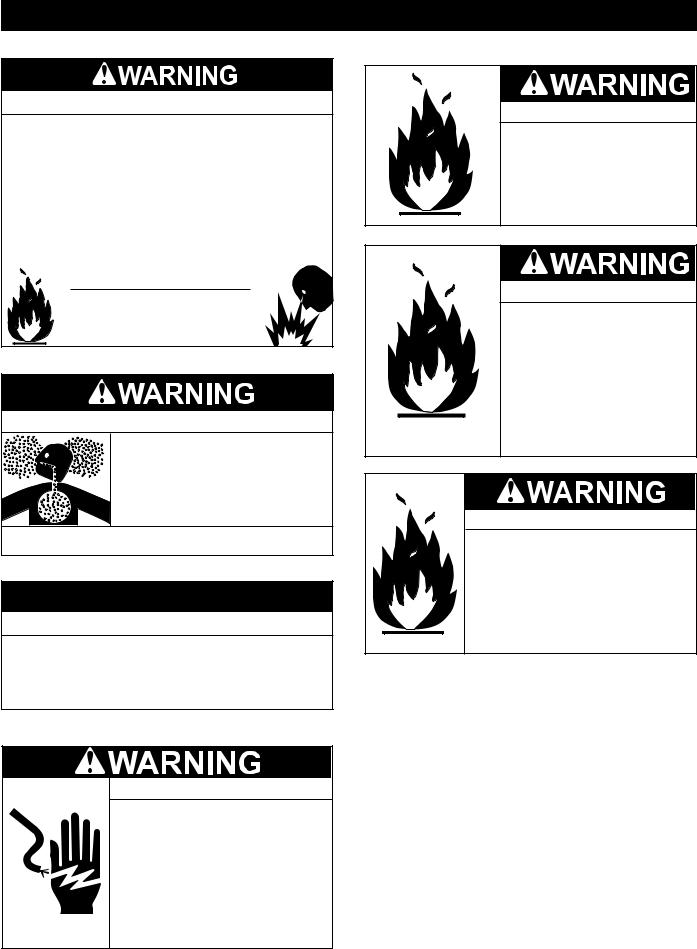
WARNING: If the information in these instructions is not followed exactly, a fire or explosion may result causing property damage, personal injury or death.
Do not store or use gasoline or other flammable vapors and liquids in the vicinity of this or any other appliance.
WHAT TO DO IF YOU SMELL GAS:
•Do not try to light any appliance.
•Do not touch any electrical switch; do not use any phone in your building.
•Immediately call your gas supplier from a neighbor’s phone. Follow the gas supplier’s instructions.
•If you cannot reach your gas supplier, call the fire department.
Installation and service must be performed by a qualified installer, service agency or the gas supplier.
POWER DIRECT VENT GAS MODELS WITH DIRECT SPARK IGNITION
MODELS
PG10/GHX/GSP/GTP Series 200, 201
NATURAL GAS & PROPANE
Thankyouforbuyingthisenergyefficientwaterheater. |
• For Your Safety • |
|
We appreciate your confidence in our products. |
AN ODORANT IS ADDED TO THE GAS USED |
|
BY THIS WATER HEATER. |
||
|
ALL TECHNICAL AND WARRANTY QUESTIONS: SHOULD BE DIRECTED TO THE LOCAL DEALER FROM WHOM THE WATER HEATER WAS
PURCHASED. IF YOU ARE UNSUCCESSFUL, CALL THE TECHNICAL SUPPORT PHONE NUMBER SHOWN ON THE WATER HEATER LABELING.
|
KEEP THIS MANUAL IN THE POCKET ON HEATER FOR FUTURE REFERENCE |
|
|
|
WHENEVER MAINTENANCE ADJUSTMENT OR SERVICE IS REQUIRED. |
|
|
PRINTED 0517 |
1 |
100286999_2000536191_Rev C |
|
|
|
|
|

TABLE OF CONTENTS
SAFE INSTALLATION, USE AND SERVICE................................. |
3 |
APPROVALS.................................................................................. |
3 |
GENERAL SAFETY INFORMATION............................................. |
4 |
Precautions............................................................................... |
4 |
Grounding Instructions.............................................................. |
4 |
INSTALLATION REQUIREMENTS FOR THE COMMONWEALTH |
|
OF MASSACHUSETTS................................................................. |
7 |
INTRODUCTION............................................................................ |
8 |
Abbreviations Used................................................................... |
8 |
Qualifications............................................................................ |
8 |
Preparing For The Installation................................................... |
8 |
MODEL CHARACTERISTICS....................................................... |
9 |
FEATURES AND COMPONENTS............................................... |
10 |
Controls And Switches............................................................ |
13 |
INSTALLATION CONSIDERATIONS........................................... |
14 |
Locating The Water Heater..................................................... |
14 |
Insulation Blankets.................................................................. |
15 |
Combustion Air And Ventilation............................................... |
15 |
Corrosion and Water Quality................................................... |
15 |
INSTALLATION REQUIREMENTS.............................................. |
16 |
Gas Supply Systems............................................................... |
16 |
Supply Gas Regulator............................................................. |
16 |
Power Supply.......................................................................... |
16 |
Mixing Valves.......................................................................... |
17 |
Circulation Pumps................................................................... |
17 |
Space Heating And Potable Water System............................. |
18 |
Storage Tank Installation......................................................... |
18 |
Solar Installation..................................................................... |
18 |
Closed Water Systems............................................................ |
18 |
Thermal Expansion................................................................. |
18 |
Temperature-Pressure Relief Valve........................................ |
19 |
Condensate DRAIN................................................................ |
20 |
VENTING INSTALLATION........................................................... |
21 |
Vent Installation Considerations.............................................. |
21 |
General Venting Instructions................................................... |
21 |
Approved Vent/Intake Material................................................ |
21 |
Polypropylene Installations..................................................... |
22 |
Vent Pipe Termination............................................................. |
22 |
Planning The Vent System...................................................... |
22 |
Integrated Filter Installation..................................................... |
23 |
Direct Vent Air Intake Moisture Protection.............................. |
24 |
Horizontal Vent Terminal Installation....................................... |
24 |
Vertical Vent Terminal Installation........................................... |
25 |
Termination Clearances Sidewall Direct Vent......................... |
26 |
Direct Vent Installation Diagrams............................................ |
27 |
Concentric Vent Installation.................................................... |
28 |
Venting Multiple Units............................................................. |
29 |
WATER HEATER INSTALLATION .............................................. |
30 |
CONDENSATE DRAIN INSTALLATION................................. |
30 |
Supply Gas Line Installation................................................... |
30 |
Gas Line Leak Testing............................................................. |
31 |
Purging.................................................................................... |
31 |
Electrical Wiring...................................................................... |
32 |
Water Line Connections.......................................................... |
32 |
TEMPERATURE REGULATION.................................................. |
34 |
HIGH TEMPERATURE LIMIT CONTROL (ECO)................... |
34 |
Thermostat Control................................................................. |
34 |
CONTROL SYSTEM OPERATION.............................................. |
35 |
Overview................................................................................. |
35 |
Control System Navigation..................................................... |
35 |
User Settings & Control System Menus.................................. |
38 |
START UP.................................................................................... |
43 |
Start Up Conditions................................................................. |
43 |
Prior To Start up...................................................................... |
43 |
Filling The Water Heater......................................................... |
43 |
Initial Start Up......................................................................... |
44 |
Lighting & Operation Labels.................................................... |
45 |
Checking The Firing Rate....................................................... |
46 |
Gas Input Rate........................................................................ |
46 |
High Altitude Installations........................................................ |
46 |
TROUBLESHOOTING................................................................. |
47 |
Installation Checklist............................................................... |
47 |
Sequence Of Operation.......................................................... |
47 |
Sequence Of Operation Flow Chart........................................ |
48 |
Operational Problems............................................................. |
49 |
Fault And Alert Conditions....................................................... |
50 |
LEAKAGE CHECKPOINTS......................................................... |
52 |
PERIODIC MAINTENANCE......................................................... |
53 |
Venting System Inspection...................................................... |
53 |
Integrated Filter Preventative Maintenance............................. |
53 |
Temperature-Pressure Relief Valve Test................................. |
53 |
Draining and Flushing............................................................. |
54 |
Service.................................................................................... |
54 |
DIAGRAMS.................................................................................. |
55 |
CCB - Central Control Board Layout....................................... |
55 |
Wiring Diagram....................................................................... |
56 |
Piping Diagrams...................................................................... |
58 |
NOTES......................................................................................... |
60 |
NOTES......................................................................................... |
61 |
2

SAFE INSTALLATION, USE AND SERVICE
The proper installation, use and servicing of this water heater is extremely important to your safety and the safety of others.
Many safety-related messages and instructions have been provided in this manual and on your own water heater to warn you and others of a potential injury hazard. Read and obey all safety messages and instructions throughout this manual. It is very important that the meaning of each safety message is understood by you and others who install, use, or service this water heater.
This is the safety alert symbol. It is used to alert you to potential personal injury hazards. Obey all safety messages that follow this symbol to avoid possible injury or death.
DANGER indicates an imminently
DANGER hazardous situation which, if not avoided, will result in injury or death.
WARNING indicates a potentially hazardous
WARNING situation which, if not avoided, could result in injury or death.
CAUTION indicates a potentially hazardous
CAUTION situation which, if not avoided, could result in minor or moderate injury.
CAUTION used without the safety alert CAUTION symbol indicates a potentially hazardous
situation which, if not avoided, could result in property damage.
All safety messages will generally tell you about the type of hazard, what can happen if you do not follow the safety message, and how to avoid the risk of injury.
APPROVALS
LOW LEAD
CONTENT
3

GENERAL SAFETY INFORMATION
PRECAUTIONS
DO NOT USE THIS WATER HEATER IF ANY PART HAS BEEN EXPOSED TO FLOODING OR WATER DAMAGE.
Immediately call a qualified service technician to inspect the water heater and to make a determination on what steps should be taken next.
If the unit is exposed to the following, do not operate heater until all corrective steps have been made by a qualified service technician.
1.External fire.
2.Damage.
3.Firing without water.
GROUNDING INSTRUCTIONS
This water heater must be grounded in accordance with the National Electrical Code and/or local codes. These must be followed in all cases. Failure to ground this water heater properly may also cause erratic control system operation.
This water heater must be connected to a grounded permanent wiring system; or an equipment grounding conductor must be run with the circuit conductors and connected to the equipment grounding terminal or lead on the water heater.
Verify the power to the water heater is turned off before performing any service procedures. The Enable/Disable switch at the base of the water heater disables the 24 volt gas control valve. Electrical supply must be turned off at circuit breaker serving water heater.
Read and understand this instruction manual and the safety messages herein before installing, operating or servicing this water heater.
Failure to follow these instructions and safety messages could result in death or serious injury.
This manual must remain with the water heater.
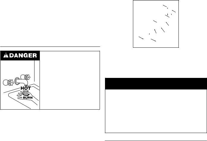
Water temperature over 125°F (52°C) can cause severe burns instantly resulting in severe injury or death.
Children, the elderly and the physically or mentally disabled are at highest risk for scald injury.
Feel water before bathing or showering.
Temperature limiting devices such as mixing valves must be installed when required by codes and to ensure safe temperatures at fixtures.
Explosion Hazard
 Overheated water can cause water tank explosion.
 Properly sized Temperature - Pressure Relief Valve must be installed in the opening provided.
CAUTION
Improper installation, use and service may result in property damage.
•Do not operate water heater if exposed to flooding or water damage.
•Install in location with drainage.
•Fill tank with water before operation.
•Properly sized thermal expansion tanks are required on all closed water systems.
Refer to this manual for installation and service.
4

GENERAL SAFETY INFORMATION
5
GENERAL SAFETY INFORMATION
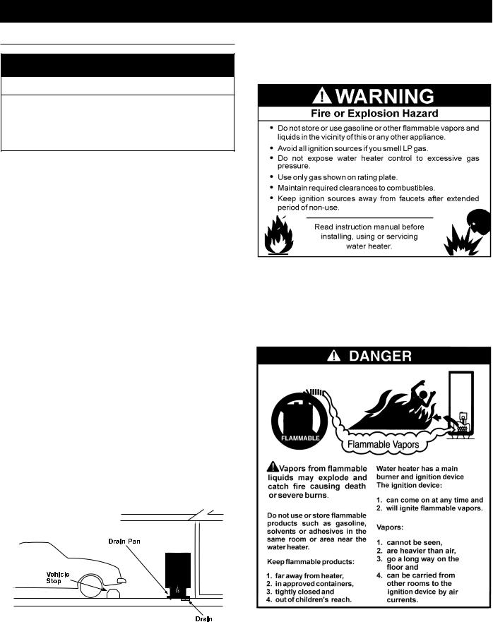
Fire or Explosion Hazard
 Do not store or use gasoline or other flammable vapors and liquids in the vicinity of this or any other appliance.
 Avoid all ignition sources if you smell gas.
 Do not expose gas control valve/ thermostat to excessive gas pressure.
 Use only the gas shown on the water heater rating plate.
 Maintain required clearances to combustibles.
 Keep ignition sources away from faucets after extended periods of non-use.
Read instruction manual before installing, using or servicing water heater.
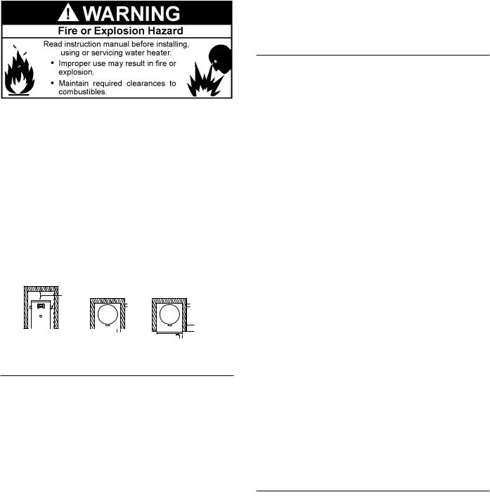
Breathing Hazard - Carbon Monoxide Gas
 Do not obstruct water heater air intake
with insulating blanket.
 Gas and carbon monoxide detectors
are available.
 Install water heater in accordance with
the instruction manual.
Breathing carbon monoxide can cause brain damage or death. Always read and understand instruction manual.
CAUTION
Property Damage Hazard
•All water heaters eventually leak.
•Do not install without adequate drainage.
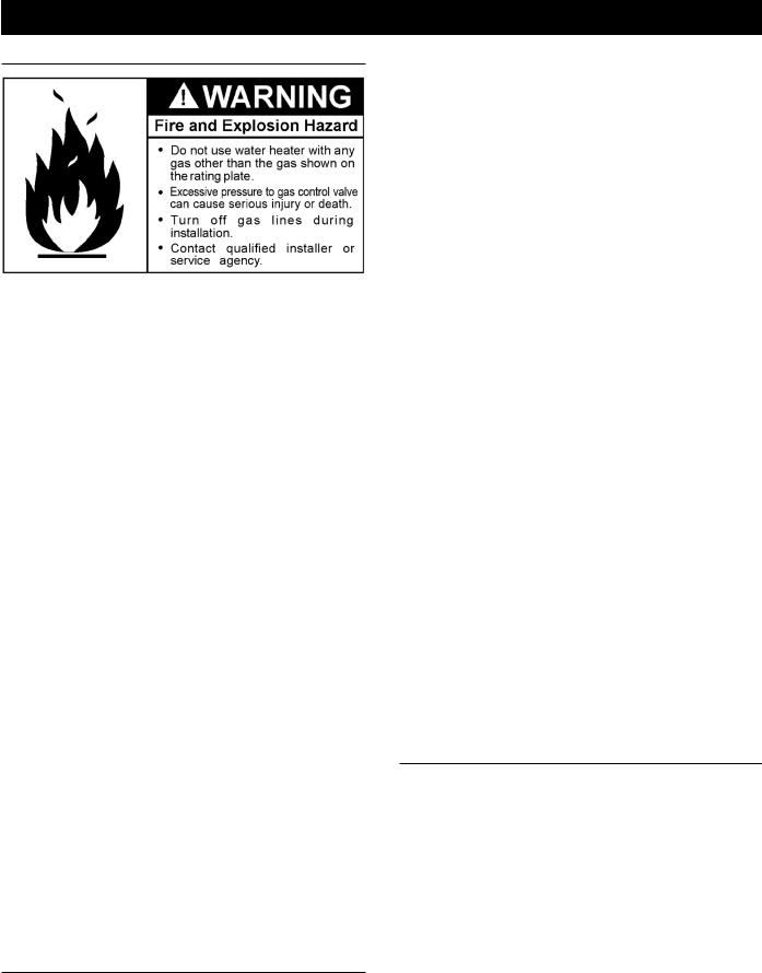
Electrical Shock Hazard
•Turn off power to the water heater before performing any service.
•Label all wires prior to disconnecting when performing service. Wiring errors can cause improper and dangerous operation.
•Verify proper operation after servicing.
•Failure to follow these instructions can result in personal injury or death.
Fire Hazard
For continued protection against risk of fire:
 Do not install water heater on carpeted floor.
 Do not operate water heater if exposed to flooding or water damage.
Fire and Explosion Hazard
 Use joint compound or Teflon tape compatible with propane gas.
 Leak test gas connections before placing the water heater in operation.
 Disconnect gas piping at main gas shutoff valve before leak testing.
 Install sediment trap in accordance with NFPA 54.
Fire and Explosion Hazard
 Do not use water heater with any gas other than the gas shown on the rating plate.
 Excessive gas pressure to gas control valve can cause serious injury or death.
 Turn off gas lines during installation.
 Contact a qualified installer or service technician for installation and service.
6

INSTALLATION REQUIREMENTS FOR THE COMMONWEALTH OF MASSACHUSETTS
For all side wall terminated, horizontally vented power vent, direct vent, and power direct vent gas fueled water heaters installed in every dwelling, building or structure used in whole or in part for residential purposes, including those owned or operated by the Commonwealth and where the side wall exhaust vent termination is less than seven (7) feet above finished grade in the area of the venting, including but not limited to decks and porches, the following requirements should be satisfied:
INSTALLATION OF CARBON MONOXIDE DETECTORS At the time of installation of the side wall horizontal vented gas fueled equipment, the installing plumber or gasfitter should observe that a hard wired carbon monoxide detector with an alarm and battery back-up is installed on the floor level where the gas equipment is to be installed. In addition, the installing plumber or gasfitter should observe that a battery operated or hard wired carbon monoxide detector with an alarm is installed on each additional level of the dwelling, building or structure served by the sidewall horizontal vented gas fueled equipment. It should be the responsibility of the property owner to secure the services of qualified licensed professionals for the installation of hard wired carbon monoxide detectors.
In the event that the side wall horizontally vented gas fueled equipment is installed in a crawl space or an attic, the hard wired carbon monoxide detector with alarm and battery back-up may be installed on the next adjacent floor level.
In the event that the requirements of this subdivision can not be met at the time of completion of installation, the owner should have a period of thirty (30) days to comply with the above requirements provided that during said thirty (30) day period, a battery operated carbon monoxide detector with an alarm should be installed.
APPROVED CARBON MONOXIDE DETECTORS Each carbon monoxide detector as required in accordance with the above provisions should comply with NFPA 720 and be ANSI/UL 2034 listed and CSA certified.
SIGNAGE A metal or plastic identification plate should be permanently mounted to the exterior of the building at a minimum height of eight (8) feet above grade directly in line with the exhaust vent terminal for the horizontally vented gas fueled heating appliance or equipment. The sign should read, in print size no less than one-half (1/2) inch in size, GAS VENT DIRECTLY
BELOW. KEEP CLEAR OF ALL OBSTRUCTIONS.
INSPECTION The state or local gas inspector of the side wall horizontally vented gas fueled equipment should not approve the installation unless, upon inspection, the inspector observes carbon monoxide detectors and signage installed in accordance with the provisions of 248 CMR 5.08(2)(a) 1 through 4.
EXEMPTIONS: The following equipment is exempt from 248 CMR 5.08(2)(a)1 through 4:
1.The equipment listed in Chapter 10 entitled Equipment Not Required To Be Vented in the most current edition of NFPA
54as adopted by the Board; and
2.Product Approved side wall horizontally vented gas fueled equipment installed in a room or structure separate from the dwelling, building, or structure used in whole or in part for residential purposes.
MANUFACTURER REQUIREMENTS - GAS EQUIPMENT VENTING SYSTEM PROVIDED When the manufacturer of Product Approved side wall horizontally vented gas equipment provides a venting system design or venting system components with the equipment, the instructions provided by the manufacturer for installation of the equipment and the venting system should include:
1.Detailed instructions for the installation of the venting system design or the venting system components; and
2.A complete parts list for the venting system design or venting system.
MANUFACTURER REQUIREMENTS - GAS EQUIPMENT VENTING SYSTEM NOT PROVIDED When the manufacturer of a Product Approved side wall horizontally vented gas fueled equipment does not provide the parts for venting the flue gases, but identifies special venting systems, the following requirements should be satisfied by the manufacturer:
1.The referenced special venting system instructions should be included with the appliance or equipment installation instructions; and
2.The special venting systems should be Product Approved by the Board, and the instructions for that system should include a parts list and detailed installation instructions.
Acopy of all installation instructions for all ProductApproved side wall horizontally vented gas fueled equipment, all venting instructions, all parts lists for venting instructions, and/or all venting design instructions should remain with the appliance or equipment at the completion of the installation.
7

INTRODUCTION
Thank You for purchasing this water heater. Properly installed and maintained, it should give you years of trouble free service.
ABBREVIATIONS USED
Abbreviations found in this Instruction Manual include :
•ANSI - American National Standards Institute
•ASME - American Society of Mechanical Engineers
•AHRI - Air-Conditioning, Heating and Refrigeration Institute
•NEC - National Electrical Code
•NFPA - National Fire Protection Association
•UL - Underwriters Laboratory
•CSA - Canadian Standards Association
QUALIFICATIONS
QUALIFIED INSTALLER OR SERVICE AGENCY
Installation and service of this water heater requires ability equivalent to that of a QualifiedAgency (as defined byANSI below) in the field involved. Installation skills such as plumbing, air supply, venting, gas supply and electrical supply are required in addition to electrical testing skills when performing service.
ANSI Z223.1 2006 Sec. 3.3.83: “Qualified Agency” - “Any individual, firm, corporation or company that either in person or through a representative is engaged in and is responsible for (a) the installation, testing or replacement of gas piping or (b) the connection, installation, testing, repair or servicing of appliances and equipment; that is experienced in such work; that is familiar with all precautions required; and that has complied with all the requirements of the authority having jurisdiction.”
If you are not qualified (as defined by ANSI above) and licensed or certified as required by the authority having jurisdiction to perform a given task do not attempt to perform any of the procedures described in this manual. If you do not understand the instructions given in this manual do not attempt to perform any procedures outlined in this manual.
PREPARING FOR THE INSTALLATION
1.Read the entire manual before attempting to install or operate the water heater. Pay close attention to the General Safety Information on Page 4 through Page 6. If you don’t follow the safety rules, the water heater may not operate safely. It could cause property damage, injury and/or death.
This manual contains instructions for the installation, operation, and maintenance of the water heater. It also contains warnings throughout the manual that you must read and be aware of. All warnings and all instructions are essential to the proper operation of the water heater and your safety. Detailed installation diagrams are also found in this manual. These diagrams will serve to provide the installer with a reference. It
is essential that all venting, water piping, gas piping and wiring be installed as shown.
Particular attention should be given to the installation of thermometers at the locations indicated in the piping diagrams as these are necessary for checking the operation of the water heater.
The principal components of the water heater are identified in FeaturesandComponentsbeginningonPage10inthismanual. Use this reference to locate and identify various components on the water heater.
See the Installation Checklist and Troubleshooting on page 47. By using this checklist the user may be able to make minor operational adjustments and avoid unnecessary service calls. However, service and diagnostic procedures should only be performed by a Qualified Service Agency.
NOTE: Costs to correct installation errors are not covered under the limited warranty.
2.Be sure to turn off power when working on or near the electrical system of the water heater. Never touch electrical components with wet hands or when standing in water.
3.The installation must conform to all instructions contained in this manual and the local code authority having jurisdiction. These shall be carefully followed in all cases.Authorities having jurisdiction should be consulted before installation begins if there are any questions regarding compliance with local, state or national codes.
In the absence of local codes, the installation must comply with the current editions of the National Fuel Gas Code, ANSI Z223.1/NFPA 54 and the National Electrical Code, NFPA 70. All documents are available from the Canadian Standards Association, 8501 East Pleasant Valley Road, Cleveland, OH 44131. NFPA documents are also available from the National Fire Protection Association, 1 Batterymarch Park, Quincy, MA
02269.
4.If after reading this manual you have any questions or do not understand any portion of the instructions, call the toll free number on the back cover of this manual for technical assistance. In order to expedite your request, please have the full Model, Serial and Series number of the water heater you are working with available for the technician. This information is located on the water heater’s rating plate.
5.Carefully plan the placement of the water heater. Examine the location to ensure that it complies with the requirements in Locating The Water Heater on Page 14.
8

MODEL CHARACTERISTICS
Table 1 – GAS AND ELECTRICAL CHARACTERISTICS
*Manifold Pressure |
Electrical Characteristics |
|||
Gas Type |
“WC |
kPA |
Volts/Hz |
Amperes |
|
|
|
|
|
Nat./LP |
0 |
0 |
120/60 |
<7 |
*The manifold pressure is the factory setting and is not adjustable. A negative pressure will be seen with just the blower running without the Gas Control Valve open.
All models - Maximum Supply Pressure: 14 inches W.C. (3.48kPa)
Minimum Supply Pressure for Natural Gas: 3.50” (.87kPa)
Minimum Supply Pressure for Propane Gas: 8.00” (1.99kPa)
Minimum pressure must be maintained under both load and no load (dynamic and static) conditions.
Table 2 – RECOVERY CAPACITIES
Input |
|
|
|
|
|
|
|
|
Recovery Capacities |
|
|
|
|
|
|||
|
|
|
|
|
|
|
|
|
|
|
|
|
|
|
|
|
|
Rating |
|
Rating |
Temp. |
|
F |
30 |
40 |
50 |
60 |
70 |
80 |
90 |
100 |
110 |
120 |
130 |
140 |
(Btu/hr) |
|
(kW) |
Rise |
|
C |
17 |
22 |
28 |
33 |
39 |
44 |
50 |
56 |
61 |
67 |
72 |
78 |
100,000 |
|
29.3 |
GPH |
|
381 |
286 |
229 |
190 |
163 |
143 |
127 |
114 |
104 |
95 |
88 |
82 |
|
|
LPH |
|
1442 |
1082 |
865 |
721 |
618 |
541 |
481 |
433 |
393 |
361 |
333 |
309 |
|||
|
|
|
|
||||||||||||||
130,000 |
|
38.1 |
GPH |
|
495 |
371 |
297 |
248 |
212 |
186 |
165 |
149 |
135 |
124 |
114 |
106 |
|
|
LPH |
|
1875 |
1406 |
1125 |
937 |
803 |
703 |
625 |
562 |
511 |
469 |
433 |
402 |
|||
|
|
|
|
||||||||||||||
150,000 |
|
44.0 |
GPH |
|
571 |
429 |
343 |
286 |
245 |
214 |
190 |
171 |
156 |
143 |
132 |
122 |
|
|
LPH |
|
2163 |
1622 |
1298 |
1082 |
927 |
811 |
721 |
649 |
590 |
541 |
499 |
464 |
|||
|
|
|
|
||||||||||||||
175,000 |
|
51.3 |
GPH |
|
667 |
500 |
400 |
333 |
286 |
250 |
222 |
200 |
182 |
167 |
154 |
143 |
|
|
LPH |
|
2524 |
1893 |
1514 |
1262 |
1082 |
946 |
841 |
757 |
688 |
631 |
582 |
541 |
|||
|
|
|
|
||||||||||||||
199,000 |
|
58.3 |
GPH |
|
758 |
569 |
455 |
379 |
325 |
284 |
253 |
227 |
207 |
190 |
175 |
162 |
|
|
LPH |
|
2870 |
2152 |
1722 |
1435 |
1230 |
1076 |
957 |
861 |
783 |
717 |
662 |
615 |
|||
|
|
|
|
||||||||||||||
Recovery capacity based on 95% thermal efficiency.
9

FEATURES AND COMPONENTS
34 GALLON NOMINAL CAPACITY UNIT
|
|
**11 |
|
|
|
**25 |
**12 |
|
5 |
|
|
|
|
|
|
|
|
6 |
7 |
|
|
31 |
|
|
|
|
|
|
4 |
|
|
17 |
|
|
**34 |
|
14 |
|
|
|
|
|
|
|
|
|
20 |
|
8 |
|
|
|
|
|
|
32 |
33 |
11 |
|
|
|
|
||
|
|
30 |
23 |
|
|
24 |
15 |
|
|
|
|
|
|
27
28
32
**33
15

16
26
29
13
*CAUTION HARNESS HAS 120 VAC. IN OPERATION.
**See Venting Installation and Condensate Piping for more information.


 1
1 

 2
2 


3
This is a view of the area at the bottom of
heater behind the Access Doors.
VACUUM RELIEF
VALVE
*INSTALL PER LOCAL CODES
Figure 1. 34 GALLON NOMINAL CAPACITY UNIT
10
FEATURES AND COMPONENTS (CONT.)
50 GALLON NOMINAL CAPACITY UNIT
**25
**34
32
24
27
|
**11 |
|
|
|
**12 |
|
5 |
|
|
|
|
|
|
6 |
7 |
31 |
|
|
|
|
|
|
4 |
17 |
|
|
|
14 |
|
|
|
20 |
|
|
|
|
|
|
8 |
|
33 |
11 |
|
9 |
30 |
23 |
|
|
15 |
|
|
10 |
|
|
|
|
|
|
1 |
|
2 |
|
|
21, 22 |
3 |
|
|
28
32
**33
15

16
26
29
13
*CAUTION HARNESS HAS 120 VAC. IN OPERATION.
**See Venting Installation and Condensate Piping for more information.
17 18


 19
19 
**11 **12
This is a view of the area at the bottom of
heater behind the Access Doors.
VACUUM RELIEF VALVE
*INSTALL PER LOCAL CODES
Figure 2. 50 GALLON NOMINAL CAPACITY UNIT
11

FEATURES AND COMPONENTS (CONT.)
1:Control Assembly
2:Blocked Intake Switch
3:Blocked Outlet Switch
4:Blower Assembly
5:Burner Assembly
6:Flame Sensor
7:Igniter Assembly
8:Gas Control Valve Assembly
9:Display Board
10:Display Enclosure
**11: Exhaust Elbow Assembly
**12: Condensate Drain Outlet
13:Enable / Disable Switch
14:Hot Water Outlet
15:Gas Supply
16:Main Manual Gas Shutoff Valve
17:Union
18:Inlet Water Shutoff Valve
19:Cold Water Inlet
20:T & P Relief Valve
21:Rating Plate
22:Labels
23:Drain Valve
24.Upper Temperature Probe (ECO)
**25: Exhaust Vent Terminal 26: Drain Pan
27: Insulation
28: Lower Temperature Probe 29: Access Door
30: Spark Module
31.Air Intake Pipe
32.Additional Side Taps
33.Intake Air Connection
**34. Intake Vent Terminal
12

CONTROLS AND SWITCHES
This model is provided with two pressure switches. These switches are essential to the safe and proper operation of the unit.All switches are wired in series. The controller is set up to shut the unit down whenever there is a failure of any of the switches. It is important to understand the purpose of each switch.
Blocked Outlet
Switch
Blocked Intake
Switch
34 GALLON NOMINAL CAPACITY UNIT
Blocked Outlet
Switch
Blocked Intake
Switch
50 GALLON NOMINAL CAPACITY UNIT
Figure 3
BLOCKED OUTLET SWITCH
The Blocked Outlet Switch is set up to shut the unit off when a buildup of positive pressure in the exhaust vent pipe occurs. This switch is a positive pressure switch that requires an increase in pressure to change the electrical contacts from normally closed to open. When this switch prevents the unit from igniting, most likely the exhaust is blocked by some means. Check to see if the condensate is allowed to flow freely from the exhaust elbow and for obstructions in the exhaust venting and exhaust vent terminal.Also verify that the vent length does not exceed the maximum allowed as shown in Planning the Vent System beginning on page 22.
BLOCKED INTAKE SWITCH
The Blocked Intake Switch is set up to shut the unit off when a buildup of negative pressure in the intake air pipe occurs. This switch is a negative pressure switch that requires an increase in negative pressure to change the electrical contacts from normally closed to open. The switch is connected to the pressure tap on the PVC pipe connected to the inlet of the blower. When this switch prevents the unit from igniting, most likely the intake is blocked. Verify that the integrated filter on the intake air connection, the intake air pipe, and the intake air termination are free of obstructions that may prevent air from entering the unit. Also Verify the intake air pipe length does not exceed the maximum allowed in Planning the Vent
System beginning on page 22.
WATER HEATING ENABLE/DISABLE SWITCH
IMPORTANT: The Enable/Disable switch listed in this manual is NOT an “on/off” switch and does not disconnect 120 volt power to the CCB and other heater components.
When in the “Disabled” position the switch removes electrical power from the gas control valve so that water heating is disabled. The display, CCB, and other electrical components will still be energized and the display will read “Water Heating Disabled”.
SPARK IGNITER
The Spark Igniter is a device that ignites the main burner by spark. When high voltage is applied to the igniter, spark is generated to ignite the main burner.
CONFIGURATION KEY
The configuration key is located inside the control box. It provides for the ability of the heater to retain information collected over its lifetime, even if the control board is replaced because of failure.
The configuration key should stay with the heater.
13
INSTALLATION CONSIDERATIONS
LOCATING THE WATER HEATER
CAUTION
Property Damage Hazard
•All water heaters eventually leak.
•Do not install without adequate drainage.
Carefullychoosealocationforthenewwaterheater.Theplacement is a very important consideration for the safety of the occupants in the building and for the most economical use of the water heater.
Whether replacing an existing water heater or installing the water heater in a new location observe the following critical points:
1.The water heater must be located indoors.
2.The water heater must not be located in an area where it will be subject to freezing temperatures.
3.Locate the water heater so it is protected and not subject to physical damage by a moving vehicle. In garage installation avoid damage to your water heater by installing a vehicle stop as shown in Figure 4. Check state and local codes for requirements prior to installation.
4.Locate the water heater on a level surface.
5.Locate the water heater near a floor drain. The water heater should be located in an area where leakage of the tank or connections will not result in damage to the area adjacent to the water heater or to lower floors of the structure. When such locations cannot be avoided, it is recommended that a metal drain pan, piped to adequate drain, be installed under the water heater. Drain pan should be fabricated with sides at least 1-3/4” deep with diameter at least 2” greater than diameter of heater. Pan must not restrict combustion air flow.
6.Locate the water heater close to the point of major hot water usage.
7.Locate the water heater close to a 120 VAC power supply. See Power Supply on Page 16 for requirements.
8.Locate the water heater where an adequate supply of fresh air for combustion and ventilation can be obtained. See Combustion Air and Ventilation on Page 15.
9.Locate the water heater where the vent and intake air piping, when installed, will remain within the maximum equivalent lengths allowed. See Planning the Vent System on page 22.
11.Do not locate the water heater where the subsequent installation of the vent (exhaust) or intake air terminations would be objectionable due to noise at the termination(s). This includes locations close to or across from windows and doors. See Venting Installation beginning on page 21.
Do not locate water heater areas where flammable liquids (vapors) are likely to be present or stored (garages, storage and utility areas, etc.): Flammable liquids (such as gasoline, solvents, propane (LP or butane, etc.) and other substances (such as adhesives, etc.) emit flammable vapors which can be ignited by a gas water heater’s ignition device or main burner. The resulting flashback and fire can cause death or serious burns to anyone in the area.
Figure 4. GARAGE INSTALLATION
10.Do not locate the water heater where noise (such as the Combustion Blower) during normal operation will be objectionable in adjacent areas.
When the water heater is installed directly on carpeting, the water heater shall be installed on a metal or wood panel extending beyond the full width and depth of the water heater by at least 3″ (7.62 cm) in any direction or, if the water heater is installed in an alcove or closet, the entire floor shall be covered by the panel. The panel must be strong enough to carry the weight of the heater when full of water.
14
Minimumclearancesfromcombustiblematerialsarestatedonthedata plate located on the front of the water heater. Standard clearances are 0” (0 cm) at the sides and rear, 0” (0 cm) from the front, and 0” (0 cm) from the top. If the clearances from combustible material stated on the water heater differ from the standard clearances, install the water heater according to the clearances stated on the water heater.
Adequate clearance for inspection and service should be considered beforeinstallation. Aminimumof24”(61cm)offrontclearanceand4” (10.2 cm) on each side should be provided for access to replaceable and/orserviceablepartssuchasthermostats,drainvalve,condensate drain, temperature-pressure relief valve, and the vent connection (exhaust elbow).
Figure 5 may be used as a reference guide to locate the specific clearance locations. When installing the water heater, consideration must be given to proper location. The location selected should be as close to the wall as practicable and as centralized with the water piping system as possible.
|
CEILING |
TOP VIEW |
|
TOP VIEW |
|
|
0" MIN. |
OF CLOSET |
|
OF CLOSET |
|
|
WITHOUT DOOR |
WITHOUT DOOR |
|||
LEFT |
RIGHT |
0" MIN. |
0" MIN. |
||
WALL |
WALL |
||||
WATER |
|
WATER |
|||
|
|
HEATER |
|
HEATER |
|
|
FRONT VIEW |
*4" MIN. |
|
*24" MIN.(61cm) |
|
|
|
0" MIN. |
|||
*For service access |
|
|
|||
|
|
|
|||
Figure 5: MINIMUM CLEARANCE LOCATIONS
INSULATION BLANKETS
Insulation blankets are available to the general public for external use on gas water heaters but are not necessary with these products. The purpose of an insulation blanket is to reduce the standby heat loss encountered with storage tank heaters. Your water heater meets or exceeds the Energy PolicyAct standards with respect to insulation and standby loss requirements, making an insulation blanket unnecessary.
Should you choose to apply an insulation blanket to this heater, you should follow these instructions (For identification of components mentioned below. See Figures 1, 2, and 3. Failure to follow these instructions can restrict the air flow required for proper combustion, potentiallyresultinginfire,asphyxiation,seriouspersonalinjuryordeath.
•Do not cover the control system LCD on top of the water heater.
•Do not cover theouterdoor,thermostat ortemperature-pressure relief valve.
•Do not cover the instruction manual. Keep it on the side of the water heater or nearby for future reference.
•Do obtainnewwarningandinstructionlabelsfromthemanufacturer for placement on the blanket directly over the existing labels.
•Do inspect the insulation blanket frequently to make certain it does not sag, thereby obstructing combustion air flow.
COMBUSTION AIR AND VENTILATION
A gas water heater cannot operate properly without the correct amount of air for combustion. Never obstruct the flow of ventilation air. If you have any doubts or questions at all, call your gas supplier. Failure to provide the proper amount of combustion air can result in a fire or explosion and cause death, serious bodily injury, or property damage.
Figure 6: COMBUSTION AIR AND VENTILATION
It is imperative that the water heater(s) be installed direct vent so that all air for combustion and ventilation is taken from outdoors.
Propellants of aerosol sprays and volatile compounds, (cleaners, chlorine based chemicals, refrigerants, etc.) in addition to being highly flammable in many cases, will also react to form corrosive acids when exposed to the combustion products of the water heater. The results can be hazardous, and also cause product failure. Air for combustion and ventilation must not come from a corrosive atmosphere.Any failure due to corrosive elements in the atmosphere is excluded from warranty coverage.
CORROSION AND WATER QUALITY
Water quality will vary from location to location and may contain contaminatesthatmayreducethelifeorperformanceofthewaterheater.
Contaminates which can reduce the life or performance of the water heater if present in high quantities include those which contribute to hardness(dissolvedmineralssuchassodium,calciumandmagnesium); plus chlorides and sulfates.Additionally, water that is too acidic or basic (measuredaspH)canreducethelifeofthewaterheater.Watertreatment systems (such as water softeners for hardness) should be used and maintained properly if the contaminate levels exceed the following:
Warranty is void in applications which exceed the water quality requirements listed below.
Total Hardness: |
12 grains per gal. (205 mg/liter) max. |
Chloride: |
200 mg/liter max. |
pH: |
6.5-8.0 |
Alkalinity: |
200 mg/liter max. |
15
INSTALLATION REQUIREMENTS
GAS SUPPLY SYSTEMS
Low pressure building gas supply systems are defined as those systems that cannot under any circumstances exceed 14” W.C. (1/2 PSI Gauge). These systems do not require pressure regulation. Measurements should be taken to insure that gas pressures are stable and fall within the requirements stated on the water heater rating plate. Readings should be taken with all gas burning equipment off (static pressure) and with all gas burning equipment running at maximum rate (dynamic pressure). The gas supply pressure must be stable within 1.5” W.C. from static to dynamic pressure to provide good performance. Pressure drops that exceed 1.5” W.C. may cause rough starting, noisy combustion or nuisance outages. Increases or spikes in static pressure during off cycles may cause failure to ignite or in severe cases damage to water heater gas control valves. If your low pressure system does NOT meet these requirements, the installer is responsible for the corrections.
High pressure building supply systems use pressures that exceed 14” W.C. (1/2 PSI Gauge). These systems must use field supplied regulators to lower the gas pressure to less than 14” W.C. (1/2
PSI Gauge). Water heaters require gas regulators that are properly sized for the water heater input and deliver the rating plate specified pressures. Gas supply systems where pressure exceeds 5 PSI often require multiple regulators to achieve desired pressures. Systems in excess of 5 PSI building pressure should be designed by gas delivery professionals for best performance. Water heaters connected to gas supply systems that exceed 14” W.C. (1/2 PSI Gauge) at any time must be equipped with a gas supply regulator.
All models require a minimum gas supply pressure of 3.5” W.C.(0.87 kPa) for natural gas and 8.0” W.C. (1.99 kPa) for propane. The minimum supply pressure is measured while gas is not flowing (static pressure) AND while gas is flowing (dynamic pressure). The supply pressure (static and dynamic) should never fall below 3.5” W.C.(0.87 kPa) for natural gas or 8.0” W.C. (1.99 kPa) for propane. The supply pressure should be measured with all gas fired water heaters connected to the common main firing at full capacity. If the supply pressure drops more than 1.5” W.C. (0.37 kPa) as gas begins to flow to the water heater then the supply gas system including the gas line and/or the gas regulator may be restricted or undersized. See Supply Gas Regulator on page 16 and Supply Gas Line Installation on page 30. The gas control valve on all models has a maximum gas supply pressure limit of 14” W.C.(3.48 kPa) The maximum supply pressure is measured while gas is not flowing (static pressure) AND while gas is flowing (dynamic pressure).
SUPPLY GAS REGULATOR
The maximum allowable gas supply pressure for this water heater is 14 inches W.C. (3.5 kPa). Install a positive lock-up gas pressure regulator in the gas supply line if inlet gas pressure can exceed 14 inches W.C. (3.5 kPa) at any time. Regulators must be sized/used according to manufacturer’s specifications.
If a positive lock-up regulator is required follow these instructions:
1.Positive lock-up gas pressure regulators must be rated at or above the input Btu/hr rating of the water heater they supply.
2.Supply gas regulators shall have inlet and outlet connections not less than the minimum supply gas line size for the water heater they supply
3.Positive lock-up gas pressure regulator(s) should be installed no closer than 3 feet (1 meter) and no farther than 8 feet (2.4 meters) from the water heater’s inlet gas connection.
4.After installing the positive lock-up gas pressure regulator(s) an initial nominal supply pressure setting of 7.0” W.C.(1.74 kPa) for Natural Gas and 11.0” W.C. (2.74 kPa) for Propane (LP) while the water heater is operating is recommended and will generally providegoodwaterheateroperation.Someadditionaladjustment may be required later to maintain a steady gas supply pressure.
5.When installing multiple water heaters in the same gas supply system it is recommended that individual positive lock-up gas pressure regulators be installed at each unit.
All gas piping must comply with local codes and ordinances or with current editions of the National Fuel Gas Code (ANSI Z223.1/ NFPA-54). Copper or brass tubing and fittings (except tin lined copper tubing) shall not be used.
If the gas control valve is subjected to pressures exceeding 1/2 psi (3.5 kPa), the damage to the gas control valve could result in a fire or explosion from leaking gas.
If the main gas line Shut-off serving all gas water heaters is used, also turn off the gas at each water heater. Leave all gas appliances shut off until the water heater installation is complete.
A gas line of sufficient size must be run to the water heater. Consult the current edition of the National Fuel Gas Code (ANSI Z223.1/ NFPA 54) and your gas supplier concerning pipe size.
There must be:
•A readily accessible manual shut off valve in the gas supply line serving the water heater, and
•A sediment trap ahead of the gas control valve to help prevent dirt and foreign materials from entering the gas control valve.
•A ground joint union of proper size between the manual shut off valve and gas control valve to permit servicing of the unit.
Be sure to check all the gas piping for leaks before lighting the water heater. Use a soapy water solution, not a match or open flame. Rinse off soapy solution and wipe dry.
POWER SUPPLY
The water heaters covered in this manual require a 120 VAC, 1Ø (single phase), 60Hz, 7 amp power supply and must also be electrically grounded in accordance with local codes or, in the absence of local codes, with the National Electrical Code, ANSI/
NFPA 70.
If any of the original wire as supplied with the water heater must be replaced, it must be replaced with 105°C rated wiring or its equivalent, except in the burner housing. In this case 200°C rated wire must be used.
DEDICATED POWER WIRING AND BREAKERS
Dedicated power supply wires, ground wiring and dedicated circuit breakers often prevent electrical line noise and should be considered when installing the water heater.
POWER FLUCTUATIONS AND ELECTRICAL NOISE
The water heater’s control system requires a source of stable clean electricity for proper operation. Connecting the water heater to a branch circuit that is subject to fluctuations in voltage level
16
or electrical line noise such as EMI (electro magnetic interference) or RFI (radio frequency interference) may cause erratic control system operation and malfunction.
A high quality power supply filter/suppressor must be installed if the above conditions exist. Call the technical support phone number for more information.
NOTE: Malfunctions caused by the power supply and the costs to install the power supply filters are not covered under the limited warranty.
MIXING VALVES
Water temperature over 125°F (52°C) can cause severe burns instantly resulting in severe injury or death.
Children, the elderly and the physically or mentally disabled are at highest risk for scald injury.
Feel water before bathing or showering.
Temperature limiting devices such as mixing valves must be installed when required by codes and to ensure safe temperatures at fixtures.
Water heated to a temperature which will satisfy clothes washing, dish washing, and other sanitizing needs can scald and cause permanent injury upon contact. Short repeated heating cycles caused by small hot water uses can cause temperatures at the point of use to exceed the water heater’s temperature setting by up to 20°F (11°C).
Some people are more likely to be permanently injured by hot water than others. These include the elderly, children, the infirm and the physically/mentally disabled. Table 3 shows the approximate time- to-burn relationship for normal adult skin. If anyone using hot water provided by the water heater being installed fits into one of these groups or if there is a local code or state law requiring a certain water temperatureatthepointofuse,thenspecialprecautionsmustbetaken.
In addition to using the lowest possible temperature setting that satisfies the demand of the application a Mixing Valve should be installed at the water heater or at the hot water taps to further reduce system water temperature. See Figure 7 below and Figures
51 through 53 in Piping Diagrams beginning on Page 58.
|
|
HOT WATER |
|||
|
|
OUTLET |
|
|
|
|
|
|
|
||
|
|
|
|
|
|
|
|
|
12” TO 15” |
||
TEMPERED WATER |
(30-38 cm) |
|
|||
|
|
|
|||
|
OUTLET |
|
|
|
|
COLD |
|
|
CHECK |
||
WATER |
|
|
VALVE |
||
INLET |
|
|
MIXING |
||
|
|
CHECK |
|||
|
|
VALVE |
|||
|
|
VALVE |
|||
|
|
|
|
|
|
|
|
TO TANK |
|||
|
|
INLET |
|||
Figure 7
Mixing valves are available at plumbing supply stores. Consult a
Qualified Installer or Service Agency. Follow mixing valve manufacturer’s instructions for installation of the valves.
In all cases, the following burn table must be used.
Table 3
Water Temperature |
Time for 1st Degree Burn |
Time for Permanent |
Burns |
||
°F (°C) |
(Less Severe Burns) |
2nd & 3rd Degree |
|
|
(Most Severe Burns) |
110 (43.3) |
(normal shower temp.) |
|
116 (46.7) |
(pain threshold) |
|
116 (46.7) |
35 minutes |
45 minutes |
122 (50) |
1 minute |
5 minutes |
131 (55) |
5 seconds |
25 seconds |
140 (60) |
2 seconds |
5 seconds |
149 (65) |
1 second |
2 seconds |
154 (67.8) |
instantaneous |
1 second |
(U.S. Government Memorandum, C.P.S.C., Peter L. Armstrong, Sept. 15, 1978)
CIRCULATION PUMPS
A circulating pump is used when a system requires a circulating loop or there is a storage tank used in conjunction with the water heater. The tank is provided with a 1” NPT recirculation loop return connection. See the Piping Diagrams section beginning on Page 58 for the installation location of circulating pumps.
See Circulation Pump Wiring Diagrams on page 57 for electrical hookup information. Install in accordance with the current edition of the National Electrical Code, NFPA 70.
Refer to the circulating pump manufacturer’s instructions for its operation, lubrication and maintenance instructions.
17

SPACE HEATING AND POTABLE WATER SYSTEM
Your water heater is equipped with additional side taps for use in space heating applications. See Features and Components on Page 10 for locations. If this water heater is to be used to supply both space heating and potable (drinking) water, the instructions listed below must be followed:
•Be sure to follow the manual(s) shipped with the air handler or other type heating system.
•This water heater cannot be used in space heating applications only.
•This water heater is not to be used as a replacement for an existing boiler installation.
•Do not use with piping that has been treated with chromates, boiler seal or other chemicals and do not add any chemicals to the water heater piping
•If the space heating system requires water temperatures in excess of 120°F, a mixing valve must be installed per the manufacturer’s instructions in the potable hot water supply to limit the risk of scald injury. See Mixing Valves on Page 17.
•Pumps, valves, piping and fittings must be compatible with potable water.
•A properly installed flow control valve is required to prevent thermosiphoning. Thermosiphoning is the result of a continuous flow of water through the air handler circuit during the off cycle. Weeping (blow off) of the temperature-pressure relief valve (T & P relief valve) or higher than normal water temperatures are the first signs of thermosiphoning.
•The hot water line from the water heater should be vertical past any mixing valve or supply line to the heating system to remove air bubbles from the system. Do not connect the water heater to any system or components previously used with non-potable water heating appliances when used to supply potable water.
STORAGE TANK INSTALLATION
When installing the water heater with a storage tank, see Figure
52 on page 59 in Piping Diagrams for suggestions.
NOTE: If tank temperature is set above 120°F and water is supplied for domestic use (hand washing, showering, etc.) a mixing valve should be installed in the hot water line to domestic fixtures. Installation must conform to local code requirements. If a check valve is installed in the cold water supply line, an expansion tank must be installed between the check valve and the water heater’s cold water inlet. Set storage tank temperature five degrees lower than the water heater’s temperature setting. Using the plug valve, adjust the flow in the recirculating line to five gallons per minute.
SOLAR INSTALLATION
If this water heater is used as a solar storage heater or as a backup for the solar system, the water supply temperatures to the water heater tank may be in excess of 120°F (48.9°C). A mixing valve must be installed in the water supply line to limit the supply temperature to 120°F (48.9°C).
NOTE: Solar water heating systems can often supply water with temperatures exceeding 180°F (82.2°C) and may result in water heater malfunction.
CLOSED WATER SYSTEMS
Water supply systems may, because of code requirements or such conditions as high line pressure, among others, have installed
devices such as pressure reducing valves, check valves, and back flow preventers. Devices such as these cause the water system to be a closed system.
THERMAL EXPANSION
As water is heated, it expands (thermal expansion). In a closed system the volume of water will grow when it is heated. As the volume of water grows there will be a corresponding increase in water pressure due to thermal expansion. Thermal expansion can cause premature tank failure (leakage). This type of failure is not covered under the limited warranty. Thermal expansion can also cause intermittent temperature-pressure relief valve operation: water discharged from the valve due to excessive pressure build up. This condition is not covered under the limited warranty. The temperature-pressure relief valve is not intended for the constant relief of thermal expansion.
A properly sized thermal expansion tank should be installed on all closed systems to control the harmful effects of thermal expansion. Contact a local plumbing service agency to have a thermal expansion tank installed.
NOTE: To protect against untimely corrosion of hot and cold water fittings, it is strongly recommended that di-electric unions or couplings be installed on this water heater (see Figure 8) when connected to copper pipe.
Hot |
|
|
Water |
Sweat |
|
Outlet |
||
Fittings |
||
|
||
|
Union |
Temperature-
Pressure
Relief Valve
Sweat
Fittings
Union
Cold


 Water
Water
Inlet
Shutoff
Valve
Figure 8
Figure 8 also shows the typical attachment of the water piping to the water heater. The water heater is equipped with 1” NPT
18
Loading...