


DEL-30
Table of contents
 Loading...
A.O. Smith DEL-30, DEL-40, DEL-50, DEN-30, DEN-40 Installation Manual
...
1
Instruction Manual
PRINTED 0515 322055-004
PLACE THESE INSTRUCTIONS ADJACENT TO HEATER AND NOTIFY OWNER TO KEEP FOR FUTURE REFERENCE.
COMMERCIAL ELECTRIC WATER HEATERS
Thank you for buying this energy efcient water heater.
We appreciate your condence in our products.
MODELS DEL-6/10/15/20 Series 102
DEL-30/40/50 Series 110
& DEN-30/40/52/66/80/120 Series 110
INSTALLATION - OPERATION - SERVICE
- MAINTENANCE - LIMITED WARRANTY
500 Tennessee Waltz Parkway
Ashland City, TN 37015
2
SAFE INSTALLATION, USE, AND SERVICE
The proper installation, use and servicing of this water heater is extremely important to your safety and the safety of others.
Many safety-related messages and instructions have been provided in this manual and on your own water heater to warn you and
others of a potential injury hazard. Read and obey all safety messages and instructions throughout this manual. It is very important
that the meaning of each safety message is understood by you and others who install, use, or service this water heater.
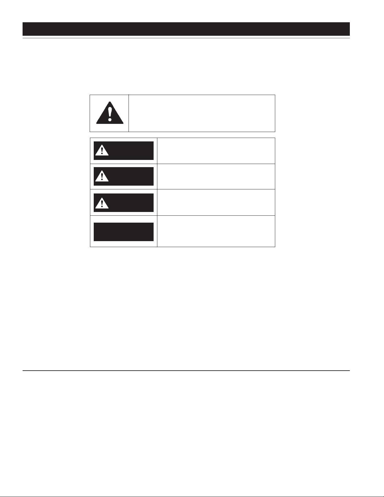
This is the safety alert symbol. It is used to alert you
to potential personal injury hazards. Obey all safety
messages that follow this symbol to avoid possible
injury or death.
IMPORTANT DEFINITIONS
• QualiedInstallerorServiceAgency:
Installation and service of this water heater requires ability equivalent to that of a Qualied Agency (as dened by ANSI below) in the
eld involved. Installation skills such as plumbing, electrical supply are required in addition to electrical testing skills when performing
service.
• ANSIZ223.12006Sec.3.3.83:
“Qualied Agency” - “Any individual, rm, corporation or company that either in person or through a representative is engaged in and is
responsible for (a) the installation, testing or replacement of gas piping or (b) the connection, installation, testing, repair or servicing of
appliances and equipment; that is experienced in such work; that is familiar with all precautions required; and that has complied with all
the requirements of the authority having jurisdiction.”
DANGER
WARNING
CAUTION
DANGER indicates an imminently hazardous
situation which, if not avoided, will result in
death or injury.
WARNING indicates a potentially hazardous
situation which, if not avoided, could result
in death or injury.
CAUTION indicates a potentially hazardous
situation which, if not avoided, could result
in minor or moderate injury.
CAUTION used without the safety alert
symbol indicates a potentially hazardous
situation which, if not avoided, could result
in property damage.
CAUTION
All safety messages will generally tell you about the type of hazard, what can happen if you do not follow the safety message, and
how to avoid the risk of injury.
The California Safe Drinking Water and Toxic Enforcement Act requires the Governor of California to publish a list of substances
known to the State of California to cause cancer, birth defects, or other reproductive harm, and requires businesses to warn of
potential exposure to such substances.
This product contains a chemical known to the State of California to cause cancer, birth defects, or other reproductive harm. This
appliance can cause low level exposure to some of the substances listed in the Act.
3
GENERAL SAFETY INFORMATION
When servicing this unit, verify the power to the unit is turned off prior to opening the control cabinet door.
PRECAUTIONS
DO NOT USE THIS WATER HEATER IF ANY PART HAS BEEN
EXPOSED TO FLOODING OR WATER DAMAGE. Immediately
call a qualied service technician to inspect the water heater and to
replace any part of the control system which has been under water.
If the unit is exposed to the following, do not operate heater until all
corrective steps have been made by a qualied service technician.
1. External re.
2. Damage.
3. Firing without water.
GROUNDING INSTRUCTIONS
This water heater must be grounded in accordance with the
National Electrical Code and/or local codes. These must be
followed in all cases. Failure to ground this water heater properly
may also cause erratic control system operation on ELECTRONIC
CONTROL models.
This water heater must be connected to a grounded metal, permanent
wiring system; or an equipment grounding conductor must be run with
the circuit conductors and connected to the equipment grounding
terminal or lead on the water heater.
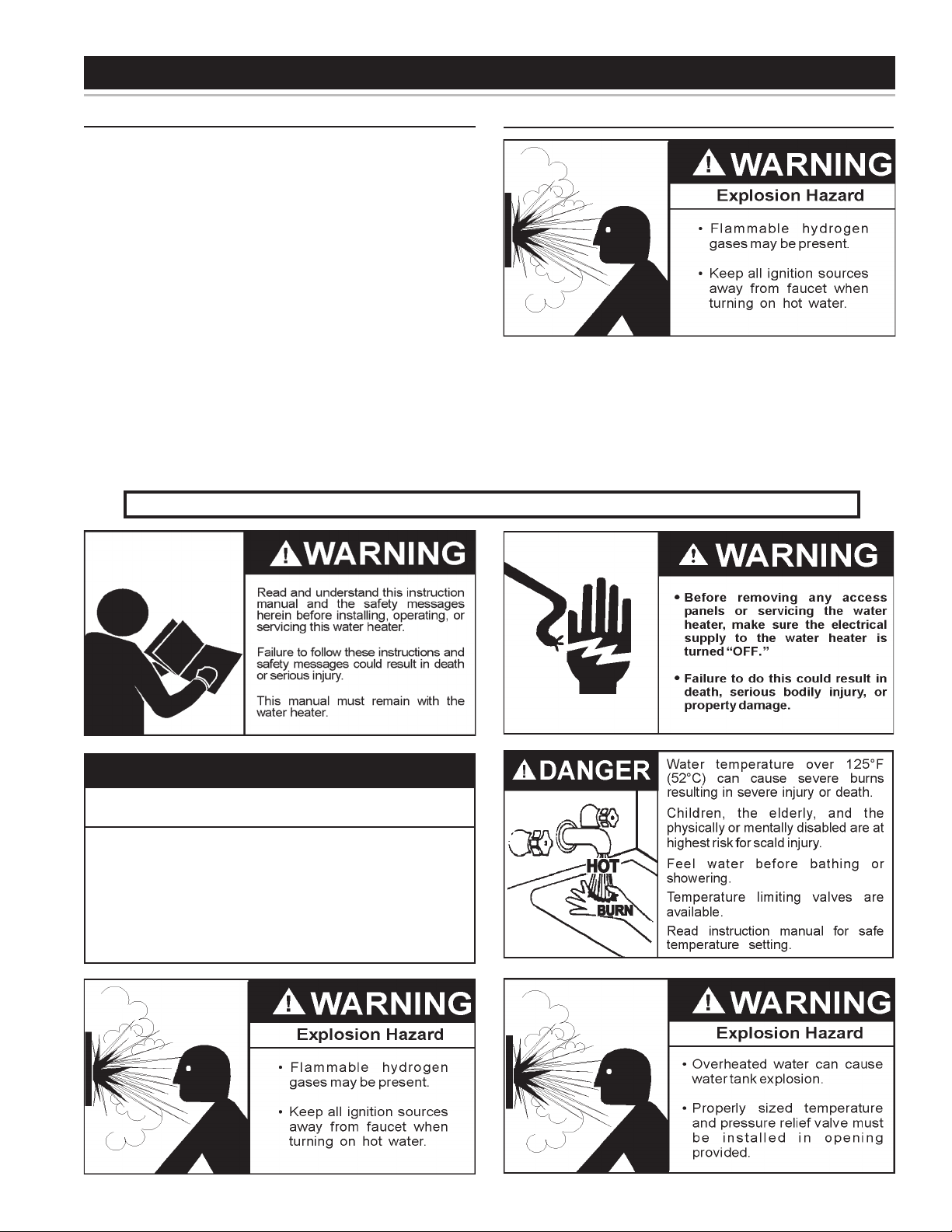
HYDROGEN GAS (FLAMMABLE)
Hydrogen gas can be produced in a hot water system served by this
heater that has not been used for a long period of time (generally two
weeks or more). Hydrogen gas is extremely ammable.
To reduce the
risk of injury under these conditions, it is recommended that the hot water
faucet be opened for several minutes at the kitchen sink before using any
electrical appliance connected to the hot water system. If hydrogen is present
there will probably be an unusual sound such as air escaping through the
pipe as the water begins to ow.
THERE SHOULD BE NO SMOKING
OR OPEN FLAME NEAR THE FAUCET AT THE TIME IT IS OPEN.
Improper installation, use and service may
result in property damage.
CAUTION
•
Do not operate water heater if any part has been
exposed to flooding or water damage.
•
Inspect anode rods regularly, replace when significantly depleted.
•
Install in location with drainage.
•
Fill tank with water before operation.
•
Properly sized thermal expansion tanks are required on all
closed water systems.
Refer to this manual for installation and service.
4
Thank You for purchasing this water heater. Properly installed
and maintained, it should give you years of trouble free service.
Abbreviations Found In This Instruction Manual:
• ANSI - American National Standards Institute
• AHRI - Air-Conditioning, Heating and Refrigeration Institute
• NEC - National Electrical Code
• NFPA - National Fire Protection Association
• UL - Underwriters Laboratory
PREPARING FOR THE INSTALLATION
1. Read the “General Safety Information” section of this manual
rst and then the entire manual carefully. If you don’t follow
the safety rules, the water heater may not operate safely. It
could cause DEATH, SERIOUS BODILY INJURY AND/OR
PROPERTY DAMAGE.
This manual contains instructions for the installation, operation,
and maintenance of the electric water heater. It also contains
warnings throughout the manual that you must read and be
aware of. All warnings and all instructions are essential to the
proper operation of the water heater and your safety. READ
THE ENTIRE MANUAL BEFORE ATTEMPTING TO INSTALL
OR OPERATE THE WATER HEATER.
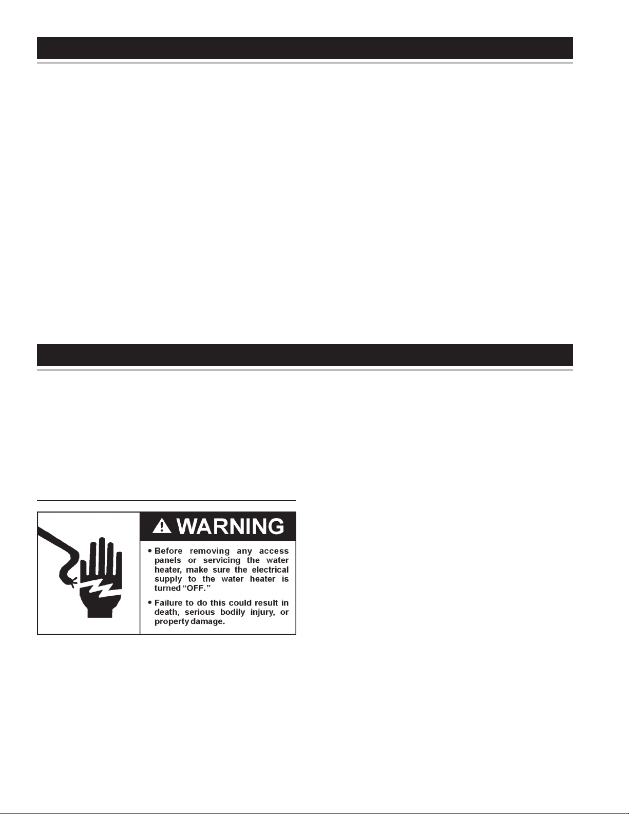
Be sure to turn off power when working on or near the
electrical system of the heater. Never touch electrical
components with wet hands or when standing in water.
When replacing fuses always use the correct size for the
circuit. see page 12.
The model and rating plates on page 6 interprets certain
markings into useful information. Both of these references should
be used to identify the heater, its components and optional
equipment.
2. The installation must conform with these instructions and the
local code authority having jurisdiction and the requirements
of the power company. In the absence of local codes, the
installation must comply with the latest editions of the National
Electrical Code, NFPA 70 or the Canadian Electrical Code CSA
C22.1. The National Electrical Code may be ordered from:
National Fire Protection Association, 1 Batterymarch Park,
Quincy, MA 02269. The Canadian Electrical Code is available
from the Canadian Standards Association, 8501 East Pleasant
Valley Road, Cleveland, OH 44131.
3. If after reading this manual you have any questions or do not
understand any portion of the instructions, call the toll free
number listed on the back cover of this manual for technical
assistance.
A sample rating plate is shown on page 6 of this manual. In
order to expedite your request, please have full model and serial
number available for the technician.
4. Carefully plan your intended placement of the water heater.
Examine the location to ensure the water heater complies with
the “Locating the New Water Heater” section in this manual.
Installation and service of this water heater requires ability
equivalent to that of a licensed tradesman or qualied agency
(page 2) in the eld involved. Plumbing and electrical work
are required.
TABLE OF CONTENTS
INTRODUCTION
SAFE INSTALLATION, USE, AND SERVICE....................................... 2
GENERAL SAFETY INFORMATION .................................................... 3
Precautions .................................................................................. 3
Hydrogen Gas (Flammable) ......................................................... 3
INTRODUCTION .................................................................................. 4
Preparing for the Installation ........................................................ 4
DIMENSIONS AND CAPACITIES DATA .............................................. 5
APPROVALS ........................................................................................ 6
MODEL AND RATING .......................................................................... 6
FEATURES AND COMPONENTS ....................................................... 7
Electronic Control Models ............................................................ 7
LOCATING THE NEW WATER HEATER ............................................. 8
Facts to Consider About the Location .......................................... 8
Clearances ................................................................................... 8
INSTALLATION .................................................................................... 9
Required Ability ............................................................................ 9
General ......................................................................................... 9
Contaminated Water ..................................................................... 9
Circulating Pump .......................................................................... 9
Insulation Blankets ....................................................................... 9
Temperature-Pressure Relief Valve .............................................. 9
Closed Water Systems ............................................................... 10
Thermal Expansion .................................................................... 10
ELECTRICAL ......................................................................................11
General ........................................................................................11
Branch Circuit ..............................................................................11
Calculating Amperage/Overcurrent Protection ............................11
WIRING DIAGRAMS .......................................................................... 12
OPERATION ....................................................................................... 13
General ....................................................................................... 13
Filling the Water Heater .............................................................. 13
Initial Start Up ............................................................................. 13
Draining the Water Heater .......................................................... 13
TEMPERATURE REGULATION ........................................................ 14
Temperature Adjustment ............................................................ 14
MAINTENANCE ................................................................................. 15
General ....................................................................................... 15
Anode Rod Inspection ................................................................ 15
TROUBLESHOOTING CHECKLIST .................................................. 16
Checklist ..................................................................................... 16
Leakage Checkpoints ................................................................. 17
WARRANTY ....................................................................................... 18
NOTES ............................................................................................... 19
Repair Parts List ......................................................................... 20
5
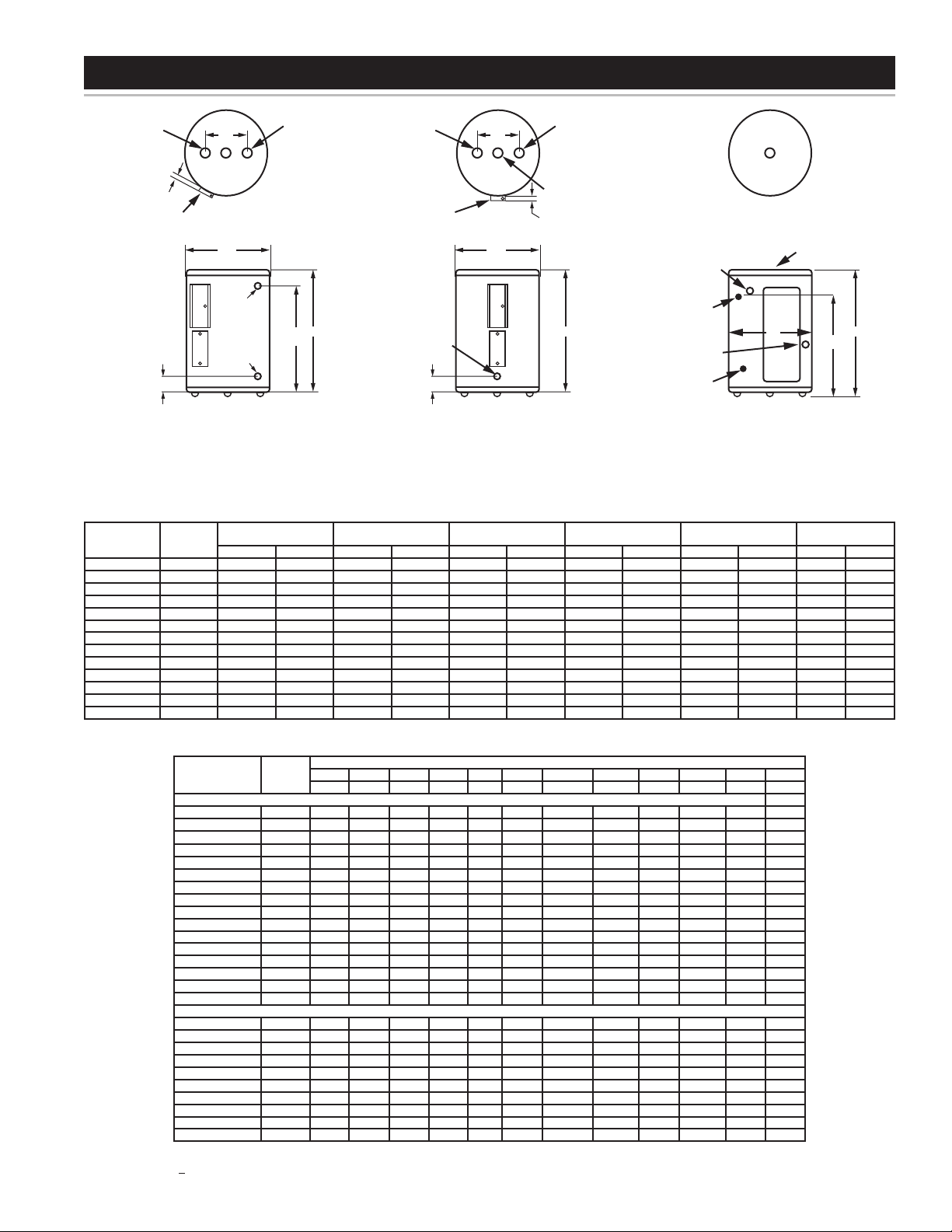
INLET
3/4” (FEMALE)
NPT
OUTLET
3/4” (FEMALE)
NPT
2 1/2”
(63.5 mm)
JUNCTION
BOX
“D”
TOP VIEW
DEL 30/40/50
3 3/4” (95.25 mm)
FRONT VIEW
DEL 30/40/50
3 3/4” NPT
RELIEF VALV E
OPENING
BRASS
DRAIN
VALV E
“B”
“C”
“A”
TOP VIEW
DEL 6/10/15/20
FRONT VIEW
DEN 30-120
3 3/4” (95.25 mm)
DRAIN
VALV E
“B”
“A”
2 1/2”
(63.5 mm)
INLET
3/4” (FEMALE)
NPT
3/4” NPT
RELIEF VALV E
OPENING
OUTLET
3/4” (FEMALE)
NPT
JUNCTION
BOX
“D”
TOP VIEW
DEN 30 - 120
INLET
3/4” (FEMALE)
NPT
OUTLET
3/4” (FEMALE)
NPT
FRONT VIEW
DEL 6/10/15/20
*(NO SIDE OUTLET AVAILABLE FOR DEL-6 MODELS)
3/4” NPT
RELIEF VALV E
OPENING
ALTERNATE OUTLET
3/4” (FEMALE) NPT
ELECTRICAL
CONNECTION
“C”
“A”
“B”
DIMENSIONS AND CAPACITIES DATA
TABLE 2 - RECOVERY CAPACITIES
Element
Wattage
(Upper/Lower)
INPUT
KW
U.S. Gallons/Hr and Litres/Hr at TEMPERATURE RISE INDICATED
F° 36F° 40F° 54F° 60F° 72F° 80F° 90F° 100F° 108F° 120F° 126F°
C° 20C° 22.2C° 30C° 33.3C° 40C° 44.4C° 50C° 55.5C° 60C° 66.6C° 70C°
NON-SIMULATANEOUS
/1500 GPH 17 15 11 10 8 8 7 6 6 5 5
1.5 LPH 64 58 43 38 32 29 26 23 21 19 18
/2000 GPH 23 20 15 14 11 10 9 8 8 7 6
2.0 LPH 85 77 57 51 43 38 34 31 28 26 24
/2500 GPH 28 25 19 17 14 13 11 10 9 8 8
2.5 LPH 107 96 71 64 53 48 43 38 36 32 30
3000/3000 GPH 34 30 23 20 17 15 14 12 11 10 10
3.0 LPH 128 115 85 77 64 58 51 46 43 38 37
4000/4000 GPH 45 41 30 27 23 20 18 16 15 14 13
4.0 LPH 170 153 11 4 102 85 77 68 61 57 51 49
4500/4500 GPH 51 46 34 30 25 23 20 18 17 15 14
4.5 LPH 192 173 128 115 96 86 77 69 64 58 55
5000/5000 GPH 56 51 38 34 28 25 23 20 19 17 16
5.0 LPH 213 192 142 128 107 96 85 77 71 64 61
6000/6000 GPH 68 61 45 41 34 30 27 24 23 20 19
6.0 LPH 256 230 170 153 128 11 5 102 92 85 77 73
SIMULATANEOUS OPERATION
3000/3000 GPH 68 61 45 41 34 30 27 24 23 20 19
6 LPH 256 230 170 153 128 115 102 92 85 77 73
4000/4000 GPH 90 81 60 54 45 41 36 32 30 27 26
8 LPH 341 307 227 205 170 153 136 123 114 102 97
4500/4500 GPH 101 91 68 61 51 46 41 36 34 30 29
9 LPH 384 345 256 230 192 173 153 138 128 115 11 0
5000/5000 GPH 11 3 101 75 68 56 51 45 41 38 34 32
10 LPH 426 384 284 256 213 192 170 153 142 128 122
6000/6000 GPH 135 122 90 81 68 61 54 49 45 41 39
12 LPH 5 11 460 341 307 256 230 205 184 170 153 146
Recovery capacities at 100° F rise equal: for non-simultaneous element operation = 4.1 gal. x KW of one element; for simultaneous element operation = 4.1 gal. x 2/3 KW of
both elements. For other rises multiply element KW as previously explained by 410 and divide by temperature rise. Full load current for single phase = total watts : voltage.
TABLE 1 - ROUGH-IN DIMENSIONS
Models
Dimensions
No. of
Elements
Tank Capacity A B C D
Approx.
Shipping Weight
US Gals. Litres inches mm inches mm inches mm inches mm Lbs. Kg.
DEL-6 1 6 23 15 1/2 394 14 1/4 362 11 279 - - 35 15.9
DEL-10 1 10 38 18 1/4 464 18 457 12 1/2 318 - - 54 24.5
DEL-15 1 15 57 26 660 18 457 20 1/2 521 - - 58 26.3
DEL-20 1 20 76 22 1/4 565 21 3/4 552 15 3/8 391 - - 73 33.1
DEL-30 2 30 114 30 7/8 784 21 3/4 552 24 1/8 613 8 203 100 45.4
DEL-40 2 40 151 32 1/4 819 24 610 25 9/16 649 8 203 125 56.7
DEL-50 2 50 189 32 1/4 819 26 1/2 673 25 1/8 638 8 203 166 75.3
DEN-30 2 30 11 4 34 1/2 876 20 1/2 521 - - 8 203 98 44.5
DEN-40 2 40 151 45 1/8 1146 20 1/2 521 - - 8 203 11 3 51.3
DEN-52 2 50 189 54 7/8 1394 20 1/2 521 - - 8 203 131 59.4
DEN-66 2 66 250 60 3/4 1543 21 3/4 552 - - 8 203 176 79.8
DEN-80 2 80 303 59 3/8 1508 24 610 - - 8 203 2 11 95.7
DEN-120 2 119 450 62 7/16 1586 29 3/8 746 - - 8 203 326 147.9
FIGURE 1
6
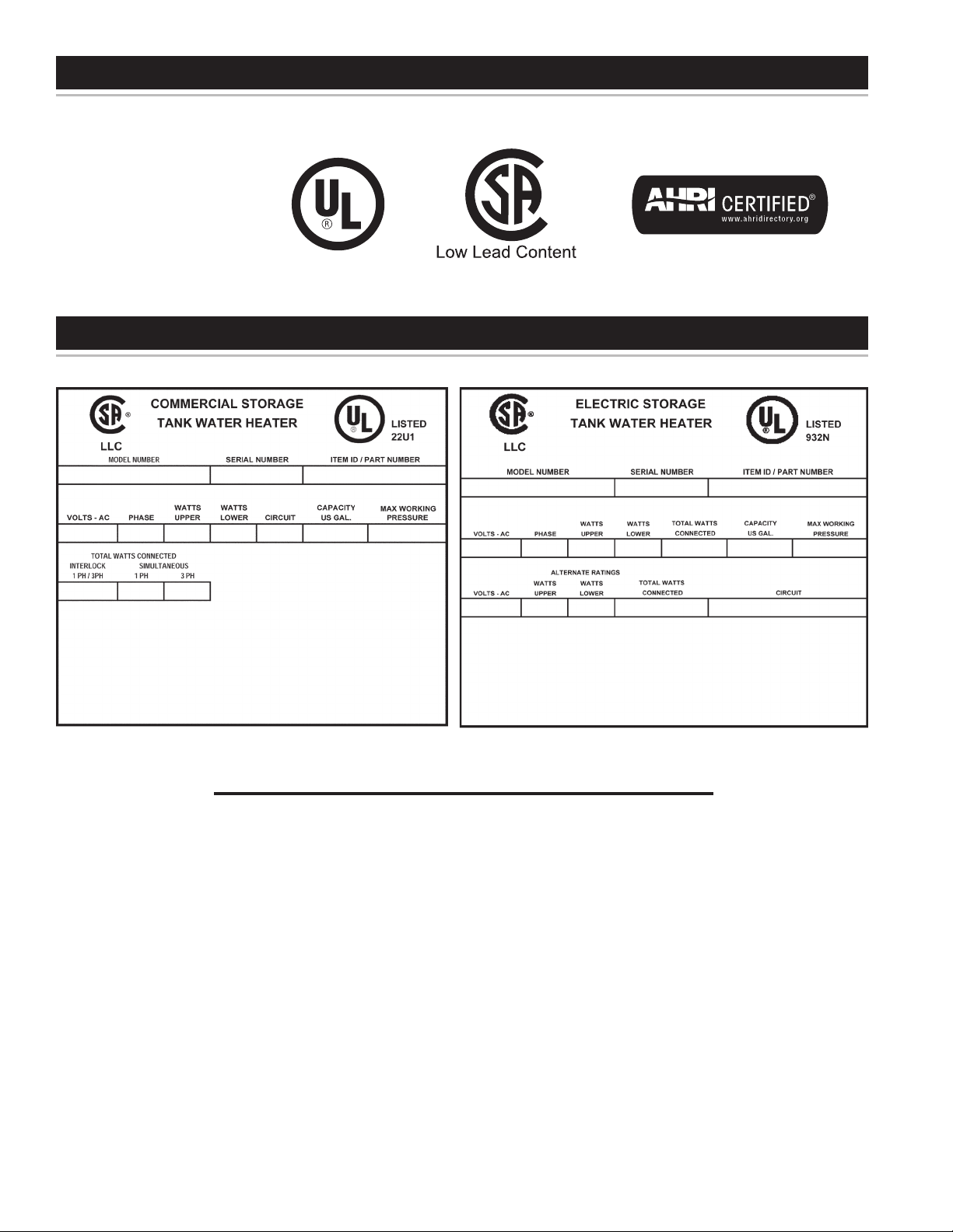
APPROVALS
MODEL AND RATING
DEL-30/40/50 & DEN-30/40/52/66/80/120 DEL-6/10/15/20
All models are listed by
Underwriters Laboratories Inc.
7
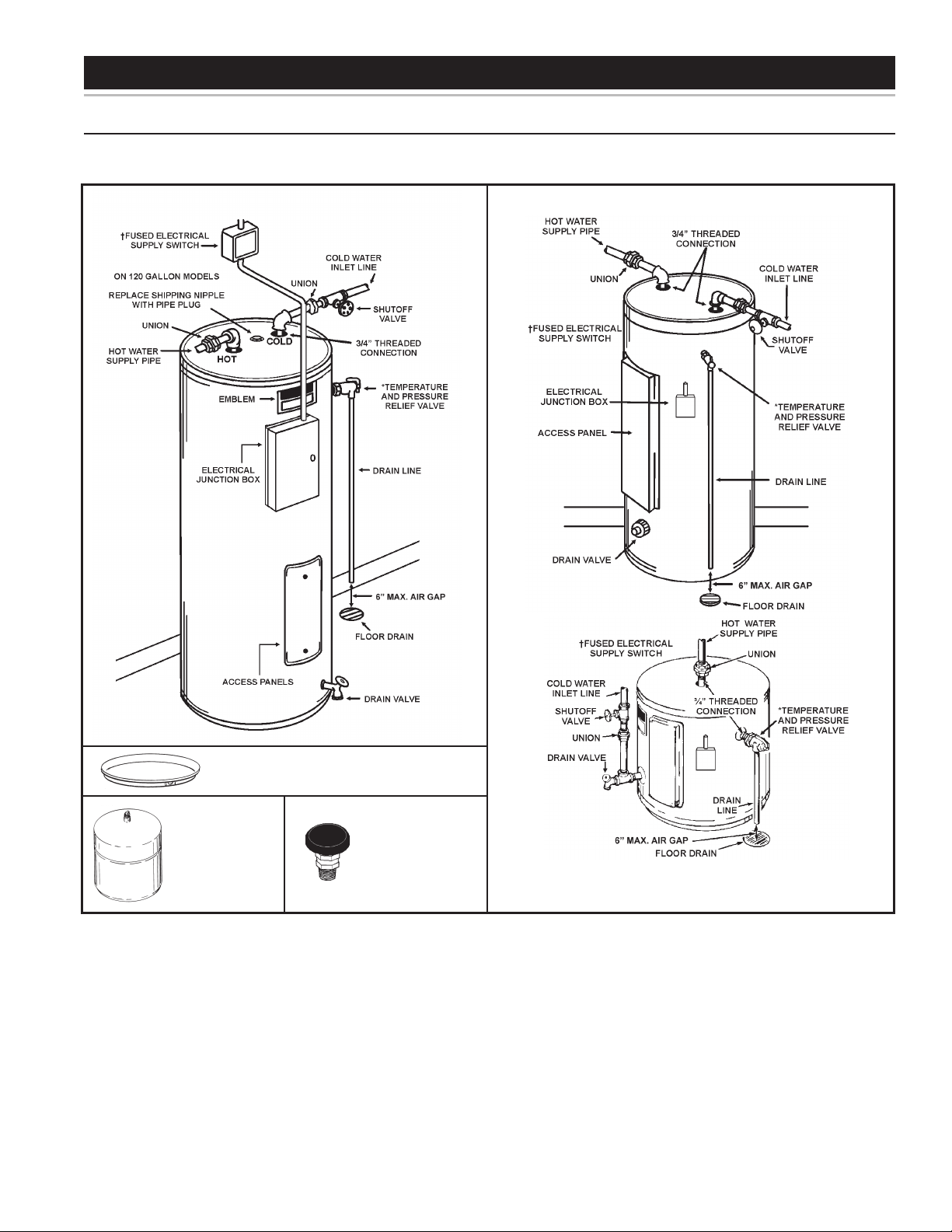
FEATURES AND COMPONENTS
ELECTRONIC CONTROL MODELS
FIGURE 2
This page shows typical water heater installations by model designations.
† OVER CURRENT PROTECTION MUST BE SUPPLIED IN WATER HEATER CIRCUIT.
CONSULT LOCAL CODE OR CURRENT EDITION OF NEC FOR PROPER INSTALLATION.
* INSTALL IN ACCORDANCE WITH ALL LOCAL CODES.
INSTALL VACUUM RELIEF
IN COLD WATER INLET
LINE AS REQUIRED BY
LOCAL CODES.
INSTALL SUITABLE DRAIN PANS UNDER WATER HEATERS
TO PREVENT DAMAGE DUE TO LEAKAGE. REFER TO WATER
HEATER LOCATION ON PAGE 8.
INSTALL THERMAL
EXPANSION TANK
IF CHECK VALVE OR
PRESSURE REDUCING
VALVE IS USED IN
SUPPLY LINE.
DEN/DEL DUAL ELEMENT HEATER
DEN/DEL SINGLE ELEMENT HEATER
8
FACTS TO CONSIDER ABOUT THE LOCATION
The water heater should be located as close as possible
to/or centralized to the water piping system. The water
heater should be located in an area not subject to freezing
temperatures.
The water heater should be located in an area where leakage
of the tank or connections will not result in damage to the area
adjacent to the heater or to lower oors of the structure.
When such locations cannot be avoided, a suitable drain pan
should be installed under the heater.
Such pans should be at least two inches deep, have a
minimum length and width of at least two inches greater
than the diameter of the heater and should be piped to an
adequate drain.
Drain pans suitable for these water heaters are available from
your distributor or A.O. Smith Water Heater Parts Fulllment,
125 Southeast Parkway, Franklin, TN 37068.
LOCATING THE NEW WATER HEATER
Water heater life depends upon water quality, water pressure
and the environment in which the water heater is installed. Water
heaters are sometimes installed in locations where leakage may
result in property damage, even with the use of a drain pan piped
to a drain. However, unanticipated damage can be reduced or
prevented by a leak detector or water shut-off device used in
conjunction with a piped drain pan. These devices are available
from some plumbing supply wholesalers and retailers, and detect
and react to leakage in various ways:
• Sensors mounted in the drain pan that trigger an alarm or turn
off the incoming water to the water heater when leakage is
detected.
• Sensors mounted in the drain pan that turn off the water
supply to the entire home when water is detected in the
drain pan.
• Water supply shut-off devices that activate based on the water
pressure differential between the cold water and how water
pipes connected to the water heater.
• Devices that will turn off the gas supply to a gas water heater
while at the same time shutting off its water supply.
CLEARANCES
A minimum clearance of 4” must be allowed for access to
replaceable parts such as thermostats, drain valve and
relief valve.
Adequate clearance for servicing this water heater should
be considered before installation, such as changing the
anodes, etc.
Loading...