

Page 1

Product Introduction
58 G/64 Gbaud Multichannel PAM4 BERT
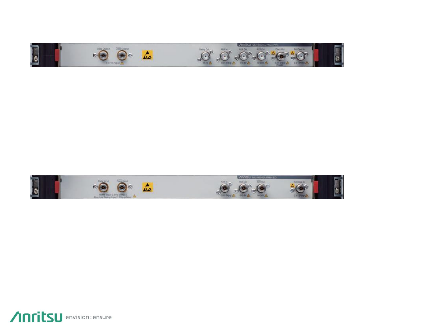
PAM4 PPG MU196020A
PAM4 ED MU196040B
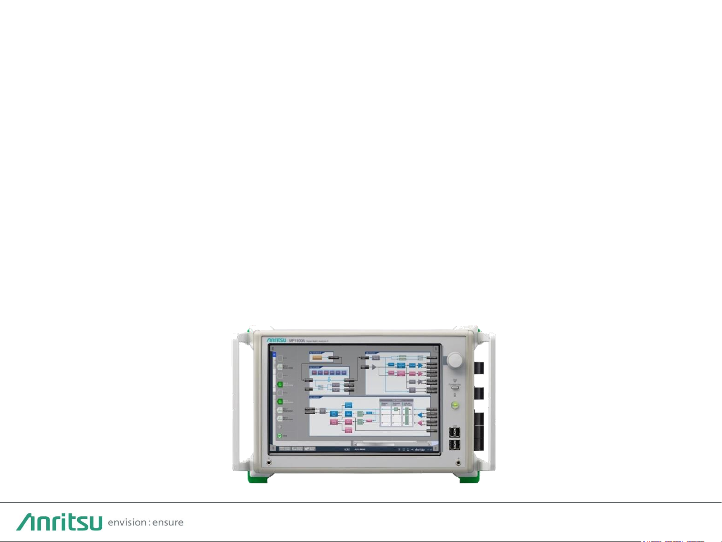
Signal Quality Analyzer-R
MP1900A Series
Page 2
2
• Supports bit error rate measurements optimized for high-speed 400 GbE and
next-generation 800 GbE interfaces
• High-quality data output waveforms up to 64 Gbaud and high input sensitivity
performance provide strong support for testing PAM4 device designs
• All-in-one Jitter Addition, Clock Recovery, Emphasis, NRZ/PAM3/PAM4 Pattern
Editing, SER, FEC functions, etc.
• Easily configured, high-reproducibility PAM4 measurement solution
MP1900A PAM4 Target Applications
200/400/800 GbE, CEI-56G/112G, InfiniBand HDR, 64G Fibre Channel
Outline of MP1900A Series PAM4 BERT
Page 3
3
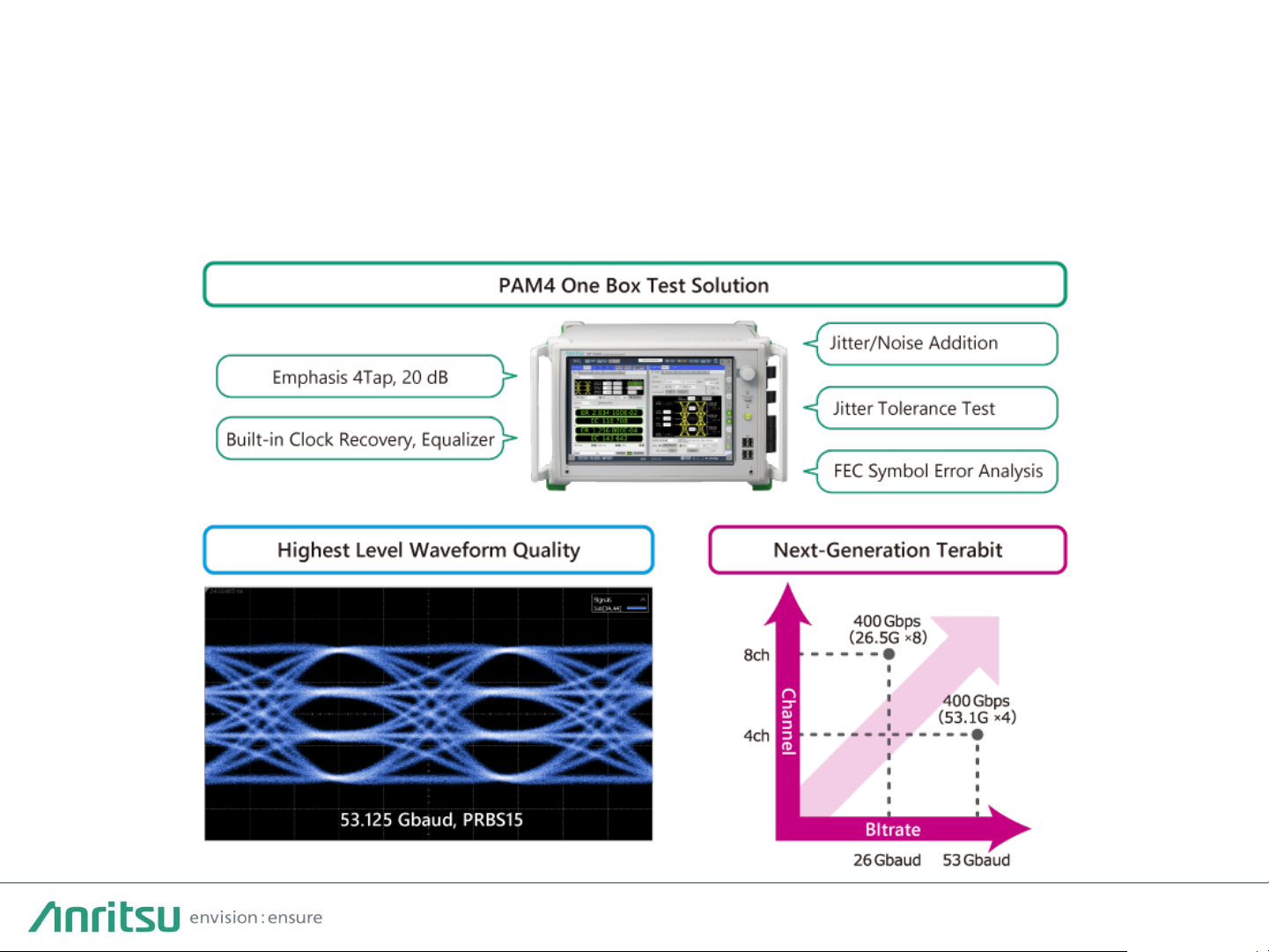
MP1900A PAM4 BERT Features
・All-in-one, high-reproducibility, easily configured test solution
・High-quality waveforms for more accurate measurement
・Easy, low-cost, future-proof expandability supporting high bit rates and multichannels
Page 4
4
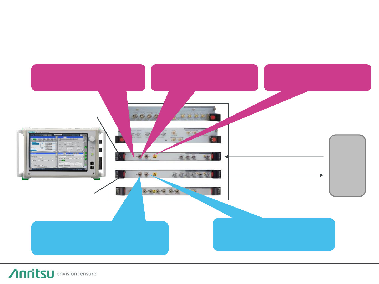
PAM4 All-in-One BERT Solution
DUT
PAM4 PPG
MU196020A
PAM4 ED
MU196040B
Easy-to-use and configure all-in-one solution with high reproducibility,
helping cut test times
No External Equipment, Compact
Module with Built-in PAM4
Functions
High-Quality 64G PAM4
Waveforms with Variable
Emphasis/Linearity Functions
SER/BER/FEC, Capture,
Logging functions
ED w/ Built-in Clock
Recovery and Equalizer
Typ. 36 mV at 53.125 G
High Input Sensitivity
Page 5
5
High-Quality Waveform PAM4 PPG MU196020A
64.2 Gbaud 53.125 Gbaud 26.5625 Gbaud
Differential 1.4 Vp-p, PRBS13Q pattern, J1789A 40-cm cable + 70 GHz Scope
Best-in-class waveform quality with low Intrinsic Jitter (typ. 170 fs (rms) and fast Tr/Tf
(typ. 8.5 ps) for more accurate evaluation of actual DUT performance
Page 6
6
116 Gbit/s PAM4 Best Level High-Sensitivity Input Performance
High sensitivity input of 36 mV (typical at 53.125 Gbaud) simplifies
previously difficult PAM4 error troubleshooting measurements.
PAM4 PPG
MU196020A
PAM4 ED
MU196040B
Error-Free at 53.125 Gbaud
Best level PAM4 sensitivity
Typ. 36 mV EH/ Eye
Page 7
7
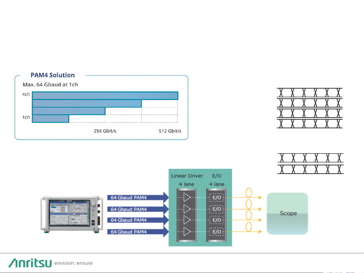
Multichannel Support and Expandability (1/2)
One MP1900A PPG supports up to 4ch for 400 GbE (53 Gbaud x 4 Lanes),
and faster evaluations, helping cut future support upgrade costs.
・4-Lane DUT (Driver + E/O) Measurement Example
・2ch Combination (NRZ)
a1 a2 a3 a4 a5
b1 b2 b3 b4 b5
Ch1
Ch2
Supports shift to “a1b1 a2b2 . . .” pattern
a1 a2 a3 a4 a5
Ch1
Ch2
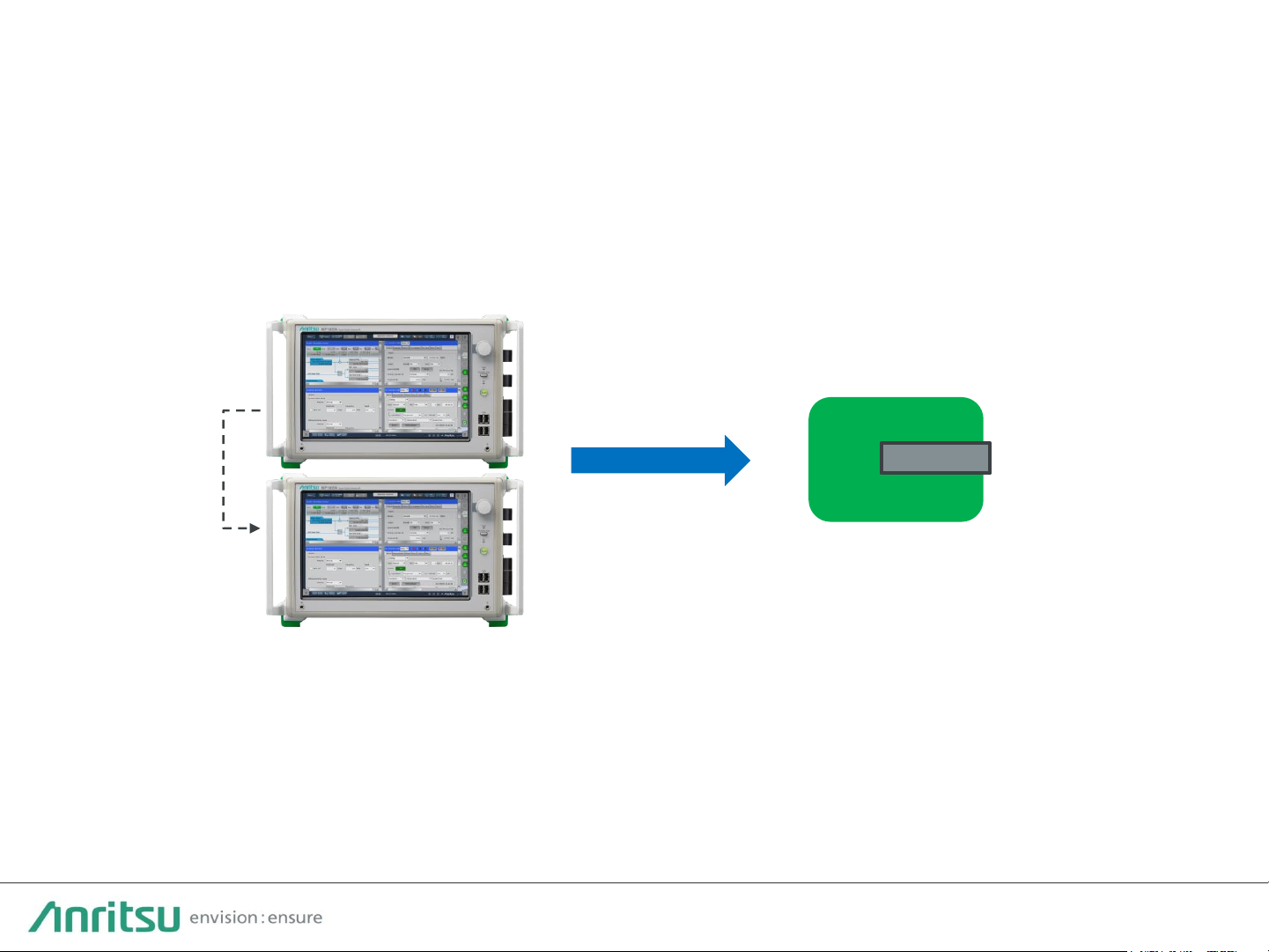
One MP1900A unit supports synchronous output for up
to 4ch; two units support up to 8ch.
*Future support for 8ch
a1 a2 a3 a4 a5
・ Channel Synchronization
Ch3
a1 a2 a3 a4 a5
Ch4
a1 a2 a3 a4 a5
Page 8
8
Multichannel Support and Expandability (2/2)
Expanded support for 800G using 8ch synchronization function
(4ch x 53.125 Gbaud PAM4 x two MP1900A units)
Supports QSFP-DD transceiver FEC evaluation using 8-lane FEC Pattern
Generation function
400G QSFP-DD, OSFP
Optical Transceiver
or
800G Next Generation
Transceiver
Synchronized
8-lane FEC Pattern
Unit Sync.
Control
Page 9
9
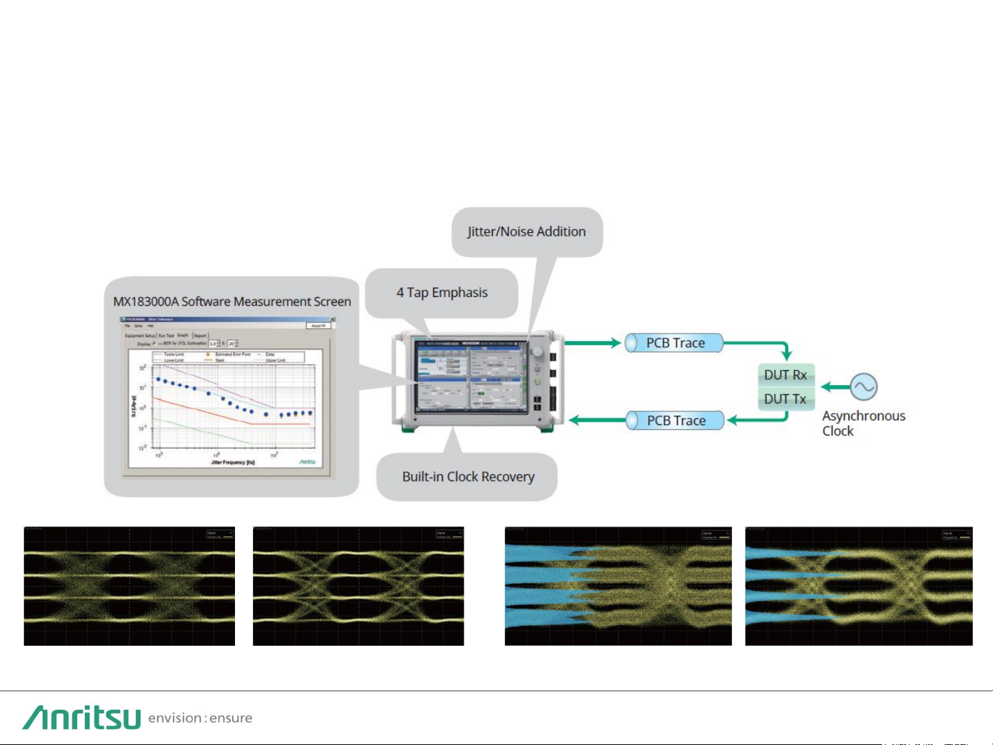
Supports PAM4 Jitter Tolerance test using just one unit. A measurement system
to help cut measurement time is configured easily by combining the Jitter/Noise
Addition function, built-in Clock Recovery function, and Jitter Tolerance
MX183000A-PL001 software.
Jitter Tolerance Measurement Function
Sine-Wave Jitter (SJ) Random Jitter (RJ) CM/DM Noise White Noise
Page 10

10
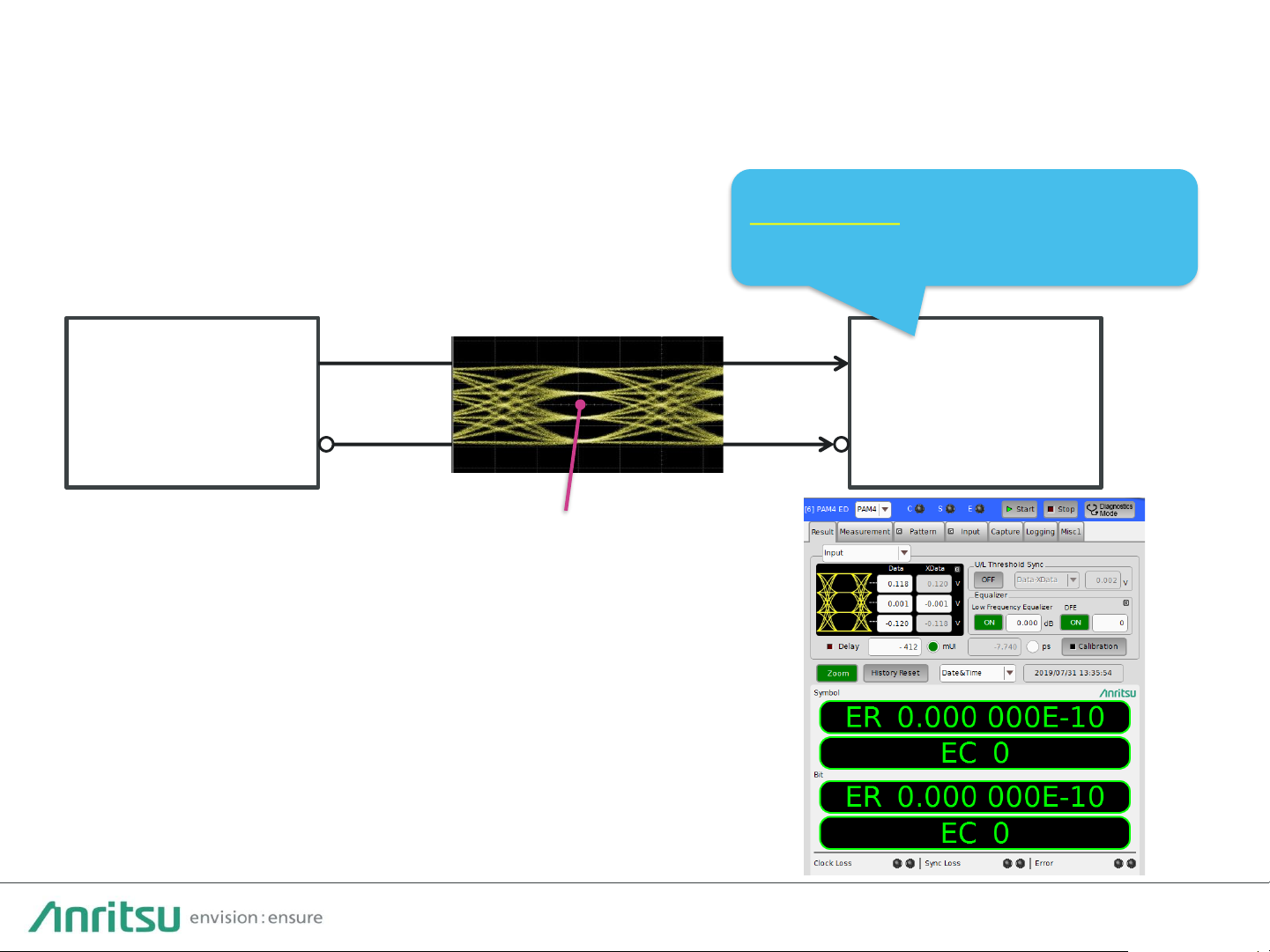
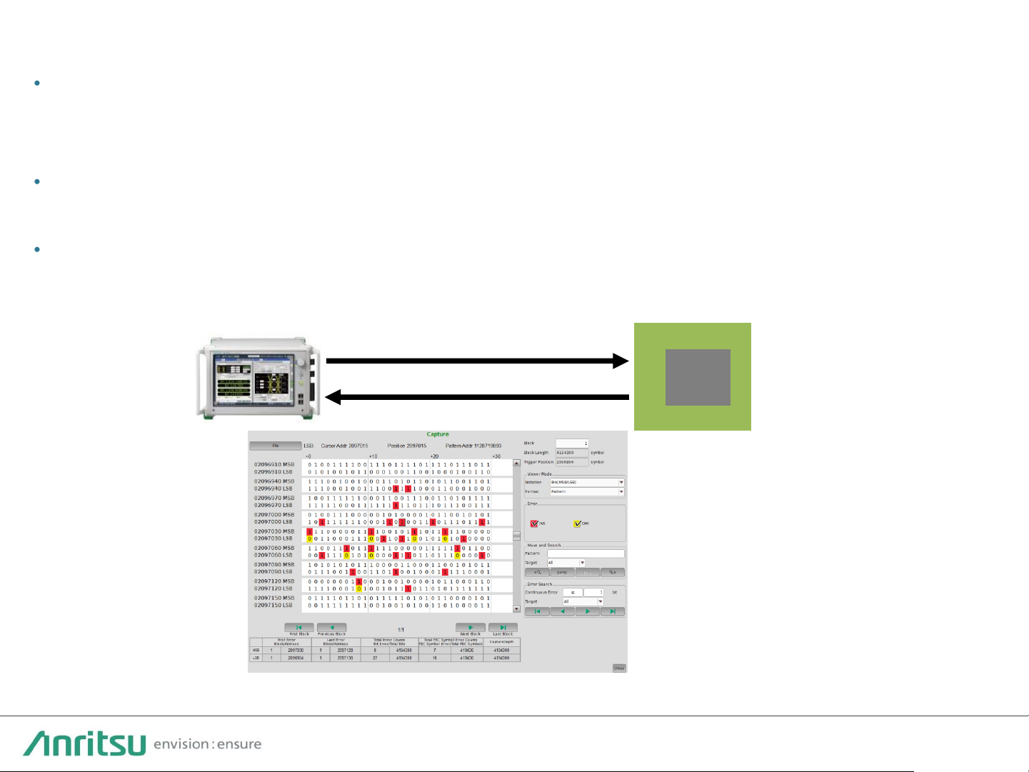
Uncorrectable Codeword and FEC Symbol Errors can be measured and displayed on
one screen in real-time simultaneously with bit error measurements. Measurement of
jitter tolerance and FEC Symbol Error per codeword distribution based on
correctable/uncorrectable FEC is supported (MU196040B-042).
Both bit error and FEC Symbol Errors are measured at high speed.
PAM4 Test Signal
with Jitter
MP1900A
PAM4 BERT
FEC based Jitter Tolerance test (MX183000A-PL001)
FEC Symbol Error Distribution
Real-time FEC Symbol Error Measurement
Real-time FEC Symbol Error and FEC Standard Jitter Tolerance
Measurement Functions
Page 11

11
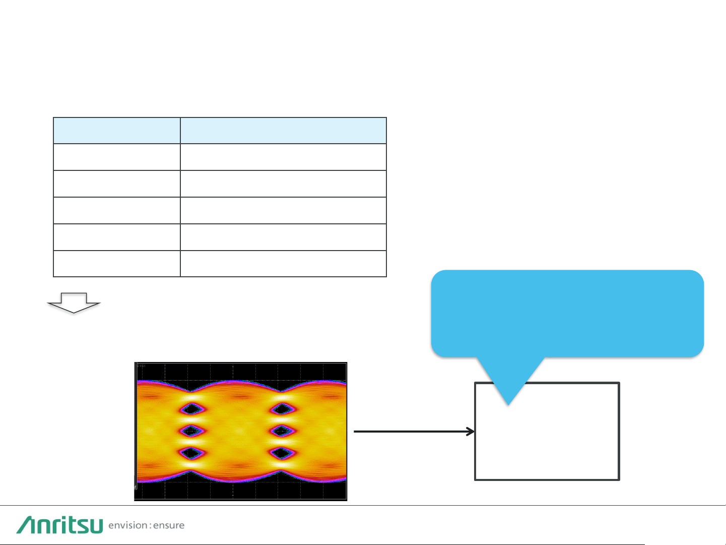
When the DUT has a built-in bit error counter, combination with the MP1900A PPG
makes it easy to configure a highly cost-effective Jitter Tolerance measurement
environment.
Jitter Tolerance Measurement using DUT BER Counter
(MX183000A-PL001 Jitter tolerance software) (MX183000A-PL031 DUT Error Counts Import)
Page 12
12
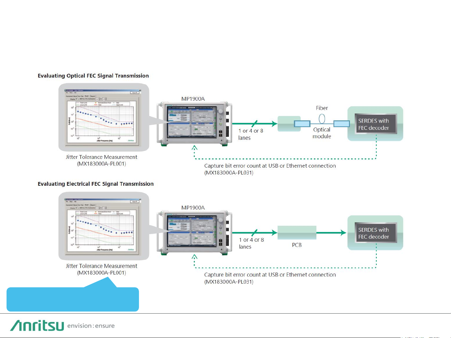
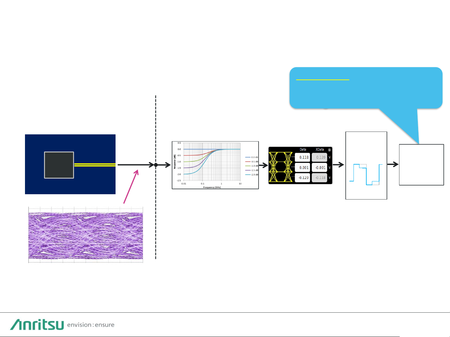
FEC can be evaluated by combining FEC pattern generation with error insertion, and
reading the DUT bit error count.
Multilane FEC Evaluation
Evaluate Jitter Tolerance, etc., using
captured error count
Page 13
13
PAM4 PPG/ED Specifications
PAM4 PPG MU196020A
PAM4 ED MU196040B
• Baud-rate: 2.4 Gbaud to 32.1/58.2/64.2 Gbaud
• Output amplitude: 0.14 Vp-p to 1.6 Vp-p (Differential)
• Emphasis: 4Tap, ±20 dB (1 post/2 pre-cursor), ISI/Channel Emulator
• Intrinsic jitter(rms): 170 fs (typ., NRZ)
• Tr/Tf (20-80%): 8.5 ps (typ., NRZ)
• Multichannel synchronization
• FEC pattern generation
• Baud-rate: 2.4 Gbaud to 32.1/58.2 Gbaud PAM4 and 64.2 Gbaud NRZ
• Input amplitude (max.): 1.0 Vp-p (NRZ, PAM4)
• Input sensitivity(Eye Height) : 23 mV (typ., 26.5625 Gbaud), 36 mV (typ., 53.125 Gbaud)
• Built-in Clock Recovery: 2.4 G to 29 Gbaud or 32.1 Gbaud/ 51 G to 58.2 Gbaud extension
• Analog bandwidth: >40 GHz (nominal)
• Built-in Equalizer: Low Frequency Equalizer(2 dB)+DFE(1.4 dB)
• SER measurement, logic error analysis using Diagnostics Mode, Capture , Logging function
• Real-time FEC Symbol Error measurement, FEC based Jitter Tolerance Test function
Page 14

14
P A M 4 P P G F u n c t i o n s a n d
P e r f o r m a n c e
Page 15
15
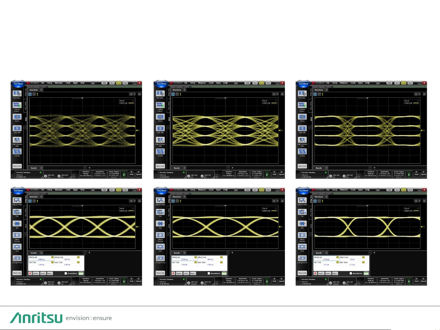
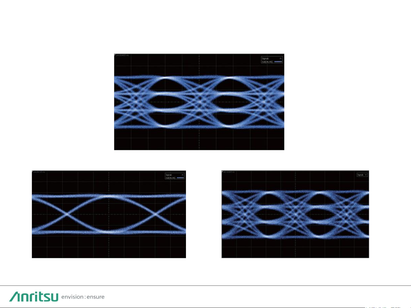
PAM4/NRZ Data Output
Supports next-generation applications over 50 Gbaud, such as 400/800 GbE, CEI-112G,
etc.
53.125 Gbaud PAM4
58 Gbaud NRZ 58 Gbaud PAM4
Typical Output Waveform (J1789A 40-cm Cable, 1400-mV Differential, PRBS15)
Page 16

16
Easy PAM4 Level Control
・PAM4 Total Amplitude setting
・Independent PAM4 3Eye Amplitude
control with voltage and % values
Level Control Reference Waveform
Control Baud Rate, Level, Offset, Half Period Jitter, and Delay from one screen
・Easy return to equal level using
[Even] button
Page 17

17
Linearity and Emphasis Controls
53G, Linearity control
53G, Post1 Emphasis control
53G, Pre1 Emphasis control
Supports TOSA device evaluations and stressed input tests using various channel
insertion losses
TOSA
Scope
MU196020A
PAM4 PPG
Page 18
18
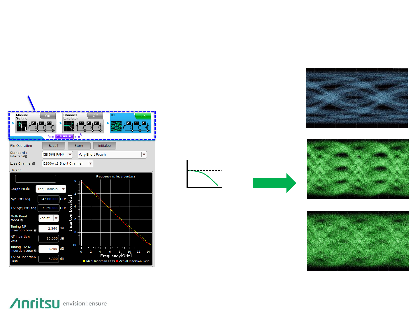
ISI, Channel Emulator
Shorter development period by eliminating need for multiple test PC boards with
simple and high-reproducibility design tests of high-speed device channel loss
dependency
Emulates Channel Loss
or
Generates Loss
Calibration Signal
(ISI option)
f
S21
・Manual Setting: Correct signal for target Eye Height/Width using 10Tap Emphasis function
・Channel Emulator: Emulate S2P and S4P loss insertion, and perform Emphasis compensation
・ISI: Emulate ISI using CEI-28G/25G Nyquist frequency loss setting
NRZ CEI-28G 14-dB Loss
PAM4 26.6G 4-dB Loss
PAM4 26.6G 6-dB Loss
Typical ISI Function Waveforms
Page 19

19
PAM4 Test Patterns (1/2)
Supports PAM4 test patterns specified by 200 and 400 GbE standards
Supported Test Patterns
CEI
QPRBS13
-CEI, QPRBS31-CEI
IEEE
IEEE802.3bs/cd: PRBS13Q, PRBS31Q, SSPRQ, Square Wave
IEEE802.3bj: QPRBS13, JP03A, JP03B, Transmitter Linearity
RS
-FEC RS-FEC Scrambled Idle 50G 1 Lane (26.5625 Gbaud, 50GBASE-KR/CR/SR/FR/LR)
RS-FEC Scrambled Idle 100G 1 Lane (53.125 Gbaud, 100GBASE-DR/KR1/CR1)
RS-FEC-Int Scrambled Idle 100G 1 Lane(53.125 Gbaud, 100GBASE-P)
RS-FEC Scrambled Idle 100G 2 Lanes 26.5625 Gbaud, 100GBASE-KR2/CR2/SR2)
RS-FEC Scrambled Idle 200G 4 Lanes (26.5625 Gbaud, 200GBASE-SR4/DR4/FR4/LR4)
RS-FEC Scrambled Idle 200G 2 Lanes(53.125 Gbaud, 200GBASE-KR2/CR2)
RS-FEC Scrambled Idle 400G 4 Lanes (53.125 Gbaud, 400GBASE-DR4/KR4/CR4)
RS-FEC Scrambled Idle 400G 8 Lanes (26.5625 Gbaud, 400GBASE-FR8/LR8)
InfiniBand
PRBS13Q (InfiniBand), PRBS23Q, PRBS31Q(InfiniBand)
Fibre Channel
PRBS31Q (Fibre Channel)
General Purpose
PRBS7
, 9, 10, 11, 13, 15, 20, 23, 31, Data (User defined) 4 to 256 Msymbol
Edit Data pattern using PAM4 symbol 0, 1, 2, and 3 values.
Page 20

20
• BER measurement for different pattern generation methods depending on DSPs
• Efficient detection of pattern generation circuit differences as well as logic errors,
such as inverted logic and bit skew
Pattern
Generation
Set bit skew between MSB and LSB
Gray Coding
1/(1+D) Mod4
Pre-Coding
MSB and LSB Inverted Logic
(before/after Gray Coding)
PAM4 Test Patterns (2/2)
Page 21

21
PAM4 Error Insertion Function
With PAM4, not only do errors occur at single level changes, there are also cases
where double level changes occur due to MSB errors.
Using the [Error Addition] tab to insert errors in each of these cases helps confirm
communications and inspection of error results.
00 → 01
01 → 00
10 → 11
11 → 10
00 → 10
01 → 11
10 → 00
11 → 01
・LSB Error Insertion ・MSB Error Insertion
Page 22

22
Using
80-cm cable
@53G
Using
40-cm cable
@53G
← J1789A 40-cm cable best for
evaluating this waveform
Closed Eye opening with long
cable (ex. 80-cm cable)
↓ Can automatically calibrate
settings for effect of 80-cm cable
Cable Settings for Monitoring
Select J1790A
cable setting
Adjusts Emphasis to automatically correct loss of 80-cm cable connecting separate DUT
Cable for data output setting: J1789A 0.4 m
Cable for data output setting: J1789A 0.4 m Cable for data output setting: J1790A 0.8 m
Page 23

23
P A M 4 E D F u n c t i o n s a n d
P e r f o r m a n c e
Page 24

24
Outline of 116-Gbit/s PAM4 Error Detector for 400 GbE/800 GbE
• High-performance BERT for 116-Gbit/s PAM4 error-free measurement
Simplify previously difficult PAM4 error troubleshooting
• Industry-best high input sensitivity of 36 mV EH@53.125 Gbaud
Support more accurate evaluations up to 116-Gbit/s PAM4.
• All-in-one 58-Gbaud PAM4 receiver test solution with built-in Clock
Recovery and Equalizer functions
Support faster testing and debugging with easy measurement system
configuration
• Wideband operation: 2.4 Gbaud to 64.2 Gbaud for NRZ
2.4 Gbaud to 58.2 Gbaud for PAM4
• Support CEI-112G-VSR Stressed Receiver Input Test
• Built-in 58-Gbaud PAM4 Clock Recovery
• PAM4 symbol Capture function
• Multichannel measurement (up to 4ch/unit)
• Real-time FEC Symbol Error measurement, FEC based Jitter Tolerance test
Target Applications: 100/200/400/800 GbE, CEI-112G-VSR
Page 25

25
All-in-One BERT w/ PAM4 Built-in Clock Recovery & Equalizer
Connections with external equipment and components are eliminated.
PAM4 Jitter Tolerance measurements are simplified by the easy system
configuration.
PAM4 PPG
MU196020A
PAM4 ED
MU196040B
w/built-in
CR&EQ
・Jitter
・ISI Control
DUT
・Built-in Clock Recovery to re-time DUT
signal for 58-Gbaud PAM4 JTOL testing
・Equalizer function to open Eye of VSR
stressed signal for measuring BER
Support PAM4
Jitter Tolerance test
Support BER measurement of
closed-Eye signal with stress
Page 26
26
CEI-112G-VSR Stressed Input Test Support
The true DUT low-error-rate Rx performance can be tested with added stress.
Item Spec. (112G-VSR-PAM4)
Baud Rate
36 to
58 Gbaud
Channel
Loss
12 dB at 26.5625 GHz
EH6
>37 mV
EW6
>0.2 UI (>3.76 ps)
Target
BER
<E
-6
CEI-112G-VSR Rx input specification
Using MU196020A PPG output and ISI board
as calibrated signal (oscilloscope CTLE 2.5 dB
setting) supporting Rx Input standard
performance
PAM4 ED
MU196040B
Higher sensitivity performance
(E-8 or lower) than receiver
model defined by CEI VSR
standard (E-6)
Page 27
27
Built-in Equalizer
DUT
Low-frequency Equalizer
ISI Stressed eye signal
MU196040B
Built-in Equalizer diagram
BER
Measur
ement
Combination of built-in Equalizer function and high input sensitivity
performance supports higher accuracy measurements.
Error-Free at 53.125 Gbaud
for inputting signals path
through 3 dB loss (typ.).
DFE
Decision feedback
Equalizer
Page 28

28
Real-time FEC Symbol Error Measurement
Uncorrectable Codeword, FEC Symbol Error, and Bit Error measurement results
on one screen
MSB/LSB Errors and Codeword Counts and Rate for
each Symbol Error Count on Details Screen
MU196040B PAM4 ED Result Screen
Page 29
29
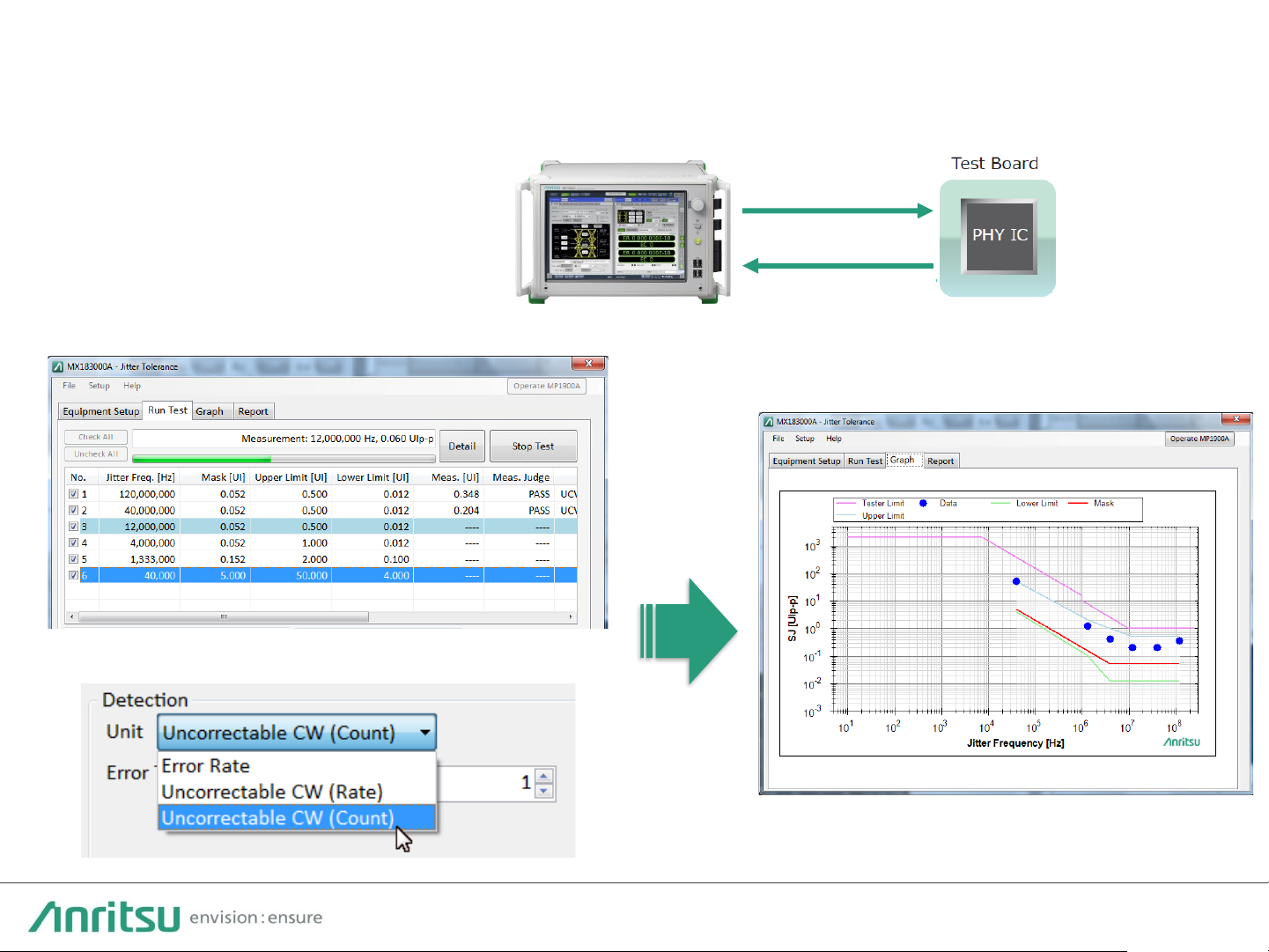
Jitter Tolerance Measurements Based on FEC Symbol Errors
PAM4 Test Signal
with Jitter
MP1900A PAM4 BERT
Jitter Frequency and Test Mask Settings
Test Criterion Setting, Bit Error or Uncorrectable Codeword
Start Test
Correctable Error Jitter Tolerance Test Result
One-button jitter tolerance
measurement is supported
based on whether or not error
correction using FEC is possible.
Page 30
30
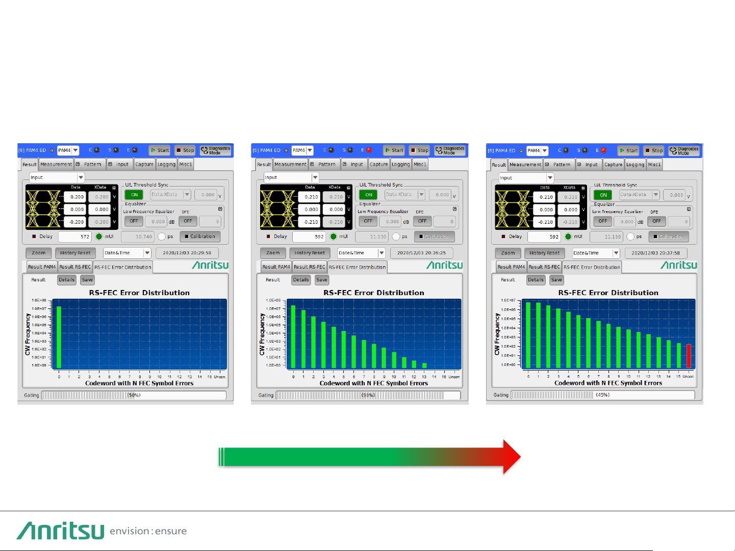
FEC Symbol Error Distribution in Real-time
Error Free Correctable Errors Uncorrectable Errors
Stress Injection
Supports FEC Symbol Error Distribution function.
Monitor changes in input signal conditions, such as jitter stress, in real-time.
Page 31
31
FEC Symbol Capture Function (1/2)
High input sensitivity performance of 36 mV EH at 53 Gbaud plus FEC Symbol
Capture function for Pre-FEC jitter tolerance evaluation and analysis of FEC
uncorrectable errors
FEC Symbol Error detection for IEEE802.3-defined RS-FEC Codeword length and
FEC Symbol length standards
Input signal capture at timing exceeding settable FEC Symbol error threshold
(1 to 32 per step), and Input Pattern Analysis function for causes of errors exceeding
the threshold
Jitter Stressed Signal
Capturing Detected FEC Symbols Errors
Test Board
SERDES/
Transceiver
MP1900A PAM4 BERT
RX
TX
Page 32

32
FEC Symbol Capture Function (2/2)
Detect FEC Symbol Errors in Codeword.
The input data is captured when the number of FEC
symbol errors exceeds the threshold setting. The
causes of FEC-uncorrectable errors can be analyzed
from the captured data.
15 Errored FEC Symbols
Detect!
Errored Codeword
544 FEC Symbols
544 FEC Symbols
544 FEC Symbols
1Errored FEC Symbol 2 Errored FEC Symbol
un-errored Codeword
un-errored Codeword
un-errored Codeword
1Errored FEC Symbol
Page 33

33
Bathtub Jitter Analysis Function
The input signal jitter and phase margin can be measured automatically using the
Bathtub function.
The wideband and high-sensitivity PAM4 ED helps more accurate measurement of
DUT performance.
Example of PAM4 Signal Bathtub Measurement
Page 34

34
Error Analysis Function (1/2)
Useful measurement of both symbol errors (MU196040B-041) and bit errors for
specifying error causes by comparing both measurement results
Press [Details] for more detailed analysis by confirming results for 12 error types.
PAM4 bit-error measurement results
Separate error-rate measurements for MSB and LSB
Simultaneous measurement of 12 error
types
Page 35

35
The Diagnostics Mode is useful for troubleshooting logic errors, such as inverted logic
and MSB/LSB bit skew, etc. When these types of logic errors prevent synchronization,
the cause can be determined using the separate MSB and LSB error results and the bit
skew result between MSB and LSB.
MSB/LSB bit skew detection
Separate MSB and LSB error results
Error Analysis Function (2/2)
Diagnostics Mode button
Page 36

36
PAM4 Symbol Capture Function
Capture function supports identification of PAM4 error symbols and cuts
verification time.
Start capturing
inputting symbols
using Error detection,
Match pattern, or
External trigger.
Can specify error symbol position and
level change of captured signal
Page 37

37
Measurement Result Logging Function
Periodic saving of BER/SER, etc., measurement results can evaluate
changes and stability of DUT time-dependent performance.
Sets measurement cycle and starts logging
Saves results to file
Measurement item selection
Times-periodically saved measurement results
Page 38

38
A p p e n d i x
Page 39

39
Typical Configuration of 64 G PPG/58 G ED
Model Name
J1789A Electrical Length Specified cable (0.4m, Vconnector)
J1790A Electrical LengthSpecifiedcable (0.8m, V connector)
J1800A ISI Board V
J1793A
Pick OFF Tee(V)
Model Name
MX183000A-PL001 Jitter Tolerance Test
MX183000A-PL031 DUT Error Counts Import
Model Name Option Qty Remark
MP1900A Signal Quality Analyzer-R
-
1
MU181000B 12.5GHz 4 port Synthesizer
-
1
MU181500B Jitter Modulation Source
-
1
For jitter injection
MU196020A PAM4 PPG
002,
011, 040, 042
1
MU196040B PAM4 ED
002,
011, 021, 023, 041, 042
1
Software for jitter tolerance test
Optional parts
Page 40

40
64 G PPG/58 G ED Module Option
Model Name
MU196040B PAM4 ED
MU196040B-001 32G baud
MU196040B-002
58G baud
(max.64.2Gbit/sNRZ/58.2Gbaud PAM4)
MU196040B-011 Equalizer
MU196040B-021
29G Clock Recovery
(2.4 G to 29 Gbaud)
MU196040B-022
32G Clock Recovery
(2.4 G to 32.1 Gbaud)
MU196040B-023
58G Clock Recovery Extension
(51 Gto 58 Gbaud)
MU196040B-041 SER Measurement
MU196040B-042 Jitter Analysis
Model Name
MU196020A PAM4 PPG
MU196020A-001 32G baud
MU196020A-002 58G baud
MU196020A-003 64G baud
MU196020A-011 4Tap Emphasis
MU196020A-030 Data Delay
MU196020A-040 Adjustable ISI
MU196020A-042 FEC Pattern Generation
MU196020A-050
Intel-Module
Synchronization
Page 41

41
PAM4 PPG MU196020A Specifications
Item Specification Remarks
Operation Rate
2.4 Gbaud to 32.1/58.2/64.2
Gbaud
Option selection
Signal format
NRZ, PAM4
N
umber of Outputs
2 (Data, xData)
Output Amplitude
70 mVp
-p to 800 mVp-p (Single-end)
140 mVp
-p to 1600 mVp-p (Differential)
Offset
–
2 V to +3.3 V
Emphasis
4 Tap,
–20 to +20 dB
Option
Channel Emulator
Generates waveform with insertion loss and simulates
waveform with corrected insertion loss
Set by loading S
-Parameter file (S2P, S4P)
Option
ISI
Simulates ISI generation waveform
Set using loss (
–8.00 to 8.00 dB) at CEI-specified Nyquist frequency
Used in combination with channel board, such as J1800A/J1758A (optional
accessories parts), or Noise Module MU195050A
Option
Independently Variable
PAM4 3 Eye
20% to 50% (PAM4 Amplitude 0/3 level = 100%)
PAM4 Pattern
SSPRQ, PRBS13Q, PRBS31Q, RS
-FEC, etc.
Option for RS
-FEC
PAM4 Pattern Error Addition
MSB Error, LSB Error, LSB&MSB Error, RS
-FEC Symbol Error
Option for RS
-FEC
Tr/Tf (20% to 80%)
8.5 ps (typ., NRZ)
Random Jitter
170 fs rms (typ., NRZ)
I/O Connector
V (f)
Jitter Addition Function
SJ, RJ, BUJ, SSC (
with MU181500B)
Noise Addition Function
CMI, DMI, White Noise (
with MU195050A (32.1G max.) and J1792A)
Page 42
42
PAM4 ED MU196040B Specifications
Item Specification Remarks
Baud rate
2.4
Gbaud to 32.1 / 64.2 Gbaud (NRZ)
2.4
Gbaud to 32.1 / 58.2 Gbaud (PAM4)
Select upper limit as
option
Input Signal format
NRZ, PAM4
N
umber of Inputs
2 (Data, xData)
Input Amplitude
1.0
Vp-p (max.)
Input Sensitivity
36 mV (typ. at
53.125 G),
23 mV (typ. at
26.5625 G) (Eye Height of each PAM4 Eye)
Stressed Margin
BER < 1 E
-8 (When inputting minimum eye signal defined in CEI-
112G
-VSR)
Analog Band
>40 GHz (nominal)
Clock Recovery
Operation Range
2.4
Gbaud to 29 Gbaud or 2.4 Gbaud to 32.1 Gbaud
51
Gbaud to 58.2 Gbaud Extension
Option
Equalizer
DFE
(1.4 dB) + Low-frequency-Equalizer (2 dB)
Option
BER/SER
Measurement
Total BER, MSB/LSB BER, SER
Logging, Capture
(8 M bits/4 M PAM4 symbols)
Option for SER
FEC Symbol Error
measurement
Uncorrectable
Codeword Error, FEC Symbol Error,
RS
-FEC Error Distribution
Option
Patterns
PRBS, Data
(max. 268 Mbit (symbol)),
PAM4 Pattern (PRBS13Q, PRBS31Q, SSPRQ, QPRBS13
-CEI,
QPRBS31
-CEI), Gray Code/PAM4 Pre-Code, RS-FEC pattern
Option for RS
-FEC
pattern
Connector
V (f)
Page 43
43
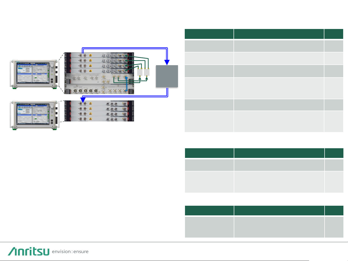
Typical 100G x 4 Multichannel Configuration
Model Name Qty
MP1900A Signal Quality Analyzer-R
1
MU181000B 12.5GHz 4 port Synthesizer
1
MU181500B Jitter Modulation Source
1
MU196020A PAM4 PPG (Opt. 002,011, 030, 040,
042, 050)
4
J1748A Power Splitter (1.5G-18GHz) 2
J1728A Electrical Length Specified Coaxial
Cable(0.4m, K)
6
DUT
Unit1
Model Name Qty
MP1900A Signal Quality Analyzer-R
1
MU196040B PAM4 ED (Opt. 002, 011, 021, 023,
041, 042)
4
Unit2
Unit1
Unit2
Model Name Qty
J1789A or
J1790A
Electrical Length Specified cable
0.4 m or 0.8m (V connector)
16
Test cable
Page 44

44
PAM4 Test Patterns
PRBS13Q, PRBS31Q, SSPRQ:
PAM4 patterns defined by IEEE802.3bs, 802.3cd 200 GbE, and 400 GbE standards
QPRBS13-CEI:
Pattern for Tx output measurement and Rx input calibration defined by CEI-56G PAM4 standard
JP03A:
“0303…” pattern string for evaluating transmitter RJ
JP03B:
Pattern (shown below) of 62 symbols composed of string of 15 contiguous “03” followed by 16 contiguous “30” for evaluating
transmitter Even-Odd jitter
03030303030303030303030303030330303030303030303030303030303030
Square:
“3333333300000000” pattern string for OMA evaluation of optical interfaces (OMA: Optical Modulation Amplitude)
Transmitter Linearity Test Pattern:
Pattern of 160 symbols with following sequence of 10 PAM4 symbols repeated in 16UI lengths
{0, 1, 2, 3, 0, 3, 0, 3, 2, 1}
The newest specification for the Linearity Test uses a PRBS13Q pattern.
RLM= min((3 x ES1), (3 x ES2), (2 – 3 x ES1), (2 – 3 x ES2)) (120D-5)
V
mid
= (V0+ V3)/2, ES1 = (V1– V
mid
)/(V0– V
mid
), ES2 = (V2– V
mid
)/(V3– V
mid
)
Gray-xxxx:
PAM4 signals use four levels to express 2-bit pairs, but sometimes a 2-bit change such as 01→10 may be detected incorrectly for
one level. To prevent this, a Gray code (00→00, 01→01, 10→11, 11→10) is used as the pattern at the Tx side.
Page 45

2021-2 MJM No. MP1900A_64G-E-L-1-(8.00)
 Loading...