

Page 1

MX100003A
Scenario Edit
Environment Kit
Operation Manual
Second Edition
●
For safety and warning information, please read this
manual before attempting to use the equipment.
●
Additional safety and warning information is provided
within the MT1000A Transport Modules Operation
Manual, MT1000A Network Master Pro OTDR Modules
Operation Manual, MT1100A Network Master Flex
Operation Manual, or MT1040A Transport Modules
Operation Manual. Please also refer to them before
using the equipment.
●
Keep this manual with the equipment.
ANRITSU CORPORATION
Document No.: M-W4042AE-2.0
Page 2
Safety Symbols
DANGER
WARNING
CAUTION
To prevent the risk of personal injury or loss related to equipment malfunction, Anritsu Corporation uses the following
safety symbols to indicate safety-related information. Ensure that you clearly understand the meanings of the
symbols BEFORE using the equipment. Some or all of the following symbols may be used on all Anritsu equipment.
In addition, there may be other labels attached to products that are not shown in the diagrams in this manual.
Symbols used in manual
This indicates a very dangerous procedure that could result in serious injury or
death if not performed properly.
This indicates a hazardous procedure that could result in serious injury or death if
not performed properly.
This indicates a hazardous procedure or danger that could result in light-to-severe
injury, or loss related to equipment malfunction, if proper precautions are not taken.
Safety Symbols Used on Equipment and in Manual
The following safety symbols are used inside or on the equipment near operation locations to provide information
about safety items and operation precautions. Ensure that you clearly understand the meanings of the symbols and
take the necessary precautions BEFORE using the equipment.
This indicates a prohibited operation. The prohibited operation is indicated
symbolically in or near the barred circle.
This indicates an obligatory safety precaution. The obligatory operation is indicated
symbolically in or near the circle.
This indicates a warning or caution. The contents are indicated symbolically in or
near the triangle.
This indicates a note. The contents are described in the box.
These indicate that the marked part should be recycled.
MX100003A
Scenario Edit Environment Kit
Operation Manual
21 July 2020 (First Edition)
5 March 2021 (Second Edition)
Copyright © 2020-2021, ANRITSU CORPORATION.
All rights reserved. No part of this manual may be reproduced without the prior written permission of the
publisher.
The operational instructions of this manual may be changed without prior notice.
Printed in Japan
ii
Page 3

Equipment Certificate
Anritsu Corporation guarantees that this equipment was inspected at
shipment and meets the published specifications.
Anritsu Warranty
● During the warranty period, Anritsu Corporation will repair or exchange this
software free-of-charge if it proves defective when used as described in the
operation manual.
● The warranty period is 6 months from the purchase date.
● The warranty period after repair or exchange will remain 6 months from
the original purchase date, or 30 days from the date of repair or exchange,
depending on whichever is longer.
● This warranty does not cover damage to this software caused by Acts of
God, natural disasters, and misuse or mishandling by the customer.
In addition, this warranty is valid only for the original equipment purchaser. It
is not transferable if the equipment is resold.
Anritsu Corporation shall assume no liability for damage or financial loss of
the customer due to the use of or a failure to use this equipment, unless the
damage or loss is caused due to Anritsu Corporation’s intentional or gross
negligence.
Anritsu Corporation Contact
In the event of this equipment malfunctions, please contact an Anritsu
Service and Sales office. Contact information can be found on the last page
of the printed version of this manual, and is available in a separate file on the
PDF version.
iii
Page 4

This product and its manuals may require an Export License/Approval by
the
country.
Before re-exporting the product or manuals, please contact us to confirm
whether they are export
When you dispose of export
ts/manuals need
to be broken/shredded so as not to be unlawfully used for military
purpose.
Notes On Export Management
Government of the product's country of origin for re-export from your
-controlled items or not.
-controlled items, the produc
iv
Page 5

Software End-User License Agreement (EULA)
Please carefully read and accept this Software End-User License Agreement (hereafter this EULA)
before using (includes executing, copying, installing, registering, etc.) this Software (includes programs,
databases, scenarios, etc., used to operate, set, etc., Anritsu electronic equipment, etc.). By using this
Software, you shall be deemed to have agreed to be bound by the terms of this EULA, and Anritsu
Corporation (hereafter Anritsu) hereby grants you the right to use this Software with the Anritsu
specified equipment (hereafter Equipment) for the purposes set out in this EULA.
Article 1. Grant of License and Limitations
1. You may not to sell, transfer, rent, lease, lend,
disclose, sublicense, or otherwise distribute
this Software to third parties, whether or not
paid therefor.
2. You may make one copy of this Software for
backup purposes only.
3. You are not permitted to reverse engineer,
disassemble, decompile, modify or create
derivative works of this Software.
4. This EULA allows you to install one copy of
this Software on one piece of Equipment.
Article 2. Disclaimers
To the extent not prohibited by law, in no
event shall Anritsu be liable for direct, or any
incidental, special, indirect or consequential
damages whatsoever, including, without
limitation, damages for loss of profits, loss of
data, business interruption or any other
commercial damages or losses, and damages
claimed by third parties, arising out of or
related to your use or inability to use this
Software, unless the damages are caused due
to Anritsu’s intentional or gross negligence.
Article 3. Limitation of Liability
1. If a fault (bug) is discovered in this Software,
failing this Software to operate as described
in the operation manual or specifications
even though you have used this Software as
described in the manual, Anritsu shall at its
own discretion, fix the bug, or replace the
software, or suggest a workaround,
free-of-charge, provided, however, that the
faults caused by the following items and any
of your lost or damaged data whatsoever
shall be excluded from repair and the
warranty.
i) If this Software is deemed to be used for
purposes not described in the operation
manual or specifications.
ii) If this Software has been used in
conjunction with other
non-Anritsu-approved software.
iii) If this Software or the Equipment has
been modified, repaired, or otherwise
altered without Anritsu's prior
approval.
iv) For any other reasons out of Anritsu's
direct control and responsibility, such
as but not limited to, natural disasters,
software virus infections, or any devices
other than this Equipment, etc.
2. Expenses incurred for transport, hotel, daily
allowance, etc., for on-site repairs or
replacement by Anritsu engineers
necessitated by the above faults shall be
borne by you.
3. The warranty period for faults listed in
Section 1 of this Article shall be either 6
months from the date of purchase of this
Software or 30 days after the date of repair
or replacement, whichever is longer.
v
Page 6

Article 4. Export Restrictions
You shall not use or otherwise export or
re-export directly or indirectly this Software
except as authorized by the laws and
regulations of Japan and the United States,
etc. In particular, this Software shall not be
exported or re-exported (a) into any Japan or
US embargoed countries or (b) to anyone
restricted by the Japanese export control
regulations, or the US Treasury
Department's list of Specially Designated
Nationals or the US Department of
Commerce Denied Persons List or Entity
List. In using this Software, you warrant
that you are not located in any such
embargoed countries or on any such lists.
You also agree that you will not use or
otherwise export or re-export this Software
for any purposes prohibited by the Japanese
and US laws and regulations, including,
without limitation, the development, design
and manufacture or production of missiles or
nuclear, chemical or biological weapons of
mass destruction, and conventional weapons.
Article 5. Change of Terms
Anritsu may change without your approval
the terms of this EULA if the changes are for
the benefit of general customers, or are
reasonable in light of the purpose of this
EULA and circumstances of the changes. At
the time of change, Anritsu will inform you of
those changes and its effective date, as a
general rule 45
website, or in writing or by e-mail.
days, in advance on its
Article 6. Termination
1. Anritsu may terminate this EULA
immediately if you violate any conditions
described herein. This EULA shall also be
terminated immediately by Anritsu if there
is any good reason that it is deemed difficult
to continue this EULA, such as your
violation of Anritsu copyrights, patents, etc.
or any laws and ordinances, or if it turns out
that you belong to an antisocial organization
or has a socially inappropriate relationship
with members of such organization.
2. You and Anritsu may terminate this EULA
by a written notice to the other party 30 days
in advance.
Article 7. Damages
If Anritsu suffers any damages or loss,
financial or otherwise, due to your violation
of the terms of this EULA, Anritsu shall have
the right to seek proportional damages from
you.
Article 8. Responsibility after Termination
Upon termination of this EULA in
accordance with Article 6, you shall cease all
uses of this Software immediately and shall
as directed by Anritsu either destroy or
return this Software and any backup copies,
full or partial, to Anritsu.
Article 9. Negotiation for Dispute
Resolution
If matters of interpretational dispute or
items not covered under this EULA arise,
they shall be resolved by negotiations in good
faith between you and Anritsu.
Article 10. Governing Law and Court of
Jurisdiction
This EULA shall be governed by and
interpreted in accordance with the laws of
Japan without regard to the principles of the
conflict of laws thereof, and any disputes
arising from or in relation to this EULA that
cannot be resolved by negotiation described
in Article 9 shall be subject to and be settled
by the exclusive agreed jurisdiction of the
Tokyo District Court of Japan.
Revision History:
February 29th, 2020
vi
Page 7

Prior to the software installation
When using this software
Use antivirus software.
This software may not operate normally if any of the following operations
are performed
running any software other than that recommended or
For how to turn off the functions, refer to the
with your computer.
Protection Against Computer Virus Infections
Before installing this software or any other software recommended or
approved by Anritsu, run a virus scan on your computer, including
removable media (e.g. USB flash drive and CF memory card) you
want to connect to your computer.
and connecting with the measuring instrument
● Copying files and data
On your computer, do not save any copies other than the following:
- Files and data provided by Anritsu
- Files created by this software
- Files specified in this document
Before copying these files and/or data, run a virus scan, including
removable media (e.g. USB flash drive and CF memory card).
● Connecting to network
Connect your computer to the network that provides adequate
protection against computer viruses.
● Protection against malware (malicious software such as viruses).
To connect your computer to network, the following is advised.
- Activate Firewall.
- Install important updates of Windows.
-
Cautions on Proper Operation of Software
● Simultaneously
approved by Anritsu
● Closing the lid (Laptop computer)
● Turning on the screen saver function
● Turning on the battery-power saving function (Laptop computer)
on your computer:
operation manual that came
vii
Page 8

viii
Page 9

About This Manual
This operation manual explains the operation of the MX100003A
Scenario Edit Environment Kit.
For the operation of the Network Master, refer to the following operation
manual.
MT1000A Transport Modules Operation Manual (M-W3933AE)
MT1000A Network Master Pro OTDR Modules Operation Manual
(M-W3810AE)
MT1100A Network Master Flex Operation Manual (M-W3735AE)
MT1040A Transport Modules Operation Manual (M-W4038AE)
For the SCPI commands, refer to the following operation manual.
MT1000A Network Master Pro MT1100A Network Master Flex Remote
Scripting Operation Manual (M-W3736AE)
MT1000A Network Master Pro OTDR Modules Remote Scripting
Operation Manual (M-W3859AE)
MT1000A/MT1100A/MT1040A Remote Scripting Operation Manual
(M-W4041AE)
This manual assumes that readers has the following knowledge.
●
How to operate the Network Master
●
Basic of software programming
Experience of programming (using C or BASIC etc.)
Knowledge of variable, subroutine, IF sentence, etc.
●
Operation on Microsoft Windows
Able to operate the mouse (click, drag, drop), file (load, copy), etc.
I
Page 10

Table of Contents
About This Manual ............................................... I
Outline of
Scenario Edit Environment Kit
1.1 Outline ........................................................................... 1-2
1.2 Operating Environment ................................................. 1-4
......... 1-1
Chapter 2 Installation and Uninstallation ........ 2-1
2.1 Installation ..................................................................... 2-2
2.2 Uninstallation ................................................................ 2-5
Operation .......................................... 3-1
3.1 Starting and Exiting ....................................................... 3-2
3.2 Explanation of the Window ........................................... 3-3
3.3 Connecting with the Network Master ............................ 3-8
3.4 Editing the Scenario ...................................................... 3-9
3.5 Checking the Scenario Contents ................................ 3-36
Chapter 4 Running the Scenario ...................... 4-1
4.1 Copying the Scenario Files ........................................... 4-2
4.2 Registering and Running the Scenario ......................... 4-3
4.3 Result Files ................................................................... 4-9
II
Page 11

2 3
1
Appendix A Syntax of Script ........................... A-1
Appendix B Command Reference ................... B-1
Appendix C Error Messages ............................ C-1
Appendix D Loop Processing .......................... D-1
4
Appendix
III
Page 12

IV.
Page 13

Outline of Scenario Edit Environment Kit
Outline of Scenario Edit Environment Kit
This section outlines the operation environment and functions of
MX100003A Scenario Edit Environment Kit (hereinafter referred to as
“MX100003A”).
1.1
Outline ........................................................................... 1-2
1.2 Operating Environment ................................................. 1-4
1
1-1
Page 14
MT1000A
MT1100A
Network Master Flex
MX100003A
Scenario Edit
Environment
Scenario file
Scenario file
MT9083/MT9085 Series
ACCESS Master
Chapter 1 Outline of Scenario Edit Environment Kit
1.1 Outline
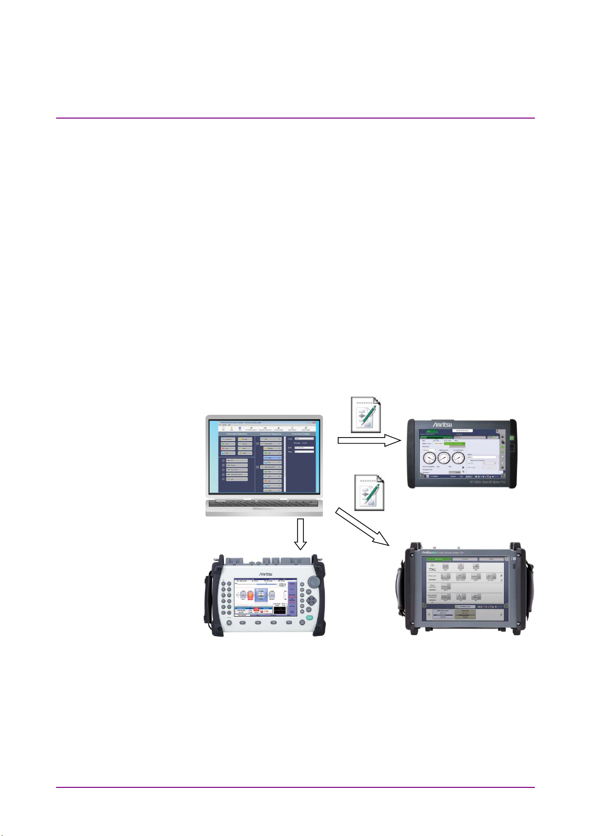
MX100003A is the editing software of the scenario which runs on the
following products.
●
MT1000A Network Master Pro
●
MT1040A Network Master Pro
●
MT1100A Network Master Flex
●
MT9083/MT9085 Series ACCESS Master
Scenario is the program which describes the following:
the process order of the commands and applications (sequence), the
pass/fail thresholds values, the loading file name, and the saving file
names.
By running the scenario created by MX100003A on the Network Master,
the test automation will be realized.
Kit
Figure 1.1-1 Use of MX100003A
Network Master Pro
MT1040A
Network Master Pro
1-2
Features
●
Sequence can be edited by the drag & drop operation.
●
Allows to edit the file stored in the Network Master by connecting to
the Network Master via Ethernet.
●
The scenario can be described by using the SCPI command used for
remote controlling of the Network Master.
Page 15

1.1 Outline
Outline of Scenario Edit Environment Kit
●
Editing the script by using the test command allows creating the
scenario which is suitable measurement method or judgement
condition to your purpose.
MX100003A can load the scripts from the file created by the text editor
such as Note Pad of Windows.
1
1-3
Page 16

OS
Microsoft Windows 7, 8, 8.1
64 bit
Display
1024 × 768 or more
Chapter 1 Outline of Scenario Edit Environment Kit
1.2 Operating Environment
The following table shows the operating environment of MX100003A.
Table 1.2-1 Operating Environment
Item Specifications
32 bit or 64 bit
Microsoft Windows 10
1-4.
Page 17

Installation and Uninstallation
Chapter 2 Installation and Uninstallation
This chapter describes the installation and uninstallation of MX100003A,
using examples when the OS of the personal computer (hereafter, PC) is
Windows 7.
2.1
Installation ..................................................................... 2-2
2.2 Uninstallation ................................................................ 2-5
2
2-1
Page 18
Chapter 2 Installation and Uninstallation
2.1 Installation
Install the MX100003A by the following procedure.
When NET Framework 4.6 is not installed in the PC
1. Copy MX100003A_xxx.zip (xxx is replaced by the version name) to
PC.
2. Double-click the copied zip file to the PC.
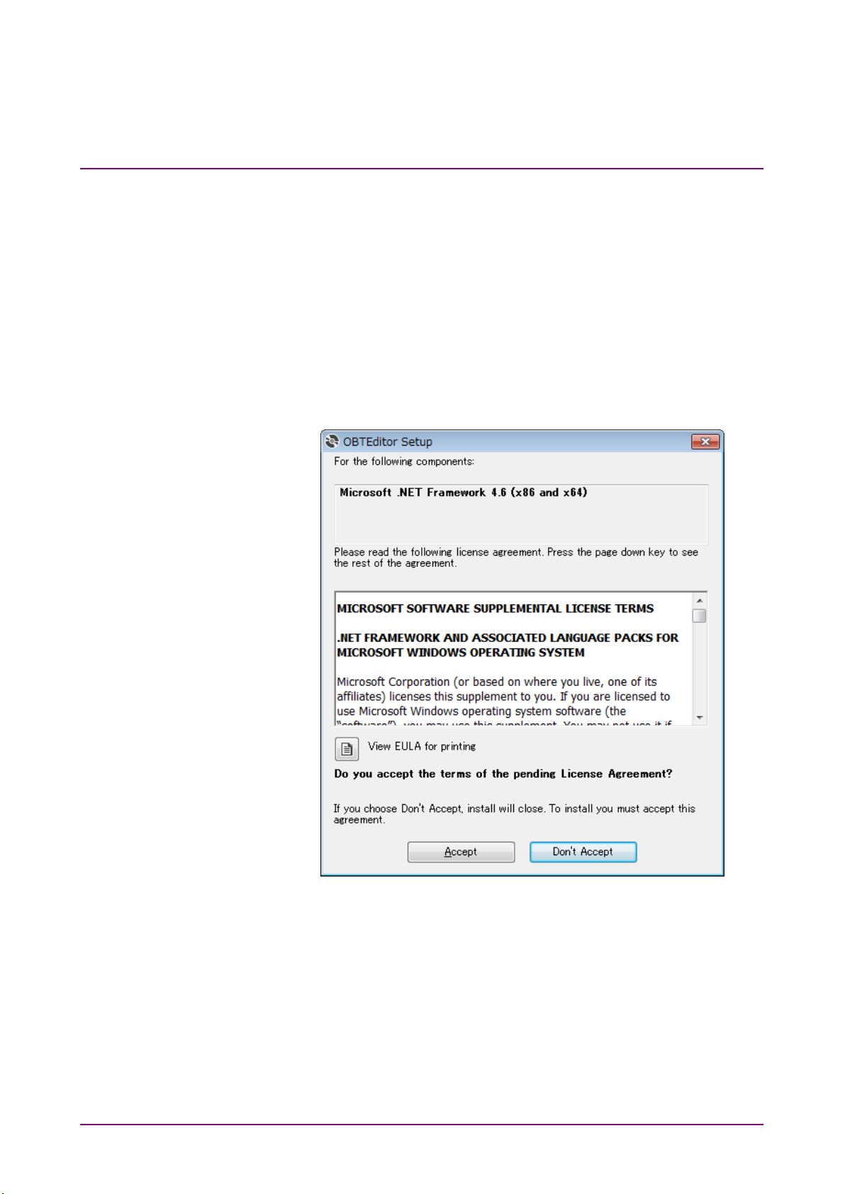
3. Double-click “Setup.exe” in the uncompressed folder. Double-click
the “Setup.exe” in the extracted folder.
4. The following dialog box appears. Click
Accept.
2-2
Page 19
Installation and Uninstallation
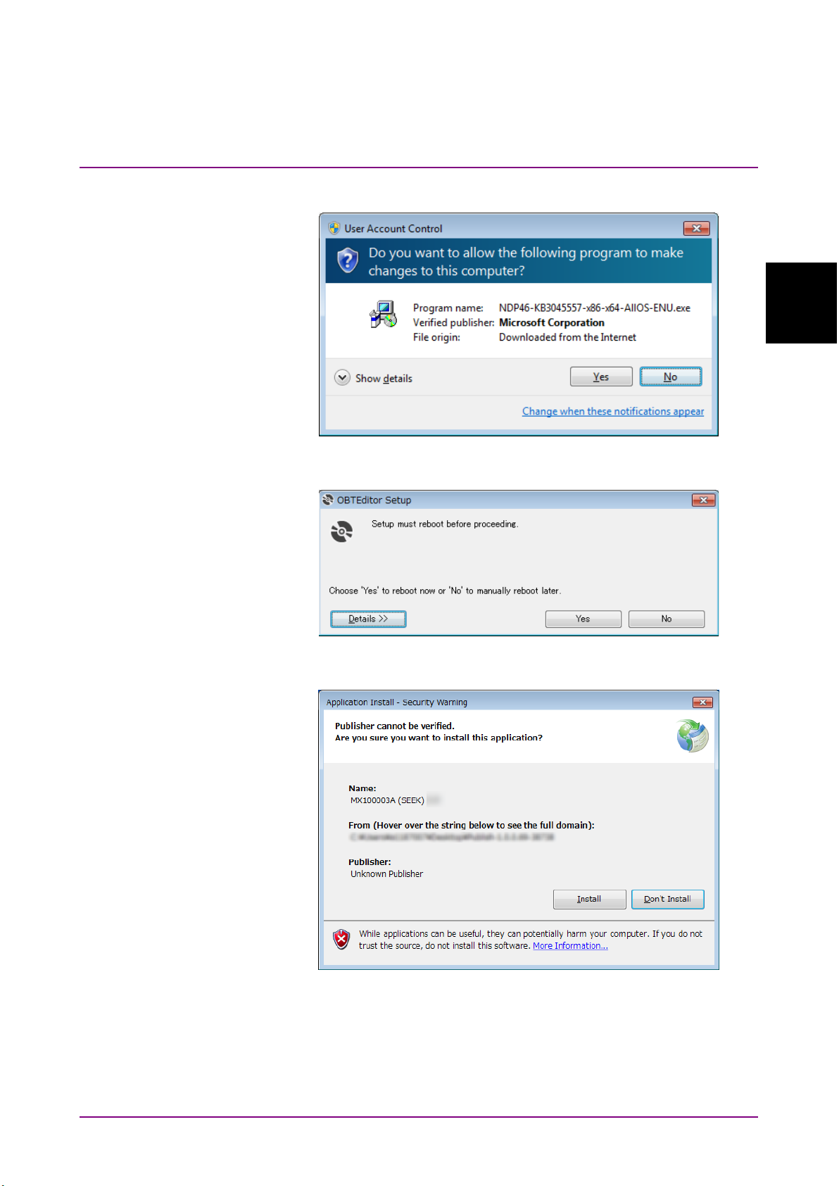
5. The following dialog box appears. Click Yes.
2.1 Installation
2
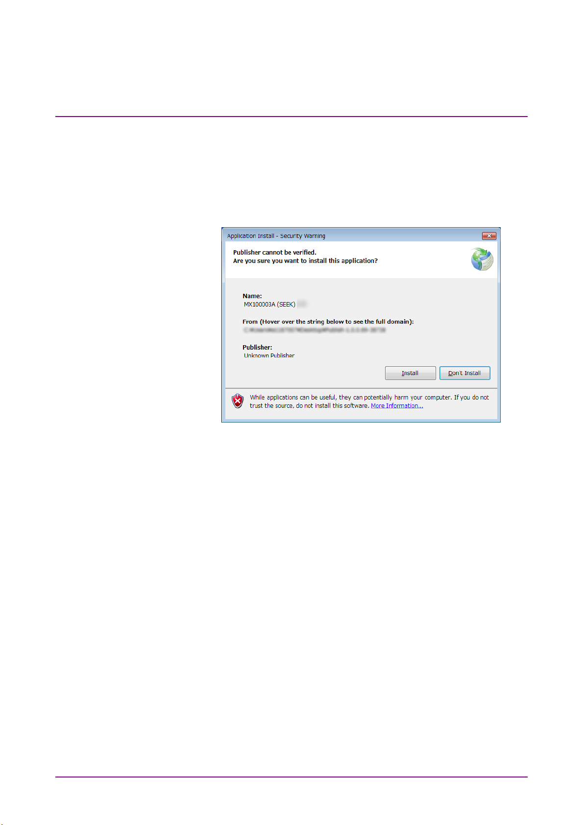
6. The following dialog box appears. Click
7. After PC reboots, the following dialog box appears. Click
Yes .
Install.
The MX100003A window appears after the installation has finished.
2-3
Page 20
Chapter 2 Installation and Uninstallation
When NET Framework 4.6 is installed in the PC
1. Copy MX100003A_xxx.zip (xxx is replaced by the version name) to
PC.
2. Double-click the copied zip file to the PC.
3. Double-click “Setup.exe” in the uncompressed folder. Double-click
the “Setup.exe” in the extracted folder.
4. Click
has finished.
Install. The MX100003A window appears after the installation
2-4
Page 21

Installation and Uninstallation
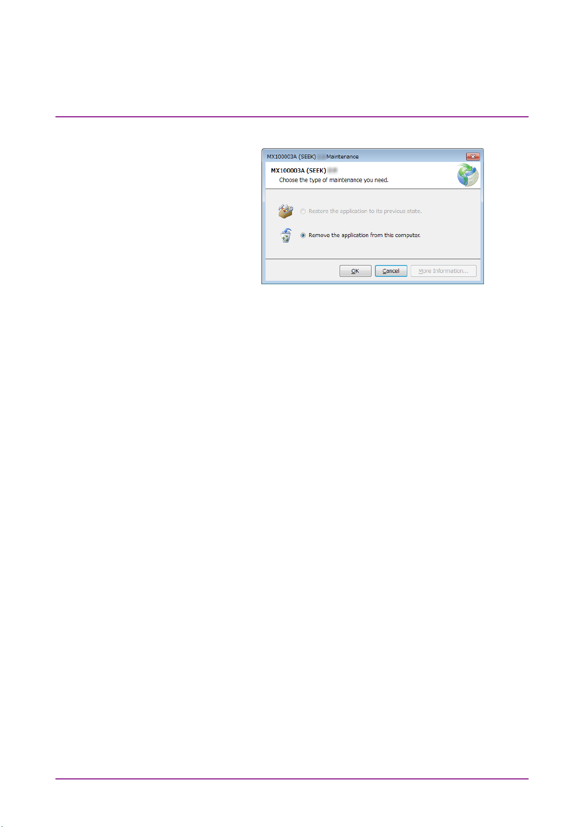
2.2 Uninstallation
This section describes the procedure for uninstalling MX100003A.
2.2 Uninstallation
1. Select
2. Click
3. Click
Control Panel in the Start menu to open the Control Panel.
Uninstall a program.
2
MX100003A (SEEK) in the list, and click Uninstall/Change.
2-5
Page 22
Chapter 2 Installation and Uninstallation
4. Click OK on the following dialog box.
2-6.
Page 23

Operation
This chapter explains the operations of the MX100003A.
3.1
Starting and Exiting ....................................................... 3-2
3.1.1 How to Start the Software ................................ 3-2
3.1.2 How to Exit the Software .................................. 3-2
3.2 Explanation of the Window ........................................... 3-3
3.2.1 Window Configurations .................................... 3-3
3.2.2 Menu ................................................................. 3-4
3.2.3 Toolbar ............................................................. 3-5
3.2.4 Command Selections ....................................... 3-5
3.2.5 Application Selections ...................................... 3-7
3.2.6 Command Sequence ........................................ 3-7
3.2.7 Command Details ............................................. 3-7
3.3 Connecting with the Network Master ............................ 3-8
3.4 Editing the Scenario ...................................................... 3-9
3.4.1 Instrument Configuration .................................. 3-9
3.4.2 Scenario Settings ........................................... 3-11
3.4.3 Report Settings ............................................... 3-13
3.4.4 Global Variables ............................................. 3-14
3.4.5 Editing the Sequence ..................................... 3-16
3.4.6 Editing the Application .................................... 3-21
3.4.7 Editing the Command ..................................... 3-22
3.4.8 Editing Scenario Settings for
MT9083/MT9085 ............................................ 3-35
3.5 Checking the Scenario Contents ................................ 3-36
3
Operation
3-1
Page 24
Chapter 3 Operation
3.1 Starting and Exiting
This section describes startup procedure and exit procedure of the
MX100003A.
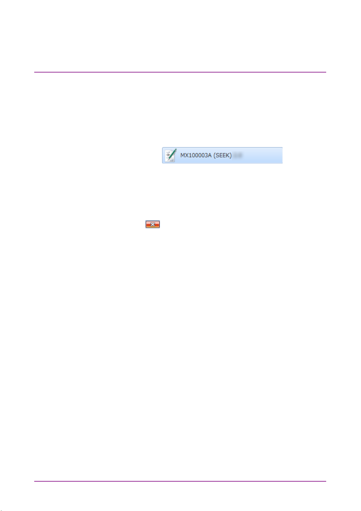
3.1.1 How to Start the Software
Click Start Menu, and click MX100003A (SEEK).
Figure 3.1.1-1 The Button on the Start Menu
3.1.2 How to Exit the Software
Exit the MX100003A by one of following operation.
● Click
● Click at right-top of the window.
If the scenario on the way of editing has not saved, confirming message
appears.
Yes : Exits with saving the scenario.
No: Exits without saving the scenario.
Cancel: Cancels exiting the MX100003A.
Close on the File menu.
3-2
Page 25
Operation
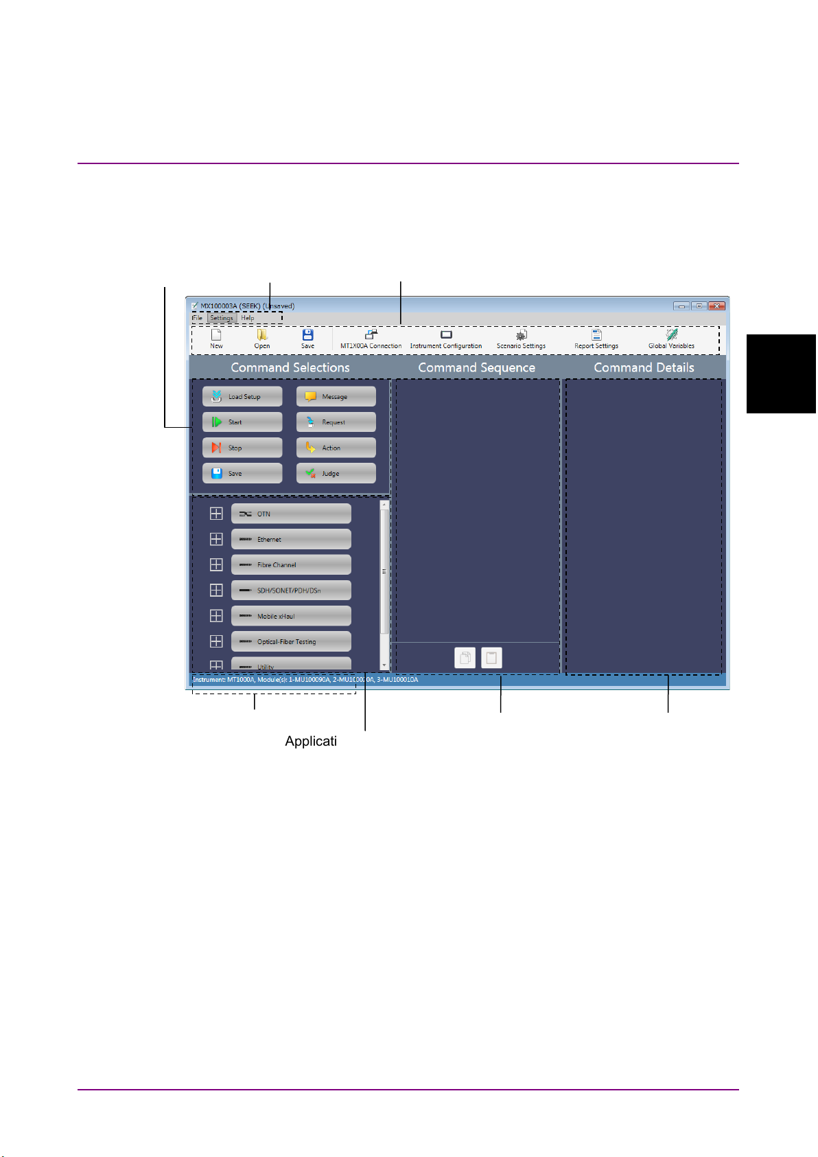
3.2 Explanation of the Window
Menu
Command Sequence
Command Details
Application Selections
Command
Selections
Instrument Configuration
Display
Toolbar
3.2.1 Window Configurations
3.2 Explanation of the Window
3
Figure 3.2.1-1 Window Components
Default language of MX100003A is English.
3-3
Page 26
File
New
Creates the new scenario.
Open
Loads the scenario from the file.
Save
Saves the scenario to the file.
Save As
–
Saves the scenario to a file as another file.
Save To
–
When the Network Master is connected via
of the Network Master.
Close
–
Exits MX100003A.
Settings
Select Platform
–
Selects a platform (MT1X00A or MT9083) on
which you want to run the scenario.
MT1x00A
Connection*
Checks the connection to the Network Master
which the IP address is specified.
Instrument
Configuration
Sets the configuration of the Network Master
and modules where the scenario will run.
Scenario Settings*
Sets the name and icon displayed on the
Network Master.
Report Settings*
Sets the Report file information used when the
report file is saved.
Global Variables*
Sets the variables used in the scenario. The
applications executed in the scenario.
Language
–
Changes the languages of the MX100003A.
Help
About
–
Displays the MX100003A information.
Chapter 3 Operation
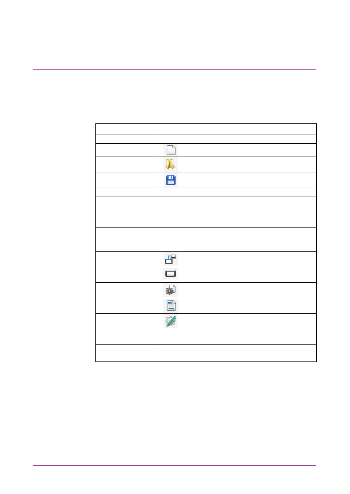
3.2.2 Menu
Menu configuration and icons displayed on the toolbar are shown
following table.
Table 3.2.2-1 Menu Configuration
Menu Icon Description
MT1X00A*
*: Not displayed when MT9083 is selected for Select Platform.
Note:
When loading a scenario file, the Network Master identifies the
string up to the period as the file name.
For example, the Network Master identifies all the following
scenario file names as “ETH_10G”. Therefore, only one of these
scenario files can be loaded to the Network Master.
ETH_10G.BERT.obcfg
ETH_10G.BERT.IPv4.obcfg
ETH_10G.RFC2544.obcfg
Ethernet, Saves the scenario in Internal folder
variables can be referred from multiple
3-4
Page 27
Operation
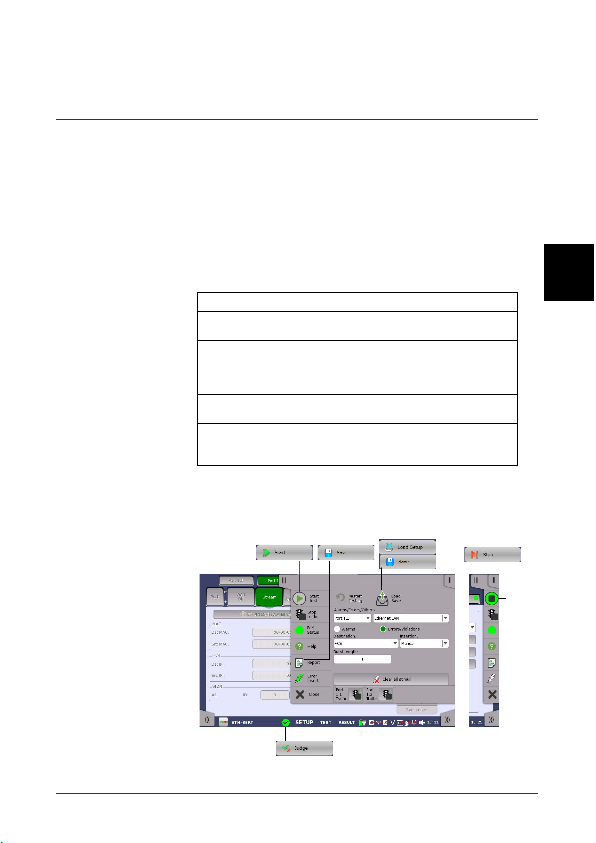
3.2.3 Toolbar
Load Setup
Loads a setup file (*.cfg) of the application.
Start
Starts measurements.
Stop
Stops measurements.
Save
Saves scenario logs to files.
be also saved.
Message
Displays a message.
Request
Displays a dialog box to enter a value.
Action
Performs the user defined action.
Judge
Judges the test result of the application.
If judged as “Fail”, the running scenario stops.
On the toolbar, icons of File menu items and Setting menu items are
placed. For the correspondence between the icon and the menu item, refer
to Table 3.2.2-1 “Menu Configuration”.
3.2.4 Command Selections
“Command” is the operation to the application. The following commands
are prepared in Command Selector.
3.2 Explanation of the Window
Table 3.2.4-1 Commands List
Command Description
Test results and Report file of the application can
The correspondence between icons on the Network Master screen and the
commands is shown in the following figure. There are no icons
corresponding to Message, Request, and Action.
3
Figure 3.2.4-1 Correspondence Between Network Master Icons and
Commands (Except Standard OTDR and VIP Applications)
3-5
Page 28
Chapter 3 Operation
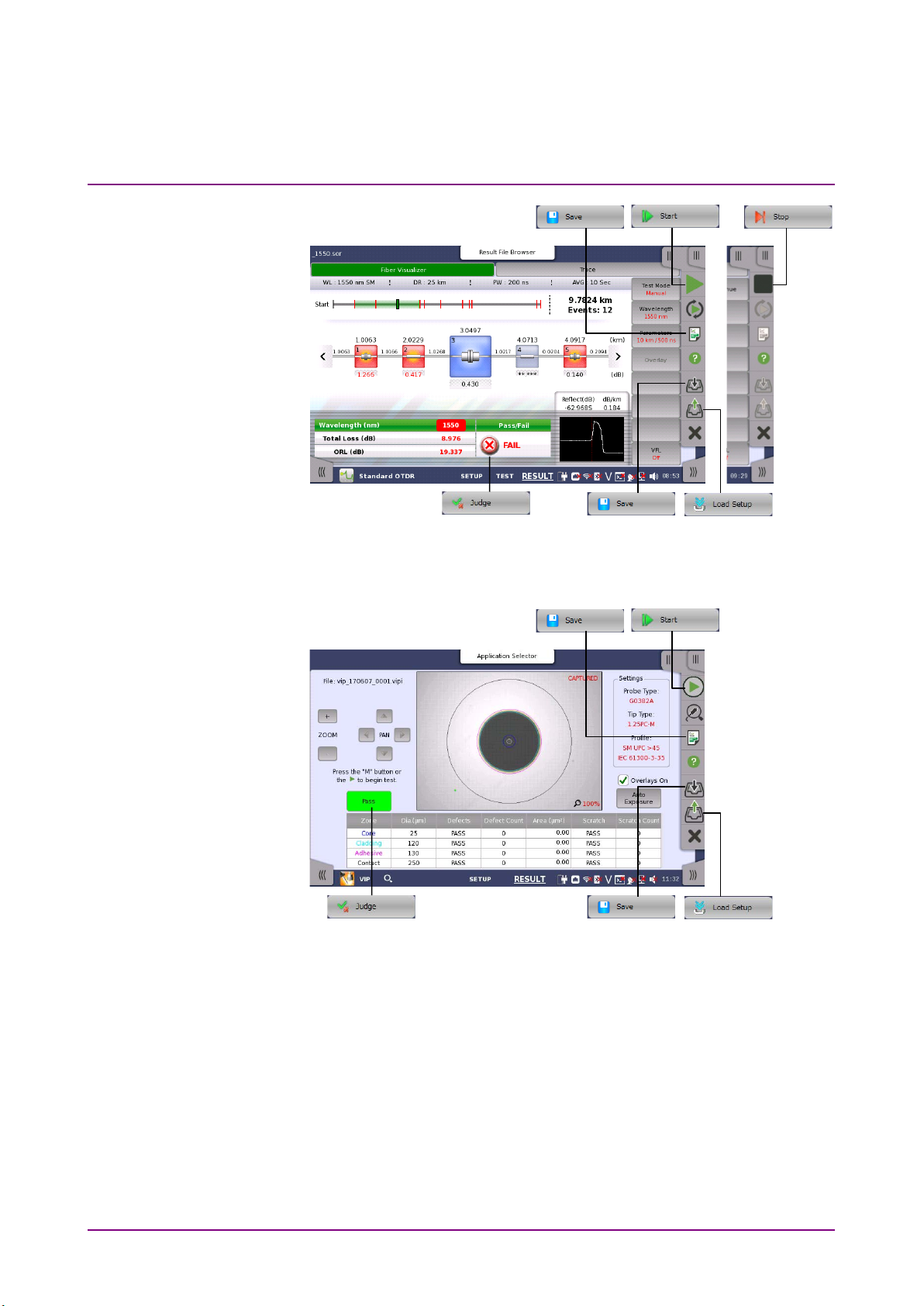
Figure 3.2.4-2 Correspondence Between Network Master Icons and
Commands (Standard OTDR Application)
3-6
Figure 3.2.4-3 Correspondence Between Network Master Icons and
Commands (VIP Application)
Page 29

Operation
3.2.5 Application Selections
In Application Selections, the lists of application are displayed.
You can open the list by operating as below to the button of OTN,
Ethernet, Fibre Channel, SDH/SONET/PDH/DSn, CPRI, Optical-Fiber
Testing, and Other.
● Click .
● Click the button and press the right arrow key of the keyboard.
● Double-click the button.
You can close the list by operating as below.
● Click .
● Click the button and press the left arrow key of the keyboard.
● Double-click the button.
3.2.6 Command Sequence
Edit the order of processing by placing commands and applications to this
area.
An application or a command can be placed by drag & drop operation.
The mouse icon changes to when an application or a command
cannot be placed.
You can open or close the list in Command Sequence in the same manner
described in Application Selections.
The copy button and the paste button are located under the area.
3.2 Explanation of the Window
3
: copies an application or a command.
: pastes the copied application or command.
3.2.7 Command Details
Clicking the command or the application placed in Command Sequence
displays the setting items on this area.
For contents of displayed items, refer to 3.4.5.2 “Copy and Paste” and
3.4.7 “Editing the Command”.
3-7
Page 30
Chapter 3 Operation
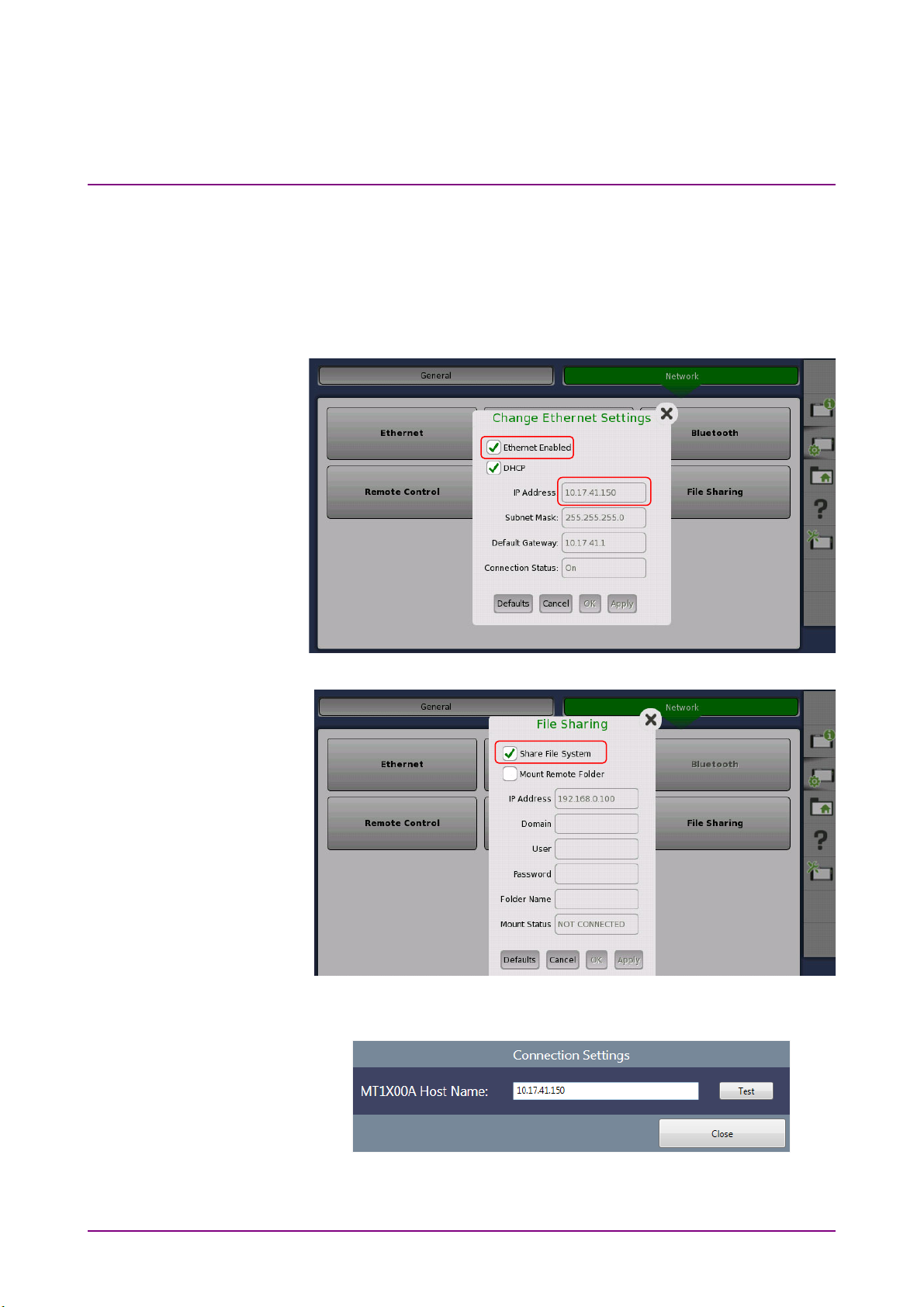
3.3 Connecting with the Network Master
MX100003A can access the folder of the Network Master by connecting to
the Network Master via Ethernet.
1. Select Ethernet Enabled on the Network Master, confirm the IP
address.
2. Select Share File System on the Network Master.
3. Connect Network Master and PC using the Ethernet cable.
4. Click MT1x00A Connection on MX100003A.
3-8
5. Enter the Network Master IP address confirmed in step 1 and click
Test . If MX100003A has connected to the Network Master, Success
message appears.
Page 31

3.4 Editing the Scenario
Click on toolbar to load the scenario file or click to start
editing new scenario.
3.4.1 Instrument Configuration
Set the hardware configuration of the scenario.
3.4 Editing the Scenario
When
MT1x00A
1. Click Instrument Configuration on the toolbar. The following dialog
box appears.
2. Select MT1000A, MT1040A, or MT1100A by pull-down menu on
Instrument. Available module(s) appear on Modules area.
3. Click the module button and drag it to Instrument.
To delete the module on Instrument, click on the button.
is selected for
Select Platform
3
Operation
4. Click OK.
3-9
Page 32

Chapter 3 Operation
5. If the current scenario is not saved, the message confirming the
edited scenario will be lost appears. Click
Instrument Configuration. Instrument Configuration is displayed at
left bottom of the window.
Yes if change the
When
MT9083/MT9085
1. Click
2. Select an MT9083/MT9085 option you want to use when running the
3. Click
Instrument Configuration on the toolbar. The following dialog
box appears.
scenario.
Close. Configuration is displayed at left bottom of the window.
is selected for
Select Platform
3-10
Page 33

Operation
3.4.2 Scenario Settings
Set the scenario information to display on the Network Master screen.
3.4 Editing the Scenario
1. Click
2. Enter the scenario name up to 12 characters in alphabetic-numeric.
3. Click
4. Enter the comment.
5. Select the Password check box if requiring the password when
Scenario Settings on the toolbar. The following dialog box
appears.
You cannot set Scenario Name as blank.
Browse. Specify the image file displaying as the icon by the
dialog box.
running the scenario. Enter a 4 to 8-digit password.
3
6. To upload a scenario result file to the storage service or user-specified
HTTP server via the cloud server, select the
Select the upload destination.
Storage Service: Commercially available storage service
User-specified HTTP server: Server specified by URI and other
information in the scenario
Select the file(s) to upload.
Scenario Result Directory: All output files
Scenario Result Reports: Report file only
7. Click
Notes:
Close.
● An MX109020A Site Over Remote Access Basic License
agreement is required to upload the result files to the storage
service or user-specified HTTP server via the cloud server.
● Upload of the result files is carried out by the MT1000A
Network Master Pro and MT1040A Network Master Pro.
Upload check box.
3-11
Page 34

Chapter 3 Operation
Example of Scenario Settings and Displays on the Network Master are
shown below.
Figure 3.4.2-1 Example of Scenario Settings
Figure 3.4.2-2 Display Example on Network Master
(Scenario Manager)
Figure 3.4.2-3 Display Example on Network Master (Utilities)
3-12
Page 35

Operation
3.4.3 Report Settings
Customer
REPORT_SETTING_CUSTOMER
Project
REPORT_SETTING_PROJECT
Operator
REPORT_SETTING_OPERATOR
Notes
REPORT_SETTING_NOTES
Set the Report file header information of the application.
3.4 Editing the Scenario
1. Click
2. Select
3. Enter
Report Settings on the toolbar. The following dialog box
appears.
Select Format check box(es) to specify the report file format.
Customer, Project, Operator and Notes.
If
Use Global Variable check box has selected, the variable name
appears in Global Variables dialog box and the variable value cannot
be set in Report Settings dialog box.
Table 3.4.3-1 Variable Names of Report Settings
3
Items in Report
Settings
4. To include a logo in Report, select Include Logo check box and click
Browse. Specify the image file of the log using the dialog box.
5. To include the Performance Verification Dates in Report, select
Include check box.
6. Click
The report file in PDF format will be saved in the designated folder after
running the scenario.
Close.
Global Variable Name
Figure 3.4.3-1 Report File Header Example
3-13
Page 36

Chapter 3 Operation
3.4.4 Global Variables
Define the variables used in the scenario. The variables defined in this
dialog box can be referred from multiple applications executed in the
scenario. Also, they can be edited on the Network Master screen. For the
operation of the Network Master, refer to 4.2.3 “Editing the Scenario”.
1. Click
Global Variables on the toolbar. The following dialog box
appears.
2. To add a variable, click .
To change the order, click or .Clicking deletes the
variable.
3-14
Page 37

3.4 Editing the Scenario
Operation
MAC
A hexadecimal number in MAC address format.
IPV4
A decimal number in IPv4 address format.
IPV6
A hexadecimal number in IPv6 address format.
STRING
A string.
VALUE
A numeric value. Following can be set.
Decimals: Number of digits under the decimal point
LIST_STR
Enter string for appending the list item. Numeric value is
processed as string.
3. Select Type from the following.
Table 3.4.4-1 Type of Global Variables
Type Description
Format: BIN (Binary), NUM (Decimal), HEX (Hexadecimal)
Min: Minimum value
Max: Maximum value
4. Enter the variable name in Name column.
5. Enter description of the variable in Comment column.
3
6. Enter default value of the variable in Value column.
7. When Type is set to VALUE or LIST_STR, click to open
Variable Editor dialog box.
8. When Type is set to
When Type is set to LIST_STR, enter the string in
click . You can change order by clicking the item in
click or . To delete a list item, click the item in
click .
VAL UE , enter Format, Min, Max and Decimals.
New Selection and
Selection and
Global
Selection and
9. Click
Close or .
3-15
Page 38

Inner application
Outer application
Chapter 3 Operation
3.4.5 Editing the Sequence
3.4.5.1 Placing Applications and Commands
Edit the sequence by dragging an application or a command to this area.
There are two positions they can be placed:
Outer application and Inner application.
Figure 3.4.5-1 Positions to Place Applications and Commands
Place applications at Outer application. Place commands excluding
Request at Inner application.
Only Request can be placed at both positions.
When Request is placed at Outer application, the inputted variable can be
referred from the applications executed subsequently.
When Request is placed at Inner application, the inputted variable can be
referred from the only applications executing.
3-16
Page 39

3.4 Editing the Scenario
Operation
Figure 3.4.5-2 Position to Place Applications
Place commands at Inner application. Gray line appears if placing a
command to Command Sequence area.
Command will be placed if dropping the command when length of the
gray line is the same as application button width.
3
Figure 3.4.5-3 Position to Place Commands
Gray rectangle appears if dragging a command to the application button
in the Command Sequence area. Dropping the command in this case will
append to the last position of the application.
3-17
Page 40

Chapter 3 Operation
Figure 3.4.5-4 Appending a Command at Last Position of the
Application
Note:
The command once placed in the application cannot be moved to
other application. In the example of Figure 3.4.5-4, you cannot
move Start command in OTN BERT to OTN RTD.
To delete the placed command:
● Click the application or command and press
the keyboard.
● Click on the application or command. Click on the displayed
message.
Notes:
● If deleting the application or command, you can not restore it.
● If the application is deleted, all the commands placed in the
application will be deleted.
The custom application of Other can write the whole process from
starting to quitting the application in the SCPI command. Thus, the
custom application can place only the following commands.
Message, Request, Action, Judge
Delete
Back Space
or
of
3-18
Page 41

Operation
3.4.5.2 Copy and Paste
3.4 Editing the Scenario
You can copy and paste an application or a command in the sequence.
You cannot cancel (Undo) or repeat (Redo) the operation.
Copying and Pasting an Application
1. Place applications and commands in the area.
2. Click the desired application (in the example,
3. Click the copy button.
4. Click the application (in the example,
paste the copied application.
5. Click the paste button. The copied application is inserted under the
application selected at step 4.
If clicking the paste button without selecting the application, the copied
application is inserted at the end of the sequence.
OTN APS) where you want to
OTN RTD).
3
Figure 3.4.5.2-1 Copying and Pasting an Application
When a command has been clicked after copying an application, the paste
button will be disabled. Right-clicking the selected command enables the
paste button.
Copying and Pasting a Command
1. Place applications and commands in the area.
2. Click the desired command (in the example,
3. Click the copy button.
4. Click the command (in the example,
want to paste the copied application.
5. Click the paste button. The copied command is inserted under the
command selected at step 4.
Stop in OTN APS) where you
Message in OTN RTD).
3-19
Page 42

Chapter 3 Operation
If clicking the paste button after selecting the application, the copied
command is inserted at the end of the sequence of the application.
Figure 3.4.5.2-2 Copying and Pasting a Command
The following restrictions apply to copying a command.
● Only one Load Setup command can be placed in the application
sequence. Therefore, multiple Load Setup commands cannot be pasted
into the same application.
● Some commands cannot be pasted between Optical Fiber Testing
application and other applications.
3-20
Page 43

Operation
3.4.6 Editing the Application
Clicking the application placed in the Command Sequence allows to select
the port(s) to use in the Command Detail area.
Launch with + OTN:
Displayed for the application to which OTN layer can be added, select
whether adding OTN layer or not.
3.4 Editing the Scenario
3
Figure 3.4.6-1 Application Details
3-21
Page 44

Chapter 3 Operation
3.4.7 Editing the Command
Clicking the command placed in the Command Sequence allows to edit
the parameter(s) in the Command Detail area.
3.4.7.1 Load Setup
Set the setup filename (*.cfg) of the application to load.
Figure 3.4.7.1-1 Load Setup Details
Figure 3.4.7.1-2 Load Setup Details (For Standard OTDR)
Figure 3.4.7.1-3 Load Setup Details (For OLTS)
Figure 3.4.7.1-4 Load Setup Details (For VIP)
3-22
Select File
Load the application settings from the configuration file. The name of the
loaded configuration file is displayed in the
To select the file saved in the PC, click
File Name field.
Browse PC.
Page 45

3.4 Editing the Scenario
Operation
To select the file saved in the folder of Network Master, click Browse
MT1X00A.
Create File
For the Standard OTDR application, OLTS application, and the VIP
application,
This allows you to newly create a configuration file or edit an existing
configuration file. The edited results are saved to the scenario file
(*.obcfg), and the configuration file (*.cfg) is not changed.
Create File is displayed.
Note:
If the scenario file name includes a period, the Network Master
identifies the string up to the period as the file name. Refer to Note
in 3.2.2, “Menu”.
New: Newly creates a configuration file, discarding any changes you
have made.
Edit: Allows you to edit the current settings.
Clicking
New or Edit opens the following dialog box.
3
Figure 3.4.7.1-5 OTDR CFG File Editor (For MU100021A)
3-23
Page 46

Chapter 3 Operation
Figure 3.4.7.1-6 OLTS CFG File Editor
Figure 3.4.7.1-7 VIP CFG File Editor
For descriptions of the setting items, refer to the
MT1000A Network
Master Pro OTDR Modules Operation Manual (M-W3810AE)
.
3-24
Page 47

Operation
3.4.7.2 Start
3.4 Editing the Scenario
Set how to start the test. Selectable options vary according to the
application. The parameters for some applications cannot be edited.
3
Figure 3.4.7.2-1 Start Details
Auto: Starts the test immediately and stops the test automatically
when the measurement completes.
Timed: Starts the test immediately and stops the test when the
specified time has elapsed.
Manual: Starts the test if or on the Network Master has
touched.
3.4.7.3 Stop
There are no parameters to set for the Stop command.
Note:
Stop command cannot be placed in the VIP application.
3-25
Page 48

Chapter 3 Operation
3.4.7.4 Save
Set the filename to save. The file is saved in the Internal/Scenario_logs
folder of Network Master.
Note:
Save command cannot be placed in the Discovery application.
Figure 3.4.7.4-1 Save Details
Append Timestamp: Appends data and time to the filename.
Generate Report: Generates the Report file and saves.
When %1 is entered in
defined in 3.4.4 “Global Variables” can be selected. The string selected for
Select Variable will be the file name automatically.
File Name, Select Variable appears. The variables
Figure 3.4.7.4-2 Select Variable
3-26
Page 49

Operation
3.4.7.5 Message
3.4 Editing the Scenario
Set the title, text, and image displayed in the message.
3
Figure 3.4.7.5-1 Example of Message Settings
To delete the image, click .
The following message appears if the scenario has run on the Network
Master.
Figure 3.4.7.5-2 Example of Displayed Message
3-27
Page 50

Chapter 3 Operation
3.4.7.6 Request
Drop Request command in the Command Sequence area to display a
variable name on the button. Define parameters to input for Request
command. For setting items, refer to 3.4.4 “Global Variables”.
When Request is placed at Inner application, the input variable can be
referred only from the running applications.
When Request is placed at Outer application, the input variable can be
referred from multiple applications.
Figure 3.4.7.6-1 Example of Request Settings
In this settings, the following dialog box is displayed on the Network
Master.
Figure 3.4.7.6-2 Example of Displayed Dialog Box
Selecting LIST_STR for
the dialog box.
Type allows users to edit selections to display in
3-28
Page 51

3.4 Editing the Scenario
Operation
Three or more selections
Two selections.
3
Figure 3.4.7.6-3 Setting Example and Dialog Boxes When Type is
LIST_STR
When there are two selections, two buttons are displayed in the dialog box.
Touching one of them closes the dialog box. When there are three or more
selections, a combo box is displayed in the dialog box. Touching
the dialog box.
OK closes
3-29
Page 52

Dialog box displayed when
Dialog box when it has ten or
Chapter 3 Operation
Selecting the Use Action Buttons check box enables to edit the Action
buttons. The dialog box displayed on Network Master is closed by
touching one of the Action buttons at the bottom.
this scenario is executed
more selections
Figure 3.4.7.6-4 Setting Example and Dialog Boxes When Using Action
Buttons
Note:
The Action buttons can be set up to three.
3-30
Page 53

Operation
3.4.7.7 Action
3.4 Editing the Scenario
Set the action against the application.
When a comment is entered, a maximum of 10 characters are displayed
on the button. When left empty,
Set Source MAC: Sets the Source MAC address.
Set Destination MAC: Sets the Destination MAC address.
Set Source IPv4: Sets the Source IPv4 address.
Set Destination IPv4: Sets the Destination IPv4 address.
Custom: Performs the user defined action. Refer to “In
case of Custom” on next page.
“Set Source MAC” to “Set Destination IPv4” appear on the specific
Ethernet applications.
Action is displayed instead.
3
Figure 3.4.7.7-1 Action Details
In case of other than Custom
The SCPI command is displayed in SCPI field.
1. Specify Port and Stream numbers.
2. Select a variable of the address at
If no variables are on the list, define the variable by using
Variable or Request command.
Note:
The default timeout value of SCPI command is 30 seconds.
When sending the command which takes more than 30 seconds to
receive the response, select
timeout value by using TIMEOUT command.
Example of script:
TIMEOUT, 60000
EQUAL, "SYST:WAIT:DUR 30"
EQUAL,,"*OPC?
"
Select Variable.
Global
Custom and then select Script. Change
3-31
Page 54

Chapter 3 Operation
In case of Custom
There are two ways to define the action.
Script: Runs the script written with commands described in Appendix B
“Command Reference”.
SCPI: Sends a SCPI command written in
MT1000A Network Master
Pro MT1100A Network Master Flex Remote Scripting Operation
Manual (M-W3736AE)
Scripting Operation Manual (M-W4041AE)
,
MT1000A/MT1100A/MT1040A Remote
, and
MT1000A
Network Master Pro OTDR Modules Remote Scripting
Operation Manual
Select Script or SCPI.
If selecting SCPI, enter the SCPI command in the SCPI field. If a query
command is entered, “FAIL” is returned.
(M-W3859AE)
to the Network Master.
Figure 3.4.7.7-2 Action Details (SCPI)
Entering % and a number as a parameter displays
Select a variable from defined name in 3.4.4 “Global Variables” or
3.4.7.6 ”Request”.
Figure 3.4.7.7-3 Select Variable of SCPI
Select Variable.
3-32
Page 55

3.4 Editing the Scenario
Operation
3
Figure 3.4.7.7-4 Action Details (Script)
If selecting
To load the script from the file, click
To check the script syntax, click
to Appendix C “Error Messages”.
Script, write the script into the field.
Import from file.
Validate. For messages of the result, refer
3.4.7.8 Judge
Set the method to judge Pass/Fail of the test result.
Summary: Uses the judgement displayed in the status area.
Custom: The method specified by the script or the SCPI command
Note:
If judged as “Fail” by the Judge command, the running scenario
stops.
If selecting
If selecting
If selecting
To load the script from the file, click
To check the script syntax, click
to Appendix C “Error Messages”.
Custom, select Script or SCPI.
SCPI, enter the SCPI command in the SCPI field.
Script, write the script into the field.
Import from file.
Validate. For messages of the result, refer
3-33
Page 56

Chapter 3 Operation
Figure 3.4.7.8-1 Judge Details (Summary)
3-34
Figure 3.4.7.8-2 Judge Details (Script)
Figure 3.4.7.8-3 Judge Details (SCPI)
Note:
The default timeout of a SCPI command is 30 seconds. To send a
SCPI command that takes more than 30 seconds to receive the
response, write the SCPI command in the script.
Page 57

Operation
3.4.8 Editing Scenario Settings for MT9083/MT9085
To edit MT9083 Series ACCESS Master settings, click the Settings menu,
click
Select Platform, and then select MT9083/MT9085.
For descriptions of the setting items, refer to the
Master Operation Manual (M-W3634AE)
Master Operation Manual (M-W3971AE)
or
.
3.4 Editing the Scenario
MT9083 Series ACCESS
MT9085 Series ACCESS
3
Figure 3.4.8-1 Appearance of the Window When MT9083/MT9085 is
Selected for Select Platform
Edited settings are saved as a scenario file (*.acm) for the ACCESS
Master. By running a scenario file in Scenario Manager Lite on the
ACCESS Master, the ACCESS Master performs Standard OTDR
measurement according to the edited settings. Measurement results are
saved to a file named as specified in the
Result File Name field.
3-35
Page 58

Chapter 3 Operation
3.5 Checking the Scenario Contents
Scenario contents are checked when you try to save the scenario.
Clicking
has error(s).
Correct the error displayed on the message. The scenario cannot be saved
until no more error is detected.
Save on the toolbar displays the error message if the scenario
Figure 3.5-1 Error Message Example
3-36.
Page 59

Running the Scenario
Chapter 4 Running the Scenario
This chapter explains how to run the scenario created by MX100003A on
the Network Master.
For how to run scenarios on the MT9083 Series ACCESS Master, refer to
Chapter 16 “Scenario Manager Lite” in the
Master Operation Manual (M-W3634AE)
For how to run scenarios on the MT9085 Series ACCESS Master, refer to
Chapter 14 “Scenario Manager Lite” in the
Master Operation Manual (M-W3971AE)
4.1
Copying the Scenario Files ........................................... 4-2
4.2 Registering and Running the Scenario ......................... 4-3
4.2.1 Registering the Scenario .................................. 4-3
4.2.2 Running the Scenario ....................................... 4-4
4.2.3 Editing the Scenario ......................................... 4-7
4.2.4 Saving the Scenario ......................................... 4-8
4.3 Result Files ................................................................... 4-9
MT9083 Series ACCESS
.
MT9085 Series ACCESS
.
4
4-1
Page 60

Chapter 4 Running the Scenario
4.1 Copying the Scenario Files
Copy the scenario file(s) created by MX100003A to the storage in the
Network Master.
Using USB flash drive
1. Connect a USB flash drive to the PC.
2. Copy the scenario file(s) to the USB flash drive.
3. Unplug the USB flash drive from the PC and connect it to the
Network Master.
4. Tou ch
5. Tou ch
6. Touch
7. Tou ch
Saving via Ethernet
1. Click
connected to the Network Master via Ethernet.
on the Instrument Toolbar of the Network Master.
Usb folder and touch the scenario file name.
COPY .
Internal folder, and touch PASTE .
File, Save To MT1X00A in the menu when MX100003A is
4-2
2. Enter the file name and click
Save.
Page 61

4.2 Registering and Running the Scenario
Running the Scenario
4.2 Registering and Running the Scenario
To run the scenario, Register the scenario using Scenario Manager.
4.2.1 Registering the Scenario
1. Display the Utilities screen of the Network Master.
2. Touch
3. Touch
4. Select a scenario file and touch
been loaded, the content of the scenario is displayed in the list of
Scenario Manager.
5. Touch
Scenario Mgr.
.
Import. When the scenario file has
. Confirm that the icon of the loaded scenario appears in
the Utilities screen.
4
Touching
icon on the Utilities screen to invisible.
Hide on the setup screen of Scenario Manager sets the scenario
4-3
Page 62

Chapter 4 Running the Scenario
4.2.2 Running the Scenario
1. Touch the scenario icon you have registered on the Utilities screen of
the Network Master. The destination folder of the result files of
scenario appears at
touch the field and enter the folder name.
File will be saved in the following folder:
Internal/Scenario_logs/(scenario name)/(string in the field_date and
time_Pass/Fail)
Example:
Internal/Scenario_logs/mt100a_sample-2/2016-03-14@10-28-35_Fail
Result folder. If you wish to create the sub-folder,
The destination drive of the result folder can be set when touching
an icon on Utilities screen after USB flash drive was connected to
the Network Master.
Even if
Internal memory temporary and moved to USB flash drive after the
scenario execution has finished.
In cases below, the warning message appears when Network Master
has tried to save result files to USB flash drive. If Network Master
failed to save result files to USB flash drive, they are stored in
Internal memory
●
●
2. Select the check box for the application you want to run.
Result Folder :Usb has been set, result files are stored in
USB flash drive had been removed before the scenario execution
finished.
The free space of the USB flash drive is shortage.
4-4
3. Touching
starts running the scenario.
Page 63

4.2 Registering and Running the Scenario
Running the Scenario
4. Depending on the scenario contents, the panel operation (entering
the variable etc.) is required.
The scenario stops when the each progress of all applications has
changed to PASS or FAIL.
4
If the VIP scenario has started, the VIP screen appears. In this case,
Report, File Save, and File Load icons on Application Toolbar are
disabled.
Perform the following operation to close the VIP screen and return to the
scenario screen.
●
Save the results by touching
●
Quit the measurement by touching
Yes on the above screen.
.
4-5
Page 64

Chapter 4 Running the Scenario
4-6
Page 65

Running the Scenario
4.2.3 Editing the Scenario
The warning icon appears at right of Resource Assignment
case, touch the Value field and set the available port(s).
The Scenario Manager of the Network Master can edit the following
items:
●
Port(s) occupied by the application
●
Global variables
1. Display the Utilities screen of the Network Master.
4.2 Registering and Running the Scenario
2. Touch
3. Touch the scenario icon to edit.
4. Touch
Scenario Mgr.
Edit or right-bottom tab .
4
5. To edit the port(s) the application occupies, touch the field in Val ue
column of Resource Assignment.
6. To edit the variables, touch the field in Valu e column of Variables.
7. To back to Setup screen, touch the right-bottom tab
when the port defined in the scenario does not exist. In this
.
4-7
Page 66

Chapter 4 Running the Scenario
4.2.4 Saving the Scenario
The Scenario can be saved in the following procedure:
1. Display the Utilities screen of the Network Master.
2. Touch
3. Touch the scenario icon to save.
4. Touch
5. Enter the file name and touch
Scenario Mgr.
Export.
Export.
4-8
Page 67

Running the Scenario
4.3 Result Files
4.3 Result Files
The result files of the scenario will be saved in the Internal/Scenario_logs
folder of the Network Master.
The folder which has the same name as the scenario file will be created,
sub-folder will be created according to the time scenario started.
Note:
If the scenario file name includes a period, the Network Master
identifies the string up to the period as the file name.
For example, the Network Master identifies all the following
scenario file names as “ETH_10G”. Therefore, the folders created
for these scenario files will be all given the same name “ETH_10G”.
ETH_10G.BERT.obcfg
ETH_10G.BERT.IPv4.obcfg
ETH_10G.RFC2544.obcfg
4
Figure 4.3-1 Result Files and Destination Folder
The following result files will be saved.
CommandLog.txt
The communication log between the Network Master and the scenario.
The communication time, SCPI commands, and responses are
recorded.
SequenceLog.txt
The log of the messages which were displayed on the Network Master
screen.
To see the contents of the file, select the file and touch
VIEW FILE .
4-9
Page 68

Chapter 4 Running the Scenario
Note:
VIEW FILE cannot display two-byte characters correctly. When
two-byte characters are included in the result files, copy the result
files to PC to confirm the contents.
4-10.
Page 69

Appendix A
Appendix A Syntax of Script
This section explains the syntax of script.
A.1
Elements of the Script ................................................... A-2
A.2 Line ............................................................................... A-3
A.3 Column .......................................................................... A-4
A.3.1 String Column ................................................... A-4
A.3.2 Numeric Column ............................................... A-8
A.3.3 Operator Column .............................................. A-9
A.3.4 Variable Column ............................................... A-9
A.3.5 Label Column ................................................... A-9
A-1
Page 70

Line
Comment Line
Label Line
Command Line
Command Column
Parameter Column
Numeric Column
String Column
Operator Column
Label Column
Variable Column
Comment Line
Label Line
Command Line
Parameter Column
Command Column
Variable Column
Operator Column
Numeric Column
String Column
Label Column
Appendix A Syntax of Script
A.1 Elements of the Script
Script used in Action command and Judge command of the scenario is
written in text format. The character code of script is UTF-8. To load the
script created or edited by using general purpose text editor to
MX100003A, be sure to save text file in UTF-8 code.
Elements of script are shown in the figure below.
Figure A.1-1 Elements of the Script
Correspondence between example script and elements is shown in the
figure below.
A-2
Figure A.1-2 Example Script
Page 71

Appendix A
A.2 Line
A.2 Line
The script syntax consists of one line. The comment, label, or command
should be written in one line.
Lines are separated by line feed characters.
The blank line and the line which contains space only are ignored when
running the script.
The line can be distinguished to three types in the following depending on
the first character.
Comment Line
The first character of Comment line is single quotation (‘).
Alphanumeric characters, symbols, two-byte letters are allowed to use in
the comment line.
Example:
‘Script of Ping test to DNS server
Label Line
The first character of Label line is colon (:).
Label line is used as the target to jump the process.
Label line is used for the target when jumping the process during running
the script.
Alphanumeric characters and under bar (_) are allowed to use in the label
name.
Example:
:Setup_BERT1
Command Line
Command lines are lines other than comment and label lines.
Command line is consisted of columns which are separated by comma.
The command listed in Appendix B should be written in the first column
of the command line.
There are two kinds to Command lines depending on the command used.
●
Command line performing the judgement
Judges pass or fail of the application test result when processing the
command line.
Scenario execution stops when being judged as Fail.
●
Command line without performing judgement
Does not judge the application test results when the command line has
processed.
A-3
Page 72

Appendix A Syntax of Script
A.3 Column
The part between commas in the command line is called “Column”. The
comma at end of the line may be omitted.
The space and tab contained in the column are ignored. However they are
not ignored if they are part of string enclosed double quotation (“ ”).
There are the following kinds of columns used in the command line.
Command Column
The first column of the command line. Write the command listed in
Appendix B.
Example:
COPY,CALC,IF, THEN,ELSE,ENDIF,
GOTO,GOSUB,RETURN,END
Parameter Column
The second or later column of the command line. Write the parameter(s)
of command line.
A.3.1 String Column
In String Column, write the string parameter for the command.
String constant, variable, or both of them are allowed to write in the
String Column. Connecting the strings in the String Column is also
allowed.
String Constant
String constant is described by string enclosed with double quotation (").
Example:
"*CLS"
"*ESR?"
“\” can be used as the escape character. For example, “\n” starts a new
line.
The following is the example describing the string double quotations are
contained.
Example:
"XXXX:YYY \"abcd\"\n Second Line"
is regarded as
XXXX:YYY "abcd"
Second Line
A-4
Page 73

A.3 Column
Appendix A
String Variable
Variable can be used in the String Column.
The variable is indicated by appending “%” at top of the variable name.
The character in the variable name is case sensitive. For example, %Port
and %port are not the same variables.
Alphanumeric characters and under bar (_) are allowed to use in the
variable name.
Example:
%String,
%Counter_Value,
The variables does not have types such as integer or string. The variable
can store a numeric value and a string.
The statement of the variable is not required. A variable discovered for
the first time during the script execution will be initialized immediately.
The default setting of string is "". If the variable is initialized once, the
memory area for the variable is reserved until the script execution ends.
For the variable in the String Column, even if the numeric value is stored
in the variable, it is converted to the string and processed.
The converting format from numeric value to string can be specified by
using colon. Number of significant figures can be also specified.
%variable namd:degit number.degit number under decimal point
Example:
%Value:6.3
When converting the contents of variables from a numerical value to a
string and outputting it, the number of valid digits can be specified.
This setting is compliant to specifying real number (same as printf
function of C language).
If string is stored in the variable, the specified format is ignored.
The following names are reserved for string variable name.
A-5
Page 74

%NM_JUDGE_RESULT
Result of Judge command (Summary) *1
%RESULT_FOLDER
File path and folder name which the result file
are saved. *1
%RESULT_FOLDER_BASE
Basic part of the folder name which the result
name are not included.
%REPORT_SETTING_COMBINE
Setting output of multiple reports.*
application.
%REPORT_SETTING_CUSTOMER
Customer information in Report Settings*3,*4
%REPORT_SETTING_PROJECT
Project name in Report Settings*3,*4
%REPORT_SETTING_OPERATOR
Operator name in Report Settings*3,*4
%REPORT_SETTING_NOTE
Notes in Report Settings*3,*
report.
%SUMMARY_REPORT_FILE_NAME
Portion of the report file name*4
%SUMMARY_REPORT_FILE_NAME_
HEADER
Header of the report file name*4
%TEST_REPORT_SETTING_NOTES
Notes to be output to the test report *4,*5
%HTTP_UPLOAD_CUSTOM_HEADER1
HTTP header to be inserted in HTTP request*6
%HTTP_UPLOAD_CUSTOM_HEADER2
HTTP header to be inserted in HTTP request*6
%HTTP_UPLOAD_CUSTOM_HEADER3
HTTP header to be inserted in HTTP request*6
%HTTP_UPLOAD_CUSTOM_HEADER4
HTTP header to be inserted in HTTP request*6
%HTTP_UPLOAD_CUSTOM_HEADER5
HTTP header to be inserted in HTTP request*6
Appendix A Syntax of Script
Table A.3.1-1 Reserved Variable Name
Variable Name Description
file are saved. *1
Date, time, and pass/fail result of the folder
If set to 0, a report is created for each
4
When nothing has not been set
%TEST_REPORT_SETTING_NOTES
to
parameter value will be output to the test
2
, this
*1: Do not set a value to these variables.
*2: Available when the module is MU100020A, MU100021A,
*3: Applied to reports for all application. When
*4: These variables are available for the Network Master which software
*5: This variable is applied to only application which the variable value
*6: When sending a result file from the Network Master to the
A-6
MU100022A, or MU100023A.
Use Global Variable is
selected in 3.4.3 “Report Settings”, the variable is displayed in Global
Variable dialog box.
version is 8.01 or later. If Network Master’s version is 8.00 or earlier,
values set in 3.4.3 “Report Settings” are output to the report file.
has been set.
user-specified HTTP server via the cloud server, up to five headers
can be inserted in HTTP request.
Page 75

A.3 Column
Appendix A
In case of Figure A.3.1-1, the value stored in the variable are shown
bel o w.
%RESULT_FOLDER_BASE
%RESULT_FOLDER
Internal/Scenario_logs/sample-scenario1/ABCD_2016-03-16@18-01-15_Fail
Figure A.3.1-1 Example of Result Folder Setting
To use the variables defined in 3.4.4 “Global Variable” and 3.4.7.6
“Request”, append the “%” before the variable name. In case of the setting
example in Figure A.3.1-2, the variable name will be “%Site_A” in the
script for using “Site_A”.
ABCD
Figure A.3.1-2 Example of Global Variable Setting
If the scenario execution has completed, the following PDF file will be
created.
Summary_***.pdf
Using
portion.
Example:
COPY, %SUMMARY_REPORT_FILE_NAME, "Anritsu"
(The name of a created file will be Summary_Anritsu.pdf.)
String Concatenation
Concatenation of string constant, variable, or both of them in String
Column is available.
Constants and variables written straight in the column are regarded as a
concatenated string.
Example:
"*C" "LS",
(Constants are concatenated and treated as “*CLS”)
"MKP_CDP" %A,
(When the value of variable %A is 10, the concatenated string will be
“MKP_CDP 10”)
%SUMMARY_REPORT_FILE_NAME
enables to set a name to the ***
A-7
Page 76

Appendix A Syntax of Script
A.3.2 Numeric Column
In Numeric Column, write the numeric parameter for the command.
Numeric constant or variable are allowed to write in the Numeric Column.
It is allowed to write only one value in a column. Calculation in Numeric
Column is not available.
The range of the numeric constant and variable are shown be low.
For integer: –2147483648 to 2147483647
For decimal: Up to 15 digits under the decimal point
Numeric Constant
Numeric value can be written in real number. Digits under the decimal
point can be omitted.
Negative value is described by using minus sign at top of digits. If value is
less than 1, do not omit a zero (0) before decimal point.
Write (0.25), not .25
Writing 0.25 is correct, but .25 is not correct.
Example:
10
-30.0
Numeric Variable
Variable can be used in the Numeric Column.
The variable is indicated by appending “%” at top of the variable name.
The character in the variable name is case sensitive. For example, %Port
and %port are not same variable.
Alphanumeric characters and under bar (_) are allowed to use in the
variable name.
Example:
%String,
%Counter_Value,
The statement of the variable is not required. A variable discovered for
the first time during the script execution will be initialized immediately.
The default setting of string is 0. If the variable is initialized once, the
memory area for the variable is reserved until the script execution ends.
For the variable in the Numeric Column, even if the string is stored in the
variable, it is converted to the numeric value automatically at processing
the variable. The value is set to 0 for the string which is not able to
convert to numeric value.
To use the variables defined in 3.4.4 “Global Variable” and 3.4.7.6
“Request”, append the “%” before the variable name. In case of the setting
example in Figure A.3.1-2, the variable name will be “%max_delay_ms” in
the script for using “max_delay_ms”.
A-8
Page 77

Appendix A
A.3.3 Operator Column
+
Adding
!=
Not equal
–
Subtraction
<
Greater
*
Multiplication
>
Lesser
/
Division
<=
Equal or greater
&
Bitwise AND
>=
Equal or lesser
|
Bitwise OR
&&
Logical AND
==
Equal
||
Logical OR
TEST_START_APP
Top position of command sequence
in the application
The column which one of operator in the following table is written.
A.3.4 Variable Column
Variable Column is used to store a value from the command output.
Usually the processed value or the calculated value is stored to a variable.
Only one variable can be written in the Variable Column.
Writing a numeric constant, a string constant, or an operator etc. occurs
the error. Calculation in Variable Column is not available.
Example:
%Calc_Value,
A.3 Column
Table A.3.3-1 Operator List
Operator Process Operator Process
A.3.5 Label Column
The column which the string of Label line is written. This column is used
to write the label of jump target in GOTO command or GOSUB command.
Example:
GOTO, :Label
The following label name is reserved.
Table A.3.5-1 Reserved Label Name
Label Name Description
A-9
Page 78

Appendix A Syntax of Script
A-10.
Page 79

Appendix B
Appendix B Command Reference
This section explains the function, parameter, and example of the
commands.
B.1
Command Description Method ..................................... B-2
B.2 Command List ............................................................... B-3
B.3 Commands not Performing the Judgement .................. B-5
B.4 Commands Performing the Judgement ...................... B-30
B-1
Page 80

<>
The string enclosed by angle bracket is a parameter name.
[]
The parameter enclosed by square bracket can be omitted.
<result>
Variable Column
Variable used to store the
calculation result
<value1>
Numeric/String Column
Value for calculation
<operator>
Operator Column
Operator describing the
calculation type
<value2>
Numeric/String Column
Value for calculation
Appendix B Command Reference
B.1 Command Description Method
Symbols used for command description and how to use them are shown in
table below.
Table B.1-1 Symbols Used for Command Description
Symbol Description
Commands should be written in capital letters. Using small letters in the
command causes a syntax error.
Parameters are described in the following format.
Parameter
Name
Type of Column
Description
B-2
Page 81

Appendix B
B.2 Command List
CALC
Calculates two values.
COPY
Stores a value to a variable.
ELSE
Performs the process if the latest condition determination result is
false.
END
Ends the running application.
ENDIF
Removes the latest result of condition decision.
GOSUB
Jumps to the specified label, recording the line to return.
GOTO
Jumps to the specified label.
IF
Performs a condition decision.
IF_EX
Performs a condition decision from the multiple conditions.
INPUT_LIST
Displays the selection dialog box on the screen and stores the
selected value to the variable.
INPUT_LIST_RET
Displays the selection dialog box on the screen and stores the
selected button value and string to the variables.
INPUT_NUM
Displays the numeric entry dialog box on the screen and stores the
entered value to the variable.
INPUT_STR
Displays the string entry dialog box on the screen and stores the
entered value to the variable.
JSON_PARSE
Extracts a value of the specified key string from a JSON string and
stores it in a variable.
LOG
Outputs string in the message table on the Network Master screen.
MESSAGE
Displays the message box on the screen.
MID
Retrieves characters in a specified range from the origin string.
REMOVE
Removes the specified string from the original string.
RETURN
Jumps process to the line for return which is recorded in most
recently.
SPLIT
Takes out the string of the position specified by the number from the
comma separated string.
START_APP
Can be used in a script of Custom Application and starts another
application.
STR_LEN
Takes out the string length.
STR2VAL
Converts character strings into numbers.
THEN
Performs the process if the latest condition determination result is
true.
TIMEOUT
Sets the timeout of the communication with the Network Master.
WAIT
Waits for specified time.
Commands are listed in the following tables.
Table B.2-1 List of Commands not Performing the Judgement
Command Function
B.2 Command List
B-3
Page 82

DLG_OK
Displays the received response on the message box which has OK
button.
DLG_YESNO
Displays the received response on the message box which has YES
and NO buttons.
EQUAL
Tests whether the response matches the expected value.
IM_COPY
Loads characters from the specified file and assigns them to
variables.
JUDGE_FAIL
Judges the test result as Fail intentionally.
NOT_EQUAL
Tests whether the response does not match the undesirable value.
VAR_STORE
Stores the response to a variable.
Appendix B Command Reference
Command Function
Table B.2-2 List of Commands Performing the Judgement
B-4
Page 83

B.3 Commands not Performing the Judgement
Appendix B
<result>
Variable Column
Variable used to store the
calculation result
<value1>
Numeric/String Column
Value for calculation
<operator>
Operator Column
An operator which indicates
calculation type
<value2>
Numeric/String Column
Value for calculation
B.3 Commands not Performing the Judgement
This section explains the commands which does not perform the Pass or
Fail judgement of the test result.
CALC
Function
Calculates two values.
Syntax
CALC, <result>, <value1>, <operator>, <value2>
Parameters
Description
Performs the specified calculation of <value1> and <value2> by
<operator>, stores the result to <result>.
The calculation is performed according to the format of <value1> and
<value2>.
Available operators are:
Four arithmetic operations:
Available for the calculation of numeric values. Not available for the
string.
Adding (+), Subtraction (–), Multiplication (*), Division (/)
Bit operation:
Available for the calculation of integers. Not available for the real number
and string.
Bitwise AND (&), Bitwise OR (|)
Comparison operation:
Equal (==), Not equal (!=), Greater (<), Lesser (>), Equal or greater (<=),
Equal or lesser (>=)
Returns 1 if comparison result is true. Returns 0 if the result is false.
Logical operation:
Available for the calculation of integers. Not available for the real number
and string.
Logical AND (&&), Logical OR (||)
Returns 1 if comparison result is true. Returns 0 if the result is false.
B-5
Page 84

<variable>
Variable Column
The Variable for storing the value
<value>
Numeric/String
Column
Value to be stored to the variable
<command>
Command
Command to perform when
determination result is false.
Appendix B Command Reference
Example of Use
CALC, %Value, 10, +, 20
CALC, %Value, %Value, -, 1
CALC, %Value, %A, &, %B
COPY
Function
Stores a value to a variable.
Syntax
COPY, <variable>, <value>
Parameters
ELSE
Example of Use
COPY, %Value, 0
COPY, %A, %B
Function
Performs the process if the latest condition determination result is false.
Syntax
ELSE, <command>
Parameter
Description
Processes the command in the next column of ELSE if the latest condition
decision result in the stack is false.
It is not necessary to write ELSE command in next line of IF or THEN
command.
Performing ELSE command depends on the result in the stack, not where
IF command is written.
The commands excluding IF, IF_EX, THEN, ELSE, and ENDIF are
available in the next column of THEN command.
When the stack of the condition decision result is empty, performing
ELSE command causes an execution error.
B-6
Page 85

Appendix B
END
B.3 Commands not Performing the Judgement
Example of Use
IF, %Value, ==, 100
ELSE, LOG, "%Value is not 100"
ELSE, JUDGE_FAIL
ENDIF
Function
Ends the running application.
Syntax
END
Parameter
None
Description
Application process ends automatically if the process of the final
command in a command sequence has been performed. This command is
used to end the process of the application expressly.
In the following scenario, if END in the script of Action command has
been performed, the Performance Test application ends without
performing Start and Judge commands.
Example of Use
END
B-7
Page 86

<label>
Label Column
Label of jump destination
Appendix B Command Reference
ENDIF
Function
Removes the latest result of condition decision.
Syntax
ENDIF
Parameter
None
Description
Pops the result of the latest condition decision which has performed by IF
command from the stack.
This command should be written after THEN and ELSE command which
are continued from IF command.
It is not necessary to write THEN and ELSE command in next line of IF
or ELSE command.
Performing THEN and ELSE command depends on the result in the stack,
not where IF command is written.
Only the result in the stack decides whether perform THEN and ELSE
command. The position of IF command does not effect performing THEN
and ELSE command.
When the stack of the condition decision result is empty, performing
ENDIF command causes an execution error.
Example of Use
IF, %Value, ==, 100
THEN, LOG, "Value is 100"
ELSE, LOG, "Value is not 100"
ENDIF
GOSUB
B-8
Function
Jumps to the specified label, recording the line to return.
Syntax
GOSUB, <label>
Parameter
Page 87

Appendix B
GOTO
<label>
Label Column
Label of jump destination
<value1>
Numeric/String Column
Value used for the decision
<operator>
Operator Column
An operator which indicates
calculation type
<value2>
Numeric/String Column
Value used for the decision
B.3 Commands not Performing the Judgement
Description
This command jumps the line to process to the line specified by <label>.
Using this command is able to return to the line next to GOSUB
command by using RETURN command.
The line number for return is pushed to the stack by using the GOSUB
command. Use GOTO command if the process does not need to return.
Example of Use
GOSUB, :Sub
Function
Jumps to the specified label.
Syntax
GOTO, <label>
Parameter
IF
Description
This command jumps the line to process to the line specified by <label>.
It is not possible to return the process by using RETURN command
because GOTO command does not record the line for return.
Use GOSUB and GOTO command properly according to your needs.
Example of Use
GOTO, :Next
Function
Performs a condition decision.
Syntax
IF, <value1>, <operator>, <value2>
Parameters
B-9
Page 88

<condition>
String Column
String which conditions are
described
Appendix B Command Reference
Description
Performs the specified calculation of <value1> and <value2> by
<operator>, pushes the result to the decision result stack.
After this command, the process can be switched by using THEN and
ELSE command.
This command is usually used with pair to ENDIF command.
The calculation is performed according to the format of <value1> and
<value2>.
Available operators are:
Four arithmetic operations:
Available for the calculation of numeric values. Not available for the
string.
Adding (+), Subtraction (–), Multiplication (*), Division (/)
Bit operation:
Available for the calculation of integers. Not available for the real number
and string.
Bitwise AND (&), Bitwise OR (|)
Comparison operation:
Equal (==), Not equal (!=), Greater (<), Lesser (>), Equal or greater (<=),
Equal or lesser (>=)
Returns 1 if comparison result is true. Returns 0 if the result is false.
Logical operation:
Available for the calculation of integers. Not available for the real number
and string.
Logical AND (&&), Logical OR (||)
Returns 1 if comparison result is true. Returns 0 if the result is false.
Example of Use
IF, %Value, ==, 100
THEN, LOG, "Value is 100"
ELSE, LOG, "Value is not 100"
ENDIF
IF_EX
B-10
Function
Performs a condition decision from the multiple conditions.
Syntax
IF_EX, <condition>
Parameter
Page 89

Appendix B
INPUT_LIST
<scope>
String Column
Scope of the variable
accessible from all of scripts
<result>
Variable Column
Variable which stores the selected
value
<title>
String Column
String to display on the title bar of
the dialog box
<option>
String Column
String of options separated by
comma
<text>
String Column
String to display on the dialog box
(can be omitted)
<default>
String Column
Default value of option (can be
is selected.
B.3 Commands not Performing the Judgement
Description
Use this command if deciding the multiple conditions. Use IF command to
decide the single condition.
Variables can be written into the string.
After this command, the process can be switched by using THEN and
ELSE command.
This command is usually used with pair to ENDIF command.
Available operators are the same as those of IF command basically. For
this command, “%” is also available as remainder calculation in Four
arithmetic operations.
Example of Use
IF_EX, "( %ABC >= 10 ) && ( %ABC <= 20 )"
IF_EX, "( %ABC % 2 ) == 0"
Function
Displays the selection dialog box on the screen and stores the selected
value to the variable.
This command performs the same process as Request command in 3.4.7.6
“Request”. Variable is treated as string.
Syntax
INPUT_LIST, <scope>, <result>, <title>, <option>[, <text>][,
<default>]
Parameters
CURRENT
Local variable which is
available only in the current
script
GLOBAL
Global variable which is
omitted) If omitted, the first option
B-11
Page 90

Appendix B Command Reference
Note:
Description
Touching the button closes the selection dialog box.
Script process pauses until the selection dialog box is closed.
Example of Use
INPUT_LIST, "CURRENT", %ABC, "Enter please", "YES, NO", "Do
you continue the process?"
When number of the options is two or less, default value is not
displayed on the dialog box.
INPUT_LIST_RET
INPUT_LIST, "CURRENT", %ABC, "Enter please ", "ABC, DEF, HIJ",
"Select the option.", "HIJ"
Function
Displays the selection dialog box on the screen and stores the selected
value to the variable.
This command performs the same process as when the
Buttons checkbox is selected on the Command Details window in 3.4.7.6
“Request”. The variable is treated as a string.
Syntax
INPUT_LIST_RET, <scope>, <actionName>, <actionList>,
<result>, <title>, <option>[, <text>][, <default>]
Use Action
B-12
Page 91

Appendix B
Parameters
<scope>
String Column
Scope of the variable
accessible from all of scripts
<actionName>
Variable Column
Variable which stores the selected
decision button value
<actionList>
String Column
String of Action buttons
separated by commas
<result>
Variable Column
Variable which stores the selected
option value
<title>
String Column
String to display on the title bar
of the dialog box
<option>
String Column
String of options separated by
commas
<text>
String Column
String to display on the dialog box
(can be omitted)
<default>
String Column
Default value of option (can be
selected.
B.3 Commands not Performing the Judgement
CURRENT
Local variable which is
available only in the current
script
GLOBAL
Global variable which is
omitted)
If omitted, the first option is
Notes:
When the number of options is ten or more, the options are
displayed in list format.
The Action buttons can be set up to three. When four or more
Action button names are set, the first three buttons appear in the
dialog box.
Description
Touching an Action button closes the selection dialog box.
Script process pauses until the selection dialog box is closed.
Example of Use
INPUT_LIST_RET, "CURRENT", %action,
"Back,Next,Select", %country, "Input Location",
"Australia,Brazil,China,France,Germany,Italy,Japan,U.K,U
.S.A", "Which is your country?", "Brazil"
MESSAGE, "Action =" %action
MESSAGE, "Country =" %country
B-13
Page 92

Appendix B Command Reference
INPUT_NUM
Function
Displays the numeric entry dialog box on the screen and stores the
entered value to the variable.
This command perform the same process as Request command in 3.4.7.6
“Request”. Variable is treated as numeric value.
Syntax
INPUT_NUM, <scope>, <result>, <type>, <title>, <min>, <max>,
<dec>[, <default>]
B-14
Page 93

Appendix B
Parameters
<scope>
String Column
Scope of the variable
accessible from all of scripts
<result>
Variable Column
Variable which stores the entered
value
<type>
String Column
Display type of the numeric entry
BIN Binary
<title>
String Column
Text to display on the title bar of
the dialog box
<min>
Numeric Column
Minimum value to display on the
dialog box
<max>
Numeric Column
Maximum value to display on the
dialog box
<dec>
Numeric Column
Digits number under the decimal
point 0 to 15
<default>
Numeric Column
Default value to display on the
B.3 Commands not Performing the Judgement
CURRENT
Local variable which is
available only in the current
script
GLOBAL
Global variable which is
dialog box
NUM Decimal
HEX Hexadecimal
dialog box (can be omitted)
If omitted, minimum value is
selected.
Note:
Even if hexadecimal or binary is specified, the value is managed in
decimal format in inside. Due to this reason, for example,
comparison in IF command is performed in decimal format when
using the variable.
Description
Displays the string specified by <message> on the message box. Touching
the OK button closes the numeric entry dialog box.
Script process pauses until the numeric entry dialog box is closed.
Example of Use
INPUT_NUM, "CURRENT", %ABC, "HEX", "Enter please", 0, 255,
0, 4
B-15
Page 94

<scope>
String Column
Scope of the variable
accessible from all of scripts
<result>
Variable Column
Variable which stores the entered
value
<type>
String Column
Display type of the string entry
STRING string
<title>
String Column
Text to display on the title bar of
the dialog box
<default>
String Column
Default string to display on the
If omitted, blank or 0 is selected.
Appendix B Command Reference
INPUT_STR
Function
Displays the string entry dialog box on the screen and stores the entered
value to the variable.
This command perform the same process as Request command in 3.4.7.6
“Request”. Variable is treated as string.
Syntax
INPUT_STR, <scope>, <result>, <type>, <title>[, <default>]
Parameters
CURRENT
Local variable which is
available only in the current
script
GLOBAL
Global variable which is
dialog box
IPV4 IPv4 address format
IPV6 IPv6 address format
MAC MAC address format
dialog box (can be omitted)
Description
Displays the string specified by <message> on the message box.
Touching the OK button closes the dialog box.
Script process pauses until the dialog box is closed.
<type>
B-16
Page 95

B.3 Commands not Performing the Judgement
Appendix B
IPV4
IPV6
MAC
STRING
Example of Use
INPUT_STR, "CURRENT", %ABC, "IPv4", "Please Input"
INPUT_STR, "CURRENT", %ABC, "IPv6", "Please Input"
INPUT_STR, "CURRENT", %ABC, "MAC", "Please Input"
INPUT_STR, "CURRENT", %ABC, "STRING", "Please Input", "ABC"
B-17
Page 96

Appendix B Command Reference
JSON_PARSE
Function
Extracts a value of the specified key string from a JSON string and stores
it in a variable.
Syntax
JSON_PARSE, <scope>, <result>, <key>, <json>[, <type>]
Parameters
<scope> String Column Scope of the variable
<result> Variable Column Variable to store extracted string
<key> String Column Key string
<json> String Column JSON string
<type> String Column Type of numeric variable to store
Description
A JSON string has at least one set of key string and value in braces.
CURRENT
Local variable which is
available only in the current
script
GLOBAL
Global variable which is
accessible from all of scripts
(optional)
DOUBLE
Real number down to 15
decimal places
INT
Integer in the range of
–2147483648 to 2147483647
B-18
{"Model":"MX100003A", "Version":2.00}
Key string Key string
In this JSON string, the value for Model is a string “MX100003A” and
that for Version is a numeric value “2.00”.
From the JSON string specified by <json>, the value corresponding to the
key string specified by <key> is extracted and stored in the variable
specified by <result>.
If the extracted value is a numeric value, it can be converted to the type of
numeric variable specified by <numeric_type>. If INT is specified, the
digits after the decimal point are truncated.
Value
Value
Page 97

B.3 Commands not Performing the Judgement
Appendix B
String
{“key”:”anritsu”}
String
anritsu
Numeric
{“key”:123.123}
Numeric
When DOUBLE is
123
Booliean
{“key”:true}
String
true
Null
{“key”:null}
String
null
Array
{“key”:[“A”,”B”,”C”]}
String
[“A”,”B”,”C”]
Object
{“key”:{“key”:”value”}}
String
{“key”:”value”}
<message>
String Column
String to output into log
<color>
String Column
Color of the output string on the
applied.
Table B.3-1 Correspondence Between JSON Data Type and Value Stored
in Variable Specified by <result>
JSON Variable
Data type Example JSON string Data type Value to be stored
specified:
123.123
When INT is
specified:
Example of Use
COPY, %Json, "{"key":"anritsu"}"
JSON_PARSE, "CURRENT", %Value, "key", %Json
COPY, %Json, "{"key":123.123}"
JSON_PARSE, "CURRENT", %Double, "key", %Json, "DOUBLE"
JSON_PARSE, "CURRENT", %Int, "key", %Json, "INT"
LOG
Function
Outputs string in the message table on the Network Master screen.
Syntax
LOG, <message>[, <color>]
Parameters
log
“GREEN”, ”RED”,
or ”YELLOW”are available. If
omitted, normal color (gray) is
Description
Outputs string specified by <message> into message table as log.
This command does not process the remote control to Network Master.
B-19
Page 98

<message>
String Column
String to display on the message
box
Appendix B Command Reference
Example of Use
LOG, "ABC"
LOG, "ABC", "GREEN"
COPY, %Value, -20
LOG, "ABC= " %Value " [dB] "
MESSAGE
Function
Displays the message box on the screen.
This command performs the same process as Message command in 3.4.7.5
“Message”.
Syntax
MESSAGE, <message>
Parameter
Description
Displays the string specified by <message> on the message box.
Touching the OK button closes the message box.
Script process pauses until the message box is closed.
Example of Use
MESSAGE, "Option 005 is required."
MESSAGE, "Connect the cable to Port 1."
MID
B-20
Function
Returns a specified number of characters from a string.
Syntax
MID, <result>, <source>, <match>[, <count>]
Page 99

B.3 Commands not Performing the Judgement
Appendix B
<result>
Variable Column
Variable which stores the result
obtained
<source>
String / Variable
Column
Original string
<position>
Numeric Column
Value specifying the starting
string position (begins from 1)
<count>
Numeric Column
The number of characters to
return
<type>
String Column
String format
Write “SIMPLE” in this column.
<result>
Variable Column
Variable which stores the result
removed
<source>
String / Variable
Column
Original string
<match>
String / Variable
Column
String to be removed
Parameter
after the specified string is
Description
Obtains the number of characters specified by <count> from the
<position> -th position string in <source> and stores it in <result>.
If <count> is omitted, characters from <position> -th to end are stored.
Example of Use
MID, %power, "12.34dBm", 1, 5
MID, %unit, "12.34dBm", 6
LOG, "Power= " %power
LOG, "Unit=" %unit
'"-12.34"
'"dBm"
is stored into
is stored into
%power.
%unit.
REMOVE
Function
Removes the specified string from the original string.
Syntax
REMOVE, <type>, <result>, <source>, <match>
Parameter
after the specified string is
Description
Removes a string specified by <match> from the <source> string and
stores into <result>.
B-21
Page 100

Appendix B Command Reference
Example of Use
COPY, %power, "-12.34dBm"
REMOVE, "SIMPLE", %power, %power, "dBm"
LOG, "Power= " %power
'"-12.34"
RETURN
Function
Jumps process to the line for return which is recorded in most recently.
Syntax
RETURN
Parameter
None
Description
Pops the line for return from the stack recorded by GOSUB command and
jumps to the next line of GOSUB command.
When the stack of the line for return is empty, performing RETURN
command causes an execution error.
Example of Use
:Error
IF, %code, !=, 0
THEN, MESSAGE, "Error code ="%code
ENDIF
RETURN
is stored into
%power.
SPLIT
B-22
Function
Splits a given string to multiple strings with comma and takes out one
string among them.
Brackets “(” and “)” contained in the given string are eliminated in this
process.
This command is useful when storing a measurement value to a numeric
variable from the string obtained by a query which returns measurement
result, for example, a SCPI command "ETH:PORT1:IFET? (A,B,C)".
Syntax
SPLIT, <result>, <position>, <source>
 Loading...