

ANRITSU MW9087 Operation Manual

12th Edition
MW9087 Series
Card OTDR
Operation Manual
For safety and warning information, please read this
manual before attempting to use the equipment.
Keep this manual with the equipment.
ANRITSU CORPORATION
Document No.: M-W3543AE-12.0

Safety Symbols
DANGER
WARNING
CAUTION
To prevent the risk of p ersonal injury or l oss r elated t o equipm ent m alfunct ion, Anrit su Cor poration uses th e following
safety symbols to indicate safety-related information. Ensure that you clearly understand the meanings of the
symbols BEFORE using the equipment. Some or all of the following symbols may be used on all Anritsu equipment.
In addition, there may be other labels attached to products that are not shown in the diagrams in this manual.
Symbols used in manual
This indicates a very dangerous procedure that could res ult in serious in jur y or
death if not performed properly.
This indicates a hazardous procedure that cou ld r esult i n serio us injury or de ath if
not performed properly.
This indicates a hazardous procedure or danger that could res ult in light -to-severe
injury , or loss rel ated to equipment malfunction, if proper precautions are not taken.
Safety Symbols Used on Equipment and in Manual
The following safety symbols are used inside or on the equipment near operation locations to provide information
about safety items and operation precaution s. Ensure that you clearly understand the meanings of the symbols and
take the necessary precautions BEFORE using the equipment.
This indicates a prohibited operation. The prohibited operation is indicated
symbolically in or near the barred circle.
This indicates an obligator y sa fety pr eca utio n. The o bli gat or y operation is indicated
symbolically in or near the circle.
This indicates a warning or caution. The contents are indicated symbolically in or
near the triangle.
This indicates a note. The contents are described in the box.
These indicate that the marked part should be recycled.
MW9087 Series
Card OTDR
Operation Manual
2 June 2011 (First Edition)
25 September 2020 (12th Edition)
Copyright © 2011-2020, ANRITSU CORPORATION.
All rights reserved. No part of this manual may be reproduced without the prior written permission of the
publisher.
The operational instructi on s of this manual may be changed without prior notice.
Printed in Japan
ii
For Safety
WARNING
● ALWAYS refer to the operation manual when working near locations
at which the alert mark shown on the left is attached. If the advice in
the operation manual is not followed, there is a risk of personal injury
or reduced equipment performance. The alert mark shown on the left
may also be used with other marks and descriptions to indicate other
dangers.
● Overvoltage Category
This equipment complies with overvoltage category II defined in IEC
61010. DO NOT connect this equipment to the power supply of
overvoltage category III or IV.
● Laser radiation warning
- NEVER look directly into the cable connector on the equipment
nor into the end of a cable connected to the equipment. There is a
risk of injury if laser radiation enters the eye.
- The Laser Safety label is attached to the equipment for safety use
as indicated in "Laser Safety" later in this section.
Electric Shock
Repair
● To ensure that the equipment is grounded, always use the supplied
3-pin power cord, and insert the plug into an outlet with a ground
terminal. If power is supplied without grounding the equipment, there
is a risk of receiving a severe or fatal electric shock or causing
damage to the internal components.
● Only qualified service personnel with a knowledge of electrical fire and
shock hazards should service this equipment. This equipment cannot
be repaired by the operator. DO NOT attempt to remove the equipment
covers or unit covers or to disassemble internal components. There are
high-voltage parts in this equipment presenting a risk of severe injury
or fatal electric shock to untrained personnel. In addition, there is a risk
of damage to precision components.
iii
For Safety
WARNING
Calibration
Falling Over
● The performance-guarantee seal verifies the integrity of the equipment.
To ensure the continued integrity of the equipment, only Anritsu service
personnel, or service personnel of an Anritsu sales representative,
should break this seal to repair or calibrate the equipment. Be careful
not to break the seal by opening the equipment or unit covers. If the
performance-guarantee seal is broken by you or a third party, the
performance of the equipment cannot be guaranteed.
● This equipment should always be positioned in the correct manner. If
the cabinet is turned on its side, etc., it will be unstable and may be
damaged if it falls over as a result of receiving a slight mechanical
shock.
Always set up the equipment in a position where the power switch
can be reached without difficulty.
iv
Laser Safety
For Safety
Class 1, and 1M indicate the danger degree of the laser radiatio n
specified below according to IEC 60825-1:2007.
Class 1: Lasers that are safe under reasonably foreseeable conditions
of operation, including the us e of optic al instr um ents for
intrabeam viewing.
Class 1M: Lasers emitting in the wavelength range from 302.5 to 4000
nm that are safe under reasonably foreseeable conditions of
operation, but may be hazardous if the user employs optics
within the beam. Two conditions apply:
a) for diverging beams, if the user views the laser output with
certain optical instruments (for example, eye loupes,
magnifiers and microscopes) within a distance of 100 mm;
or
b) for collimated beams, if the user views the laser output with
certain optical instruments (for example, telescopes and
binoculars).
CAUTION
Use of controls or adjustments or performance of procedures other than
those specified herein may result in hazardous radiation exposure.
The use of optical instruments with this product will increase eye hazard.
WARNING
The laser in this equip ment is classified as Class 1 or 1M acc ording to
the IEC 60825-1:2007 standard, and is safe under reasonably
foreseeable operating conditions.
Never use optical i nstruments to direct ly view Class 1M l aser products.
Doing so may result in serious damage to the eyes.
v

For Safety
Table 1 Laser Safety Classifications Based on IEC 60825-1:2007
Max.
Model Name Class
MW9087B 1 0.15
MW9087D 1M 0.60
Incorporated
Laser
a) < 0.30 20×10–6/0.019 1650
b) < 1.20 20×10–6/0.019 1550
Optical
Output
Power (W)
Pulse
Width (s)/
Repetition
*
Rate
20×10
0.019
20×10
0.019
*: Indicates the possible optical output power when each and every
reasonably foreseeable single-fault condition is included.
Table 2 Incorporated Laser Specification
Max. Optical
Output Power
*: Maximum output power is the estimated value when something
*
(W)
breaks down.
Emitted
Waveleng
th (nm)
–6
/
1650 11.5 a) Figure 1, [1]
–6
/
1550 11.5 b) Figure 1, [1]
Pulse Width (s)/
Repetition Rate
Beam
Divergence
(deg)
Emitted
Wavelength
(nm)
Incorporated
Laser
Specification
(refer to T able
2)
Beam
Divergence
(deg)
11.5
11.5
Laser
Aperture
vi
For Safety
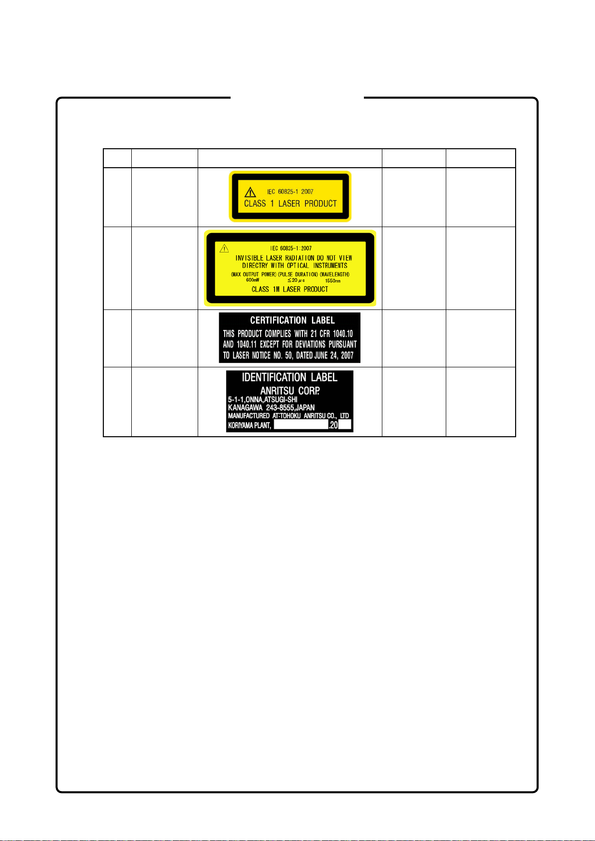
Table 3 Indication Labels on Product (Ex: Label list)
Type Sample Affixed to: Model Name
1 Explanation Figure 1, A MW9087B
2 Explanation
3 Certification
4 Identification
Figure 2, B MW9087D
Figure 2, C All Models
Figure 2, D All Models
vii

A
[1]
C
D
B
For Safety
Laser Radiatio n Markings
Figure 1 Locations of Laser Beam Apertures and Affixed Labels
Figure 2 Label Locations
viii
Disconnect from
Communication
Use in a
E
Use in
Atmospheres
For Safety
CAUTION
The OTDR Module outputs high-power optical pulses. Disconnect the
communication equipment from the optical fibers before a measurement,
or the optical sensor of the equipment may be broken.
Residential
nvironment
Corrosive
This equipment is designed for an industrial environment.
In a residential enviro nme n t, this equipment may cause radio
interference in which case the user may be required to take adequate
measures.
Exposure to corrosive gases such as hydrogen sulfide, sulfurous acid,
and hydrogen chloride will cause faults and failures.
Note that some organic solvents release corrosive gases.
ix

Equipment Certificate
Anritsu Corporation cer tifies that t his equip ment was tes ted before shi pment
using calibrated measuring instruments with direct traceability to public
testing organizations rec ognized by nationa l research laborator ies, including
the National Institute of Advanced Industrial Science and Technology, and
the National Institute of Information and Communications Technology, and
was found to meet the published specifications.
Anritsu Warranty
Anritsu Corporation will repair this equipment free-of-charge if a malfunction
occurs within one year after shipment due to a manufacturing fault, and
software bug fixes will be performed in accordance with the separate
Software End-User License Agreement, provide, however, that Anritsu
Corporation will deem this warranty void when:
● The fault is outside the scope of the warranty conditions separately
described in the operation manual.
● The fault is due to mishandling, misuse, or unauthorized modification or
repair of the equipment by the customer.
● The fault is due to severe usage clearly exceeding normal usage.
● The fault is due to improper or insufficient maintenance by the customer.
● The fault is due to natural disaster, including fire, wind or flood,
earthquake, lightning strike, or volcanic ash, etc.
● The fault is due to damage caused by acts of destruction, including civil
disturbance, riot, or war, etc.
● The fault is due to explosion, accident, or breakdown of any other
machinery, facility, or plant, etc.
● The fault is due to use of non-specified peripheral or applied equipment or
parts, or consumables, etc.
● The fault is due to use of a non-specified power supply or in a
non-specified installation location.
(Note)
● The fault is due to use in unusual environments
● The fault is due to activities or ingress of living organisms, such as insects,
spiders, fungus, pollen, or seeds.
In addition, this war ran ty is valid o nly f or t he orig inal e quipme nt purchas er. It
is not transferable if the equipment is resold.
Anritsu Corporation shal l assume no liability for damage or financial loss of
the customer due t o the us e of or a fa ilure to us e this equipment , unles s the
damage or l oss is caused due to Anri tsu Corporation’s intentional or gross
negligence.
.
x

Note:
For the purpose of this Warranty, "unusu al envir o nme n t s" means use:
● In places of direct sunlight
● In dusty places
● Outdoors
● In liquids, such as water, oil, or organic solvents, and medical fluids, or
places where these liquids may adhere
● In salty air or in place chemically active gases (sulfur dioxide, hydrogen
sulfide, chlorine, ammonia, nitrogen dioxide, or hydrogen chloride etc.)
are present
● In places where high-intensity static electric charges or electromagnetic
fields are present
● In places where abnormal power voltages (high or low) or instantaneous
power failures occur
● In places where condensation occurs
● In the presence of lubricating oil mists
● In places at an altitude of more than 2,000 m
● In the presence of frequent vibration or mechanical shock, such as in cars,
ships, or airplanes
Anritsu Corporation Contact
In the event of this equipment malfunctions, please contact an Anritsu
Service and Sales off ice. Contac t informat ion can be f ound on the last page
of the printed version of this manual, and is available in a separate file on the
PDF version.
xi

This product and its manuals may require an Export License/Approval by
the Government of the product's country of origin for re
country.
Before
whether they are export
When you dispose of export-controlled items, the products/manuals need
to be broken/shredded so as not to be unlawfully used for military
purpose.
Anritsu group promotes recycling activities in order to reuse available
resources and save energy. This product may use recycled parts
(mechanical components) that conform to Anritsu’s quality standards.
The life span of certain part s used in th is instrument is determin ed by the
operating time or the power-on time. Due consideration should be given to
the life spans of th ese parts when perf orming continuous oper ation over
an extended period. These parts must be replaced at the customer's
expense even if within the guaranteed period described in Warranty at the
beginning of this manual.
Notes On Export Management
-export from your
re-exporting the product or manuals, please contact us to confirm
-controlled items or not.
Reuse parts
Lifetime of Parts
xii

Crossed-out Wheeled Bin Symbol
Equipment marked w ith the Cr ossed-out Wheeled Bin Symbo l complies with
council directive 2012/19/EU (the “WEEE Directive”) in European Union.
For Products placed on the EU market after August 13 , 2005, pleas e contact
your local Anritsu representative at the end of the product's useful life to
arrange disposal in accor dance with your initial contract and the local law.
xiii

Software End-User License Agreement (EULA)
Please carefully read and accept this Software End-User License Agreement (hereafter this EULA)
before using (includes executing, copying, installing, registering, etc.) this Software (includes programs,
databases, scenarios, etc., used to operate, set, etc., Anritsu electronic equipment, etc.). By using this
Software, you shall be deemed to have agreed to be bound by the terms of this EULA, and Anritsu
Corporation (hereafter Anritsu) hereby grants you the right to use this Software with the Anritsu
specified equipment (hereafter Equipment) for the purposes set out in this EULA.
Article 1. Grant of License and Limitations
1. You may not to sell, transfer, rent, lease, lend,
disclose, sublicense, or otherwise distribute
this Software to third parties, whether or not
paid therefor.
2. You may make one copy of this Software for
backup purposes only.
3. You are not permitted to reverse engineer,
disassemble, decompile, modify or create
derivative works of this Software.
4. This EULA allows you to install one copy of
this Software on one piece of Equipment.
Article 2. Disclaimers
To the extent not prohibited by law, in no
event shall Anritsu be liable for direct, or any
incidental, special, indirect or consequential
damages whatsoever, including, without
limitation, damages for loss of profits, loss of
data, business interruption or any other
commercial damages or losses, and damages
claimed by third parties, arising out of or
related to your use or inability to use this
Software, unless the damages are caused due
to Anritsu’s intentional or gross negligence.
Article 3. Limitation of Liability
1. If a fault (bug) is discovered in this Software,
failing this Software to operate as described
in the operation manual or specifications
even though you have used this Software as
described in the manual, Anritsu shall at its
own discretion, fix the bug, or replace the
software, or suggest a workaround,
free-of-charge, provided, however, that the
faults caused by the following items and any
of your lost or damaged data whatsoever
shall be excluded from repair and the
warranty.
i) If this Software is deemed to be used for
purposes not described in the operation
manual or specifications.
ii) If this Software has been used in
conjunction with other
non-Anritsu-approved software.
iii) If this Software or the Equipment has
been modified, repaired, or otherwise
altered without Anritsu's prior
approval.
iv) For any other reasons out of Anritsu's
direct control and responsibility, such
as but not limited to, natural disasters,
software virus infections, or any devices
other than this Equipment, etc.
2. Expenses incurred for transport, hotel, daily
allowance, etc., for on-site repairs or
replacement by Anritsu engineers
necessitated by the above faults shall be
borne by you.
3. The warranty period for faults listed in
Section 1 of this Article shall be either 6
months from the date of purchase of this
Software or 30 days after the date of repair
or replacement, whichever is longer.
xiv

Article 4. Export Restrictions
You shall not use or otherwise export or
re-export directly or indirectly this Software
except as authorized by the laws and
regulations of Japan and the United States,
etc. In particular, this Software shall not be
exported or re-exported (a) into any Japan or
US embargoed countries or (b) to anyone
restricted by the Japanese export control
regulations, or the US Treasury
Department's list of Specially Designated
Nationals or the US Department of
Commerce Denied Persons List or Entity
List. In using this Software, you warrant
that you are not located in any such
embargoed countries or on any such lists.
You also agree that you will not use or
otherwise export or re-export this Software
for any purposes prohibited by the Japanese
and US laws and regulations, including,
without limitation, the development, design
and manufacture or production of missiles or
nuclear, chemical or biological weapons of
mass destruction, and conventional weapons.
Article 5. Change of Terms
Anritsu may change without your approval
the terms of this EULA if the changes are for
the benefit of general customers, or are
reasonable in light of the purpose of this
EULA and circumstances of the changes. At
the time of change, Anritsu will inform you of
those changes and its effective date, as a
general rule 45
website, or in writing or by e-mail.
days, in advance on its
Article 6. Termination
1. Anritsu may terminate this EULA
immediately if you violate any conditions
described herein. This EULA shall also be
terminated immediately by Anritsu if there
is any good reason that it is deemed difficult
to continue this EULA, such as your
violation of Anritsu copyrights, patents, etc.
or any laws and ordinances, or if it turns out
that you belong to an antisocial organization
or has a socially inappropriate relationship
with members of such organization.
2. You and Anritsu may terminate this EULA
by a written notice to the other party 30 days
in advance.
Article 7. Damages
If Anritsu suffers any damages or loss,
financial or otherwise, due to your violation
of the terms of this EULA, Anritsu shall have
the right to seek proportional damages from
you.
Article 8. Responsibility after Termination
Upon termination of this EULA in
accordance with Article 6, you shall cease all
uses of this Software immediately and shall
as directed by Anritsu either destroy or
return this Software and any backup copies,
full or partial, to Anritsu.
Article 9. Negotiation for Dispute
Resolution
If matters of interpretational dispute or
items not covered under this EULA arise,
they shall be resolved by negotiations in good
faith between you and Anritsu.
Article 10. Governing Law and Court of
Jurisdiction
This EULA shall be governed by and
interpreted in accordance with the laws of
Japan without regard to the principles of the
conflict of laws thereof, and any disputes
arising from or in relation to this EULA that
cannot be resolved by negotiation described
in Article 9 shall be subject to and be settled
by the exclusive agreed jurisdiction of the
Tokyo District Court of Japan.
Revision History:
February 29th, 2020
xv

virus security protection in
place.
Cautions Against Computer Virus Infection
● Copying files and dat a
Only files that have been provided directly from Anritsu or generated
using Anritsu equipment should be copied to the instrument.
All other required files should be transferred by means of USB flash
drive or CompactFlash media after undergoing a thorough virus
check.
● Adding software
Do not download or install software that has not been specifically
recommended or licensed by Anritsu.
● Network connections
Ensure that the network has sufficient anti-
xvi

CE Conformity Marking
Anritsu affixes the CE conformity marking on the following product(s) in
accordance with the Decision 768/2008/EC to indicate that they conform
to the EMC, LVD, and RoHS directive of the European Union (EU).
CE marking
1. Product Model
Model: MW9087 Series Card OTDR
2. Applied Directive
EMC: Directive 2014/30/EU
LVD: Directive 2014/35/EU
RoHS: Directive 2011/65/EU
3. Applied Standards
EMC: Emission: EN 61326-1: 2013 (Class A)
•
Immunity: EN 61326-1: 2013 (Table 2)
Performance Criteria*
IEC 61000-4-2 (ESD) B
IEC 61000-4-3 (EMF) A
IEC 61000-4-4 (Burst) B
IEC 61000-4-5 (Surge) B
IEC 61000-4-6 (CRF) A
IEC 61000-4-11 (V dip/short) B, C
*: Performance Criteria
A: The equipment shall continue to operate as intended during and
after the test. No degradation of performance or loss of function
is allowed below a performance level specified by the
manufacturer, when the equipment is used as intended.
The performance level may be replaced by a permissible loss of
performance. If the minimum performance level or the
permissible performance loss is not specified by the
manufacturer, either of these may be derived from the product
description and documentation and what the user may
reasonably expect from the equipment if used as intended.
xvii
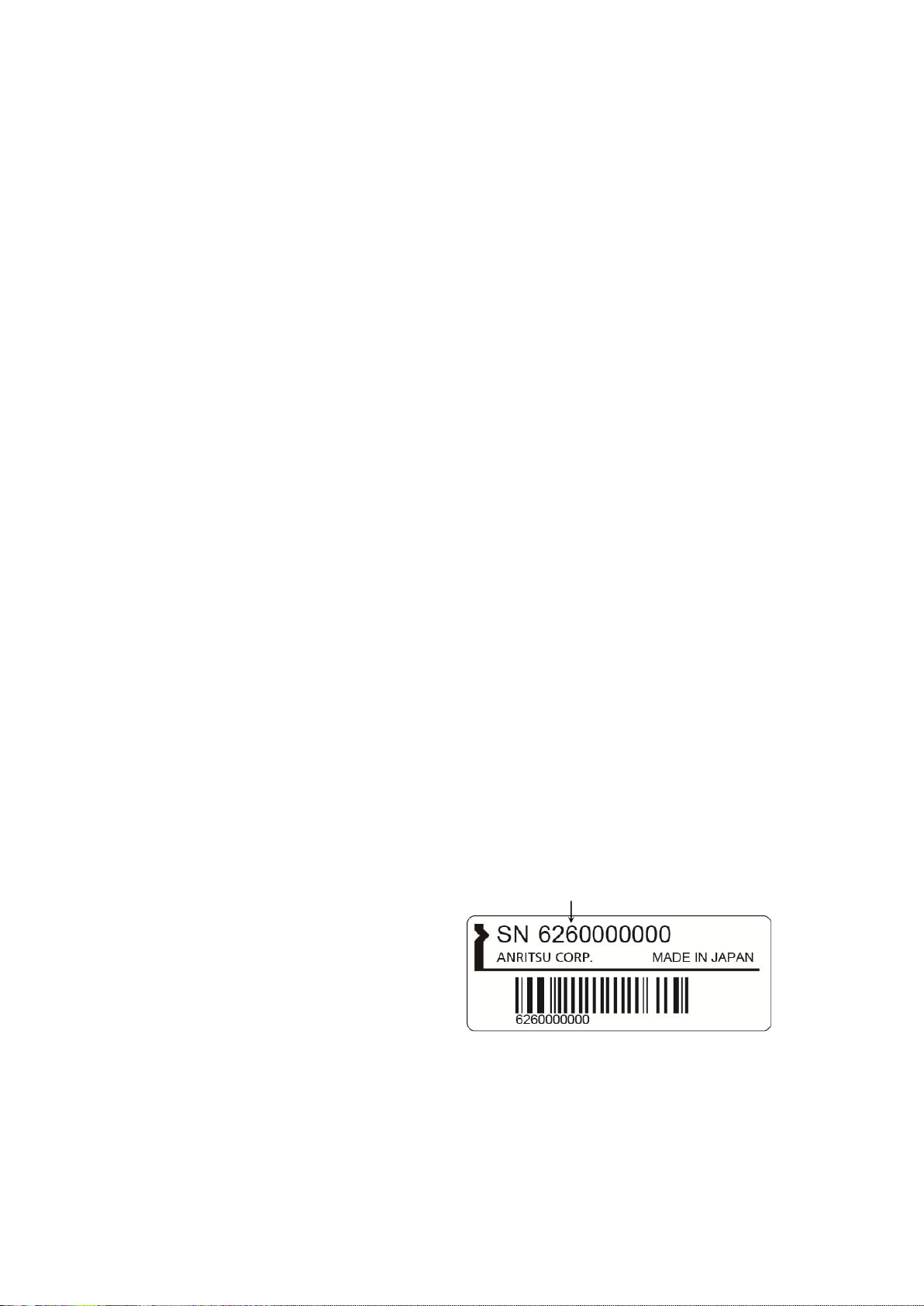
Serial number example
If the third digit of the serial number is "7", the product
complies with Directive 2011/65/EU as amended by (EU)
2015/863.
(Pb,Cd,Cr6+,Hg,PBB,PBDE,DEHP,BBP,DBP,DIBP)
If the third digit of the serial number is "6", the product
complies with Directive 2011/65/EU.
(Pb,Cd,Cr6+,Hg,PBB,PBDE)
Third digit
B: The equipment shall continue to operate as intended after the
test. No degradation of performance or loss of function is
allowed below a performance level specified by the
manufacturer, when the equipment is used as intended.
The performance level may be replaced by a permissible loss of
performance. During the test, degradation of performance is
however allowed. No change of actual operating state or stored
data is allowed. If the minimum performance level or the
permissible performance loss is not specified by the
manufacturer, either of these may be derived from the product
description and documentation and what the user may
reasonably expect from the equipment if used as intended.
C: Temporary loss of function is allowed, provided the function is
self-recoverable or can be restored by the operation of the
controls.
Harmonic current emiss ion s :
EN 61000-3-2: 2014 (Class A equipment)
No limits apply to this equipment with an active input
power under 75 W.
LVD: EN 61010-1: 2010 (Pollution Degree 2)
•
RoHS: EN 50581: 2012 (Catego r y 9)
•
xviii

4. Contact
Name: Anritsu GmbH
Address, city: Nemetschek Haus, Konrad-Zuse-Platz 1
81829 München,
Country: Germany
Name: ANRI T SU EM EA Lt d.
Address, city: 200 Capability Green, Luton
Bedfordshire, LU1 3LU
Country: United Kingdom
xix

RCM Conformity Marking
Anritsu affixes the RCM mark on the following product(s) in accordance
with the regulation to indicate that they conform to the EMC framework of
Australia/New Zealand.
RCM marking
1. Product Model
Model: MW9087 Series Card OTDR
2. Applied Standards
EMC: Emission: EN 61326-1: 2013 (Class A equipment)
xx
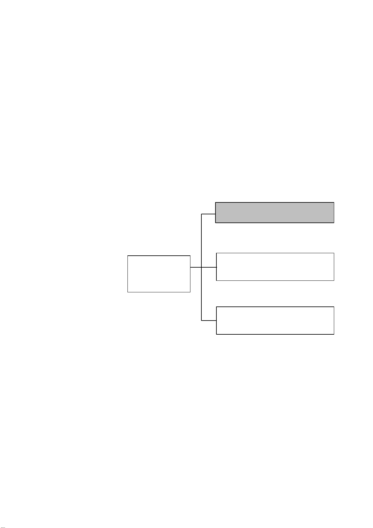
About This Manual
The configuration of the MW9087 Series Card OTDR operation manual is
divided into the following three parts: Card OTDR Mainframe, LED
Interface, and Password function.
This manual describes the operation/maintenance method for MW9087
Series Card OTDR.
Refer to Chapter 2 "Before Use" to understand the setting of this device
and precautions.
Also, refer to Chapter 3 "Measurement Method" to understand the
overview of operation flow.
MW9087 Series
Operation Manual
Configuration
MW9087 Series Card OTDR
Operation Manual (This manual)
Describes basic operations of
MW9087 Series Card OTDR
MW9087 Series Card OTDR
Option 001 LED Interface
Operation Manual
Described the operation method of
the LED interface.
MW9087 Series Card OTDR
Password Function Option
Operation Manual
Describes the operation method of
the password functio n.
I

Table of Contents
For Safety .................................................... iii
About This Manual........................................ I
Chapter 1 Outline ....................................... 1-1
1.1 Introduction to MW9087 Series Card OTDR ............. 1-2
1.2 Features ..................................................................... 1-3
1.3 Outline of OTDR ........................................................ 1-5
Chapter 2 Before Use ................................. 2-1
2.1 Product Configuration ................................................ 2-2
2.2 Names of Parts .......................................................... 2-3
2.3 Installing the Card OTDR ........................................... 2-5
2.4 Power Connection ..................................................... 2-8
2.5 Communication Settings ............................................ 2-9
2.6 Installation/Uninstallation for USB Serial Driver ........ 2-11
2.7 Confirmation of COM Ports ........................................ 2-25
2.8 Connecting the Optical Fiber Cable ........................... 2-29
2.9 Cautions on Handling Optical Fiber Cables ............... 2-31
2.10 Replacing the Optical Connector ............................... 2-33
2.11 Precautions ................................................................ 2-34
II
Chapter 3 Measurement Method ............... 3-1
3.1 Setting before Measurement ..................................... 3-2
3.2 Measurement Procedures ......................................... 3-3
3.3 Setting Measurement Conditions............................... 3-4
3.4 Measurement ............................................................. 3-5
3.5 Waveform Analysis .................................................... 3-6
3.6 Calculation Method .................................................... 3-7
3.7 Obtaining State .......................................................... 3-14

1
Chapter 4 Command Reference ................ 4-1
4.1 Command Format ...................................................... 4-2
4.2 Transmission Procedures .......................................... 4-3
4.3 Command List ............................................................ 4-5
4.4 Command Details ...................................................... 4-15
4.5 Error Code ................................................................. 4-53
Chapter 5 Performance Test and
Maintenance .............................. 5-1
5.1 Performance Test ...................................................... 5-2
5.2 Updating Software ..................................................... 5-16
5.3 Cautions on Storage .................................................. 5-17
5.4 Transporting and Disposal ......................................... 5-18
2
3
4
5
Appendix
Appendix A Specifications ......................... A-1
Appendix B Relationship between Pulse
Width Distance Range ............ B-1
Appendix C Factory Shipment Defaults .... C-1
Appendix D Command Compatibility ........ D-1
Appendix E Performance Test Result
Form ........................................ E-1
III

IV.

Chapter 1 Outline
1-1
Outline
This chapter explains the features of the MW9087 Series Card OTDR
Introduction to MW9087 Series Card OTDR ............. 1-2
1.1
1.2 Features ..................................................................... 1-3
1.3 Outline of OTDR ........................................................ 1-5
1

Chapter 1 Outline
1-2
MW9087B
1650 nm
41 dB
MW9087D
1550 nm
50 dB
1.1 Introduction to MW9087 Series Card OTDR
MW9087 Series Card OTDR is a module form for the optical fiber
measurement device.
Figure 1.1-1 Card OTDR Appearance (MW9087B)
This device has multiple models depending on wavelengths and dynamic
ranges.
1550 nm wavelength is used for communications.
To monitor the fiber loss/deterioration or breaks without effects on
communications, the model with wavelength of 1650 nm is used.
To measure the fiber loss of the wavelength used for communications, the
model with wavelength of 1550 nm is used.
If the fiber loss is large or the communication path has the fiber loss due
to optical coupler, the model with a large dynamic range is used.
Table 1.1-1 Model Name of Card OTDR
Model Wavelength Dynamic range
(Typ.)
1.2 Features
1-3
Outline
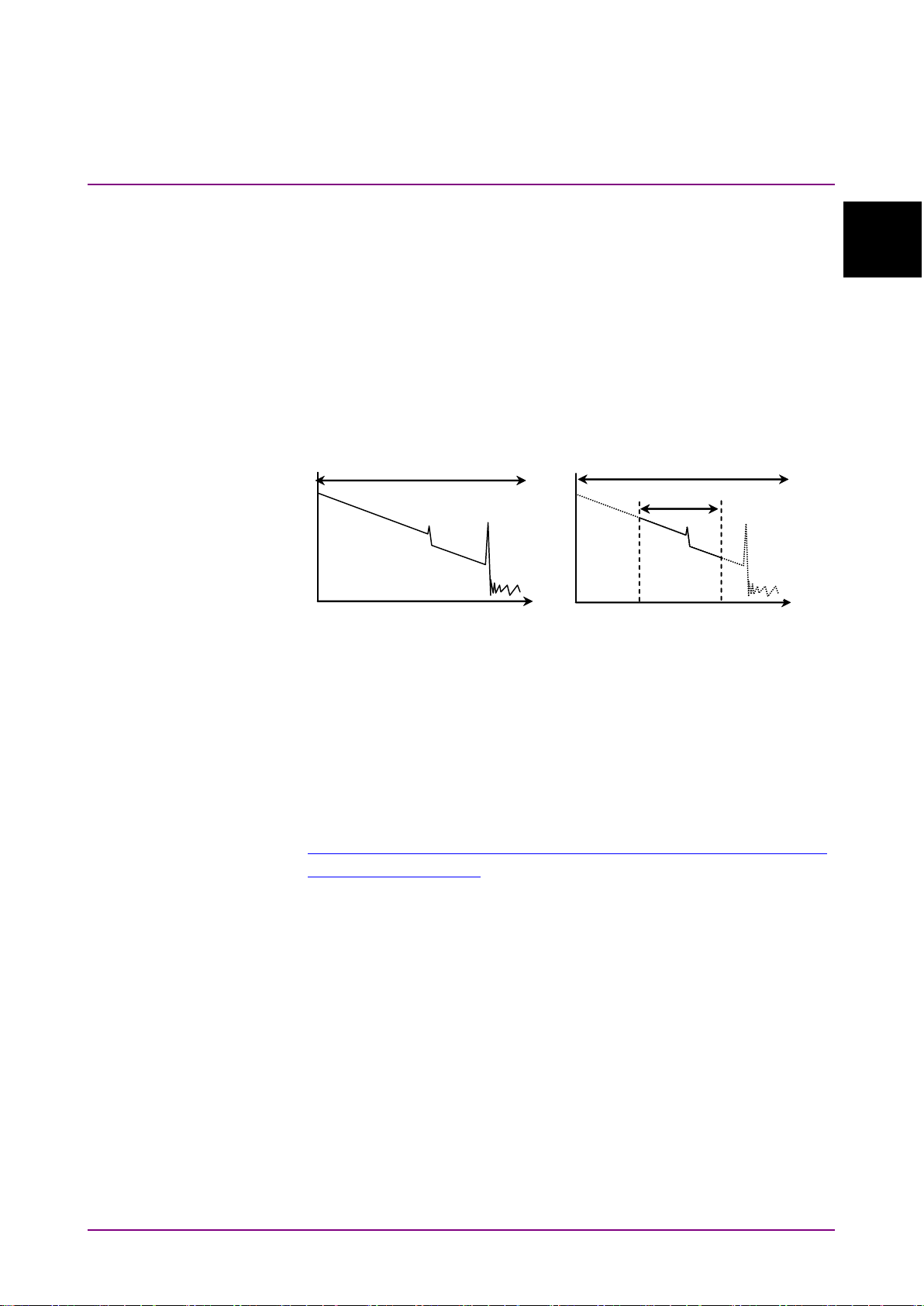
1.2 Features
Normal measurement
Partial sampling
Distance range
Distance range
Measurement range
Distance
Distance
The MW9087 Series Card OTDR has been developed in order to monitor
faults in the optical fiber system.
You can control it via Ethernet; therefore, it can be used for
automatic/remote measurement.
1
Partial sampling
Distance range to be measured can be set, and only the range set can be
measured. This feature will shorten the measurement time.
Figure 1.2-1 Normal Measurement and Partial Sampling
SR-4731 file format
The measurement results can be saved with Telcordia standard SR-4731
OTDR Data Format-compliant files. These files have the extension of
SOR, and waveforms can be displayed with TraceView software.
This software is available from the following URL.
http://www.anritsu.com/en-US/Downloads/Software/Drivers/Software-Do
wnloads/DWL2761.aspx

Chapter 1 Outline
1-4
Figure 1.2-2 Waveform Display with TraceView software
Note:
The obtained waveform using the partial sampling cannot be
displayed with the Trace View software properly.
1.3 Outline of OTDR
1-5
Outline
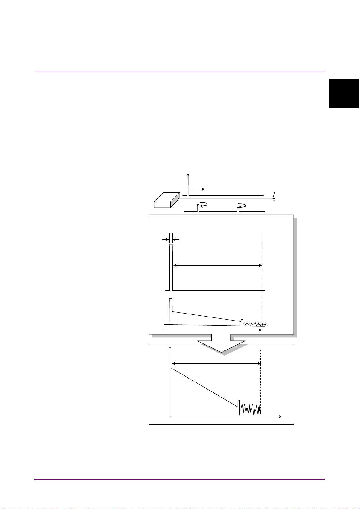
1.3 Outline of OTDR
Level
Time
Transmitted light
level
Received light
level
Measurement time
Pulse width
Distance range
Distance
OTDR
Fiber
Time change between the light pulse transmitted
and the light level received by OTDR
Waveform data of OTDR
OTDR operating principle
OTDR (Optical Time Domain Reflectometer) transmits brief optical
pulses to the fiber to measure the intensity and time difference of lights
reflected from within the fiber.
The distance of the reflection point is calculated from the time difference,
light speed, and index of refraction (IOR) of the fiber.
The light attenuation (fiber loss) is calculated from the light intensity
reflected from within the fiber.
1
Figure 1.3-1 OTDR Transmitted/Received Waveform and
Waveform Data
Chapter 1 Outline
1-6
Level
Loss occurred
Distance
Reflection occurred
When pulse width is large
Distance
Level
When pulse width is narrow
Distance
The maximum measurable distance (distance range) is determined by the
time when OTDR measures the received light level after the optical pulse
is transmitted.
Transmitted optical pulse is reflected little by little within the fiber. The
more distant the reflected light is, the lower is the light level received by
OTDR. Therefore, the waveform of measurement result becomes a
downward-sloping rectilinear graph.
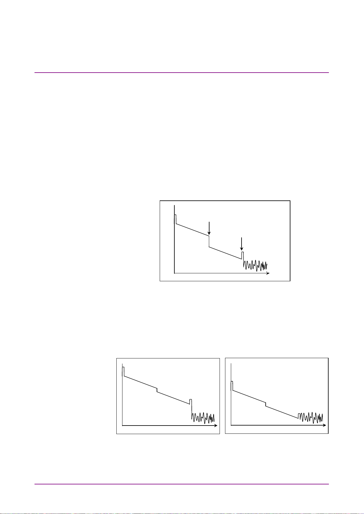
OTDR fiber measurement
In places where the fiber is connected or damaged, the fiber loss or the
light reflection may become larger. These changes make the waveform of
measurement result discontinuous.
Figure 1.3-2 Detection of Fiber Loss and Reflection
Waveform change with pulse width
The larger is the transmitted optical pulse width, the higher is the
received light level. Therefore, make the pulse width larger for the
measurement system with large fiber loss such as the case of a long
distance range.
Figure 1.3-3 Level Change with Pulse Width
 Loading...