

Page 1

Network Master Series
µ
Operation Manual
23rd Edition
●
This document explains the operation of the
,
●
●
MU909014A/A1/B/B1/C/C6
MU909015A6/B/B1/C/C6
OTDR Module
MT9090A main frame, MU909014A/A1/B/B1/C/C6
MU909015A6/B/B1/C/C6 µOTDR modules
For safety and warning information, please read this
manual before attempting to use the equipment.
Keep this manual with the equipment.
.
ANRITSU CORPORATION
Document No.: M-W3586AE-23.0
Page 2
Safety Symbols
DANGER
WARNING
CAUTION
To prevent the risk of personal injury or loss related to equipment malfunction, Anritsu Corporation uses the following
safety symbols to indicate safety-related information. Ensure that you clearly understand the meanings of the
symbols BEFORE using the equipment. Some or all of the following symbols may be used on all Anritsu equipment.
In addition, there may be other labels attached to products that are not shown in the diagrams in this manual.
Symbols used in manual
This indicates a very dangerous procedure that could result in serious injury or
death if not performed properly.
This indicates a hazardous procedure that could result in serious injury or death if
not performed properly.
This indicates a hazardous procedure or danger that could result in light-to-severe
injury, or loss related to equipment malfunction, if proper precautions are not taken.
Safety Symbols Used on Equipment and in Manual
The following safety symbols are used inside or on the equipment near operation locations to provide information
about safety items and operation precautions. Ensure that you clearly understand the meanings of the symbols and
take the necessary precautions BEFORE using the equipment.
This indicates a prohibited operation. The prohibited operation is indicated
symbolically in or near the barred circle.
This indicates an obligatory safety precaution. The obligatory operation is indicated
symbolically in or near the circle.
This indicates a warning or caution. The contents are indicated symbolically in or
near the triangle.
This indicates a note. The contents are described in the box.
These indicate that the marked part should be recycled.
Network Master Series
MU909014A/A1/B/B1/C/C6, MU909015A6/B/B1/C/C6
OTDR Module
µ
Operation Manual
15 January 2012 (First Edition)
8 January 2021 (23rd Edition)
Copyright © 2012-2021, ANRITSU CORPORATION.
All rights reserved. No part of this manual may be reproduced without the prior written permission of the
publisher.
The operational instructions of this manual may be changed without prior notice.
Printed in Japan
ii
Page 3
Replacing Battery
Battery Disposal
For Safety
DANGER
● When replacing the battery, use the specified battery and insert it with
the correct polarity. If the wrong battery is used, or if the battery is
inserted with reversed polarity, there is a risk of explosion causing
severe injury or death.
● DO NOT expose batteries to heat or fire. This is dangerous and can
result in explosions or fire. Heating batteries may cause them to leak
or explode.
WARNING
Repair
● ALWAYS refer to the operation manual when working near locations
at which the alert mark shown on the left is attached. If the advice in
the operation manual is not followed, there is a risk of personal injury
or reduced equipment performance. The alert mark shown on the left
may also be used with other marks and descriptions to indicate other
dangers.
● Overvoltage Category
This equipment complies with overvoltage category II defined in IEC
61010. DO NOT connect this equipment to the power supply of
overvoltage category III or IV.
● Laser radiation warning
- NEVER look directly into the cable connector on the equipment
nor into the end of a cable connected to the equipment. There is a
risk of injury if laser radiation enters the eye.
- The Laser Safety label is attached to the equipment for safety use
as indicated in "Laser Safety" later in this section.
● Only qualified service personnel with a knowledge of electrical fire and
shock hazards should service this equipment. This equipment cannot
be repaired by the operator. DO NOT attempt to remove the equipment
covers or unit covers or to disassemble internal components. There are
high-voltage parts in this equipment presenting a risk of severe injury
or fatal electric shock to untrained personnel. In addition, there is a risk
of damage to precision components.
iii
Page 4

Battery Fluid
LCD
High
For Safety
WARNING
Calibration
temperature
● The performance-guarantee seal verifies the integrity of the equipment.
To ensure the continued integrity of the equipment, only Anritsu service
personnel, or service personnel of an Anritsu sales representative,
should break this seal to repair or calibrate the equipment. Be careful
not to break the seal by opening the equipment or unit covers. If the
performance-guarantee seal is broken by you or a third party, the
performance of the equipment cannot be guaranteed.
● DO NOT short the battery terminals and never attempt to disassemble
the battery or dispose of it in a fire. If the battery is damaged by any of
these actions, the battery fluid may leak.
This fluid is poisonous.
DO NOT touch the battery fluid, ingest it, or get in your eyes. If it is
accidentally ingested, spit it out immediately, rinse your mouth with
water and seek medical help. If it enters your eyes accidentally, do
not rub your eyes, rinse them with clean running water and seek
medical help. If the liquid gets on your skin or clothes, wash it off
carefully and thoroughly with clean water.
● This equipment uses a Liquid Crystal Display (LCD). DO NOT subject
the equipment to excessive force or drop it. If the LCD is subjected to
strong mechanical shock, it may break and liquid may leak.
This liquid is very caustic and poisonous.
DO NOT touch it, ingest it, or get in your eyes. If it is ingested
accidentally, spit it out immediately, rinse your mouth with water and
seek medical help. If it enters your eyes accidentally, do not rub your
eyes, rinse them with clean running water and seek medical help. If
the liquid gets on your skin or clothes, wash it off carefully and
thoroughly with soap and water.
● Turn off the unit and allow alkaline batteries to cool before touching or
removing. The temperature of batteries may rise by approximately
+20°C if used continuously for an extended period of time.
iv
Page 5
For Safety
Class 1, 1M and 3R indicate the danger degree of the laser radiation
Laser Safety
specified below according to IEC 60825-1:2007.
Class 1: Lasers that are safe under reasonably foreseeable conditions
of operation, including the use of optical instruments for
intrabeam viewing.
Class 1M: Lasers emitting in the wavelength range from 302.5 to 4000
nm that are safe under reasonably foreseeable conditions of
operation, but may be hazardous if the user employs optics
within the beam. Two conditions apply:
a) for diverging beams, if the user views the laser output with
certain optical instruments (for example, eye loupes,
magnifiers and microscopes) within a distance of 100 mm;
or
b) for collimated beams, if the user views the laser output with
certain optical instruments (for example, telescopes and
binoculars).
Class 3R: Lasers that emit in the wavelength range from 302.5 to 10
where direct intrabeam viewing is potentially hazardous but
the risk is lower than for Class 3B lasers.
6
nm
CAUTION
Use of controls or adjustments or performance of procedures other than
those specified herein may result in hazardous radiation exposure.
The use of optical instruments with this product will increase eye hazard.
v
Page 6
For Safety
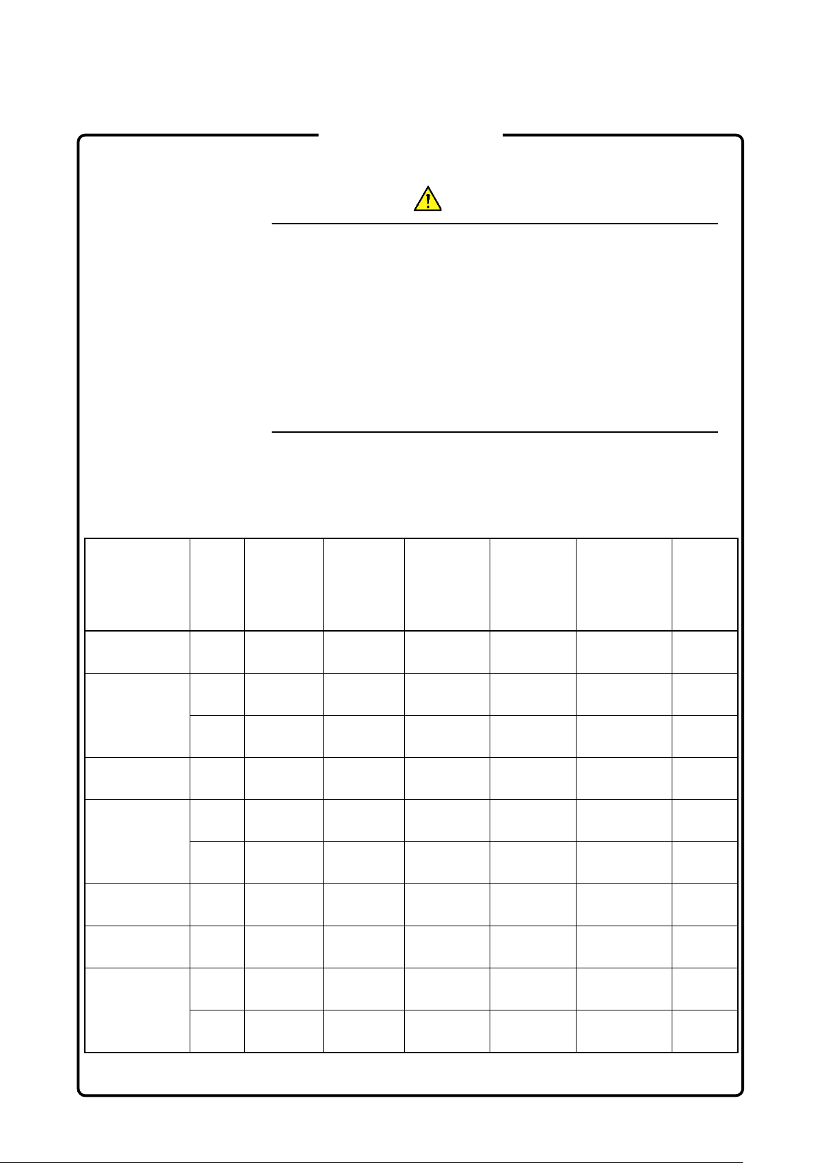
WARNING
Laser Safety
Model Name Class
Before using this instrument, always ensure that the warning light is lit
when the optical output switch is turned on. If this warning light does not
turn on, the equipment may be faulty and for safety reasons should be
returned to an Anritsu service center or representative for repair.
The laser in this equipment is classified as Class 1, 1M, or 3R according
to the IEC 60825-1: 2007 standard.
Never use optical instruments to directly view Class 1M laser products.
Doing so may result in serious damage to the eyes.
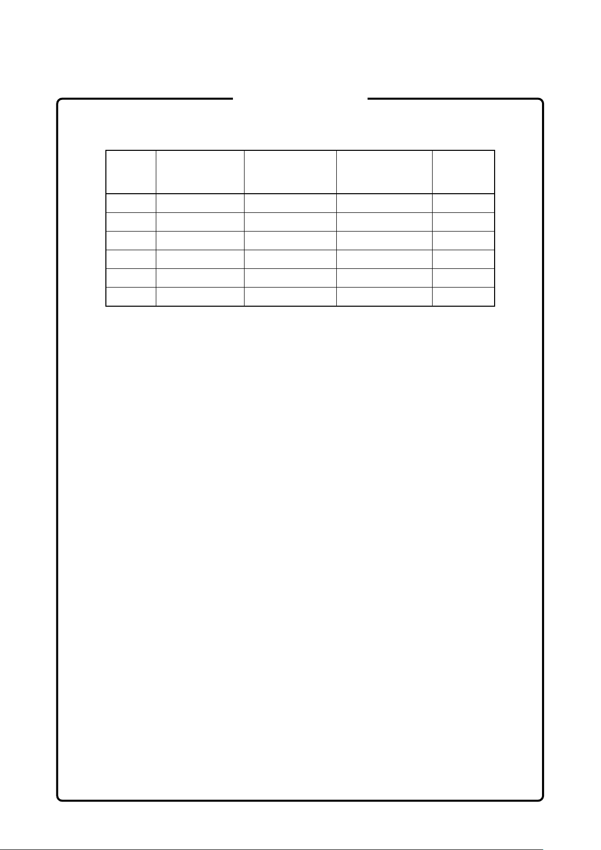
Table 1 Laser Safety Classifications Based on IEC 60825-1:2007
Max.
Optical
Output
Power
(W)*
Pulse
Width(s)/
Repetition
Rate
Emitted
Wavelength
(nm)
Beam
Divergence
(deg)
Incorporated
Laser
Specification
(refer to
Table 2)
Laser
Aperture
MU909014A
-053/063
MU909014A1
-053/063
MU909014A
-054/064
MU909014A1
-054/064
MU909015A6-
053/063
MU909015A6-
054/064
MU909014B
MU909015B
-056/066
1 0.15
1 0.15
3R 0.003 CW 650 11.5 f)
1 0.15
1 0.15
3R 0.003 CW 650 11.5 f)
1 0.15
1 0.15
1M 0.15
1 0.15
20×10–6/
0.009
–6
20×10
0.009
20×10–6/
0.009
–6
20×10
0.009
20×10–6/
0.009
20×10–6/
0.009
–6
20×10
0.015
–6
20×10
0.009
1625 11.5 d)
/
/
/
/
1625 11.5 d)
1650 11.5 e)
1650 11.5 e)
1625 11.5 d)
1650 11.5 e)
1310 11.5 a)
1550 11.5 c)
Figure
1, [1]
Figure
2, [1]
Figure
2, [2]
Figure
1, [1]
Figure
2, [1]
Figure
2, [2]
Figure
1, [1]
Figure
1, [1]
Figure
1, [1]
Figure
1, [1]
vi
Page 7

For Safety
Table 1 Laser Safety Classifications Based on IEC 60825-1:2007 (Continued)
Model Name
MU909014B1
MU909015B1
-056/066
MU909014C/C6
MU909015C/C6
-057/067
MU909014C/C6
MU909015C/C6
-058/068
MU909015C
-059/069
MU909015C6
-059/069
Max.
Optical
Class
Output
Power
(W)*
1M 0.15
1 0.15
Pulse
Width(s)/
Repetition
Rate
–6
20×10
/
0.015
–6
20×10
/
0.009
Emitted
Wavelength
(nm)
Beam
Divergence
(deg)
1310 11.5 a)
1550 11.5 c)
Incorporated
Laser
Specification
(refer to
Table 2)
3R 0.003 CW 650 11.5 f)
–6
1M 0.15
1 0.15
1 0.15
1M 0.15
1 0.15
1 0.15
1M 0.15
1 0.15
1 0.15
1M 0.15
1 0.15
1 0.15
20×10
20×10
20×10
20×10
20×10
20×10
20×10
20×10
20×10
20×10
20×10
20×10
0.015
0.009
0.009
0.015
0.009
0.009
0.015
0.009
0.009
0.015
0.009
0.009
/
–6
/
–6
/
–6
/
–6
/
–6
/
–6
/
–6
/
–6
/
–6
/
–6
/
–6
/
1310 11.5 a)
1550 11.5 c)
1625 11.5 d)
1310 11.5 a)
1550 11.5 c)
1650 11.5 e)
1310 11.5 a)
1490 11.5 b)
1550 11.5 c)
1310 11.5 a)
1490 11.5 b)
1550 11.5 c)
Laser
Aperture
Figure
2, [1]
Figure
2, [1]
Figure
2, [2]
Figure
3, [1]
Figure
3, [1]
Figure
3, [2]
Figure
3, [1]
Figure
3, [1]
Figure
3, [2]
Figure
1, [1]
Figure
1, [1]
Figure
1, [1]
Figure
3, [1]
Figure
3, [1]
Figure
3, [1]
*: Indicates the possible optical output power when each and every
reasonably foreseeable single-fault condition is included.
vii
Page 8
For Safety
Table 2 Incorporated Laser Specifications
Incorpor
ated
Laser
a) 0.3 20×10–6/0.015 1310 11.5
b) 0.3 20×10–6/0.009 1490 11.5
c) 0.3 20×10–6/0.009 1550 11.5
d) 0.3 20×10–6/0.009 1625 11.5
e) 0.3 20×10–6/0.009 1650 11.5
f) 0.003 CW 650 11.5
Max. Optical
Output Power
1
(W)*
*1: Maximum output power is the estimated value when something
breaks down.
*2: This product incorporates a laser diode module with optical fiber
output.
Pulse Width
(s)/Repetition
Rate
Emitted
Wavelength (nm)
Divergence
Beam
(deg)
*2
viii
Page 9
For Safety
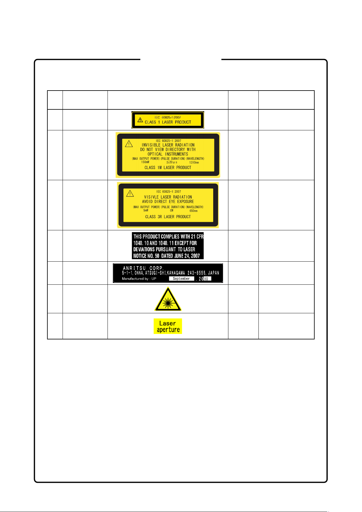
Table 3 Labels on Product
Type Label
1 Explanation
2 Explanation
3 Explanation
4 Certification
5 Identification
Affixed
to:
Figure 4,
A
Figure 4,
B
Figure 4,
C
Figure 4,
D
Figure 4,
E
Model Name
MU909014A
MU909015A6
MU909014B/C/C6
MU909015B/C/C6
MU909014A1/
MU909014B1/
MU909015B1
All models
All models
6 Warning
7 Aperture
Figure 4,
F
Figure 4,
G
MU909014A1/
MU909014B1/
MU909015B1
MU909014A1/
MU909014B1/
MU909015B1
ix
Page 10
[1]
[2]
[1]
[2]
[1]
For Safety
Laser Radiation Markings
Figure 1 Locations of Laser Beam Apertures (MU909014A/B MU909015A6/B and
MU909015C-059/069)
Figure 2 Locations of Laser Beam Apertures (MU909014A1/B1 and MU909015B1)
Figure 3 Locations of Laser Beam Apertures (MU909014C/C6 and MU909015C/C6)
x
Page 11
A
E
C
G
B
F
Laser
aperture
D
For Safety
Figure 4 Locations of Affixed Labels
xi
Page 12
Ni-MH
For Safety
FOR U.S. CUSTOMERS
Please Recycle.
The product that you have purchased contains a rechargeable battery.
The battery is recyclable. At the end of its useful life, under various state
and local laws, it may be illegal to dispose of this battery into the
municipal waste stream. Check with your local solid waste officials for
details in your area for recycling options or proper disposal.
Before disposing of this product, discharge the battery and mail it to your
Anritsu Service or Sales office.
1. Attach the battery pack to the product.
2. Disconnect the AC adapter, if used.
3. Turn the power switch to on.
4. Set Auto Backlight to
5. Leave the product on until the power indicator goes off; the battery is
now discharged.
6. Remove the battery.
7. Insulate the battery terminals with adhesive tape.
8. Mail it to your Anritsu Service or Sales office, or to the following
address.
ANRITSU COMPANY
490 Jarvis Drive, Morgan Hill, CA 95037-2809, USA
and Auto Power Off to
Off
Off
.
xii
Page 13

Ni-MH
For Safety
FOR EU & EFTA CUSTOMERS
Please Recycle.
Read the following when using products to which the mark shown on the
above is attached.
The product that you have purchased contains a rechargeable battery.
The battery is recyclable. At the end of its useful life, under various state
and local laws, it may be illegal to dispose of this battery into the
municipal waste. Check with your local solid-waste disposal officials for
details of recycling options or proper disposal in your area.
Before disposing of this product, discharge the battery and mail it to your
Anritsu Service or Sales office.
1. Disconnect the AC adapter, if used.
2. Turn the power switch to on.
3. Leave the product on until the power indicator goes off; the battery is
now discharged.
4. Remove the battery.
5. Insulate the battery terminals with adhesive tape.
6. Please recycle in accordance with your national or regional
legislation.
Nach Gebrauch der Ver Kaufsstelle Zurückgeben.
Après usage à rapporter au point de vente.
xiii
Page 14

External
Storage Media
Hard disk
Use in a
E
Use in
Atmospheres
For Safety
CAUTION
This equipment uses a USB flash drive as external storage media for
storing data and programs. If this media is mishandled or becomes faulty,
important data may be lost.
It is recommended to periodically back up all important data and
programs to protect them from being lost accidentally.
Anritsu will not be held responsible for lost data.
Pay careful attention to the following points.
● Never remove the USB flash drive from the equipment while it is
being accessed.
● The USB flash drive may be damaged by static electric charges.
● Anritsu has thoroughly tested all external storage media shipped with
this equipment. Users should note that external storage media not
shipped with this equipment may not have been tested by Anritsu,
thus Anritsu cannot guarantee the performance or suitability of such
media.
The equipment is uses internal flash memory for storing data and
programs. If this media is mishandled or becomes faulty, important data
may be lost. It is recommended to periodically back up all important data
and programs to protect them from being lost accidentally.
Anritsu will not be held responsible for lost data.
xiv
Residential
nvironment
Corrosive
To reduce the possibility of data loss, particular attention should be given
to the following points.
● The equipment should only be used within the recommend
temperature range, and should not be used in locations where the
temperature may fluctuate suddenly.
● Exercise care not to bang or shake the equipment whilst the power is
on.
This equipment is designed for an industrial environment.
In a residential environment, this equipment may cause radio
interference in which case the user may be required to take adequate
measures.
Exposure to corrosive gases such as hydrogen sulfide, sulfurous acid,
and hydrogen chloride will cause faults and failures.
Note that some organic solvents release corrosive gases.
Page 15

Equipment Certificate
Anritsu Corporation certifies that this equipment was tested before shipment
using calibrated measuring instruments with direct traceability to public
testing organizations recognized by national research laboratories, including
the National Institute of Advanced Industrial Science and Technology, and
the National Institute of Information and Communications Technology, and
was found to meet the published specifications.
Anritsu Warranty
Anritsu Corporation will repair this equipment free-of-charge if a malfunction
occurs within one year after shipment due to a manufacturing fault, and
software bug fixes will be performed in accordance with the separate
Software End-User License Agreement, provide, however, that Anritsu
Corporation will deem this warranty void when:
● The fault is outside the scope of the warranty conditions separately
described in the operation manual.
● The fault is due to mishandling, misuse, or unauthorized modification or
repair of the equipment by the customer.
● The fault is due to severe usage clearly exceeding normal usage.
● The fault is due to improper or insufficient maintenance by the customer.
● The fault is due to natural disaster, including fire, wind or flood,
earthquake, lightning strike, or volcanic ash, etc.
● The fault is due to damage caused by acts of destruction, including civil
disturbance, riot, or war, etc.
● The fault is due to explosion, accident, or breakdown of any other
machinery, facility, or plant, etc.
● The fault is due to use of non-specified peripheral or applied equipment or
parts, or consumables, etc.
● The fault is due to use of a non-specified power supply or in a
non-specified installation location.
● The fault is due to use in unusual environments
● The fault is due to activities or ingress of living organisms, such as insects,
spiders, fungus, pollen, or seeds.
In addition, this warranty is valid only for the original equipment purchaser. It
is not transferable if the equipment is resold.
Anritsu Corporation shall assume no liability for damage or financial loss of
the customer due to the use of or a failure to use this equipment, unless the
damage or loss is caused due to Anritsu Corporation’s intentional or gross
negligence.
(Note)
.
xv
Page 16

Note:
For the purpose of this Warranty, "unusual environments" means use:
● In places of direct sunlight
● In dusty places
● In liquids, such as water, oil, or organic solvents, and medical fluids, or
places where these liquids may adhere
● In salty air or in place chemically active gases (sulfur dioxide, hydrogen
sulfide, chlorine, ammonia, nitrogen dioxide, or hydrogen chloride etc.)
are present
● In places where high-intensity static electric charges or electromagnetic
fields are present
● In places where abnormal power voltages (high or low) or instantaneous
power failures occur
● In places where condensation occurs
● In the presence of lubricating oil mists
● In places at an altitude of more than 2,000 m
● In the presence of frequent vibration or mechanical shock, such as in cars,
ships, or airplanes
Anritsu Corporation Contact
In the event of this equipment malfunctions, please contact an Anritsu
Service and Sales office. Contact information can be found on the last page
of the printed version of this manual, and is available in a separate file on the
PDF version.
xvi
Page 17

This product and its
the Government of the product's country of origin for re
country.
Before re
whethe
W
controlled items, the products/manuals need
to be broken/shredded so as not to be unlawfully used for military
purpose.
Notes On Export Management
manuals may require an Export License/Approval by
-export from your
-exporting the product or manuals, please contact us to confirm
r they are export-controlled items or not.
hen you dispose of export-
xvii
Page 18

Crossed-out Wheeled Bin Symbol
Equipment marked with the Crossed-out Wheeled Bin Symbol complies with
council directive 2012/19/EU (the “WEEE Directive”) in European Union.
For Products placed on the EU market after August 13, 2005, please contact
your local Anritsu representative at the end of the product's useful life to
arrange disposal in accordance with your initial contract and the local law.
xviii
Page 19

Software End-User License Agreement (EULA)
Please carefully read and accept this Software End-User License Agreement (hereafter this EULA)
before using (includes executing, copying, installing, registering, etc.) this Software (includes programs,
databases, scenarios, etc., used to operate, set, etc., Anritsu electronic equipment, etc.). By using this
Software, you shall be deemed to have agreed to be bound by the terms of this EULA, and Anritsu
Corporation (hereafter Anritsu) hereby grants you the right to use this Software with the Anritsu
specified equipment (hereafter Equipment) for the purposes set out in this EULA.
Article 1. Grant of License and Limitations
1. You may not to sell, transfer, rent, lease, lend,
disclose, sublicense, or otherwise distribute
this Software to third parties, whether or not
paid therefor.
2. You may make one copy of this Software for
backup purposes only.
3. You are not permitted to reverse engineer,
disassemble, decompile, modify or create
derivative works of this Software.
4. This EULA allows you to install one copy of
this Software on one piece of Equipment.
Article 2. Disclaimers
To the extent not prohibited by law, in no
event shall Anritsu be liable for direct, or any
incidental, special, indirect or consequential
damages whatsoever, including, without
limitation, damages for loss of profits, loss of
data, business interruption or any other
commercial damages or losses, and damages
claimed by third parties, arising out of or
related to your use or inability to use this
Software, unless the damages are caused due
to Anritsu’s intentional or gross negligence.
Article 3. Limitation of Liability
1. If a fault (bug) is discovered in this Software,
failing this Software to operate as described
in the operation manual or specifications
even though you have used this Software as
described in the manual, Anritsu shall at its
own discretion, fix the bug, or replace the
software, or suggest a workaround,
free-of-charge, provided, however, that the
faults caused by the following items and any
of your lost or damaged data whatsoever
shall be excluded from repair and the
warranty.
i) If this Software is deemed to be used for
purposes not described in the operation
manual or specifications.
ii) If this Software has been used in
conjunction with other
non-Anritsu-approved software.
iii) If this Software or the Equipment has
been modified, repaired, or otherwise
altered without Anritsu's prior
approval.
iv) For any other reasons out of Anritsu's
direct control and responsibility, such
as but not limited to, natural disasters,
software virus infections, or any devices
other than this Equipment, etc.
2. Expenses incurred for transport, hotel, daily
allowance, etc., for on-site repairs or
replacement by Anritsu engineers
necessitated by the above faults shall be
borne by you.
3. The warranty period for faults listed in
Section 1 of this Article shall be either 6
months from the date of purchase of this
Software or 30 days after the date of repair
or replacement, whichever is longer.
xix
Page 20

Article 4. Export Restrictions
You shall not use or otherwise export or
re-export directly or indirectly this Software
except as authorized by the laws and
regulations of Japan and the United States,
etc. In particular, this Software shall not be
exported or re-exported (a) into any Japan or
US embargoed countries or (b) to anyone
restricted by the Japanese export control
regulations, or the US Treasury
Department's list of Specially Designated
Nationals or the US Department of
Commerce Denied Persons List or Entity
List. In using this Software, you warrant
that you are not located in any such
embargoed countries or on any such lists.
You also agree that you will not use or
otherwise export or re-export this Software
for any purposes prohibited by the Japanese
and US laws and regulations, including,
without limitation, the development, design
and manufacture or production of missiles or
nuclear, chemical or biological weapons of
mass destruction, and conventional weapons.
Article 5. Change of Terms
Anritsu may change without your approval
the terms of this EULA if the changes are for
the benefit of general customers, or are
reasonable in light of the purpose of this
EULA and circumstances of the changes. At
the time of change, Anritsu will inform you of
those changes and its effective date, as a
general rule 45
website, or in writing or by e-mail.
days, in advance on its
Article 6. Termination
1. Anritsu may terminate this EULA
immediately if you violate any conditions
described herein. This EULA shall also be
terminated immediately by Anritsu if there
is any good reason that it is deemed difficult
to continue this EULA, such as your
violation of Anritsu copyrights, patents, etc.
or any laws and ordinances, or if it turns out
that you belong to an antisocial organization
or has a socially inappropriate relationship
with members of such organization.
2. You and Anritsu may terminate this EULA
by a written notice to the other party 30 days
in advance.
Article 7. Damages
If Anritsu suffers any damages or loss,
financial or otherwise, due to your violation
of the terms of this EULA, Anritsu shall have
the right to seek proportional damages from
you.
Article 8. Responsibility after Termination
Upon termination of this EULA in
accordance with Article 6, you shall cease all
uses of this Software immediately and shall
as directed by Anritsu either destroy or
return this Software and any backup copies,
full or partial, to Anritsu.
Article 9. Negotiation for Dispute
Resolution
If matters of interpretational dispute or
items not covered under this EULA arise,
they shall be resolved by negotiations in good
faith between you and Anritsu.
Article 10. Governing Law and Court of
Jurisdiction
This EULA shall be governed by and
interpreted in accordance with the laws of
Japan without regard to the principles of the
conflict of laws thereof, and any disputes
arising from or in relation to this EULA that
cannot be resolved by negotiation described
in Article 9 shall be subject to and be settled
by the exclusive agreed jurisdiction of the
Tokyo District Court of Japan.
Revision History:
February 29th, 2020
xx
Page 21

virus security protection in
place.
Cautions Against Computer Virus Infection
● Copying files and data
Only files that have been provided directly from Anritsu or generated
using Anritsu equipment should be copied to the instrument.
All other required files should be transferred by means of USB flash
drive or CompactFlash media after undergoing a thorough virus
check.
● Adding software
Do not download or install software that has not been specifically
recommended or licensed by Anritsu.
● Network connections
Ensure that the network has sufficient anti-
xxi
Page 22

Prior to the software installation
When using this software and connecting with the measuring instrument
protection against computer viruses.
This software may not operate normally if any of the following operations
are performed
For how to turn off
with your computer.
Protection Against Computer Virus Infections
Before installing this software or any other software recommended or
approved by Anritsu, run a virus scan on your computer, including
removable media (e.g. USB flash drive and CF memory card) you
want to connect to your computer.
● Copying files and data
On your computer, do not save any copies other than the following:
- Files and data provided by Anritsu
- Files created by this software
- Files specified in this document
Before copying these files and/or data, run a virus scan, including
removable media (e.g. USB flash drive and CF memory card).
● Connecting to network
Connect your computer to the network that provides adequate
Cautions on Proper Operation of Software
on your computer:
● Simultaneously running any software other than that recommended
or approved by Anritsu
● Closing the lid (Laptop computer)
● Turning on the screen saver function
● Turning on the battery-power saving function (Laptop computer)
the functions, refer to the operation manual that came
xxii
Page 23

CE Conformity Marking
Anritsu affixes the CE conformity marking on the following product(s) in
accordance with the Decision 768/2008/EC to indicate that they conform
to the EMC, LVD, and RoHS directive of the European Union (EU).
CE marking
1. Product Model
Model: MT9090A Main frame
MU909014A1
MU909014B
MU909014B1
MU909014C
MU909014C6
MU909015A6
MU909015B
MU909015B1
MU909015C
MU909015C6
2. Applied Directive
EMC: Directive 2014/30/EU
LVD: Directive 2014/35/EU
RoHS: Directive 2011/65/EU, (EU) 2015/863
3. Applied Standards
EMC: Emission: EN 61326-1: 2013 (Class A)
•
Immunity: EN 61326-1: 2013 (Table 2)
Performance Criteria*
IEC 61000-4-2 (ESD) B
IEC 61000-4-3 (EMF) A
IEC 61000-4-4 (Burst) B
IEC 61000-4-5 (Surge) B
IEC 61000-4-6 (CRF) A
IEC 61000-4-8 (RPFMF) A
IEC 61000-4-11 (V dip/short) B, C
OTDR Module
µ
OTDR Module
µ
OTDR Module
µ
OTDR Module
µ
OTDR Module
µ
OTDR Module
µ
OTDR Module
µ
OTDR Module
µ
OTDR Module
µ
OTDR Module
µ
xxiii
Page 24

*: Performance Criteria
A: The equipment shall continue to operate as intended during and
after the test. No degradation of performance or loss of function
is allowed below a performance level specified by the
manufacturer, when the equipment is used as intended.
The performance level may be replaced by a permissible loss of
performance. If the minimum performance level or the
permissible performance loss is not specified by the
manufacturer, either of these may be derived from the product
description and documentation and what the user may
reasonably expect from the equipment if used as intended.
B: The equipment shall continue to operate as intended after the
test. No degradation of performance or loss of function is
allowed below a performance level specified by the
manufacturer, when the equipment is used as intended.
The performance level may be replaced by a permissible loss of
performance. During the test, degradation of performance is
however allowed. No change of actual operating state or stored
data is allowed. If the minimum performance level or the
permissible performance loss is not specified by the
manufacturer, either of these may be derived from the product
description and documentation and what the user may
reasonably expect from the equipment if used as intended.
C: Temporary loss of function is allowed, provided the function is
self-recoverable or can be restored by the operation of the
controls.
Harmonic current emissions:
EN 61000-3-2: 2014 (Class A equipment)
No limits apply to this equipment with an active input
power under 75 W.
LVD: EN 61010-1: 2010 (Pollution Degree 2)
•
xxiv
Page 25

Serial number example
If the third digit of the serial number is "7", the product
complies with Directive 2011/65/EU as amended by (EU)
2015/863.
(Pb,Cd,Cr6+,Hg,PBB,PBDE,DEHP,BBP,DBP,DIBP)
If the third digit of the serial number is "6", the product
complies with Directive 2011
(Pb,Cd,Cr6+,Hg,PBB,PBDE)
Third digit
RoHS: EN IEC 63000: 2018 (Category 9)
•
/65/EU.
4. Contact
Name: Anritsu GmbH
Address, city: Nemetschek Haus, Konrad-Zuse-Platz 1
81829 München,
Country: Germany
Name: ANRITSU EMEA Ltd.
Address, city: 200 Capability Green, Luton
Bedfordshire, LU1 3LU
Country: United Kingdom
xxv
Page 26

RCM Conformity Marking
Anritsu affixes the RCM mark on the following product(s) in accordance
with the regulation to indicate that they conform to the EMC framework of
Australia/New Zealand.
RCM marking
1. Product Model
Model: MT9090A Main frame
MU909014A
MU909014A1
MU909014B
MU909014B1
MU909014C
MU909014C6
MU909015A6
MU909015B
MU909015B1
MU909015C
MU909015C6
2. Applied Standards
EMC: Emission: EN 61326-1: 2013 (Class A equipment)
OTDR Module
µ
OTDR Module
µ
OTDR Module
µ
OTDR Module
µ
OTDR Module
µ
OTDR Module
µ
OTDR Module
µ
OTDR Module
µ
OTDR Module
µ
OTDR Module
µ
OTDR Module
µ
xxvi
Page 27

About This Manual
This document explains the methods for operating, calibrating, and
maintaining the MT9090A Network Master main frame and following
µOTDR modules.
MU909014A/A1
MU909014B/B1
MU909014C/C6
MU909015A6
MU909015B/B1
MU909015C/C6
In particular, make sure you read Chapter 1 “Overview” so you have a
clear understanding of the basic functions and operations. The other
chapters provide more details; use them in conjunction with the glossary
at the back of the manual to quickly find what you need.
Refer to the figure in Section 4.1 “Measurement Procedure” for a quick
summary of the operation flow.
I
Page 28

Table of Contents
For Safety .................................................... iii
About This Manual........................................ I
Chapter 1 Outline ............................................... 1-1
1.1 Overview of µOTDR ...................................................... 1-2
1.2 Application .................................................................. 1-11
1.3 Terminology ................................................................ 1-12
Chapter 2 Preparation ....................................... 2-1
2.1 Product Configuration ................................................... 2-2
2.2 Name of Each Part ....................................................... 2-6
2.3 Basic Notes on Use .................................................... 2-12
2.4 Supplying Power ......................................................... 2-13
2.5 Using Ni-MH Battery Pack .......................................... 2-14
2.6 Connecting Fiber to Measurement Port ...................... 2-18
2.7 Cleaning optical connector and adapter ..................... 2-19
2.8 Cautions on Handling Optical Fiber Cables ................ 2-23
2.9 Changing Optical Connector ....................................... 2-25
2.10 Connecting Peripheral Devices .................................. 2-27
2.11 Changing Test Module ................................................ 2-30
II
Chapter 3 General Operation and System Setups
......................................................... 3-1
3.1 Powering Up and Down ................................................ 3-2
3.2 Titles of Screen Parts ................................................... 3-4
3.3 Changing General Settings ........................................... 3-6
3.4 Managing Files – Mass Storage ................................. 3-18
3.5 Capturing Screen Images ........................................... 3-27
3.6 Using Softkey Board ................................................... 3-28
3.7 Using Help Function ................................................... 3-30
3.8 Confirming Version Information .................................. 3-31
3.9 Setting Screen Displayed after Power-Up .................. 3-33
Page 29

Chapter 4 Locating Fiber Faults ....................... 4-1
4.1 Measurement Procedure .............................................. 4-2
4.2 Setting Parameters and Preferences ........................... 4-3
4.3 Starting Measurement ................................................ 4-19
4.4 Viewing Trace ............................................................. 4-22
4.5 Analyzing Trace .......................................................... 4-33
4.6 Setting header to trace ............................................... 4-42
4.7 Saving trace manually ................................................ 4-44
4.8 Loading Trace Data (Mass Storage-Load) ................. 4-47
4.9 Restoring Defaults (All Defaults) ................................. 4-49
4.10 Calculation Method ..................................................... 4-50
4.11 Using VFL (Visual Fault Locator) ................................ 4-58
4.12 Measuring with Fiber Visualizer .................................. 4-59
4.13 Creating a Summary ................................................... 4-72
Chapter 5 Locating Drop Cable Faults ............ 5-1
5.1 Models That Support the DCFL Function ..................... 5-2
5.2 Measurement Procedure .............................................. 5-3
5.3 Measuring a Drop Cable ............................................... 5-4
5.4 Viewing Trace ............................................................. 5-11
5.5 Saving Trace Data ...................................................... 5-11
5.6 Loading Trace Data .................................................... 5-11
1/11
2/12
3
4
5
6
7
Chapter 6
6.1 Using PON Power Meter .............................................. 6-2
Measuring Optical Power of PON System
......................................................... 6-1
Chapter 7 Checking Fiber Connection End ..... 7-1
7.1 Confirming Fiber Connection End
(Optical Fiber Identification) .......................................... 7-2
7.2 Using Light Source ....................................................... 7-3
7.3 Measuring Optical Power .............................................. 7-5
Chapter 8 Measuring Loss of Optical Parts .... 8-1
8.1 Measuring Optical Loss ................................................ 8-2
8.2 Measuring Procedures of Optical Loss ......................... 8-7
III
8
9
10
Index Appendix
Page 30

Chapter 9 Inspecting Fiber Surface ................. 9-1
9.1 Component Parts of Fiberscope ................................... 9-2
9.2 Connecting VIP ............................................................. 9-5
9.3 Using VIP ...................................................................... 9-7
9.4 Analyzing VIP Images ................................................. 9-13
9.5 Creating a Report ....................................................... 9-15
9.6 Working with VIP Image Files ..................................... 9-20
Chapter 10 Remote GUI and Folder Sharing . 10-1
10.1 Configuring the Network Settings for µOTDR ............. 10-2
10.2 Setting the Remote GUI Password ........................... 10-18
10.3 File Sharing Setting .................................................. 10-19
10.4 Using the Remote GUI .............................................. 10-23
Chapter 11 Performance Test and Calibration
....................................................... 11-1
11.1 Performance Test ....................................................... 11-2
11.2 Calibration ................................................................. 11-32
11.3 Performance Test Result Sheet ................................ 11-33
Chapter 12 Maintenance ................................. 12-1
12.1 Daily Maintenance ...................................................... 12-2
12.2 Updating Firmware ..................................................... 12-3
12.3 Notes On Storage ....................................................... 12-8
12.4 Transporting and Disposal .......................................... 12-9
IV.
Appendix A Specifications ......................... A-1
Appendix B Default Value ........................... B-1
Appendix C Software License .................... C-1
Index .......................................................... Index-1
Page 31

1-1
Outline
Chapter 1 Outline
This chapter describes the functional overview, application, and
terminology of the MT9090A Network Master.
Overview of µOTDR ...................................................... 1-2
1.1
1.1.1 OTDR Function ................................................. 1-4
1.1.2 Connection Verification Function ...................... 1-6
1.1.3 Live Communications Detection Function ........ 1-6
1.1.4 Visual Fault Locator (VFL) Option .................... 1-6
1.1.5 PON Power Meter Function ............................. 1-7
1.1.6 Light Source Function....................................... 1-7
1.1.7 Optical Power Meter Function .......................... 1-8
1.1.8 Optical Loss Measurement Function ................ 1-8
1.1.9 DCFL Function ................................................. 1-9
1.1.10 Fiber Surface Inspection Function .................. 1-10
1.2 Application .................................................................. 1-11
1.3 Terminology ................................................................ 1-12
1.3.1 Explanation of Terms ...................................... 1-12
1.3.2 Abbreviations .................................................. 1-14
1
Page 32

Chapter 1 Outline
1-2
1.1 Overview of µOTDR
The main frame of the MT9090A Network Master series is a
multi-platform instrument that supports various measurement functions
according to installed modules.
This manual describes how to operate the MT9090A main frame (the
main frame hereafter) and fiber maintenance tester (the modules
hereafter).
Figure 1.1-1 Front Panel Layout
The MT9090A Network Master series fits easily in one hand and has an
OTDR function for measuring loss and detecting fault points in optical
fiber systems. Some models have the functions of the PON power meter,
light source, visual fault locator (VFL) optical source, power meter and
optical loss test addition to OTDR function.
By connecting the accessory fiberscope, the end surface of the fiber can be
displayed on the module. This function allows the inspection of the end
surface of the fiber for scratches, damage, and dirt.
Measured traces and screenshots can be captured on a PC via USB
connection.
The MT9090A Network Master series include the following models which
consist of different specifications and functions.
Page 33

1.1 Overview of µOTDR
1-3
Outline
PON Power
Meter
Fiber
Inspection
MU909014A
30
MU909014A1
30
MU909014B
30
MU909014B1
30
MU909014C
*1 *1
30
MU909014C6
*1 *1
30
MU909015A6
35
MU909015B
35
MU909015B1
35
MU909015C
*1 *1 *1
35
MU909015C6
*1 *1 *1
35
Table 1.1-1 Model Name and Difference in Specifications
Spec.
Model
*1: Select either one of wavelengths according to the module option.
This document describes all functions above. Refer to the corresponding
section of the function in your model.
Trace (nm)
1310
Function other than OTDR
(dB)
1490
1550
1625
*1 *1
*1 *1
*1 *1
Dynamic range
1650
VFL
Light source
Power meter
1
Loss test
surface
You can see demonstration movies on the following homepages.
https://www.anritsu.com/en-US/test-measurement/video-gallery/mt9090a
connectorcare
(MT9090A Connector Care)
https://www.anritsu.com/en-US/test-measurement/video-gallery/mt9090a
frompowerontotracesaving
(MT9090A From Power on to Trace Saving)
https://www.anritsu.com/en-US/test-measurement/video-gallery/mt9090a
manualanalysisofcapturedtrace
(MT9090A Manual Analysis of Captured Trace)
https://www.anritsu.com/en-US/test-measurement/video-gallery/mt9090a
otdrmeasurementapplicationedition
(MT9090A OTDR Measurement Application Edition)
https://www.anritsu.com/en-US/test-measurement/video-gallery/mt9090a
nonotdrmeasurementfunctions
(MT9090A Non OTDR Measurement Functions)
https://www.anritsu.com/en-us/test-measurement/video-gallery/fibervisua
lizer
(OTDR - Fiber Visualizer)
Page 34

Chapter 1 Outline
1-4
Range
Range
Pulse width
1.1.1 OTDR Function
An OTDR (Optical Time Domain Reflectometer) measures the loss and
reflection of an optical fiber.
The OTDR launches optical pulses into the optical fiber and also receives
optical pulses that are returned by internal reflection in the optical fiber.
The loss of the optical fiber is calculated by the OTDR from the measured
received optical pulses. The elapsed time from when optical pulses are
launched into the fiber until they return is used to calculate the distance
to and loss of displayed faults in the fiber.
The loss and distance data is stored in memory and displayed as traces
on the screen. For accurate measurement, an optical pulse launched into
the fiber must reach the far end of the optical fiber and the backscattered
light returned by the end surface must be returned to the OTDR before
the next optical pulse is launched into the fiber. Consequently, a distance
range corresponding to the length of the optical fiber being measured is
specified by
are set to Auto, the OTDR determines the optimum values for these
settings.
on the Test Setup screen. If
and
Figure 1.1.1-1 Example of OTDR Measurement Results
Page 35

1.1 Overview of µOTDR
1-5
Outline
The OTDR has functions of detecting and analyzing points in the fiber
where loss and reflected light occur using the measured results. These
detected points are called ‘events’, which are displayed on the Trace
Analysis screen.
1
Figure 1.1.1-2 Example of Event Display
The MT9090A Network Master series has the Fiber Visualizer function
to see the fiber status visually when measured by the OTDR. With the
error points and connection conditions displayed graphically, the fiber
statuses can be easily checked.
Figure 1.1.1-3 Example of Fiber Visualizer
Page 36

Chapter 1 Outline
1-6
GOOD, FAI R
POOR
1.1.2 Connection Verification Function
The connection verification function is used to verify that the optical fiber
is connected correctly to the module before starting OTDR
measurements.
The verification result is displayed as
Refer to Section 4.3 “Starting Measurement” for more details.
1.1.3 Live Communications Detection Function
The live communications detection function detects the presence of
optical signals used for live communications in the fiber before starting
OTDR measurements.
A warning message is displayed if light with a wavelength of 1550 nm is
detected.
Refer to Section 4.2.2 “Setting Measurement Method
(Setup-Preferences)” for more details.
1.1.4 Visual Fault Locator (VFL) Option
It is a visible (red) light source. Since the light is visible, it is useful for
locating faults in the dead zone by visually checking for diffuse escaping
light.
Refer to Section 4.10 “Using VFL (Visual Fault Locator)” for more details.
, or
.
Figure 1.1.4-1 Visual Fault Locator (VFL)
Page 37

1.1 Overview of µOTDR
1-7
Outline
1.1.5 PON Power Meter Function
The PON power meter function enables the simultaneous measurement
of the optical power of two wavelengths used for the downstream signal
of the Passive Optical Network (PON).
The optical power with wavelength of 1490 nm used for video
communications and the optical power with wavelength of 1550 nm used
for data communications are displayed.
Refer to Chapter 6 “Measuring Optical Power of PON System” for more
details.
1
Figure 1.1.5-1 PON Power Meter Screen
1.1.6 Light Source Function
The light source function outputs continuous optical signals or modulated
optical signals.
The fiber core contrast and loss can be measured with the combination of
the light source function and optical power meter.
Refer to Section 7.2 “Using Light Source” for more details.
Page 38

Chapter 1 Outline
1-8
1.1.7 Optical Power Meter Function
The optical power meter function is used to detect the presence of an
optical signal in the fiber cable and to confirm that the level of live
communication signals meets the specified value.
Refer to Section 7.3 “Measuring Optical Power” for more details.
Figure 1.1.7-1 Optical Power Meter Screen
1.1.8 Optical Loss Measurement Function
The optical loss measurement function measures the optical loss of fibers
and optical parts using the light source function and power meter
function.
Refer to Chapter 8 “Measuring Loss of Optical Parts” for more details.
Figure 1.1.8-1 Loss Test Screen
Page 39

1.1 Overview of µOTDR
1-9
Outline
1.1.9 DCFL Function
The DCFL function is a useful function to investigate faults occurring in
a drop cable. It consists of the Power Meter function and OTDR function,
so you are not required to switch measuring instruments or applications.
Refer to Chapter 5 “Investigating Fiber Abnormalities (Faults)” for more
details.
1
Figure 1.1.9-1 DCFL Function Screens
Page 40

Chapter 1 Outline
1-10
1.1.10 Fiber Surface Inspection Function
By connecting the accessory fiberscope to MT9090A, you can view
magnified images of the surfaces of the optical I/O connector and the end
surface of the connected optical fiber on the LCD of the MT9090A.
Check for scratches or dirt on the end surfaces of the optical I/O
connector and the optical fiber, using the fiberscope.
Refer to Chapter 9 “Inspecting Fiber Surface” for more details.
Figure 1.1.10-1 Fiber End Surface Display
Page 41

1.2 Application
1-11
Outline
1.2 Application
Optical Backbone
Optical Drop Cables
Carrier’s office
Optical communications
1550 nm
1490 nm
Closure
Cabinet
Subscriber’s home
1330 nm
Finding Faults in Optical Fibers
The OTDR, PON power meter, power meter, and fiberscope functions of
the MT9090A Network Master are used in a subscriber’s home to
troubleshoot faults in optical cables between the subscriber’s home and
carrier’s office.
With the communication method called PON (Passive Optical Network),
the optical signals at wavelength of 1310/1490/1550 nm are used for
communications between the subscriber ’s home and carrier’s office.
The µOTDR modules find faults using optical signals at wavelengths of
1310 nm and 1550 nm. When optical signals at wavelengths of 1490 nm
and 1550 nm are used for one optical fiber like the PON, it is difficult to
measure the power at each wavelength using the optical power meter.
The PON power meter function can identify which wavelength has the
failure by measuring the optical power at each wavelength.
1
Since wavelengths of 1625 nm and 1650 nm are different from the
wavelengths used for live optical communications, they have no impact
on the live network. (Optical filter is required for ONU or OLT to block
1625/1650 nm light.)
Figure 1.2-1 Finding Faults in Fiber from Each Subscriber’s Home (Passive Optical Network
Measurement)
Page 42

Chapter 1 Outline
1-12
Pref(W)
Pin(W)
Optical fiber
}{
)log(10
IOR
PWBSC
refP
refPBSL
•
∝
=
Distance
Level
l1: Dead Zone (Fresnel) Reflection)
1.5 dB
0.5 dB
l2: Dead Zone (Backscatter)
l1
l2
1.3 Terminology
1.3.1 Explanation of Terms
This section describes the terms used in this manual.
BSC (Backscatter Coefficient)
The BSC is the proportion of reflected light to light propagating in the
fiber during optical transmissions.
The BSC varies according to the fiber structure and materials.
BSL (Backscatter Level)
BSL is the level of the light reflected back to the module.
The BSL is proportional to the BSC and pulse width and inversely
proportional to the Index of Refraction.
Figure 1.3.1-1 Definition of BSL
Dead Zone
The dead zone is a region of the optical fiber where BSL cannot be
observed correctly due to traces caused by reflections.
The following diagram shows the dead zone as defined in Appendix A:
Specifications.
Figure 1.3.1-2 Dead Zone
Page 43

1.3 Terminology
1-13
Outline
Dynamic Range
The dynamic range is the ratio of the maximum and minimum
measurable levels.
For an OTDR, it is the ratio of the level at the connection point of the
measuring instrument and the noise level.
Refer to Section 11.1.4 “Dynamic range” for the dynamic range
measurement method.
IOR (Index of Refraction)
This is the IOR of the optical fiber. The OTDR calculates distance using
the time taken for the optical pulse launched into the fiber to return and
the IOR.
Pulse Width
This is the width of the optical pulse launched into the fiber. A large
pulse width increases the power of the optical signal returned by the
fiber and faults in the fiber, so the dynamic range becomes wider.
Conversely, the dead zone and resolution also become larger. Using a
shorter pulse width reduces the dead zone and resolution.
Refer to Section 11.1.3 “Pulse Width” for more details about setting the
pulse width measurement method.
1
Page 44

Chapter 1 Outline
1-14.
AC
Alternating Current
AVG
Averaging
BSC
Back Scattering Coefficient
CW
Continuous Wave
DC
Direct Current
DCFL
Drop Cable Fault Locator
IOR
Index of Refraction
LS
Light Source
LSA
Least Squares Approximation
min
Minute
MM
Multi Mode fiber
MOD
Modulation
N/A
Not Applicable
ORL
Optical Return Loss
OTDR
Optical Time Domain Reflectometer
PM
Power Meter
PON
Passive Optical Network
Pt
Point
PW
Pulse Width
RES
Resolution
sec
second
SM
Single Mode fiber
S/N
Signal to Noise Ratio
TRT
Total Run Time
UPC
Ultra Physical Contact
USB
Universal Serial Bus
VIP
Video Inspection Probe
WL
Wavelength
1.3.2 Abbreviations
The following table lists the abbreviations used in this manual.
Table 1.3.2-1 List of Abbreviations
Abbreviations Full Term
Page 45

2-1
Preparation
Chapter 2 Preparation
This chapter describes the parts of the MU909014x/15x and the
preparations before use.
Product Configuration ................................................... 2-2
2.1
2.1.1 Standard configuration ..................................... 2-2
2.1.2 Options ............................................................. 2-4
2.2 Name of Each Part ....................................................... 2-6
2.2.1 Front Panel ....................................................... 2-6
2.2.2 Top Connector Panel ........................................ 2-8
2.2.3 Back Panel ..................................................... 2-10
2.2.4 Bottom Panel .................................................. 2-11
2.3 Basic Notes on Use .................................................... 2-12
2.4 Supplying Power ......................................................... 2-13
2.5 Using Ni-MH Battery Pack .......................................... 2-14
2.5.1 Installing Ni-MH Battery Pack ......................... 2-14
2.5.2 Battery Replacement – Battery pack to
AA batteries .................................................... 2-16
2.6 Connecting Fiber to Measurement Port ...................... 2-18
2.7 Cleaning optical connector and adapter ..................... 2-19
2.8 Cautions on Handling Optical Fiber Cables ................ 2-23
2.9 Changing Optical Connector ....................................... 2-25
2.10 Connecting Peripheral Devices .................................. 2-27
2.10.1 Type A USB Port ............................................ 2-28
2.10.2 Type B USB Port ............................................ 2-29
2.11 Changing Test Module ................................................ 2-30
2
Page 46

Chapter 2 Preparation
2-2
Main frame
MT9090A
Main frame
1
MU909014A
µOTDR Module
1
Wavelength: 1625 nm or 1650 nm*2
VFL (Visual Fault Locator)
Wavelength: 1625 nm or 1650 nm*2
Wavelength: 1310 /1550 nm
Dynamic range: 30 dB
VFL (Visual Fault Locator)
Dynamic range: 30 dB
3 wavelengths*2,
Power meter
3 wavelengths*2,
power meter, Loss Test
1 wavelength*2,
Power meter
Wavelength: 1310/1550 nm
Dynamic range: 35 dB
VFL (Visual Fault Locator)
Dynamic range: 35 dB
3 wavelengths*2,
Power meter
3 wavelengths*2,
power meter, Loss Test
2.1 Product Configuration
2.1.1 Standard configuration
The parts included in the standard configuration are listed below.
Contact your Anritsu Service and Sales Office or agent if any parts are
missing or damaged.
Table 2.1.1-1 Standard Configuration
Item
Module*
Model/Ordering
Number
MU909014A1 µOTDR Module 1
MU909014B µOTDR Module 1
MU909014B1 µOTDR Module 1
MU909014C µOTDR Module 1
MU909014C6 µOTDR Module 1
1
MU909015A6 µOTDR Module
Name Q’ty Remarks
Wavelength: 1310 /1550 nm
Dynamic range: 30 dB,
Dynamic range: 30 dB,
Light source, Power meter, PON
Dynamic range: 35 dB,
1
Light source, PON power meter,
MU909015B µOTDR Module 1
MU909015B1 µOTDR Module 1
MU909015C µOTDR Module
MU909015C6 µOTDR Module 1
Wavelength: 1310/1550 nm
1
*1: Select either one
*2: Specify the number of required wavelengths when purchasing
modules.
Dynamic range: 35 dB,
Dynamic range: 35 dB,
Light source, Power meter, PON
Page 47

2.1 Product Configuration
2-3
Preparation
MU909014A/A1/B/B1/C/C6,
MU909014A/A1/B/B1/C/C6,
Operation Manual (CD-R)
Table 2.1.1-1 Standard Configuration (Cont’d)
Item
Accessory
Model/Ordering
Number
– Optical Connector 1 Select one option.
W3585AE
Z1579A
MU909015A6/B/B1/C/C6
µOTDR Module
Quick Guide
MU909015A6/B/B1/C/C6
µOTDR Module
Name Q’ty Remarks
1 English (Printed version)
1 English, Quick Guide
2
Page 48

Chapter 2 Preparation
2-4
MT9090A-001
Dedicated for uOTDR Module
MU909014A-053
SMF 1625nm µOTDR Module (UPC)
MU909014A1-053
SMF 1625nm µOTDR Module (UPC/VLD)
MU909014A-054
SMF 1650nm µOTDR Module (UPC)
MU909014A1-054
SMF 1650nm µOTDR Module (UPC/VLD)
MU909014A-063
SMF 1625nm µOTDR Module (APC)
MU909014A1-063
SMF 1625nm µOTDR Module (APC/VLD)
MU909014A-064
SMF 1650nm µOTDR Module (APC)
MU909014A1-064
SMF 1650nm µOTDR Module (APC/VLD)
MU909014B-056
SMF 1310/1550nm µOTDR Module (UPC)
MU909014B1-056
SMF 1310/1550nm µOTDR Module (UPC/VLD)
MU909014B-066
SMF 1310/1550nm µOTDR Module (APC)
MU909014B1-066
SMF 1310/1550nm µOTDR Module (APC/VLD)
MU909014C-057
SMF 1310/1550/1625nm µOTDR Module (UPC)
MU909014C6-057
SMF 1310/1550/1625nm µOTDR Module (UPC/OPM/LS)
MU909014C-067
SMF 1310/1550/1625nm µOTDR Module (APC)
MU909014C6-067
SMF 1310/1550/1625nm µOTDR Module (APC/OPM/LS)
MU909014C-058
SMF 1310/1550/1650nm µOTDR Module (UPC)
MU909014C6-058
SMF 1310/1550/1650nm µOTDR Module (UPC/OPM/LS)
MU909014C-068
SMF 1310/1550/1650nm µOTDR Module (APC)
MU909014C6-068
SMF 1310/1550/1650nm µOTDR Module (APC/OPM/LS)
MU909015A6-053
SMF 1625nm µOTDR Module (UPC/OPM/LS)
MU909015A6-063
SMF 1625nm µOTDR Module (APC/OPM/LS)
MU909015A6-054
SMF 1650nm µOTDR Module (UPC/OPM/LS)
MU909015A6-064
SMF 1650nm µOTDR Module (APC/OPM/LS)
MU909015B-056
SMF 1310/1550nm µOTDR Module (UPC)
MU909015B1-056
SMF 1310/1550nm µOTDR Module (UPC/VLD)
MU909015B-066
SMF 1310/1550nm µOTDR Module (APC)
MU909015B1-066
SMF 1310/1550nm µOTDR Module (APC/VLD)
MU909015C-057
SMF 1310/1550/1625nm µOTDR Module (UPC)
MU909015C6-057
SMF 1310/1550/1625nm µOTDR Module (UPC/OPM/LS)
2.1.2 Options
The following options are available for use with the main frame. Select
the required options as necessary. Refer to Appendix A “Specifications”
for details on the specifications.
Table 2.1.2-1 Main frame Option
Model Name
Table 2.1.2-2 Module Options
Model Name
Page 49

2.1 Product Configuration
2-5
Preparation
MU909015C-067
SMF 1310/1550/1625nm µOTDR Module (APC)
MU909015C6-067
SMF 1310/1550/1625nm µOTDR Module (APC/OPM/LS)
MU909015C-058
SMF 1310/1550/1650nm µOTDR Module (UPC)
MU909015C6-058
SMF 1310/1550/1650nm µOTDR Module (UPC/OPM/LS)
MU909015C-068
SMF 1310/1550/1650nm µOTDR Module (APC)
MU909015C6-068
SMF 1310/1550/1650nm µOTDR Module (APC/OPM/LS)
MU909015C-059
SMF 1310/1490/1550nm µOTDR Module (UPC)
MU909015C6-059
SMF 1310/1490/1550nm µOTDR Module (UPC/OPM/LS)
MU909015C-069
SMF 1310/1490/1550nm µOTDR Module (APC)
MU909015C6-069
SMF 1310/1490/1550nm µOTDR Module (APC/OPM/LS)
-037
FC Connector
-039
DIN 47256 Connector
-040
SC Connector
-025
FC-APC Connector key width 2.0mm
-026
SC-APC Connector
Table 2.1.2-2 Module Options (Cont’d)
Model Name
Table 2.1.2-3 Connector Option
Model Model
2
Page 50

Chapter 2 Preparation
2-6
Start
Down, Left
Right
2.2 Name of Each Part
2.2.1 Front Panel
The front panel contains the controls, which operate unit, and the LCD
display.
Figure 2.2.1-1 Front Panel
[1]
LCD display
[2]
to (Function key):
Each function key is designated depending on the current operating
mode of the unit. You can find the function of each key to its
immediately left in the display.
[3]
[4]
(
Press
Press
key:
Waveform display screen—
•
Decrease the width of the trace or move the marker left.
General Setups—
•
Move the highlight left.
key):
to start measurement.
during measurement to stops measurement.
(Up,
, and
keys):
Page 51

2.2 Name of Each Part
2-7
Preparation
Event
Event
Menu/Power
Menu/Power
Menu/Power
key:
Waveform display screen—
•
Increase the width of the trace or move the marker right.
General Setups—
•
Move highlight right.
key:
Waveform display screen—
•
Increase the height of the trace or move the marker to the left
event (Limited when Loss Mode is
General Setups—
•
Move up the highlight.
key:
Waveform display screen—
•
Decrease the height of the trace or move the marker to the right
event (Limited when Loss Mode is
General Setups—
•
Move down the highlight.
).
).
2
[5]
(Set key):
Confirm the values entered and each selection.
[6]
(
Press
•
Press
•
current screen if the unit is powered on.
key):
key to power up the unit.
key to display the pop-up menu for the
Page 52

Chapter 2 Preparation
2-8
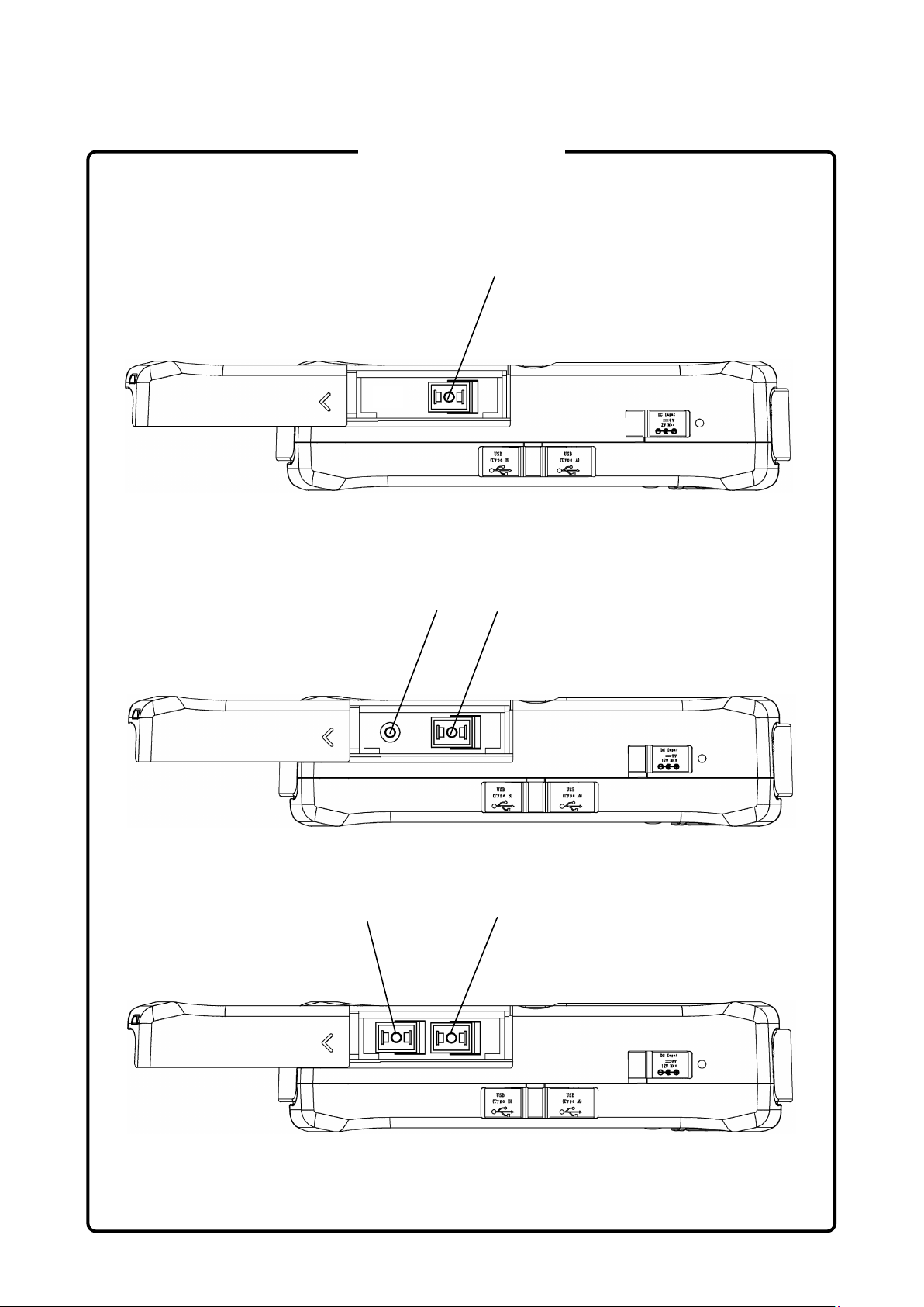
2.2.2 Top Connector Panel
The top connector panel of the unit contains the measurement port, USB
ports, DC Input port, and battery status LED.
Figure 2.2.2-1 Top Connector Panel (MU909014A/B, MU909015A6/B
and MU909015C-059/069)
Figure 2.2.2-2 Top Connector Panel (MU909014A1/B1, MU909015B1)
Figure 2.2.2-3 Top Connector Panel (MU909014C/C6, MU909015C/C6
and MU909015C6-059/069)
[1]
Slide Cover
[2]
Measurement Port
1625 nm or 1650 nm OTDR (MU909014A, MU909015A6)
1310/1550 nm OTDR (MU909014B, MU909015B)
1310/1490/1550 nm OTDR (MU909015C-059/069)
Page 53

2.2 Name of Each Part
2-9
Preparation
[3]
Measurement Port
1625 nm or 1650 nm OTDR (MU909014A1)
1310/1550 nm OTDR (MU909014B1, MU909015B1)
[4]
Visual Fault Locator Port
[5]
Measurement Port
1310/1550 nm OTDR (MU909014C/C6, MU909015C/C6)
1310/1490/1550 nm OTDR (MU909015C6-059/069)
[6]
Measurement Port
1625 nm or 1650 nm OTDR (MU909014C/C6, MU909015C/C6)
Optical power meter (MU909015C6-059/069)
[7]
USB (Type B) Port
[8]
USB (Type A) Port
[9]
DC Input port
[10]
Battery Status LED
2
Page 54

Chapter 2 Preparation
2-10
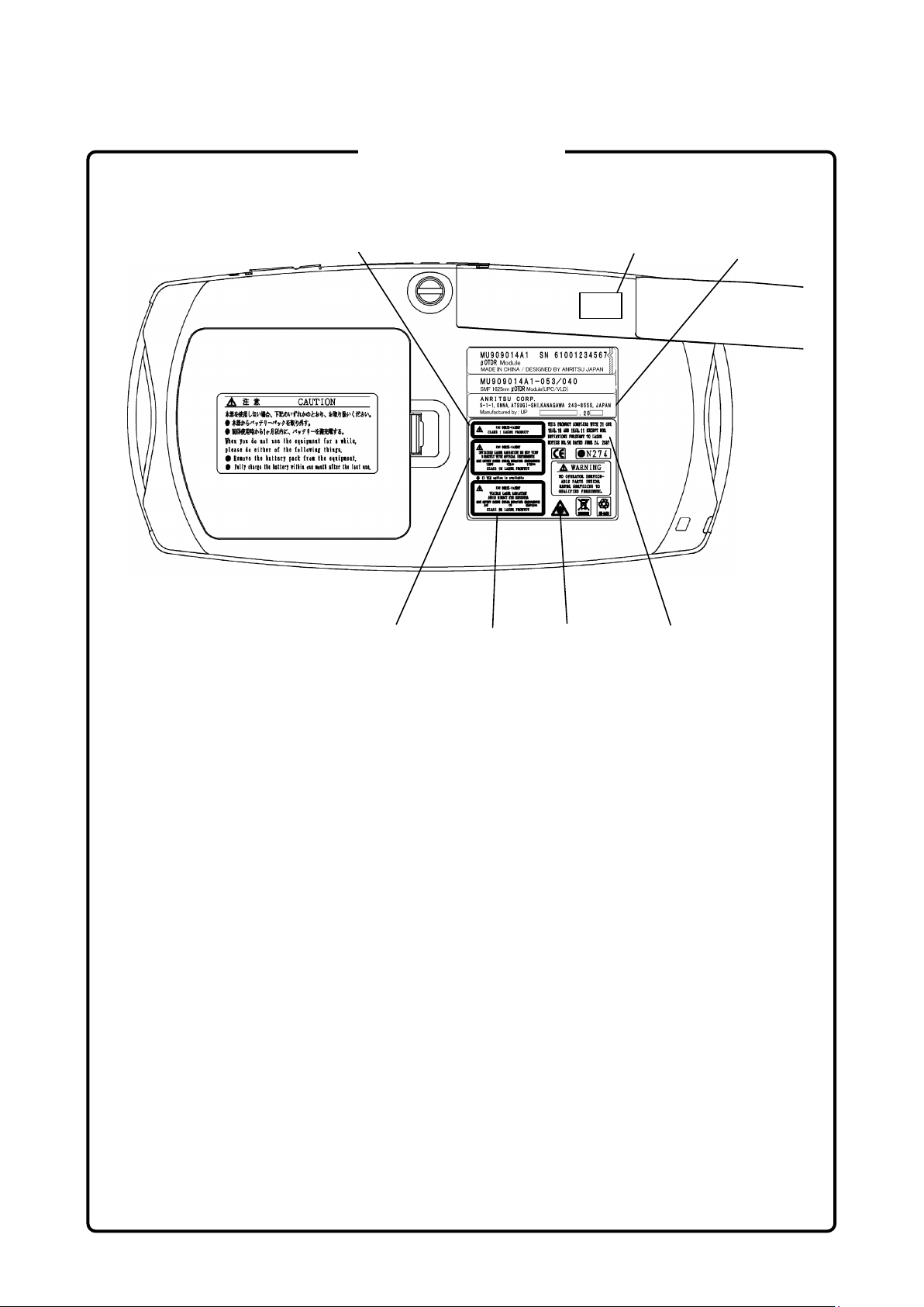
2.2.3 Back Panel
The back panel contains the battery compartment and a fastener that
secures the test module to the Network Master main unit.
There are also various compliance and warning labels as well as the
model and serial number label (item 3 in Figure 2.2.3-1).
Figure 2.2.3-1 Back Panel
[1]
Battery Compartment
[2]
Fastener
[3]
Model and serial number label
[4]
Compliance and warning labels
Page 55

2.2 Name of Each Part
2-11
Preparation
2.2.4 Bottom Panel
The bottom panel of the main frame is provided with the model and
serial number label.
Figure 2.2.4-1 Bottom Panel
[1]
Model and serial number label
①
2
Page 56

Chapter 2 Preparation
2-12
2.3 Basic Notes on Use
Keep the measurement port cover closed except when a
cable is connected. This cover prevents dust and other
contaminants from collecting on the measurement port.
Condensation may occur on the inside surface of the unit
when it is carried into a room (high temperature) from an
outdoor location (low temperature), etc. If this occurs,
allow the unit to dry out thoroughly before turning on the
power. Water droplets and dust in the MT9090A, etc., can
cause a short circuit, resulting in a fire, electric shock, or
accident.
CAUTION
Use the unit within the operating temperature range
(–10°C to +50°C) and storage temperature range (–30°C to
+70°C). If the unit is placed in a car or other enclosed
space for a long time, the ambient temperature may
exceed the specified range, resulting in a unit malfunction.
Do not use any AC charger/adapter or Ni-MH battery pack
other than the one supplied. Otherwise, the unit may be
damaged due to nonconformity with specifications.
Never look directly into the cable connector on the
equipment nor into the end of a cable connected to the
equipment. If laser radiation enters the eye, there is a
risk of injury.
In addition, the unit outputs high-power optical pulses.
Remove the communication device from the optical fiber
before measurement to prevent damage to the photo
receiving circuit of the communication device connected
to the optical fiber to be measured, Anritsu will take no
responsibility for damage to the communication or any
other device.
Anritsu recommends that the unit be inspected once a
year at Anritsu Customer Services (a fee will be charged).
Page 57

2.4 Supplying Power
2-13
Preparation
For other notes on use, read the safety-related information
in this manual thoroughly before use.
2.4 Supplying Power
Connecting AC charger/adapter
Use the AC charger/adapter provided as a standard accessory of the main
frame.
Using other AC adapters may result in damage to the unit and/or battery
pack.
CAUTION (Continued)
2
Figure 2.4-1 AC Adapter
1. Open the DC Input connector cover (Figure 2.2.2-1) and plug the AC
charger/adapter jack to the DC Input connector.
2. Plug the AC charger/adapter’s transformer into an AC outlet.
Page 58

Chapter 2 Preparation
2-14
2.5 Using Ni-MH Battery Pack
2.5.1 Installing Ni-MH Battery Pack
Follow the procedure below to install a Ni-MH battery pack.
Always power down the Network Master before removing
the Ni-MH battery pack. The battery pack and/or the unit
may be damaged when you remove the battery pack with
the Network Master powered on.
Remove the Ni-MH battery pack to avoid damage to the
battery pack and/or the unit when storing the Network
Master for a long period of time (several months).
Otherwise, be sure to recharge the unit periodically (every
one or two months).
CAUTION
1. Power down the unit if operating. Disconnect the AC
charger/adapter if connected.
2. Hold down the latch and lift the battery compartment cover (Figure
2.2.3-1) to open.
3. Remove batteries if installed.
4. Plug the battery pack connector into the battery pack plug of the
module. The battery pack connector has an alignment tab to prevent
reverse polarity connection. Align the connector tab with the plug
slot to make the correct connection.
CAUTION
Correctly plug the three-pin battery pack connector into
the battery plug. Wrong connection may damage the
battery pack and main frame.
5. Slide the Ni-MH battery pack into the battery compartment, making
sure the followings:
The battery release ribbon (red) is tucked underneath, leaving a
•
certain amount exposed to use when removing the battery pack.
The THIS SIDE UP label is facing up.
•
6. Reattach the battery compartment cover.
Page 59

2.5 Using Ni-MH Battery Pack
2-15
Preparation
2
Figure 2.5.1-1 Battery Compartment
[1]
Ni-MH battery pack plug
[2]
Module release latch
[3]
Ni-MH battery pack
[4]
Battery release ribbon (Red)
Page 60

Chapter 2 Preparation
2-16
2.5.2 Battery Replacement – Battery pack to AA batteries
MT9090A can also be powered by AA Ni-MH or alkaline batteries.
Follow the procedure below to replace the battery pack with AA batteries:
CAUTION
Always power down the unit before removing old AA
batteries. Settings and data files may be lost if the
batteries are removed with powered on.
If storing the unit for a long period of time (1 to 2 months),
remove replaceable batteries from the unit. When periods
without use in the Network Master, they may corrode or
leak and damage the main frame.
Follow the instructions in the manual when using AA
batteries.
When changing the batteries, always use new batteries of
the same type of manufacturer and change all four
batteries at a time. Wrong battery can cause the battery to
overheat or damage the Network Master.
Take care not to get burned when replacing alkaline
batteries with new ones. Temperature of alkaline batteries
may increase by approximately 20°C after 2 hours of
continuous measurement.
1. Power down the unit if operating. Disconnect the AC
charger/adapter if connected.
2. Hold the latch and lift the battery compartment cover (Figure
2.2.3-1) to open.
3. Pull the battery release ribbon to lift the Ni-MH battery pack, and
unplug it from its receptacle located next to the module release
latch.
4. Insert 4 new AA batteries into the compartment in correct directions,
referring to the polarity symbols marked next to the battery
contacts.
5. Reattach the battery compartment cover.
Page 61

2.5 Using Ni-MH Battery Pack
2-17
Preparation
Note:
The Network Master does not recharge AA Ni-MH batteries.
Recharge them using a dedicated charger for Ni-MH batteries.
2
Page 62

Chapter 2 Preparation
2-18
2.6 Connecting Fiber to Measurement Port
The measurement port is used to connect fiber for Fault Locate test
applications.
CAUTION
Never force the connector ferrule or insert it at an angle
into the adapter. Optical fibers are susceptible to loss from
microbends or other stress. Position the patch cord to
minimize mechanical strain.
Use a single mode fiber for the optical connector. If a
multi-mode fiber is used by mistake, you cannot obtain
accurate measurement values.
Connect the optical fiber cable to the port displayed on the
screen. If the optical fiber cable is connected to a wrong port,
you cannot obtain accurate measurement values.
1. Slide and open the cover (Figure 2.2.2-1) on the Measurement Port.
2. Clean the surfaces of the connector and fiber before connecting the
fiber. Refer to Section 2.7 “Cleaning optical connector and adapter”
for details.
3. Connect the fiber under test directly to the measurement port.
Figure 2.6-1 Connecting Fiber to Measurement Port
Page 63

2.7 Cleaning optical connector and adapter
2-19
Preparation
2.7 Cleaning optical connector and adapter
Cleaning the end surface of the ferrule inside the MT9090A
Use the adapter cleaner, an applicable part for the MT9090A, to clean
the ferrule inside the optical I/O connector of the MT9090A. Clean the
ferrule periodically. The following shows how to clean an optical adapter,
using an FC adapter as an example. Clean other types of optical adapters
in the same manner. When the instrument is a model with a fixed SC
connector, clean with the optical connector mounted in the module.
WARNING
Be sure to check that there is no light being emitted before
cleaning and checking the ferrule end surface.
2
CAUTION
Performance will be unsatisfactory if the MT9090A is used
with dust or dirt accumulated on the ferrule end surfaces.
The ferrule end surfaces of the connected fibers and the
MT9090A may burn if high-output lights are used with
accumulated dust or dirt. Thoroughly clean the ferrule end
surfaces of the connected fibers and the MT9090A before
measurement.
Page 64

Chapter 2 Preparation
2-20
Adapter lever
1. Lift the adapter lever until the latch is released, and then gently
pull out the adapter towards you.
Figure 2.7-1 Cleaning of end surface of ferrule inside MT9090A - 1
2. Apply an alcohol-moistened adapter cleaner to the end surface and
sides of the ferrule to clean it.
Figure 2.7-2 Cleaning of end surface of ferrule inside MT9090A - 2
3. Apply the tip of a new, dry adapter cleaner (not moistened with
alcohol) to the end surface of the ferrule and wipe in one direction a
few times.
Figure 2.7-3 Cleaning of end surface of ferrule inside MT9090A - 3
4. Clean inside the adapter using an adapter cleaner.
(Refer to the optical adapter cleaning procedure in the next page.)
5. Attach the adapter in the reverse order or removal with care not to
damage the end surface of the ferrule.
Page 65

2.7 Cleaning optical connector and adapter
2-21
Preparation
Cleaning the optical adapter
Use the adapter cleaner for the MT9090A to clean the optical adapter
used for optical fiber cable connection. The following shows how to clean
an optical adapter, using an FC adapter as an example. Clean other
types of optical adapters in the same manner.
The following method should also be used for cleaning the adapter, which
is removed before cleaning the end surface of the ferrule inside the
MT9090A.
Insert an adapter cleaner into the split sleeve of the optical adapter, and
rotate it in one direction while moving it back and forth.
2
Figure 2.7-4 Cleaning of end surface of ferrule inside MT9090A - 4
Note:
Confirm the ferrule diameter, and use a 1.25-mm or 2.5-mm
diameter dedicated adapter cleaner.
Page 66

Chapter 2 Preparation
2-22
Cleaning the ferrule end surface of optical fiber cable
Use the ferrule cleaner, an applicable part for the MT9090A, to clean the
ferrule end surface of an optical fiber cable. The following shows how to
clean the ferrule end surface, using an FC connector as an example.
Clean other types of optical connectors in the same manner.
1. Push the ferrule cleaner lever to show the cleaning face.
Figure 2.7-5 Cleaning of ferrule end surface of optical fiber - 1
2. While holding the lever in a depressed position, press the ferrule end
surface of the optical connector against the cleaning face, and slide it
in one direction.
Figure 2.7-6 Cleaning of ferrule end surface of optical fiber - 2
Notes on cleaning
- Do not use a used adapter cleaner for cleaning, only use a new one.
- Do not use a cotton swab when finishing cleaning to prevent cotton fiber
adhesion to the ferrule end surface.
- Fit caps on unused adapters.
Page 67

2.8 Cautions on Handling Optical Fiber Cables
2-23
Preparation
2.8 Cautions on Handling Optical Fiber Cables
Optical fiber cables may degrade in performance or be damaged if
handled improperly.
Note the following points when handling them.
CAUTION
Do not pull the cable when removing the connector.
Doing so may either break the optical fiber inside the cable or
strip the cable sheath from the optical connector.
CAUTION
Do not excessively bend, fold, or pinch an optical
fiber cable.
Doing so may break the optical fiber inside the cable.
Keep the bend radius of an optical fiber cable at 30 mm or
more. If the radius is less, optical fiber cable loss will increase.
2
CAUTION
Do not excessively pull on or twist an optical fiber
cable. Also, do not hang anything by using a cable.
Doing so may break the optical fiber inside the cable.
Page 68

Chapter 2 Preparation
2-24
CAUTION
Be careful not to hit the end of an optical connector
against anything hard such as the floor or a desk by
dropping the optical fiber cable.
Doing so may damage the connector end and increase
connection loss.
WARNING
Do not touch the end of a broken optical fiber cable.
The broken optical fiber may pierce the skin, causing injury.
CAUTION
Do not disassemble optical connectors.
Doing so may break the part or degrade the performance.
Page 69

2.9 Changing Optical Connector
2-25
Preparation
2.9 Changing Optical Connector
Lift the lever until the latch is released, and then pull out the optical
connector. If the module is using a fixed SC connector, the optical
connector cannot be changed.
WARNING
Never look directly into the cable connector on the
equipment nor into the end of a cable connected to the
equipment. If laser radiation enters the eye, there is a risk
of injury.
CAUTION
2
When changing the optical connector, take care not to
scratch the connector mating surfaces.
Figure 2.9-1 Changing Optical Connector
Page 70

Chapter 2 Preparation
2-26
The connector types are shown below for reference.
Figure 2.9-2 Types of Optical Connector
Page 71

2.10 Connecting Peripheral Devices
2-27
Preparation
2.10 Connecting Peripheral Devices
The unit has two USB ports to which a USB device or personal computer
(PC) can be connected. When a PC is connected via a USB cable, files
saved in the Network Master can be transferred directly to the PC. Any
PC running Windows 2000, Windows XP SP3 or Windows 7 (32 bit) can
be connected via a USB cable to the Network Master.
2
Figure 2.10-1 USB Port
Page 72

Chapter 2 Preparation
2-28
2.10.1 Type A USB Port
The Type A USB port is provided for connecting a USB memory stick,
USB Ethernet converter, USB Wi-Fi dongle or USB Bluetooth dongle.
Use USB devices conforming to USB 1.1. Not all commercially available
USB devices are compatible with this port.
Contact Anritsu for information on USB devices that can be used.
Figure 2.10.1-1 Connecting USB memory
CAUTION
Never remove the USB memory stick when reading, saving,
copying or deleting folders or files. Failure to do so may
damage files or USB memory stick itself.
The following message dialog is displayed when USB memory is
connected to the instrument.
Figure 2.10.1-2 USB Memory Detection Dialog Message
Page 73

2.10 Connecting Peripheral Devices
2-29
Preparation
2.10.2 Type B USB Port
By using a USB cable to connect the Type B USB port of the unit to a
personal computer, you can access the internal memory of the unit
directly from the PC. Any PC running Windows 2000, Windows XP SP3
or Windows 7 (32 bit) can be connected via a USB cable to the Network
Master.
The Network Master cannot be operated when connected to a PC.
Follow the procedure below to connect the Network Master and PC.
2
CAUTION
Always use the Safely Remove Hardware function of the
PC before disconnecting the USB cable that connects the
PC and instrument. Failure to do so may damage the
internal memory.
1. Close these screens before making a connection.
The PC cannot be connected while the instrument File Utility or
Settings screen is displayed.
2. Remove a USB Ethernet converter or Video Inspection Probe, if
connected.
3. Connect one end of the USB cable to the Type B USB Port on the top
of the instrument.
4. Connect the other end of the cable to a USB port on the PC.
Figure 2.10.2-1 USB Cable Connection
Page 74

Chapter 2 Preparation
2.11 Changing Test Module
Follow the procedure below to remove the current test module from the
Network Master main frame and install a new test module.
1. Power down the unit if operating.
2. Disconnect the AC charger/adapter if connected.
3. Open the battery compartment and remove the battery pack or AA
batteries if installed.
4. Loosen the mounting screws on the back of the main frame.
5. Pull forward on the Network Master main frame to separate it from
the test module, holding down the module release latch (Figure
2.5.1-1).
Note:
Avoid damage to the cables when removing the main frame
from the module since the Network Master main frame and
test module fit together snugly.
6. Install the new test module, aligning two tabs on the back side of the
Network Master main frame (the opposite end of the 100 pin
connector) to two slots on the new test module.
7. Applying firm but gentle pressure, seat the Network Master
mainframe onto the test module.
DO NOT force two sections together.
8. Tighten the mounting screws with a tightening torque of 0.5 Nm or
less.
9. Reinstall the battery pack or AA batteries if removed in step 2.
Reattach the battery compartment cover.
Mainfr am e
Tab
Module
2-30.
Slot
Figure 2.11-1 Alignment Tabs and Slots
Page 75

Chapter 3
General Operation and System Setups
This chapter describes basic operations and system settings, such as
power-on and file-related operations.
3.1
Powering Up and Down ................................................ 3-2
3.1.1 Powering Up the Unit ........................................ 3-2
3.1.2 Powering Down the Unit ................................... 3-3
3.2 Titles of Screen Parts ................................................... 3-4
3.3 Changing General Settings ........................................... 3-6
3.3.1 General ............................................................. 3-6
3.3.2 Preferences .................................................... 3-10
3.3.3 Auto Save ....................................................... 3-15
3.4 Managing Files – Mass Storage ................................. 3-18
3.4.1 Creating New Folder ....................................... 3-20
3.4.2 Deleting File or Folder .................................... 3-21
3.4.3 Copying File or Folder .................................... 3-22
3.4.4 Renaming File or Folder ................................. 3-24
3.4.5 Copying or Deleting Multiple Files or Folders 3-25
3.5 Capturing Screen Images ........................................... 3-27
3.6 Using Softkey Board ................................................... 3-28
3.7 Using Help Function ................................................... 3-30
3.8 Confirming Version Information .................................. 3-31
3.9 Setting Screen Displayed after Power-Up .................. 3-33
3
General Operation and System Setups
3-1
Page 76

Chapter 3 General Operation and System Setups
3.1 Powering Up and Down
3.1.1 Powering Up the Unit
1. Supply power to the main frame. Refer to Section 2.4 “Connecting
Power” and 2.5 “Using Battery Pack” for more details.
2. Press
The unit performs a self-test when the Anritsu splash screen is
displayed, followed by the Network Master splash screen.
3. When the self-test passes, the Top Menu is displayed.
The message Initialization Failed is displayed if the power-up
self-test fails.
Note:
If the Network Master splash screen does not appear after
powering up, the unit may have failed in initialization or self-test.
Run the unit through a power cycle (power down/power up). If the
same problem occurs again after the unit has been run through a
power cycle, it is likely the module has not been installed correctly
to the main frame. Refer to Section 2.11 “Changing Modules”, and
retry to install the module correctly. If the problem persists,
contact the Anritsu Technical Support Center or your local Anritsu
representative.
To switch the screen displayed at step 3, refer to Section 3.9 “Setting
Screen Displayed after Power-Up”.
.
3-2
CAUTION
Do not use any AC charger/adapter other than one
supplied with the Network Master. Failure to do so may
result in damage to the unit and/or the Ni-MH battery pack.
Page 77

3.1.2 Powering Down the Unit
1. Press (Menu/Power) key, and a pop-up menu appears.
3.1 Powering Up and Down
2. Use
menu. Then, press
3. The Power Down verification screen is displayed.
Highlight Yes and then press
4. Power to the main frame is cut.
Note:
You can perform a forced power down at any time by holding down
and to select the Power Down selection in the
key.
key.
key for 10 seconds.
3
General Operation and System Setups
3-3
Page 78

Chapter 3 General Operation and System Setups
3.2 Titles of Screen Parts
The titles of screen parts are shown below.
Measurement light
Screen title
Figure 3.2-1 Names of Screen Items
Screen Title
Displays the title of the current screen.
output indicator
Power status
Time
Menu
Soft key
Measurement light output
is displayed while light for performing measurement is being
output.
Time
Displays the current time in a 24 hour format (hh:mm:ss).
Power status
Indicates that the unit is connected to an external power supply.
Indicates that the unit is operating on battery power. The amount of
charge remaining in the battery is indicated in red.
Soft keys
This area presents the on-screen details for F1 through F4 keys.
Menu
Press
is available. Press
key to display the pop-up menu for the current screen, if one
key to hide the pop-up menu while it is displayed.
3-4
Page 79

Title
Figure 3.2-2 Pop-up Window Titles
Title
The titles of pop-up windows are displayed.
3.2 Titles of Screen Parts
3
General Operation and System Setups
3-5
Page 80

Chapter 3 General Operation and System Setups
3.3 Changing General Settings
3.3.1 General
The General setups consist of basic settings for the unit: Date & Time,
Language, and Auto Power Off.
1. Press
Functions pop-up menu.
2. Use
display the Setup screen.
3. Press
The Setup-General screen consists of two tabs: Basic tab and
Advanced tab.
key on the Top Menu screen to display the General
and to select Setup, and then press key to
(General) key to display the Setup-General screen.
Figure 3.3.1-1 Setup-General Screen [Basic]
3-6
4. Use
5. Use
(1) Press
(2) Use
(3) Use
(4) Repeat steps (2) and (3) until the desired date and time are
(5) Press
6. Use
3.3.1-1 “Setting Items”.
7. Use
, , , and to select the Basic tab.
and to select the Date & Time field.
key, and the Set Date And Time screen appears.
and to move the highlight to the desired selection.
and to scroll to the desired setting.
displayed on the screen.
(OK) to accept the new Date & Time setting. To
cancel, press
and to scroll to the desired setting. Refer to Table
and
to move the highlight to the desired selection.
(Cancel).
Page 81

3.3 Changing General Settings
8. Repeat steps 6 and 7 until the desired changes are made.
9. Use
10. Use
Refer to Table 3.3.1-1 “Setting Items”.
Use and to change the setting contents.
, ,
Figure 3.3.1-2 Setup-General Screen [Advanced]
and to select Screen Capture Format.
, and
to select the Advanced tab.
3
General Operation and System Setups
11. Use
Refer to Table 3.3.1-1 “Setting Items”.
Use
12. If you want to use the Login Password, use
select Login Password. Refer to Table 3.3.1-1 “Setting Items”.
13. Press
Note:
14. Use
Table 3.3.1-1 “Setting Items”.
15. Press
16. When you have finished making the desired General setting, use
and to select Use Login Password.
and to change the setting contents.
to enter the password.
Use the AC charger/adapter when entering the password.
Please keep the password carefully. If you forget the password,
you cannot login the unit.
The default of the login password is the serial number of the
module.
and to select Remote Control Password. Refer to
to enter the password.
and to
, , , and to select Apply, and press . To cancel,
select Cancel, and then press
.
3-7
Page 82

Chapter 3 General Operation and System Setups
To restore the factory default settings, select Defaults, and then
press
17. The changes are reflected.
. Refer to Appendix B “Default Value” for more details.
3-8
Page 83

3.3 Changing General Settings
Table 3.3.1-1 Setting Items
Item Function Available Options
Changes screen display colors.
Color Theme
Language
Auto Backlight off
Auto Power Off
Screen Capture
Format
Use Login Password
Login Password Change a password for login.
Remote Control
Password
We recommend Outdoor White when
using out of doors under blue sky.
Switches the language of the
on-screen characters.
The Auto Backlight Off setting turns
off the LCD screen backlight when a
set period of time passes without any
key presses.
When the time period elapses and the
backlight goes out, pressing any key
on the unit will restore the backlight.
When the modules are operating with
batteries and this setting is Off, the
backlight goes low in 1 minute
without any key presses.
The Auto Power Off function shuts
down the unit when the unit is
inactive for a set period of time.
Changes saved data format when
Print Screen is selected from Menu.
While the Use Login Password is On,
a password prompt is displayed when
the power is turned On. The unit
cannot be operated until the user logs
in with the correct password.
Change a password for Remote
Control.
Default, Outdoor White ,
Night, Orange Crush,
Lush Green
English, Japanese, Chinese(T),
Chinese(S)
Spanish(SP), Spanish(LA),
Italian, Korean, Polish,
Portuguese, Finnish, Danish,
Swedish, Russian, Dutch
Off, 30 Secs, 5 Mins, 10 Mins,
15 Mins,
20 Mins, 25 Mins, 30 Mins,
35 Mins, 40 Mins, 45 Mins,
50 Mins, 55 Mins, 60 Mins,
Off, 10 Mins, 30 Mins, 60 Mins,
90 Mins, 120 Mins
BMP, JPEG, PNG
Off, On
Up to 12 characters
The default is the last 4 digits of
the serial number of the
module.
Up to 12 characters
*1
, French, German,
3
General Operation and System Setups
*1: Some symbols in “Chinese(S)” differ from those in other languages.
For example, “$” is displayed as “\”.
3-9
Page 84

Chapter 3 General Operation and System Setups
3.3.2 Preferences
The Preferences setups can be selected only during OTDR function, Fiber
Visualizer function or DCFL function.
1. Press the
2. Press
display the Setup screen.
3. Press
The Setup screen consists of the tabs 1, 2 and 3.
4.
Use
5. Use
3.3.2-1.
key to display the General Functions pop-up menu.
and to select Setup, and then press key to
(Preferences) to display Setup-Preferences screen.
, ,
and to scroll to the desired setting. Refer to Table
, and to select the tab 1.
3-10
Figure 3.3.2-1 Setup-Preferences Screen
(In case of OTDR function)
Note:
Enable Active Fiber Check Setup is not displayed for DCFL
function.
Auto Analysis cannot be disabled for Fiber Visualizer function
and DCFL function.
6. Press
7. Repeat steps 5 and 6 until the desired changes are made.
to select the checkbox.
Page 85

3.3 Changing General Settings
8. Use , , , and to select the tab 2.
Figure 3.3.2-2 Setup-Preferences Screen 2
(In case of OTDR or DCFL function)
3
General Operation and System Setups
Note:
Event icon movement and End event for ORL are displayed
for Fiber Visualizer function.
Figure 3.3.2-3 Setup-Preferences Screen 2
(In case of Fiber Visualizer function)
9. Use
3.3.2-1.
Use
10. If you want to change the Fiber Group, use
Group, and then press
displayed.
and to scroll to the desired setting. Refer to Table
and to change the setting.
key. The Fiber Group screen is
and to scroll Fiber
3-11
Page 86

Chapter 3 General Operation and System Setups
11.
Use
select the desired fiber group. You can change Fiber Group 2 and 3
only.
12. Use
display in the IOR : BSC Setup dialog box. Then, press
and to select the type, and then use and to
Figure 3.3.2-4 Fiber Group Screen
and to select the fiber type that you want to
to check.
13. When the type is changed, press
To cancel, press
14. Repeat steps 10 and 13 until the desired changes are made.
15. Use
16. Use
3.3.2-1.
, , , and to select the tab 3.
and to scroll to the desired setting. Refer to Table
(Cancel).
Figure 3.3.2-5 Settings Screen
(Apply).
3-12
Use
17. When completed, use
then press
and to change the setting.
key.
, , , and to select Apply, and
Page 87

3.3 Changing General Settings
To cancel, select Cancel, and then press .
To restore the factory default settings, select Defaults, and then
press
18. The changes are reflected.
. Refer to Appendix B “Default Value” for more details.
3
General Operation and System Setups
3-13
Page 88

Chapter 3 General Operation and System Setups
Table 3.3.2-1 Setting Items (Preferences)
Item Function Settings
Enable Connection
Check Step
Enable Active Fiber
Check Step
Auto Analysis
Show Internal Launch
Fiber
IOR Length
Adjustment
Distance Units
Saving Format
Fiber Group
Event icon movement*
End event for ORL*
Relative measurement
Relative distance (km)
Selects whether or not to check connected fiber status at
measurement start.
Selects whether or not to check for active (live)
communications signal in connected fiber at measurement
start.
Selects whether or not to execute automatic trace analysis
at measurement end.
Note:
Auto Analysis is always enabled for Fiber Visualizer
function.
Selects whether or not to include trace display for
main-frame built-in dummy fiber at Trace View screen.
Selects whether or not to display distance range for current
cursor when setting IOR at Test Setup screen (Figure
3.3.2-6 and Figure 3.3.2-7).
Selects units for distance range displayed at Test Setup
and Trace View screens.
Selects format of file for saving measured trace.
The size of files saved in the XML and SOR&XML formats
is relatively larger than files saved in the SOR format and
such files take a longer time to complete save processing.
If you select ZIP, multiple waveform files with different
wavelengths are saved to a single file.
Selects a Fiber Type displayed at IOR:BSC Setup dialog
box.
Note:
The Fiber Group1 cannot be changed.
All Fiber types are displayed if you select.
Selects the icon movement direction by pressing the arrow
keys on Fiber Visualizer window.
Selects whether to include end event in calculation of the
total optical return loss.
Selects starting point of events. Select an event number as
a starting point (zero position).
The event positions located before the selected event are
shown in minus values.
Note:
Select Offset when setting Relative distance (km).
Sets the distance to the starting point (zero position) in m
unit.
To activate the Relative distance, select the “Offset” in
Relative measurement.
Off, On
Off, On
Off, On
Off, On
Off, On
Kilometers,
Meters,
Kilofeet,
Feet, Mile
SOR, XML,
SOR&XML,
ZIP
Fiber Group1
Group2
Group3
Left to Right,
Right to Left
INCLUDE,
OMIT
None, 0 to 5,
Offset
0.0 to
10000.0
3-14
*: Available only for Fiber Visualizer function.
Page 89

3.3 Changing General Settings
Figure 3.3.2-6 IOR:BSC Setup Screen
(IOR Length Adjustment: Off)
3
General Operation and System Setups
3.3.3 Auto Save
Figure 3.3.2-7 IOR:BSC Setup Screen
(IOR Length Adjustment: On)
1. Press key on OTDR function to display the General Functions
pop-up menu.
2. Press
display the Setup screen.
3. Press
4. Use
3.3.3-1.
and to select Setup, and then press key to
(Auto Save) to display the Setup-Auto Save screen.
and to scroll to the desired setting. Refer to Table
3-15
Page 90

Chapter 3 General Operation and System Setups
Figure 3.3.3-1 Setup- Auto Save Screen
5. Press
6. To change the saving destination of the measurement results, select
Auto Save Folder using
selection screen.
7. Select the folder to save the measurement results and press
(Setting).
8. To add a specific word string to the file name to save the
measurement results, select File Name Prefix by using
and press
9. When editing is finished, press
10. To change the sequence number for file names, select Sequence
Number using
Input screen.
11. When editing is finished, press
12. When completed, use
then press
To cancel, select Cancel, and then press
to select the checkbox.
and press to display folder
to display the Character Input screen.
(Apply).
, and press to display the Character
(Apply).
, , , and to select Apply, and
key.
.
3-16
To restore the factory default settings, select Defaults, and then
press
13. The changes are reflected.
. Refer to Appendix B “Default Value” for more details.
Page 91

3.3 Changing General Settings
Table 3.3.3-1 Setting Items (Auto Save)
Item Function Settings
Appends Sequence Number to name set at
Enable Auto File
Name
Enable Auto Save
Auto Save Device
Auto Save Folder
File Name Prefix
Sequence Number
Date Appends date and time information to file names. Off, On
Wavelength
Filename Prefix and creates file.
Both Date and Wavelength information can be
added.
Auto-saves trace file at measurement end.
Cannot save at measurement end at real-time
measurement.
Displays a device to save files when Enable Auto
Save is selected.
Set the saving destination of the measurement
results.
Specifies save file name when Enable Auto File
Name is selected.
Appends specified number to file names.
Auto-increments the sequence number by one on
save completion.
Appends measurement wavelength data to file
names.
Note:
When ZIP is selected as a format for saving
waveforms, this item is fixed to Off.
The file naming rules are as follows.
When the SOR save format is selected, the file extension is .sor.
When the XML save format is selected, the file extension is .xml.
When the SOR&XML save format is selected, the file extension is .sor
(.xml).
When the ZIP save format is selected, the file extension is .zip.
Off, On
Off, On
Internal memory or USB
memory.
Can only save to USB
memory when USB
memory stick is inserted.
Folder Name
Alphabet, Number, Symbol
21 alphanumeric
characters max.
0 to 9999
Off, On
3
General Operation and System Setups
Filename Prefix_Date_Wavelength_Sequence Number.sor
Example:
Filename Prefix auto
Date Oct/27/2011
Wavelength 1310 nm
Sequence Number 1
auto_27102011_1310nm_001.sor
3-17
Page 92

Chapter 3 General Operation and System Setups
3.4 Managing Files – Mass Storage
Files can be saved to either built-in memory or USB memory stick. When
copying either image files of screens saved to built-in memory or trace
data files to USB memory, use the file management operations.
The Mass Storage selection provides access to the following file
operations:
Creating a new folder
Deleting files/folders
Copying files/folders
Renaming files/folders
Figure 3.4-1 Mass Storage Screen
1. Press
Storage screen.
Pressing
Highlight Mass Storage using
to display the Mass Storage screen.
The Mass Storage screen cannot be displayed during measurement
or while verifying the connection.
● Connection Check screen
● Test Setup screen
● Trace Analysis screen
● Trace View screen
(Mass Storage) on the top menu to display the Mass
at any of the following screens displays the menu.
and , and then press
3-18
Page 93

3.4 Managing Files – Mass Storage
2. Pressing (Exit) when the file operation is complete closes the
Mass Storage screen.
Notes:
If there are files or folders using characters that cannot be set
at the character input screen, the file or folder name cannot be
displayed correctly. Read the name after changing it using a PC,
etc. Refer to Section 3.6 “Using Softkey Board” for characters
that can be displayed correctly by the main frame.
The Logs, Properties, and Screen Captures folders stored in the
built-in memory are system folders used by the main frame. Do
not change system folders.
3
General Operation and System Setups
3-19
Page 94

Chapter 3 General Operation and System Setups
3.4.1 Creating New Folder
1. Access the Mass Storage File Operations screen.
2. Use
3. Verify that Multi-Select is set to Off.
When Off is set, Multi-Select/Off is displayed at
Multi-Select/On is displayed, press
and to select the mass storage device; Internal or USB.
Note:
If there is no USB device connected to the unit, USB cannot
be selected.
. If
to switch to Off.
4. Use
folder is to be located, and then press
enclosed in brackets [ ].
Repeat this operation to move to a folder two levels higher or lower
than the current folder. To move to the higher level folder, select [..]
and press
Note:
5. Press
6. Use
7. A folder named newFolder is added to the current directory.
Note:
and to select the directory or folder where the new
. Folders are displayed
.
Selecting a folder containing 500 or more files will require a
few seconds to display the folder contents on the Mass
Storage screen.
(File Operations).
and to select New Folder, and then press .
If there is already a file or folder with the same name, a
number is appended after newFolder to create the file or
folder without overwriting the existing one.
For example, when newFolder already exists, newFolder1 is
created, and if newFolder1 already exists, newFolder2 is
created.
3-20
Page 95

3.4.2 Deleting File or Folder
1. Access the Mass Storage File Operations screen.
2. Use
USB.
Note:
3.4 Managing Files – Mass Storage
and to select the mass storage device to delete; Internal or
If there is no USB memory stick attached to the unit, USB
cannot be selected.
3. Verify that Multi-Select is set to Off.
When Off is set, Multi-Select/Off is displayed at
Multi-Select/On is displayed, press
4. Use
then press
Repeat this operation to move to a folder two levels higher or lower
than the current folder. To move to the higher level folder, select [..]
and press
Note:
5. Use
selected folder is displayed enclosed in brackets [ ].
6. Press
7. Use
following message appears.
and to select the directory or folder to delete, and
. Folders are displayed enclosed in brackets [ ].
.
Selecting a folder containing 500 or more files will require a
few seconds to display the folder contents on the Mass
Storage screen.
and to select the directory or folder to delete. The
(File Operations).
and to select Delete, and then press . The
to switch to Multi-Select/Off.
. If
3
General Operation and System Setups
The file/folder displayed here will be deleted.
Figure 3.4.2-1 Confirm Delete screen
8. If the displayed folder name (file name) is correct, select Ye s using
and press . To cancel, select No.
9. The selected folder or file is deleted.
3-21
Page 96

Chapter 3 General Operation and System Setups
3.4.3 Copying File or Folder
1. Access the Mass Storage File Operations screen.
2. Use
USB.
3. Verify that Multi-Select is set to Off.
When Off is set, Multi-Select/Off is displayed at
Multi-Select/On is displayed, press
and to select the mass storage device to copy; Internal or
Note:
If there is no USB device connected to the unit, USB cannot
be selected.
. If
to switch to Off.
4. Use
then press
[ ].
Repeat this operation to move to a folder two levels higher or lower
than the current folder. To move to the higher level folder, select [..]
and press
Note:
5. Use
selected folder is displayed enclosed in brackets [ ].
6. Press
7. Use
Destination window is displayed over the Mass Storage File
Operations screen.
8. Use
and to select the directory or folder to copy, and
. The selected folder is displayed enclosed in brackets
.
Selecting a folder containing 500 or more files will require a
few seconds to display the folder contents on the Mass
Storage screen.
and to select the directory or folder to copy. The
(File Operations).
and to select Copy, and then press . The
and to select the mass storage device to copy; Internal or
3-22
USB.
Note:
If there is no USB device connected to the unit, USB cannot
be selected.
Page 97

3.4 Managing Files – Mass Storage
9. Use and to select the directory or folder to copy, and
then press
10. If you select a folder or file that already exists in the copy
destination, an overwrite confirmation message appears. If it is not
displayed, proceed to step 12.
11. To overwrite a single file:
(Paste). Press (Cancel) to not perform copying.
Use
To cancel, select No, and then press
To overwrite multiple files (a file at a time):
Use
To cancel, select No.
If a overwrite process is completed or canceled, a message
confirming you to overwrite the next file appears. The
message appears until all the selected files are processed.
To cancel, select Cancel, and then press
To overwrite multiple files (all files at a time):
Use
automatically overwrite all the files.
To cancel, select Cancel, and then press
12. Confirm that the file or folder has been pasted to the desired
location.
and to select Ye s, and then press .
.
and to select Ye s, and then press to overwrite.
.
and to select All, and then press to
.
3
General Operation and System Setups
13. Press
Figure 3.4.3-1 File(s) Copied Dialog
to close the dialog and return to the Mass Storage screen.
3-23
Page 98

Chapter 3 General Operation and System Setups
3.4.4 Renaming File or Folder
1. Access the Mass Storage File Operations screen.
2. Use
USB.
3. Verify that Multi-Select is set to Off.
When Off is set, Multi-Select/Off is displayed at
Multi-Select/On is displayed, press
4. Select the location of the folder or file for the name change using
enclosed in brackets [ ].
Repeat this operation to move to a folder two levels higher or lower
than the current folder. To move to the higher level folder, select [..]
and press
and to select the directory or folder to rename; Internal or
Note:
If there is no USB memory stick connected to the unit, USB
cannot be selected.
and , and press . The selected folder is displayed
.
. If
to switch to Off.
Note:
Selecting a folder containing 500 or more files will require a
few seconds to display the folder contents on the Mass
Storage screen.
5. Use
selected folder is displayed enclosed in brackets [ ].
6. Press
7. Use
display the SoftkeyBoard screen.
(1) Use
(2) Press
(3) Repeat steps (1) and (2) to complete the file/folder name. Up to
(4) When the file/folder name is completed, press
Refer to Section 3.6 “Using Softkey Board” for details about
character input.
and to select the directory or folder to rename. The
(File Operations).
and to select Rename, and then press to
, , , and to highlight the desired letter in
the character matrix.
key to add the highlighted letter to the name field.
23 characters can be used.
(OK). To
cancel, press
(Cancel).
3-24
Page 99

3.4 Managing Files – Mass Storage
8. The selected folder or file is changed to the input name.
If a file with the same name exists, the following message appears.
If you select Ye s, the file will be overwritten.
If you select No, the file name change will not be overwritten.
Figure 3.4.4-1 Overwrite Existing File Dialog
Following message appears if same name folder exists. In this case,
the folder name will not be changed.
3
General Operation and System Setups
Figure 3.4.4-2 Cannot Rename Directory Dialog
3.4.5 Copying or Deleting Multiple Files or Folders
Follow the following below to copy or delete multiple files or folders in
one step.
Figure 3.4.5-1 Mass Storage Screen (Multi-Select/On)
3-25
Page 100

Chapter 3 General Operation and System Setups
1. Access the Mass Storage File Operations screen.
2. Use
Internal or USB.
and to select the mass storage device to copy or delete;
Note:
If there is no USB device connected to the unit, USB cannot
be selected.
3. Press
the softkey is switched to "On" and an empty checkbox is displayed
in front of each filename in the current directory or folder.
Note:
4. Use
and then press
the highlighted file. Pressing
selected folder or file is the copy/delete target. The selected folder is
displayed enclosed in brackets [ ].
To select all of the files in the current folder or all of the folders in
the current directory; press
To clear all of the files in the current folder or all of the folders in the
current directory; press
to select Unselect All, and then press
5. Press
(Multi-Select/Off), and the current setting value (red) on
When Multi-Select is set to On, you cannot access any folders
higher or lower than the current folder.
and to select the first file or folder to copy/delete,
key. A check mark appears in the checkbox for
again clears the checkbox. The
(File Operations), use and
to select Select All, and then press key.
(File Operations), use and
key.
(File Operations).
3-26
6. Use
7. Refer to Section 3.4.2 “Deleting File or Folder” or Section 3.4.3
“Copying File or Folder” for operations from hereon.
and to select Delete or Copy, and then press .
 Loading...