

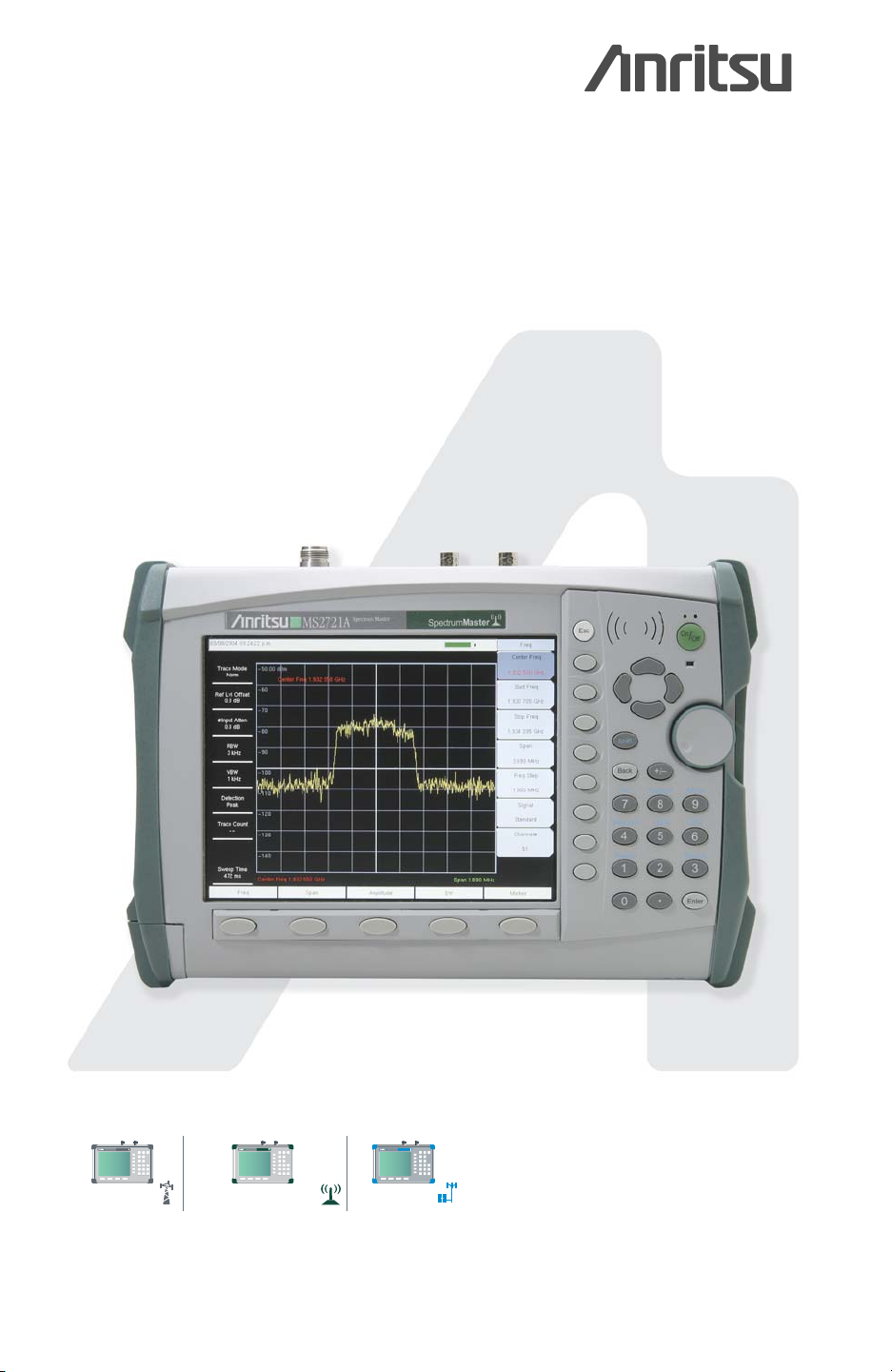
Benchtop Performance in a Handheld Spectrum Analyzer
Spectrum Master
™
MS2721A
User’s Guide
MS2712
MS2712
MS2712
SiteMaster
SpectrumMaster
CellMaster
MS2711D
Spectrum Master
S331D
Site Master
SiteMaster
SpectrumMaster
MT8212A
Cell Master
CellMaster

WARRANTY
The Anritsu product(s) listed on the title page is (are) warrante d against defects in
materials and workmanship for one year from the date of shipment.
Anritsu's obligatio n cove rs r epairin g or repl acin g produc ts which pr ove t o be defe ctive during the warranty period. Buyers shall prepay transportation charges for
equipment returned to Anritsu for warran ty r epair s. O bl igati on is l im ite d to the original purchaser. Anritsu is not liable for consequential damages.
LIMITATION OF WARRANTY
The foregoing warranty does not apply to Anritsu connectors that have failed due to
normal wear. Also, the warranty does not apply to defects resulting from impro per
or inadequate ma intenance by the Buyer, unauthorized modifica tion or misuse, or
operation outside the environmental specifications of the product. No other warranty is expressed or implied, and the remedies provided herein are the Buyer's
sole and exclusive remedies.
TRADEMARK ACKNOWLEDGMENTS
Windows, Windows 2000 and Windows XP are registered trademarks of the
Microsoft Corporation. Intel Pentium is a trademark of Intel Corporation. VxWorks is
a registered trademark, and WindML is a trademark of Wind River Systems, Inc. NI
is a trademark of National Inst ruments. Spect rum Master i s a trademark of Anritsu
Company.
NOTICE
Anritsu Company has prepared this ma nual for us e by A nritsu Company per sonnel
and customers as a guid e for the pro per in stallatio n, operati on and mai ntenan ce of
Anritsu Company equipment and computer programs. The drawings, specifications,
and information contained herein are the property of Anritsu Company, and any
unauthorized use or disclosure of these drawings, specifications, and information is
prohibited; they shall not be repr oduced, copied, or used in whole or in part as the
basis for manufacture o r sale of the equipment or software p rograms without the
prior written consent of Anritsu Company. All other trademarks contained herein are
the property of their respective owners.
UPDATES
Updates to this manual, if any, may be downloaded from the Anritsu internet site at:
http://www.us.anritsu.com.
VxWorks Runtime License
2000-1189 2000-1372
NI Device License
2000-1486
WindML Target License
Equipment marked with the Crossed-out Wheelie
Bin symbol complies with the European
Parliament and Council Directive 2002/96/EC (the
“WEEE Directive”) in the European Union.
For Products placed on the EU market after
August 13, 2005, please contact your local Anritsu
representative at the end of the product's useful
life to arrange disposal in accordance with your
initial contract and the local law.
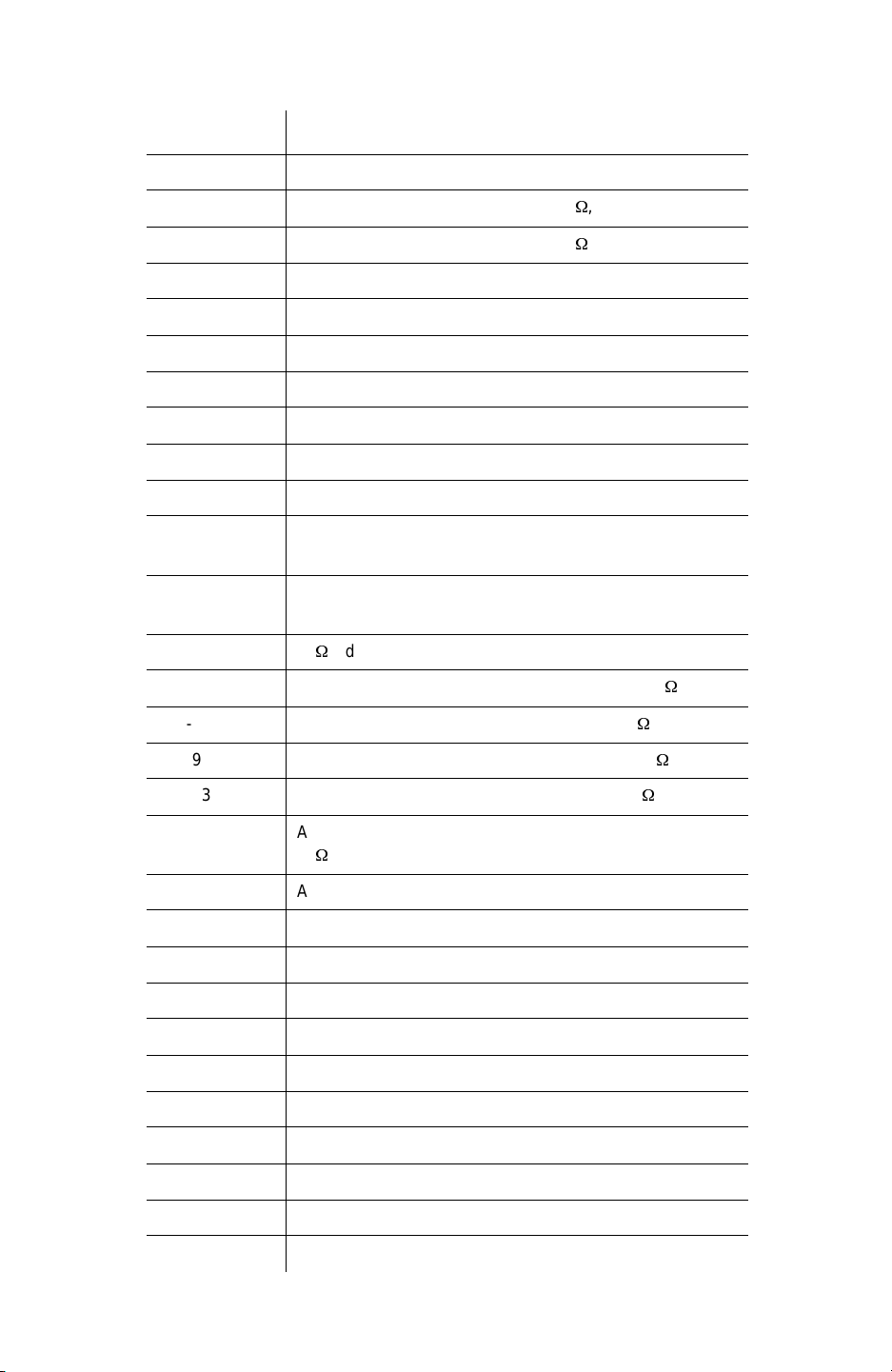
ѻકЁ᳝↦᳝ᆇ⠽䋼ܗ㋴ⱘৡ⿄ঞ䞣
᳝↦᳝ᆇ⠽䋼ܗ㋴䚼ӊৡ⿄
䪙
3E∲+J䬝&G
ࠋ㒓䏃ᵓ
3&$
ᴎǃᬃᶊ
&KDVVLV
/&' h h h h ƻ ƻ
݊Ҫ˄⬉㓚ǃ亢ǃ
䖲఼ㄝ˅
$SSHQGHGJRRGV
ƻ˖㸼⼎䆹᳝↦᳝ᆇ⠽䋼䆹䚼ӊ᠔᳝ഛ䋼ᴤ᭭Ёⱘ䞣ഛ 6-7 ޚ㾘
ᅮⱘ䰤䞣㽕∖ҹϟDŽ
h˖㸼⼎䆹᳝↦᳝ᆇ⠽䋼㟇ᇥ䆹䚼ӊⱘᶤϔഛ䋼ᴤ᭭Ёⱘ䞣䍙ߎ 6-7
ޚ㾘ᅮⱘ䰤䞣㽕∖DŽ
h
h
h ƻ h h ƻ ƻ
h h ƻ ƻ
ƻ
ƻ h h ƻ ƻ
For Chinese Customers Only YLYB
݁Ӌ䫀
>&UĎ@
⒈㘨㣃
3%%
⒈Ѡ㣃䝮
3%'(
⦃ֱՓ⫼ᳳ䰤
䖭Ͼ䆄ᰃḍ ݀ᏗⱘNj⬉ᄤֵᙃѻક∵ᶧࠊㅵ⧚ࡲ⊩njҹঞ
6-7Nj⬉ᄤֵᙃѻક∵ᶧࠊ䆚㽕∖njⱘ㾘ᅮˈ䗖⫼ѢЁ
䫔ଂⱘ⬉ᄤֵᙃѻકⱘ⦃ֱՓ⫼ᳳ䰤DŽҙ䰤Ѣ䙉ᅜ䆹ѻકⱘᅝܼ㾘㣗ঞՓ⫼
⊼ᛣџ乍ⱘ⸔ϞˈҢ⫳ѻ᮹䍋ㅫⱘ䆹ᑈ䰤ݙˈϡӮѻક᠔᳝ᆇ⠽䋼ⱘ⊘
ⓣさথᗻবᓖˈ㗠ᇍ⦃๗∵ᶧˈҎ䑿ঞ䋶ѻѻ⫳⏅ࠏഄᕅડDŽ
⊼˅⬉∴ⱘ⦃ֱՓ⫼ᳳ䰤ᰃ ᑈDŽ⫳ѻ᮹ᳳѢѻકᑣোⱘࠡಯⷕ
བ 61;;;;
Ў
ᑈ ⫳ѻDŽ


Table of Contents
Chapter 1 - General Information
Introduction. . . . . . . . . . . . . . . . . . . . . . . . . . . . . . . . . . . . . . . . . . . . 1-1
Description . . . . . . . . . . . . . . . . . . . . . . . . . . . . . . . . . . . . . . . . . . . . 1-1
Performance Specifications . . . . . . . . . . . . . . . . . . . . . . . . . . . . . . . 1-5
Preventive Maintenance . . . . . . . . . . . . . . . . . . . . . . . . . . . . . . . . . . 1-9
Calibration Requirements . . . . . . . . . . . . . . . . . . . . . . . . . . . . . . . . . 1-9
ESD Cautions . . . . . . . . . . . . . . . . . . . . . . . . . . . . . . . . . . . . . . . . . . 1-9
Battery Replacement. . . . . . . . . . . . . . . . . . . . . . . . . . . . . . . . . . . . 1-10
Soft Carrying Case . . . . . . . . . . . . . . . . . . . . . . . . . . . . . . . . . . . . . 1-11
Tilt Bail Stand Installation . . . . . . . . . . . . . . . . . . . . . . . . . . . . . . . 1-13
Anritsu Service Centers . . . . . . . . . . . . . . . . . . . . . . . . . . . . . . . . . 1-14
Chapter 2 - Quick Start Guide
Introduction. . . . . . . . . . . . . . . . . . . . . . . . . . . . . . . . . . . . . . . . . . . . 2-1
Turning the MS2721A On for the First Time. . . . . . . . . . . . . . . . . . 2-1
Front Panel Overview. . . . . . . . . . . . . . . . . . . . . . . . . . . . . . . . . . . . 2-2
Display Overview . . . . . . . . . . . . . . . . . . . . . . . . . . . . . . . . . . . . . . . 2-3
Test Panel Connectors . . . . . . . . . . . . . . . . . . . . . . . . . . . . . . . . . . . 2-4
Symbols and Indicators. . . . . . . . . . . . . . . . . . . . . . . . . . . . . . . . . . . 2-8
Self Test . . . . . . . . . . . . . . . . . . . . . . . . . . . . . . . . . . . . . . . . . . . . . . 2-9
Making Spectrum Analyzer Measurements . . . . . . . . . . . . . . . . . . 2-10
Chapter 3 - Key Functions
Introduction. . . . . . . . . . . . . . . . . . . . . . . . . . . . . . . . . . . . . . . . . . . . 3-1
Amplitude . . . . . . . . . . . . . . . . . . . . . . . . . . . . . . . . . . . . . . . . . . . . . 3-1
BW (Bandwidth). . . . . . . . . . . . . . . . . . . . . . . . . . . . . . . . . . . . . . . . 3-4
File . . . . . . . . . . . . . . . . . . . . . . . . . . . . . . . . . . . . . . . . . . . . . . . . . . 3-5
Freq (Frequency). . . . . . . . . . . . . . . . . . . . . . . . . . . . . . . . . . . . . . . . 3-8
Limit . . . . . . . . . . . . . . . . . . . . . . . . . . . . . . . . . . . . . . . . . . . . . . . . 3-10
Marker. . . . . . . . . . . . . . . . . . . . . . . . . . . . . . . . . . . . . . . . . . . . . . . 3-12
Measure. . . . . . . . . . . . . . . . . . . . . . . . . . . . . . . . . . . . . . . . . . . . . . 3-15
Mode. . . . . . . . . . . . . . . . . . . . . . . . . . . . . . . . . . . . . . . . . . . . . . . . 3-19
Preset. . . . . . . . . . . . . . . . . . . . . . . . . . . . . . . . . . . . . . . . . . . . . . . . 3-19
Span . . . . . . . . . . . . . . . . . . . . . . . . . . . . . . . . . . . . . . . . . . . . . . . . 3-20
Sweep . . . . . . . . . . . . . . . . . . . . . . . . . . . . . . . . . . . . . . . . . . . . . . . 3-21
System. . . . . . . . . . . . . . . . . . . . . . . . . . . . . . . . . . . . . . . . . . . . . . . 3-24
Trace . . . . . . . . . . . . . . . . . . . . . . . . . . . . . . . . . . . . . . . . . . . . . . . . 3-27
March 2007 10580-00103
Copyright 2004-2007 Anritsu Company Revision: J
i

Chapter 4 - Measurement Fundamentals
Introduction. . . . . . . . . . . . . . . . . . . . . . . . . . . . . . . . . . . . . . . . . . . . 4-1
Resolution Bandwidth. . . . . . . . . . . . . . . . . . . . . . . . . . . . . . . . . . . . 4-1
Video Bandwidth . . . . . . . . . . . . . . . . . . . . . . . . . . . . . . . . . . . . . . . 4-1
Sweep Limitations . . . . . . . . . . . . . . . . . . . . . . . . . . . . . . . . . . . . . . 4-2
Attenuator Functions. . . . . . . . . . . . . . . . . . . . . . . . . . . . . . . . . . . . . 4-2
Preamplifier Operation . . . . . . . . . . . . . . . . . . . . . . . . . . . . . . . . . . . 4-3
Chapter 5 - Field Measurements
Introduction. . . . . . . . . . . . . . . . . . . . . . . . . . . . . . . . . . . . . . . . . . . . 5-1
Occupied Bandwidth Measurement . . . . . . . . . . . . . . . . . . . . . . . . . 5-1
Channel Power Measurement. . . . . . . . . . . . . . . . . . . . . . . . . . . . . . 5-2
CDMA Channel Power. . . . . . . . . . . . . . . . . . . . . . . . . . . . . . . . . . . 5-2
CDMA Channel Power Measurement . . . . . . . . . . . . . . . . . . . . . . . 5-3
GSM Channel Power Measurement . . . . . . . . . . . . . . . . . . . . . . . . . 5-3
AMPS Channel Power Measurement . . . . . . . . . . . . . . . . . . . . . . . . 5-4
Adjacent Channel Power Ratio. . . . . . . . . . . . . . . . . . . . . . . . . . . . . 5-5
Adjacent Channel Power Measurement . . . . . . . . . . . . . . . . . . . . . . 5-5
GSM Adjacent Channel Power Measurement . . . . . . . . . . . . . . . . . 5-6
AMPS (TDMA) Adjacent Channel Power Measurement . . . . . . . . 5-7
Out-of-Band Spurious Emission Measurement . . . . . . . . . . . . . . . . 5-8
In-band/Out-of-Channel Measurements . . . . . . . . . . . . . . . . . . . . . 5-10
In-band Spurious Measurement . . . . . . . . . . . . . . . . . . . . . . . . . . . 5-10
Field Strength . . . . . . . . . . . . . . . . . . . . . . . . . . . . . . . . . . . . . . . . . 5-12
AM/FM/SSB Demodulation. . . . . . . . . . . . . . . . . . . . . . . . . . . . . . 5-13
Carrier to Interference Ratio Measurement . . . . . . . . . . . . . . . . . . 5-13
Chapter 6 - Interference Analysis Measurements
Introduction. . . . . . . . . . . . . . . . . . . . . . . . . . . . . . . . . . . . . . . . . . . . 6-1
Freq Menu. . . . . . . . . . . . . . . . . . . . . . . . . . . . . . . . . . . . . . . . . . . . . 6-1
Amplitude Menu. . . . . . . . . . . . . . . . . . . . . . . . . . . . . . . . . . . . . . . . 6-3
BW (Bandwidth) Menu . . . . . . . . . . . . . . . . . . . . . . . . . . . . . . . . . . 6-5
Measurements Menu. . . . . . . . . . . . . . . . . . . . . . . . . . . . . . . . . . . . . 6-6
Spectrum Menu. . . . . . . . . . . . . . . . . . . . . . . . . . . . . . . . . . . . . . . . . 6-7
Spectrogram Menu . . . . . . . . . . . . . . . . . . . . . . . . . . . . . . . . . . . . . 6-11
Signal Strength Menu . . . . . . . . . . . . . . . . . . . . . . . . . . . . . . . . . . . 6-12
RSSI (Received Signal Strength Indicator) Menu . . . . . . . . . . . . . 6-13
Marker Menu . . . . . . . . . . . . . . . . . . . . . . . . . . . . . . . . . . . . . . . . . 6-14
Spectrogram Procedure. . . . . . . . . . . . . . . . . . . . . . . . . . . . . . . . . . 6-17
Signal Strength . . . . . . . . . . . . . . . . . . . . . . . . . . . . . . . . . . . . . . . . 6-19
RSSI Procedure. . . . . . . . . . . . . . . . . . . . . . . . . . . . . . . . . . . . . . . . 6-20
Chapter 7 - Channel Scanner Measurements
Introduction. . . . . . . . . . . . . . . . . . . . . . . . . . . . . . . . . . . . . . . . . . . . 7-1
Scanner: . . . . . . . . . . . . . . . . . . . . . . . . . . . . . . . . . . . . . . . . . . . . . . 7-1
Amplitude . . . . . . . . . . . . . . . . . . . . . . . . . . . . . . . . . . . . . . . . . . . . . 7-3
ii

Custom Setup . . . . . . . . . . . . . . . . . . . . . . . . . . . . . . . . . . . . . . . . . . 7-3
Measurements. . . . . . . . . . . . . . . . . . . . . . . . . . . . . . . . . . . . . . . . . . 7-4
Sample Procedure . . . . . . . . . . . . . . . . . . . . . . . . . . . . . . . . . . . . . . . 7-6
Custom Setup . . . . . . . . . . . . . . . . . . . . . . . . . . . . . . . . . . . . . . . . . . 7-6
Chapter 8 - Master Software Tools
Introduction. . . . . . . . . . . . . . . . . . . . . . . . . . . . . . . . . . . . . . . . . . . . 8-1
Features. . . . . . . . . . . . . . . . . . . . . . . . . . . . . . . . . . . . . . . . . . . . . . . 8-1
System Requirements . . . . . . . . . . . . . . . . . . . . . . . . . . . . . . . . . . . . 8-1
Installation . . . . . . . . . . . . . . . . . . . . . . . . . . . . . . . . . . . . . . . . . . . . 8-2
Connection . . . . . . . . . . . . . . . . . . . . . . . . . . . . . . . . . . . . . . . . . . . . 8-2
Using Master Software Tools . . . . . . . . . . . . . . . . . . . . . . . . . . . . . . 8-4
Language Editor . . . . . . . . . . . . . . . . . . . . . . . . . . . . . . . . . . . . . . . 8-12
Signal Standards Editor . . . . . . . . . . . . . . . . . . . . . . . . . . . . . . . . . 8-14
Appendix A - Signal Standards
Introduction. . . . . . . . . . . . . . . . . . . . . . . . . . . . . . . . . . . . . . . . . . . . 6-1
Appendix B - Error Messages
Introduction. . . . . . . . . . . . . . . . . . . . . . . . . . . . . . . . . . . . . . . . . . . . 6-1
Self Test or Application Self Test Errors . . . . . . . . . . . . . . . . . . . . . 6-1
Operation Errors . . . . . . . . . . . . . . . . . . . . . . . . . . . . . . . . . . . . . . . . 6-2
Interference Analyzer Messages . . . . . . . . . . . . . . . . . . . . . . . . . . . 6-7
Channel Scanner Messages. . . . . . . . . . . . . . . . . . . . . . . . . . . . . . . . 6-9
Index
iii

iv

Chapter 1 General Information
Introduction
This chapter provides a description, performance specifications, optional accessories, preventive maintenance, and calibration requirements for the Anritsu Handheld Spectrum Analyzer model listed below. Throughout this manual, this instrument may be referred to as a
Spectrum Master.
Model Frequency Range
MS2721A 100 kHz to 7.1 GHz
Description
Spectrum Master is a synthesizer-bas ed hand held spectrum analyzer that pro vides quick and
accurate measurement results. Measurements can be easily made by using the main instrument functions: frequency, span, amplitude and bandwidth. Dedicated keys for common
functions and a familiar calculator-type keypad are available for fast data entry.
Time and date stamping of measurement data is automatic. The internal memory provides
for the storage and recall of more than 1000 measurement setups and more than 1000 traces.
The bright daylight-viewable, high-resolution color liquid crystal display (LCD) provides
easy viewing in a variety of lighting conditions. Spectrum Master is capable of up to three
hours of continuous operation from a fully charged battery and can be operated from a 12
VDC source, which also simultaneously charges the battery.
Spectrum Master is designed for mo nitoring, measuri ng, and analyzing signal enviro nments.
Typical measurements include: in-band interference, transmit spectrum analysis, plus cell
site and 802.11a/b/g interference testing. A full range of marker capabilities such as peak,
center and delta functions are pro vided for fast er, more comprehensive analysi s of disp layed
signals. Upper and lower multi-segmented limit lines are available to create quick, simple
pass/fail measurements. A menu option provides for an audible alert when the limit value is
exceeded.
Anritsu Master Software Tools, a PC-based software program, provides for s toring measurement data. Master Software Tools can also convert the Spectrum Master display into several
graphic formats.
Measurements may be stored in either internal memory or the external Compact Flash.
Stored measurements can be downloaded to a PC using the included USB and Ethernet
cables. Once stored, the measurement can then be displayed, scaled, or enhanced with markers and limit lines. Historical graphs can be overlaid with current data using the PC mouse in
a drag-and-drop fashion. The underlying data can be extracted and used in spreadsheets or
for other analytical tasks.
1-1

Accessories
The following standard accessories are supplied with the MS2721A:
Part Number Description
10580-00103 MS2721A User's Guide
61382 MS2721A Soft Carrying Case
2300-498 Master Software Tools Program CD ROM
633-44 MS2721A Rechargeable Li-Ion Battery
40-168 MS2721A AC-DC Adapter
806-141 MS2721A Automotive Cigarette Lighter 12 Volt DC Adapter
2000-1360 USB A/5-pin mini-B Cable
2000-1371 Ethernet Cable, 7 feet (213 cm)
1091-27 Type-N male to SMA female Adapter
1091-172 Type-N male to BNC female Adapter
2000-1358 64 MB Compact Flash Memory Module
64343 Tilt Bail Stand
One year Warranty (includes battery, firmware, and software)
CAUTION
When using the Automotive Cigarette Lighter 12 VDC Adapter, Anritsu Part Number
806-141, always verify that the sup ply i s rated fo r a mini mum of 60 Watts @ 12 VDC,
and that the socket is clear of any dirt or debris. If the adapter plug becomes hot to the
touch during operation, discontinue use immediately.
1-2
The following optional accessories are available for the MS2721A:
Part Number Description
42N50A-30 30 dB, 50W, Bi-dir., DC-18 GHz, N(m) to N(f) Attenuator
34NN50A Precision Adapter, DC to 18 GHz, 50Ω, N(m) to N(m)
34NFNF50C Precision Adapter, DC to 18 GHz, 50Ω, N(f) to N(f)
15NNF50-1.5B Test port cable arm ore d, 1 .5 m et er, N(m) to N(f), 18.0 GHz
15NN50-1.5C Test port cable armored, 1.5 meter, N(m) to N(m), 6 GHz
15NN50-3.0C Test port cable armored, 3.0 meter, N(m) to N(m), 6 GHz
15NN50-5.0C Test port cable armored, 5.0 meter, N(m) to N(m), 6 GHz
15NNF50-1.5C Test port cable armored, 1.5 meter, N(m) to N(f), 6 GHz
15NNF50-3.0C Test port cable armored, 3.0 meter, N(m) to N(f), 6 GHz
15NNF50-5.0C Test port cable armored, 5.0 meter, N(m) to N(f), 6 GHz
15ND50-1.5C Test port cable armored, 1.5 meter, N(m) to 7/16 DIN(m),
6.0 GHz
15NDF50-1.5C Test port cable armored, 1.5 meter, N(m) to 7/16 DIN(f),
6.0 GHz
12N50-75B 75Ω Adapter, 7.5 dB loss
510-90 Adapter, 7/16 DIN (f) to N(m), DC to 7.5 GHz, 50
510-91 Adapter, 7/16 DIN (f)-N(f), DC to 7.5 GHz, 50
510-92 Adapter, 7/16 DIN (m)-N(m), DC to 7.5 GHz, 50
510-93 Adapter, 7/16 DIN(m)-N(f), DC to 7.5 GHz, 50
510-96 Adapter 7/16 DIN (m) to 7/16 DIN (m), DC to 7.5 GHz,
50
Ω
510-97 Adapter 7/16 DIN (f) to 7/16 DIN (f), 7.5 GHz
61382 Spare Soft Carrying Case
40-168 Spare AC/DC Adapter
806-141 Spare Automotive Cigarette Lighter 12 Volt DC Adapter
760-235 MS2721A Transit Case
2300-498 Master Software Tools Program CD ROM
10580-00103 Anritsu User’s Guide, Model MS2721A (spare)
10580-00104 Anritsu Programming Manual, Model MS2721A
10580-00105 Anritsu Maintenance Manual, Model MS2721A
Ω
Ω
Ω
Ω
633-44 Rechargeable battery, Li-Ion
2000-1374 Dual Battery charger, Li-Ion with universal power supply
1-3

Part Number Description
2000-1030 Portable antenna, 50Ω, SMA (m) 1.71-1.88 GHz
2000-1031 Portable antenna, 50Ω, SMA (m) 1.85-1.99 GHz
2000-1032 Portable antenna, 50Ω, SMA (m) 2.4-2.5 GHz
2000-1035 Portable antenna, 50Ω, SMA (m) 896-941 MHz
2000-1200 Portable antenna, 50Ω, SMA (m) 806-869 MHz
2000-1361 Portable Antenna, 50Ω, SMA (m) 5725-5825 MHz
2000-1358 64 MB Compact Flash Memory Module
2000-1411 Portable Yagi Antenna, 10 dBd, N(f), 822 to 900 MHz
2000-1412 Portable Yagi antenna, 10 dBd, N(f), 885 to 975 MHz
2000-1413 Portable Yagi antenna, 10 dBd, N(f), 1.71 to 1.88 GHz
2000-1414 Portable Yagi antenna, 9.3 dBd, N(f), 1.85 to 1.99 GHz
2000-1415 Portable Yagi antenna, 10 dBd, N(f), 2.4 to 2.5 GHz
2000-1416 Portable Yagi antenna, 10 dBd, N(f), 1.92 to 2.23 GHz
1-4

Performance Specifications
Frequency
Frequency Range: 100 kHz to 7.1 GHz
Tuning Range: 9 kHz to 7.1 GHz
Tuning Resolution: 1 Hz
Frequency Referenc e: Aging: ±1 ppm/yr.
Accuracy: ±1 ppm (25°C ± 25°C) + long term drift
Frequency Span: 10 Hz to 7.1 GHz plus 0 Hz (zero span)
Span Accuracy: Same as frequency reference accuracy
Sweep Time: Minimum 100 ms swept, 10 µs in zero span
Sweep Time Accuracy: ± 2% in zero span
Sweep Trigger: Free run, Single, Video, External
Resolution Bandwidth: (-3 dB width) 10 Hz to 3 MHz in 1-3 sequence ± 10%, 8 MHz
demodulation bandwidth. When the quasi-peak detector is
selected, available resolution bandwidths are 220 Hz, 9 kHz
and 120 kHz to meet CISPR requirements.
Video Bandwidth: (-3 dB) 1 Hz to 3 MHz in 1-3 sequence
When the quasi-peak detector is selected, the available video
bandwidths are 220 Hz, 9 kHz and 120 kHz to meet CISPR
requirements.
SSB Phase Noise: -100 dBc/Hz max at 10, 20 and 30 kHz offset from carrier.
-102 dBc/Hz max at 100 kHz offset from carrier.
Amplitude
Measurement Range: DANL to +30 dBm
Absolute Amplitude Accuracy:
≥
Power levels:
-50 dBm, <35 dB input attenuation
100 kHz to 10 MHz ±1.5 dB
>10 MHz to 4 GHz ±1.25 dB
>4 to 7.1 GHz ±1.75 dB
40 to 55 dB input attenuation
100 kHz to 10 MHz ±1.5 dB
>10 MHz to 4 GHz ±1.75 dB
>4 to 6.5 GHz ±1.75 dB
>6.5 to 7.1 GHz ±2 dB
60 to 65 dB input attenuation
100 kHz to 10 MHz ±1.5 dB
>10 MHz to 6.5 GHz ±1.75 dB
>6.5 to 7.1 GHz ±3 dB
Preamplifier on, 0 or 10 dB input attenuation
100 kHz to 4 GHz ±1.5 dB
>4 to 7.1 GHz ±1.75 dB
Second Harmonic Distortion (0 dB input attenuation, -30 dBm input):
-50 dBc, 0.05 to 0.75 GHz
1-5

-40 dBc, >0.75 to 1.05 GHz
-50 dBc, >1.05 to 1.4 GHz
-70 dBc, >1.4 to 2 GHz
-80 dBc, >2 GHz
Third Order Intercept (TOI) (preamplifier off)
Frequency Typical
50 MHz to 300 MHz >8 dBm
>300 MHz to 2.2 GHz >10 dBm
>2.2 to 2.8 GHz >15 dBm
>2.8 to 4.0 GHz >10 dBm
>4.0 to 7.1 GHz >13 dBm
0 dB attenuation, -20 dBm reference level, -20 dBm tones, spaced 100 kHz
Displayed Average Noise Level: DANL in 10 Hz RBW
Frequency Preamplifier On Preamplifier Off
Typical Max Typical Max
>10 MHz to 1 GHz -153 -151 -130 -127
>1 GHz to 2.2 GHz -150 -149 -126 -123
>2.2 to 2.8 GHz -146 -143 -120 -116
>2.8 to 4.0 GHz -150 -149 -129 -126
>4.0 to 7.1 GHz -148 -144 -121 -117
Test conditions: Input attenuation: 0 dB, RMS detection, Reference level = -20 dBm for
preamplifier off and -50 dBm for preamplifier on.
NOTE: Discrete spurious signals are not included in the measurement of
DANL as they are covered by the residual spurious specification.
Noise Figure (derived from DANL measurement) 0 dB attenuation, 23°C: Preamp On
Frequency Typical
>10 MHz to 1 GHz 11 dB
>1 GHz to 2.2 GHz 14 dB
>2.2 to 2.8 GHz 18 dB
>2.8 to 4.0 GHz 14 dB
>4.0 to 7.1 GHz 16 dB
Display Range: 1 to 15 dB/div in 1dB steps. Ten divisions displayed.
Amplitude Units:
Log Scale Modes: dBm, dBV, dBmv, dBµV,
Linear Scale Modes: nV, µV, mV, V, kV, nW, µW, mW, W, kW
Attenuator Range: 0 to 65 dB
Attenuator Resolution: 5 dB steps
Input-Related Spurious: -60 dBc max*, (<-70 dBc typical), -30 dBm input, 0 dB RF
attenuation
*Exceptions:
Input Frequency Spur Level
1674 MHz -46 dBc max (-56 dBc typical), 0 to 2800 MHz
>1674 to 1774 MHz -50 dBc max (-60 dBc typical) at (F input -1674 MHz)
1-6

Residual Spurious, preamplifier off: (RF input terminated, 0 dB RF attenuation)
-90 dBm max**, 100 kHz to <3200 MHz
-84 dBm max**, 3200 to 7100 MHz
**Exceptions:
Frequency Spur Level
250, 300, and 350 MHz -85 dBm max
~4010 MHz -80 dBm max (-90 dBm typical)
~5084 MHz -70 dBm max (-83 dBm typical)
~5894 MHz -75 dBm max (-87 dBm typical)
~7028 MHz -80 dBm max (-92 dBm typical)
Residual Spurious, preamplifier on: -100 dBm max
(RF input terminated, 0 dB RF attenuation)
General
RF Input VSWR: 2.0:1 maximum, 1.5:1 typical (≥10 dB attenuation)
Max Continuous Input: (
Input Damage Level*:
≥
10 dB attenuation, >+43 dBm, ±50 VDC
<10 dB attenuation, >+23 dBm, ±50 VDC
* Input protection relay opens at >+30 dBm with 10 dB input attenuation and at approxi-
mately +10 to +23 dBm with <10 dB attenuation
≥
10 dB attenuation), +30 dBm
ESD Damage Level: >10 kV 10 dB attenuation
Ext. Ref. Frequencies: 1, 1.2288, 1.544, 2.048, 2.4576, 4.8, 4.9152, 5, 9.8304, 10,
13 and 19.6608 MHz at -10 to +10 dBm
Display:
Bright daylight-viewable color transmissive LCD, Full SVGA, 8.4"
Languages:
Built-in English, Spanish, Italian, French, German, Japanese, Korean, and Chinese. The
instrument also has the capability to have two customized languages installed from Master Software Tools.
Marker Modes:
6 Markers, 9 Modes: Normal, Delta, Marker to Peak, Marker to Center, Marker to Reference Level, Next Peak Left, Next Peak Right, All Markers Off, Noise Marker, Frequency
Counter Marker (1 Hz resolution), Marker to Channel, Marker 1 Reference, Fixed or
Tracking Markers.
Sweeps:
Full span, Zero span, Span Up/Span Down in 1-2-5 increments
Detection:
Peak, Negative, Sample, RMS, Quasi-Peak
1-7

Memory:
The internal memory provides for the storage and recall of more than 1000 measure-
ment setups and more than 1000 traces.The contents of the internal memory can be
copied to and from a removable Compact Flash card. The removable compact flash card
can be any size, although it must be a minimum of 64 MB to be able to hold the entire
contents of the internal flash memory. Measurements may be stored directly to a Compact Flash memory module.
Traces:
Displayed Traces: Three Traces with trace overlay. One trace is always the live data; two
traces can be either stored data or traces which have been mathematically manipulated.
All three traces can show recalled measurements. Trace A can show normal live data,
Max Hold, Min Hold, or the average of multiple measurements. Trace B can hold a
stored measurement that can originate from either Trace A or C. Trace C can be set to
be Max Hold, Min Hold, a stored measurement originating either from Trace A or Trace
C, or a trace math measurement that can be either A-B or B-A.
Interfaces:
Type N female RF connector
BNC female connectors for external reference and external trigger
5-pin Mini-B USB 2.0 for data transfer to a PC
RJ45 connector for Ethernet 10/100 Base-T
2.5 mm 3-wire headset connector (standard, non-Nokia, cellular telephone headset)
Size & Weight:
Size: 12 x 8 x 3 inches (305 x 203 x 76 mm)
Weight: < 6.9 pounds (3.1 kg) typical
Environmental:
MIL-PRF-28800F class 2
Operating: -10º C to 55º C, humidity 85% or less
Storage: -51º C to 71º C
Altitude: 4600 meters, operating and non-operating
Safety:
Conforms to EN 61010-1 for Class 1 portable equipment
Electromagnetic Compatibility:
Meets European Community requirements for CE marking.
1-8

Preventive Maintenance
Spectrum Master preventive maintenance consists of cleaning the unit and inspecting and
cleaning the RF connector on the instrument and all accessories. Clean the Spectrum Master
with a soft, lint-free cloth dampened with water or water and a mild cleaning solution.
CAUTION: To avoid damaging the display or case, do not use solvent s or abrasi ve cleaners .
Clean the RF connectors and center pins with a cotton swab dampened with denatured alco-
hol. Visually inspect the connectors. The fingers of N(f) connectors and the pins of N(m)
connectors should be unbroken and uniform in appearance. If you are unsure whether the
connectors are good, gauge the connectors to confirm that their dimensions are correct.
Visually inspect the test port cable(s). The test port cable should be uniform in appearance,
not stretched, kinked, dented, or broken.
Calibration Requirements
The Spectrum Master loads factory calibration data during start-up , eliminating the n eed fo r
daily calibration checks.
Although Spectrum Master does not require daily field calibration, Anritsu recommends
annual calibration and performance verification by local Anritsu serv ice centers. Anritsu service centers are listed in this chapter.
ESD Cautions
The MS2721A, like other high performance instruments, is susceptible to ESD damage.
Very often, coaxial cables an d antennas build up a static charge, which, if allowed to discharge by connecting directly to the MS2721A without discharging the static charge, may
damage the MS2721A input circuitry. MS2721A operators should be aware of the potential
for ESD damage and take all necessary precautions.
Operators should exercise practices outlined within industry standards such as JEDEC-625
(EIA-625), MIL-HDBK-263, and MIL-STD-1686 , which pert ain to ESD an d ESDS devices,
equipment, and practices. As these apply to the MS2721A, it is recommended that any static
charges that may be present be dissipated befo re connecting coaxial cables or antennas to the
MS2721A. This may be as simple as temporarily attaching a short or loa d device to the cable
or antenna prior to attaching to the MS2721A. It is important to remember that the operator
may also carry a static charge that can cause damage. Following the practices outlined in the
above standards will ensure a safe environment for both personnel and equipment.
1-9
Battery Replacement
The battery can be replaced without the use of tools. The battery compartment is located on
the lower left side of the instrument. Slide the battery door down, towards the bottom of the
instrument, to remove it. Remove the battery pack from the instrument by pulling straight
out on the battery lanyard. Replacement is the opposite of removal.
Battery
Compartment
Table 1: Battery Compartment
NOTE: Use only Anritsu approved batteries, adapters and chargers with
this instrument.
The battery supplied with the Spectrum Master may need charging before use. The battery
can be charged in the Spectrum Master
Volt DC adapter (806-141), or separately in the optional Dual Battery Charger (2000-1374).
When using the Automotive Cigarette Lighter 12 VDC Adapter, Anritsu Part Number
806-141, always verify that the sup ply i s rated fo r a mini mum of 60 Watts @ 12 VDC,
and that the socket is clear of any dirt or debris. If the adapter plug becomes hot to the
touch during operation, discontinue use immediately.
, using either the AC-DC Adapter (40-168) or the 12
CAUTION
1-10
Soft Carrying Case
The instrument can be operated while in the soft carrying case. On the front of the case is a
large storage pouch for accessories and supplies. When the case is open, the cover can be
folded back and used as a tilt stand.
NOTE: When the tilt bail is installed, the instrument cannot be placed into
the soft carrying case.
To install the instrument into the soft carrying case:
Step 1. Place the soft carrying case face up on a stable surface.
Step 2. Fully open the front cover of the case and lay it flat.
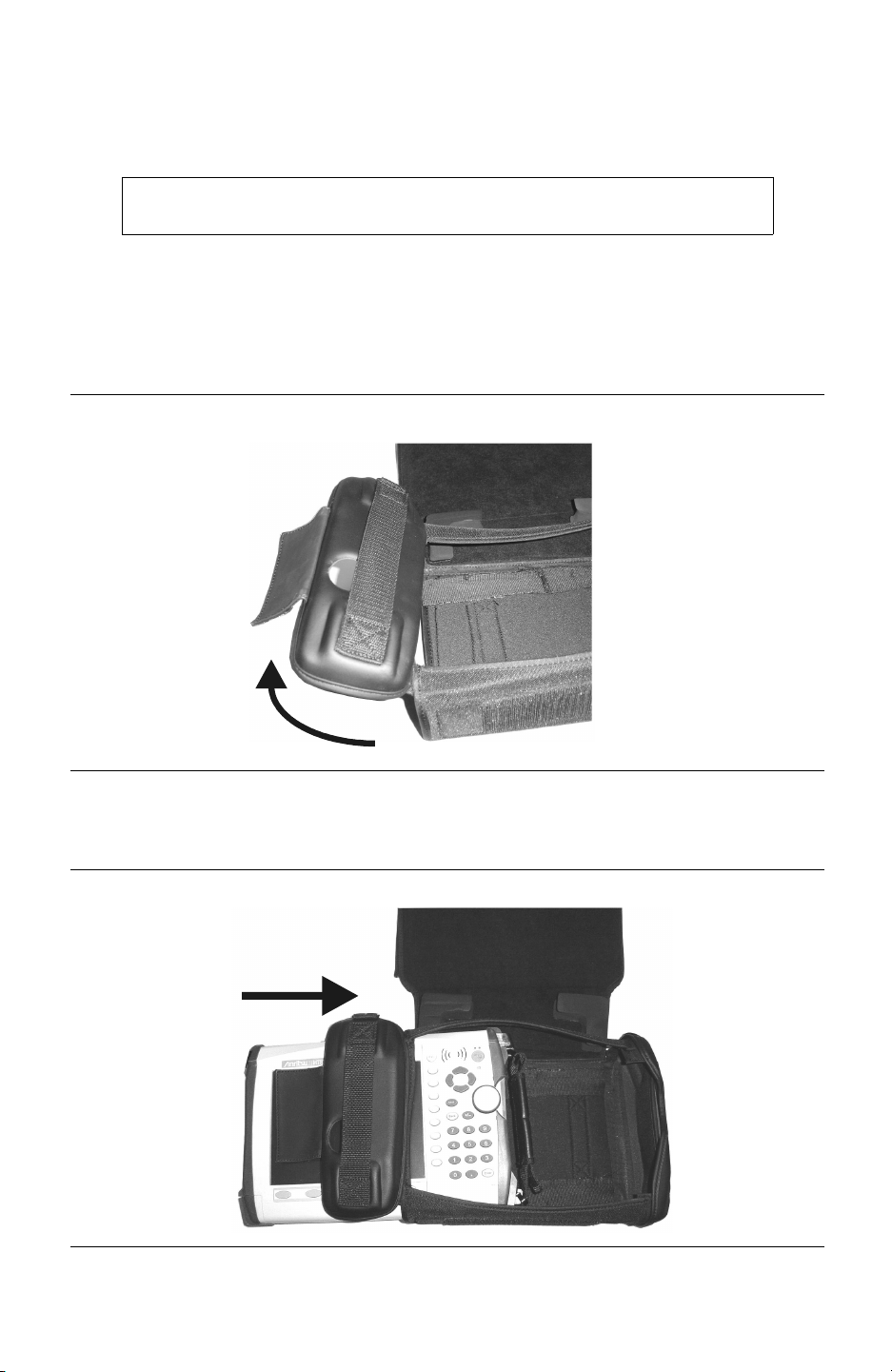
Step 3. Release the hook and loop fastener panel on the back left of the case to open the
left side cover. Raise the left side cover as shown below.
Table 2: Soft Case Left Side Cover
Step 4. Carefully slide the instrument into the soft carrying case as shown.
Table 3: Inserting the Instrument into the Soft Case
1-11

Step 5. When sliding the instrument into the soft carrying case, take care to lift the upper-
left strap as necessary to clear the connectors.
Lift strap to clear
connectors
Table 4: Clearing the Connectors
Step 6. The instrument is fully seated when the carrying strap on th e rig ht side of the case
is easily accessible. Close the left side cover and reattach the hook and loop fas-
tener panel.
The soft carrying case includes a d etachable should er s trap which can b e co nnected to the Drings on the upper corners of the case as required for comfort or convenience.
1-12

Tilt Bail Stand Installation
The supplied Tilt Bail can be installed for desktop operation. When properly installed, the
tilt bail provides a backward tilt for improved stability and air flow. When the tilt bail is
installed, the unit cannot be placed into the soft carrying case. The tilt bail kit (part number
64343) is a standard accessory supplied with the MS2721A and consists of:
Part Number Qty. Description
64344 1 Tilt Bail
64354 1 Right Support Bumper Assembly
64355 1 Left Support Bumper Assembly
4905-2691 2 M3 x 12 mm stainless steel slotted pan head screw
5905-2692 2 6.2 mm OD stainless steel split lock washer
Step 1. If the instrument is in the soft carrying case, release the hook and loop fastener
flap at the left rear of the case and open the left side flap. Pull the instrument
straight out of the left side of the case.
NOTE: When the tilt bail is installed, the unit cannot be placed back into
the soft carrying case.
Step 2. With a flat-blade screwdriver, remove only the top screw from the carrying strap
D-ring holder on the right side of the instrument. Save the screw and the D-ring
holder, as they will need to be reinstalled if the tilt bail is removed.
Step 3. Remove the carrying strap D-ring from the holder removed in Step 2 and install
the D-ring on to the new right support bumper assembly, item number 64354.
Step 4. Using one M3 x 12 mm stai nless steel s lott ed pan head scr ew and one 6. 2 m m OD
stainless steel split lock washer provided, install the new right support bumper
assembly on to the instrument.
NOTE: Do not use the screw removed in Step 2 to install the new right
support bumper assembly on to the instrument. Use only the screws provided with the kit.
Step 5. Use the other M3 x 12 mm stainless steel slotted pan head screw and 6.2 mm OD
stainless steel split lock washer to attach the left support bumper assembly, item
number 64355, to the left side of the instrument.
Step 6. Flex the tilt bail to install it into the two bumper assemblies.
Table 5: Tilt Bail Installed
1-13

Anritsu Service Centers
UNITED STATES
ANRITSU COMPANY
490 Jarvis Drive
Morgan Hill, CA 95037-2809
Telephone: 1-800-ANRITSU
FAX: 408-776-1744
ANRITSU COMPANY
10 New Maple Ave., Unit 305
Pine Brook, NJ 07058
Telephone: (973) 227-8999
1-800-ANRITSU
FAX: 973-575-0092
ANRITSU COMPANY
1155 E. Collins Blvd
Richardson, TX 75081
Telephone: 1-800-ANRITSU
FAX: 972-671-1877
AUSTRALIA
ANRITSU PTY. LTD.
Unit 21, 270 Ferntree Gully Road
Notting Hill, VIC 3168
Australia
Telephone: 03-9558-8177
FAX: 03-9558-8255
FRANCE
ANRITSU S.A
9 Avenue du Quebec
Zone de Courtaboeuf
91951 Les Ulis Cedex
Telephone: 016-09-21-550
FAX: 016-44-61-065
GERMANY
ANRITSU GmbH
Konrad-Zuse-Platz 1
81829 Muenchen, Germany
Telephone: +49 89 4423080
FAX: +49 89 44230855
INDIA
MEERA AGENCIE S PVT. LTD.
23 Community Centre
Zamroodpur, Kailash Colony
Extension,
New Delhi, India 110 048
Phone: 011-2-6442700/6442800
FAX : 011-2-6442500
ISRAEL
TECH-CENT, LT D.
4 Raul Valenberg St
Tel-Aviv 69719
Telephone: (03) 64-78-563
FAX: (03) 64-78-334
SINGAPORE
ANRITSU (SINGAPORE) PTE
LTD.
10, Hoe Chiang Road
#07-01/02 Keppel Towers
Singapore 089315
Telephone: 6282-2400
FAX: 6282-2533
SOUTH AFRICA
ETECSA
12 Surrey Square Office Park
330 Surrey Avenue
Ferndale, Randburg, 2194
South Africa
Telephone: 27-11-787-7200
FAX: 27-11-787-0446
SWEDEN
ANRITSU AB
Borgafjordsgatan 13
164 40 Kista
Telephone: (08) 534-707-00
FAX: (08) 534-707-30
TAIWAN
ANRITSU CO., INC.
7F, No. 316, Section 1
NeiHu Road
Taipei, Taiwan, R.O.C.
Telephone: 886-2-8751-1816
FAX: 886-2-8751-2126
BRAZIL
ANRITSU ELECTRONICA LTDA.
Praia de Botafogo, 440, Sala
2401
CEP22250-040, Rio de Janeiro,
RJ, Brasil
Telephone: 021-527-6922
FAX: 021-53-71-456
CANADA
ANRITSU INSTRUMENTS LTD.
700 Silver Seven Road, Suite 120
Kanata, Ontario K2V 1C3
Telephone: (613) 591-2003
FAX: (613) 591-1006
CHINA
ANRITSU ELECTRONICS
(SHANGHAI) CO. LTD.
2F, Rm B, 52 Section Factory
Building
No. 516 Fu Te Rd (N)
Shanghai 200131 P.R. China
Telephone:21-58680226,
58680227, 58680228
FAX: 21-58680588
1-14
ITALY
ANRITSU Sp.A
Roma Office
Via E. Vittorini, 129
00144 Roma EUR
Telephone: (06) 50-99-711
FAX: (06) 50-22-4252
JAPAN
ANRITSU CUSTOMER SERVICES LTD.
5-1-1 Onna, Atsugi-shi
Kanagawa-Ken, 243-0032, Japan
Telephone: 0462-96-6688
FAX: 0462-25-8379
KOREA
ANRITSU CORPORATION LTD.
Service Center:
8F Hyunjuk Building
832-41, Yeoksam Dong
Kangnam-Ku
Seoul, South Korea 135-080
Telephone: 82-2-553-6603
FAX: 82-2-553-6605
UNITED KINGDOM
ANRITSU LTD.
200 Capability Green
Luton, Bedfordshire
LU1 3LU, England
Telephone: 015-82-433200
FAX: 015-82-731303
Chapter 2 Quick Start Guide
Introduction
This chapter provides a brief overview of the Anritsu MS2721A Spectrum Master. The
intent of this chapter is to provide the user with a starting point for making basic measurements. For more detailed information, see Chapter 3, Key Functions and Chapter 4, Mea-
surement Fundamentals.
Turning the MS2721A On for the First Time
The Anritsu MS2721A Spectrum Master is capable of up to three hours of continuous operation from a fully charged, field-replaceab le battery (see Chapter 1). The MS2721A can als o
be operated from a 12 VDC source (which will also simultaneously charge the battery). This
can be achieved with either the Anritsu AC-DC Adapter (Anritsu part number 40-168) or 12
VDC Automotive Cigarette Lighter Adapter (Anritsu part number 806-141). Both items are
included as standard accessories (see the list of accessories in Chapter 1).
CAUTION
When using the Automotive Cigarette Lighter 12 VDC Adapter, Anritsu Part Number
806-141, always verify that the sup ply i s rated fo r a mini mum of 60 Watts @ 12 VDC,
and that the socket is clear of any dirt or debris. If the adapter plug becomes hot to the
touch during operation, discontinue use immediately.
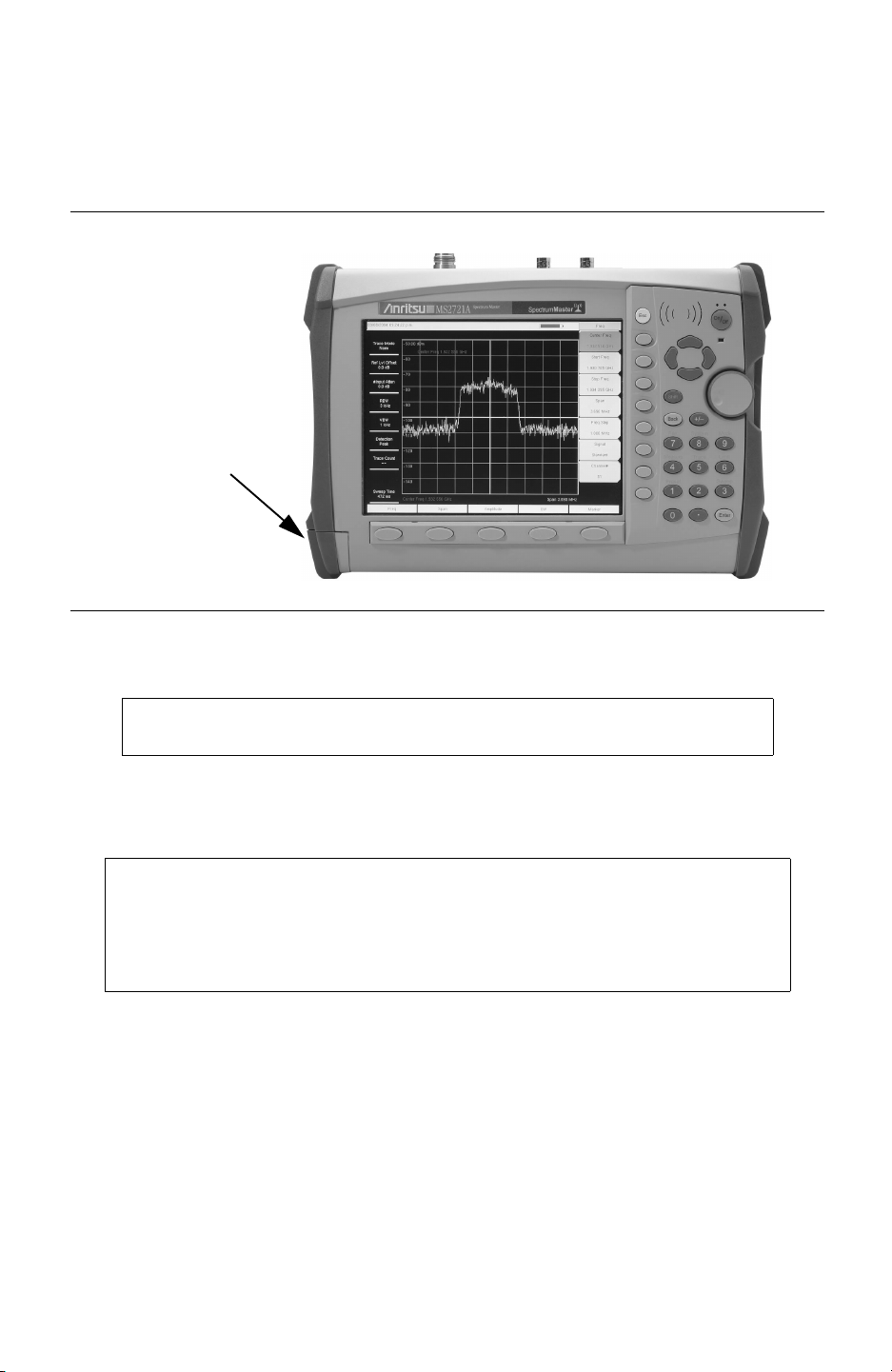
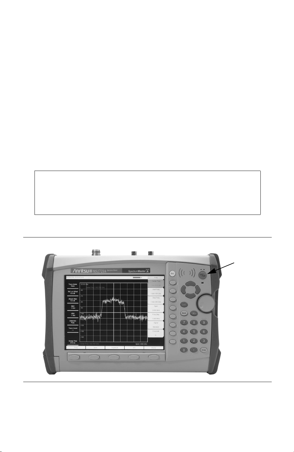
To turn on the MS2721A, press the
Figure 2-1. MS2721A On/Off Button
The MS2721A Spectrum Master takes about thirty-five seconds to complete power up and
load the application software. At the completion of this process, the instrument is ready to
use.
On/Off front panel button (Figure 2-1 ).
On/Off
Button
2-1

For information on making measurements with the Spectrum Master, refer to “Making a
Spectrum Analyzer Measurement,” later in this chapter. For advanced applications, refer to
Chapter 4, Measurement Fundamentals, and Chapter 5, Field Measurements.
Front Panel Overview
The Spectrum Master menu-driven interface is easy to use and requires little training. Hard
keys on the front panel are used to initiate function-specific menus. There are five function
hard keys located below the display: Frequency, Span, Amplitude, Bandwidth and Marker.
There are 21 hard keys and a rotary knob located to the righ t of the display. Eight of the hard
keys are dual purpose, depending on the current mode of operation. The dual-purpose keys
are labeled with a number on the key itself, and the alternate function printed on the panel
above the key. Use the shift key to access the functions printed on the panel. The
key, used for aborting data entry, is the round button located above soft keys. The rotary
knob and the keypad can both be used to change the value of an active parameter.
There are also eight soft keys to the right of the display which change function depending
upon the current menu selection. The current soft key function is indicated in the active
function block to the right of the display. The locations of the different keys are shown in
Figure 2-2, below.
Escape
Fan Exhaust
Port
Fan Exhaust
Port
Function Hard Keys
Figure 2-2. Spectrum Master Overview
Active Function
Block
Escape
Key
Soft
Keys
Fan Inlet
Charge
Fault LED
Battery
Charge
LED
Shift Key
Rotary
Knob
Keypad
Battery Charge LED (green)
The Battery Charge LED will flash if the battery is charging, and remain on steady when the
battery is fully charged.
Charge Fault LED (red)
The Charge Fault LED will remain on steady under a battery charger fault condition. Fault
conditions include a battery cell voltage that is too low to charge, or a battery temperature
outside the temperature range (-5º C to +50º C) to charge.
2-2
Fan Inlet and Exhaust Ports
It is important to keep the fan inlet and exhaust ports clear of obstructions at all times for
proper ventilation and c ooling of the instrument.
Display Overview
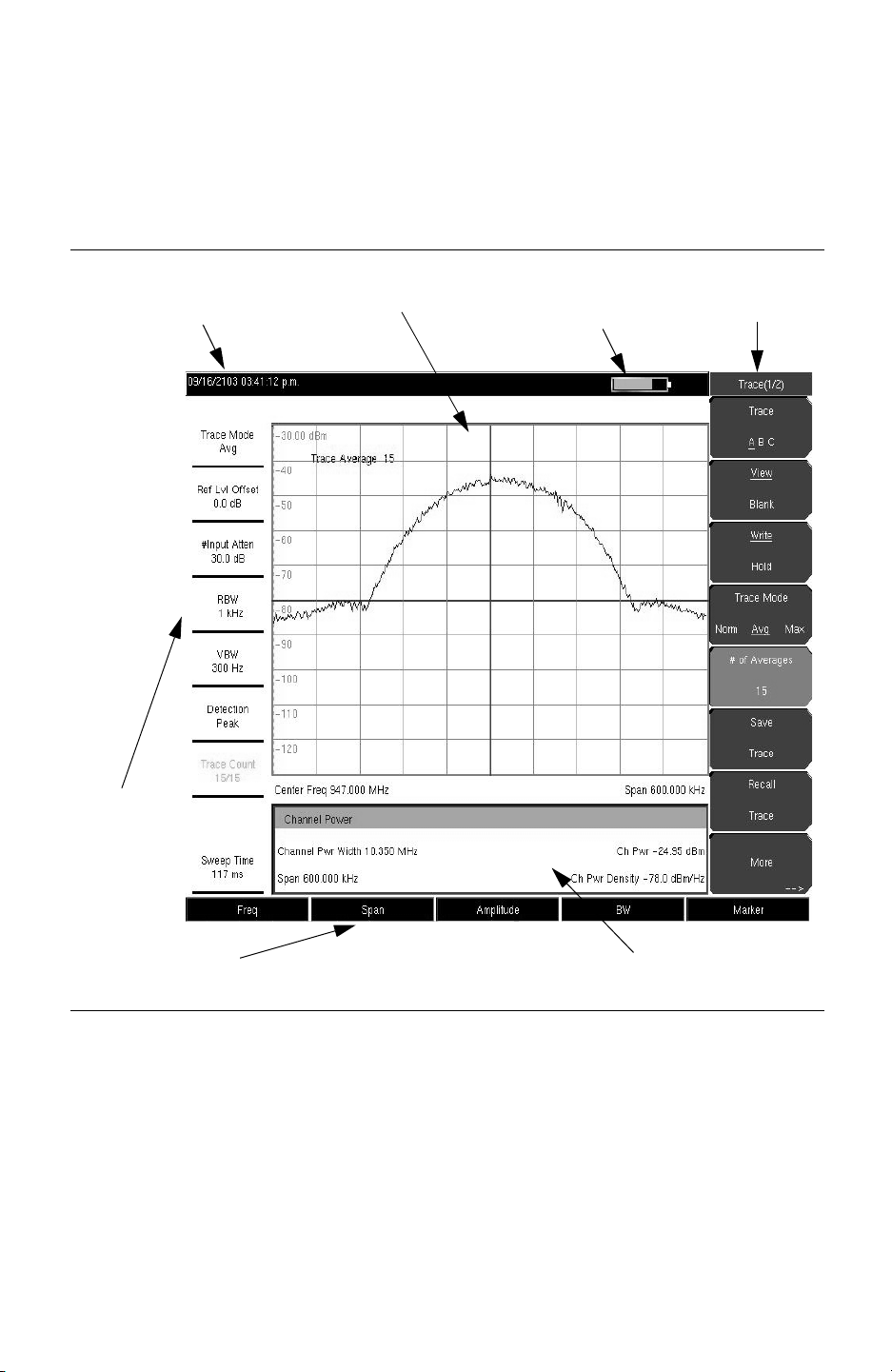
Figure 2-3 illustrates some of the key information areas of the MS2721A display. Refer to
Chapter 3, Key Functions, for more detailed key descriptions.
Real Time
Instrument
Settings
Summary
Clock
Display Area
Battery Charge
Indicator
Soft Key
Labels
Hard Key Labels
Figure 2-3. Display Overview
Optional Data Window
2-3

Test Panel Connectors
The connectors and indicators located on the test panel are shown in Figure 2-4 and
described below.
External
Power
LAN Connection
USB Interface
External Trigger
Headset
Jack
Compact Flash Socket Fan Exhaust Port
External Frequency
Reference
RF In
Figure 2-4. Test Panel Connectors
External Power
The external power connector is used to power the unit and for battery charging. Input is 12
to 15 VDC at up to 5.0A. A green flashing indicator light near the power switch shows that
the instrument battery is being charged by the external charging unit. The indicator is
steadily illuminated when the battery is fully charged.
WARNING: When using the AC-DC Adapter , always use a three-wire p ower cable
connected to a three-wire power line outlet. If power is supplied without grounding the equipment in this manner, there is a risk of receiving a severe or fatal electric shock.
LAN Connection
The RJ-45 connector is used to connect the Spectrum Master to a local area network. Integrated into this connector are two LEDs. The amber LED indicates the presence of LAN
voltages—a live LAN connection—while the green LED flashes to s how that LAN traffic is
present. The instrument IP address is set by pressing the
followed by the
System Options soft key and the Ethernet Config soft key. The instrument
Shift key, then the System (8) key
Ethernet address can be set automatically using DHCP, or manually by entering the desired
IP address, gateway address and subnet mask.
Dynamic Host Configuration Protocol (DHCP) is an Internet protocol that automates the
process of setting IP addresses for devices that use TCP/IP , an d is the most common method
of configuring a device for network use. To determine if a network is set up for DHCP, connect the MS2721A to the network and select DHCP protocol in the
Ethernet C onfig menu.
2-4
Turn the Spectrum Master off, and then on. If the network is set up for DHCP, the assigned
IP address should be displayed briefly after the power up sequence.
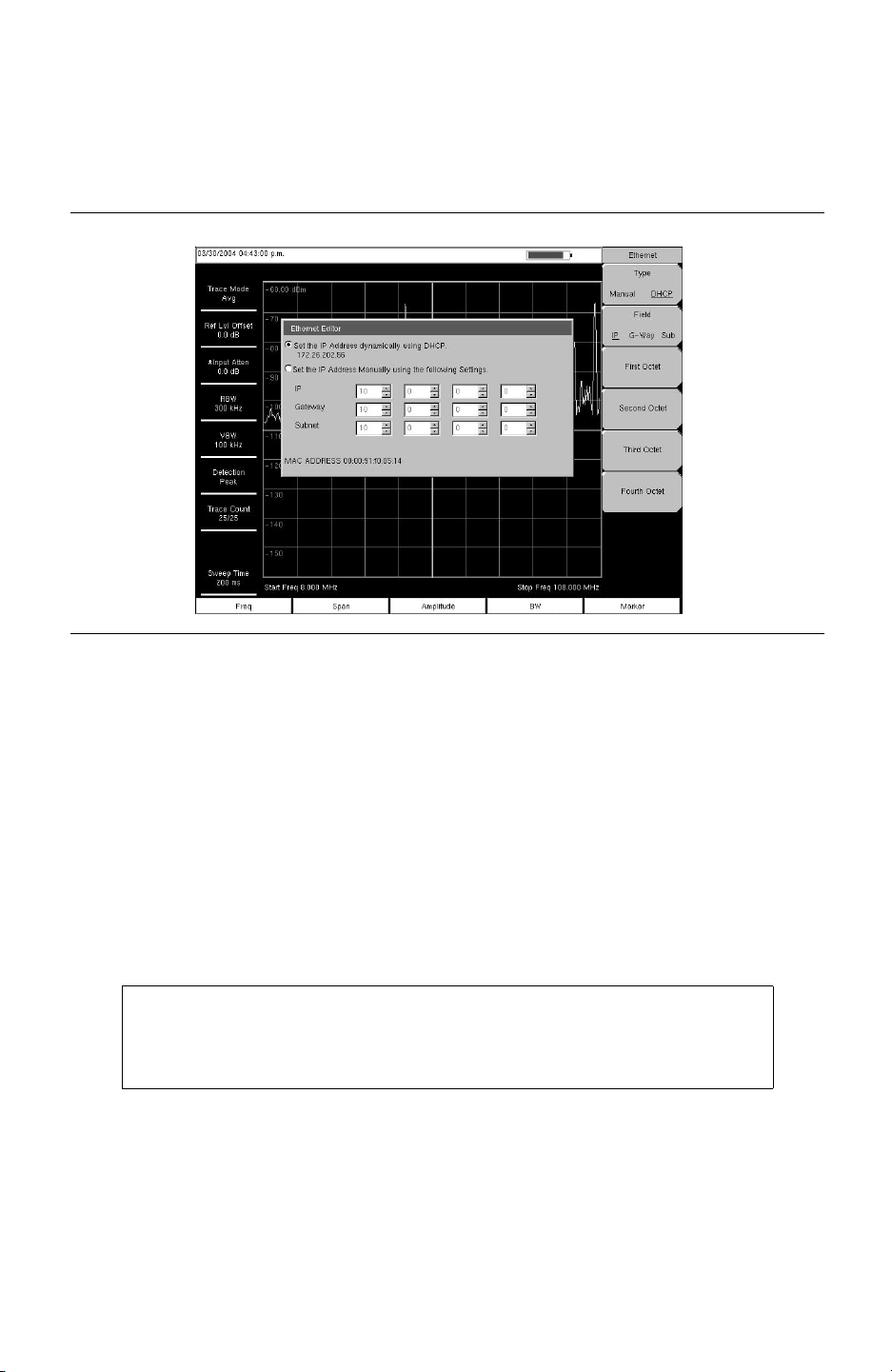
To display the IP address with the instrument on, press the
then the
displayed as shown in Figure 2-5.
Figure 2-5. IP Address Assigned Using DHCP
System Options soft key and th e Ethernet Config soft key. The IP address will be
Shift key, then the System key,
More about DHCP
DHCP stands for Dynamic Host Configuration Protocol. It is a protocol that allows a server
to dynamically assign IP addresses to devices that are connected to the network. Most networks include a DHCP server to manage IP addresses. When a DHCP server is available on
the network, DHCP is the preferred IP address mode.
When using DHCP, no setup is required to lease and use a dynamic IP address. In a dynamic
IP operation, the IP address in use may change from use to us e. The DHC P serve r han ds out
IP addresses on a first come, first served basis. As soon as the device is disconnected from
the network, the IP address that it was using becomes available to lease to the next unit
requesting an IP address. Normally there is some amount of lag time on the DHCP server
end, so if the device is connected again reasonably soon, it may end up with the same
address.
NOTE: The MS2721A must be connected to the network before it i s turned
on for DHCP to work. Key elements of the DHCP lease are only performed
during the instrument's startup operations, or when switching from manual
to DHCP.
When a DHCP server is not available, a Static IP address can be used. A Static IP address is
a fixed address. Once set, it will always remain the same and care must be taken to not conflict with other equipment on the network.
When using a static IP ad dres s on an es ta bli shed network, always request a Static IP address
from the network administrator. Randomly choosing a Static IP address on an established
network may result in duplicate IP addresses or other conflicts.
Three parameters must be set prior to using a Static IP address:
2-5

IP Address
This is the Static IP address on the network.
Default Gateway
Often when a static IP address is assigned, a default gateway is also identified. If the
default gateway is unknown, type in the Static IP address so that the Static IP address and
Default Gateway are the same number.
Subnet Mask
This parameter is usually extracted from the Static IP address based on the class of the
address and determines the destination of any broadcast messages that might be sent from
the instrument. It can be customized if necessary. The subnet mask may also be provided
with the Static IP address.
Example 1
In this example, a Static IP address has been chosen because there is no network available.
The instrument is connected to the network port on the PC with a crossover Ethernet cable
(not included). This is also referred to as Direct Connect:
IP Address: 10.0.0.2
Default Gateway: 10.0.0.2
Subnet Mask: 255.255.0.0
Example 2
In this example, the Static IP address has been assigned with an associated gateway and sub-
net mask:
IP Address: 153.56.100.42
Default Gateway: 153.56.100.1
Subnet Mask: 255.255.252.0
There are a few tools built into the Microsoft Windows operating system that can assist in
making some determinations about the network the PC is plugged into. Typing
command prompt will display information about the in-use parameters of the PC and its network connection. Below is an example of the typical results expected.
NOTE: The ipconfig display does not report if the information is from a
DHCP server or a Static IP setup.
Y:\>ipconfig
Windows 2000 IP Configuration
Ethernet adapter Local Area Connection:
Connection-specific DNS Suffix. : us.anritsu.com
IP Address. . . . . . . . . . . . : 172.26.202.172
Subnet Mask . . . . . . . . . . . : 255.255.252.0
Default Gateway . . . . . . . . . : 172.26.200.1
Another tool that can find out if a selected IP address is already on the network is
is a harmless way to determine if an address is found on the network, and if it is found, for it
to reply. Greatly simplified, ping sends out a request to a specific address to determine if it is
there. If it is found, it will respond by sending back what was sent to it. If it is not found, the
response will be "
Y:\>ping 172.26.202.172
Pinging 172.26.202.172 with 32 bytes of data:
Reply from 172.26.202.172: bytes=32 time<10ms TTL=128
Reply from 172.26.202.172: bytes=32 time<10ms TTL=128
Reply from 172.26.202.172: bytes=32 time<10ms TTL=128
request timed out" meaning that there was no reply from that IP address.
ipconfig at a
ping. Ping
2-6

Reply from 172.26.202.172: bytes=32 time<10ms TTL=128
Ping statistics for 172.26.202.172:
Packets: Sent = 4, Received = 4, Lost = 0 (0% loss),
Approximate round trip times in milli-seconds:
Minimum = 0ms, Maximum = 0ms, Average = 0ms
USB Interface
The USB 2.0 interface can be used to connect the MS2721A Spectrum Master directly to a
PC. The first time the MS2721A is connected to a PC, the normal USB device detection by
the computer operating system will take place. The CD-ROM shipped with the instrument
contains a driver for Windows 2000 and Windows XP that is ins talled wh en Master Soft ware
Tools is installed. Drivers are not available for earlier versions of the Windows operating
system. During the driver installation pro cess, place the C D-ROM in the compu ter drive and
specify that the installation wizard should search the CD-ROM for the driver.
NOTE: Install Master Software Tools (see Chapter 8) before connecting
the instrument to the PC USB port.
Headset Jack
The headset jack provides audio output from the built-in AM/FM/SSB demodulator and
other audio signals for testing and troubleshooting wireless communication systems. The
jack accepts a 2.5 mm 3-wire miniature phone plug such as those commonly used with cellular telephones.
Ext Trigger
A TTL signal applied to the
sweep to occur. This mode is used in zero span, and triggering occurs on the rising edge of
the signal. After the sweep is complete, the resultant trace is displayed until the next trigger
signal arrives.
External Trigger female BNC input connector causes a single
Ext Freq Ref
BNC female connector for connection of an external f requency reference or external trigger.
Select the
nal reference from the list presented. Valid frequencies are 1 MHz, 1.2288 MHz, 1.544
MHz, 2.4576 MHz, 4.8 MHz, 4.9152 MHz, 5 MHz, 9.8304 MHz, 10 MHz, 13 MHz and
19.6608 MHz at amplitude from -10 dBm to +10 dBm.
RF In
50
Ω
Compact Flash
The Spectrum Master is shipped with a 64 MB Compact Flash Memory Module, Anritsu
Part Number 2000-1358. The removable compact flash card can be any size, although it
must be a minimum of 64 MB to be able to hold the entire contents of the internal flash
memory.
Ext Ref Freq soft key under the System menu to select the frequency of the exter-
Type-N female connector.
2-7
 Loading...