

http://www.anritsu.com 322
The MS2721A is the first handheld spectrum analyzer to deliver the
ability to measure very low level signals with a displayed average
noise level of ≤-153 dBm typical @ 1 GHz in a 10 Hz RBW. Coupled
with a wide range of resolution bandwidth choices, you can configure the Spectrum Master to meet your most challenging measurement needs. As the spectrum becomes more and more congested,
the ability to measure low level, closely spaced signals becomes
more and more important not only for interference detection but also
for wireless system planning.
Operating convenience is of paramount important importance when
equipment is used in the field. The input attenuation value can be tied
to the reference lev el, reducing the number of parameters a field technician may have to set. The RBW/VBW and the span/RBW ratios can
be set to values that are best for the measurements being made, further easing the technician’s burden and reducing the chances of errors. Thousands of traces with names up to 15 characters long may
be saved in the 64 MB non-volatile compact flash memory. These
traces can later be copied into a PC using the built-in USB 2.0 connector or the 10/100 MHz Ethernet connection, or by copying them
to an external Compact Flash card. The MS2721A Spectrum Master
has a very wide dynamic range (>80 dB), allowing measurement of
very small signals in the presence of much larger signals.
Resolution bandwidth and video bandwidth can be independently set
to meet a user’s measurement needs. In addition the input attenuator value can be set by the user and the preamplifier can be turned
on or off as needed. For maximum flexibility, sweep triggering can be
set to free run, or to do a single sweep.
Light Weight
Weighing about six pounds, including a Li-Ion battery, this fully functional handheld spectrum analyzer is light enough to take anywhere,
including up a tower.
With the supplied Remote Access Software you can control an
MS2721A that is miles away, seeing the screen display and operating with an interface that looks exactly like the instrument itself.
The MS2721A features eight languages English, Spanish, German,
French, Japanese, Chinese, Italian and Korean, plus two custom,
user defined languages can be uploaded into the instrument using
Master Software Tools, supplied with the instrument.
Fast Sweep Speed
The MS2721A can do a full span sweep in ≤900 milliseconds, and
sweep speed in zero span can be set from less than 50 microseconds up to over 4000 seconds. This is faster and more flexible than
any portable spectrum analyzer on the market today, simplifying the
capture of intermittent interference signals.
+43 dBm Maximum Safe Input Level
Because the MS2721A can survive an input signal of +43 dBm – 20
watts – without damage, you can rest assured that the MS2721A can
survive in even the toughest RF environments.
Spectrum Monitoring
A critical function of any spectrum analyzer is the ability to accurately view a portion of the RF and microwave spectrum. The MS2721A
performs this function admirably thanks to the wide frequency range
and excellent dynamic range. A built-in 64 MB compact flash memory module allows over 2000 traces to be stored. An external compact
flash socket allows additional compact flash memory to expand the
trace storage without limit.
Multiple Markers
Display up to six markers on screen, each with delta marker capability.
In addition you may select a marker table that simultaneously shows
the status of all markers. In the table you can see the frequency, and
amplitude measurement value for all markers along with delta frequency and delta amplitude. Each marker can have not only a measurement reference frequency but also a delta frequency and delta
amplitude, effectively giving y ou up to twelv e markers if y ou need them!
Noise Markers
The capability to measure noise level in terms of dBm/Hz or
dBµV/Hz is a standard feature of the MS2721A.
Frequency Counter Markers
The MS2721A Spectrum Master has frequency counter markers with
resolution to 1 Hz. Tie this capability to an external precision time
base to get complementary accuracy and resolution.
Smart Measurements
The MS2721A has dedicated routines for smart measurements of
field strength, channel power, occupied bandwidth, Adjacent
Channel Power Ratio (ACPR) and C/I.
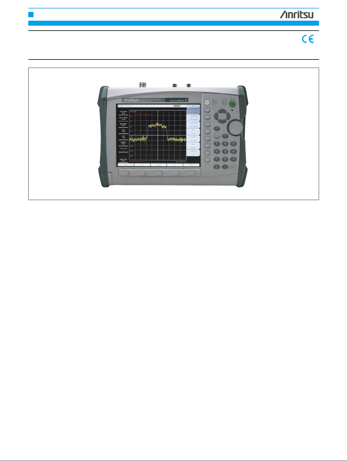
HANDHELD MEASURING INSTR UMENTS
SPECTRUM MASTER
MS2721A
100 kHz to 7.1 GHz
High Performance Handheld Spectrum Analyzer
NNNNEEEEWW
WW
http://www.anritsu.com 323
5
HANDHELD MEASURING INSTR UMENTS
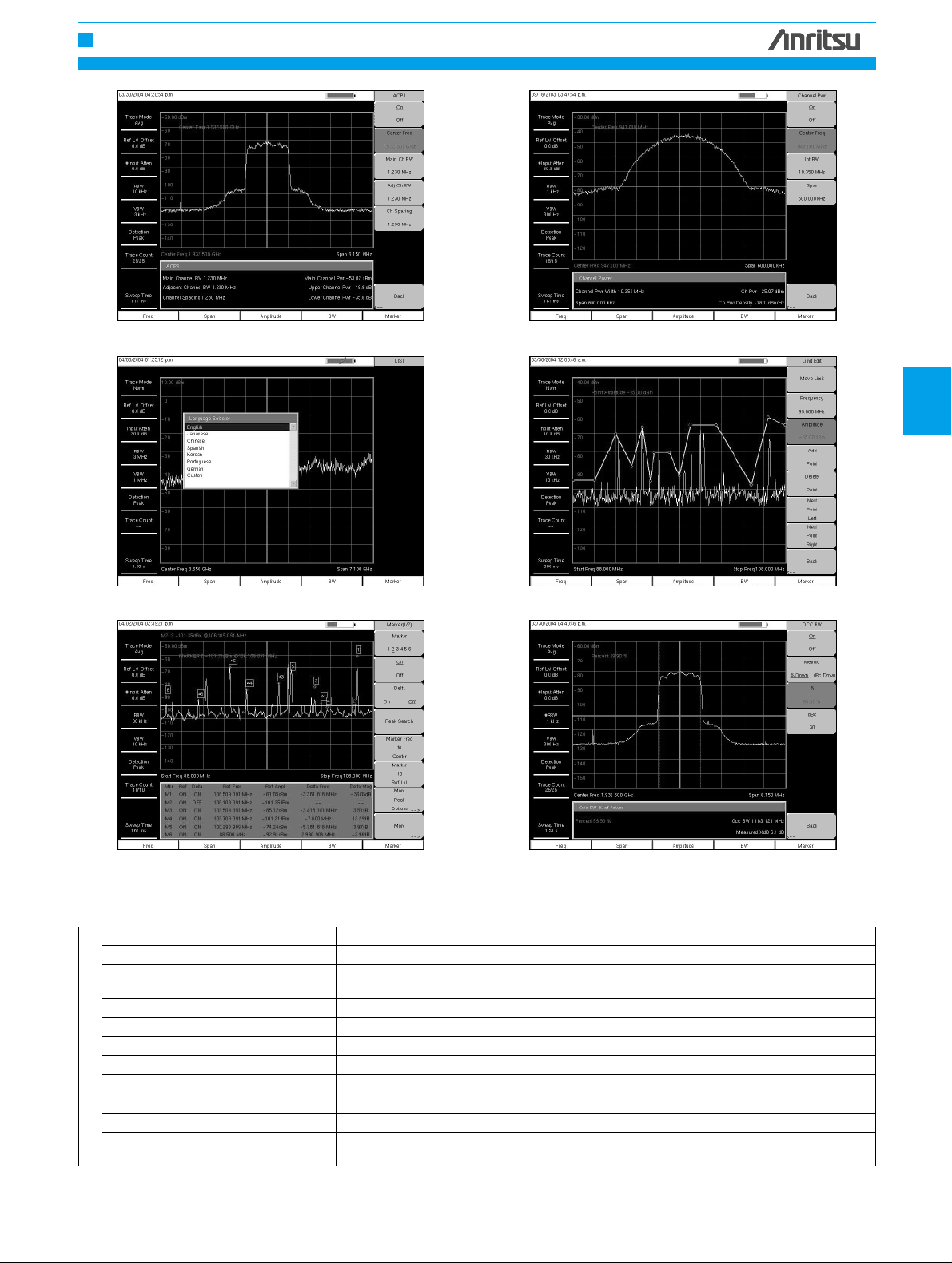
Adjacent Channel Power Ratio Measurement of Channel Power for a GSM Signal
Multiple Language Support Segmented Limit Line
Multiple Markers plus Multiple Delta Markers Occupied Bandwidth
Frequency
Frequency Range 100 kHz to 7.1 GHz (useable to 9 kHz)
Tuning resolution 1 Hz
Frequency Reference
Aging ±1 ppm/year
Accuracy ±1 ppm (25°C ± 25°C) + long term dr ift
Frequency Span 10 Hz to 7.1 GHz plus 0 Hz (zero span)
Span Accuracy Same as frequency reference accuracy
Sweep Time minimum 100 ms, 50 µs in zero span
Sweep Time Accuracy ± 2% in zero span
Sweep Trigger Free run, Single, Video, External
Resolution Bandwidth (-3 dB width) 10 Hz to 3 MHz in 1-3 sequence ± 10% , 8 MHz demodulation bandwidth
Video Bandwidth (-3 dB) 1 Hz to 3 MHz in 1-3 sequence
SSB Phase Noise
-100 dBc/Hz max at 10, 20 & 30 kHz offset from carrier
-102 dBc/Hz max at 100 kHz offset from carrier
Specifications
Continued on next page

http://www.anritsu.com 324
HANDHELD MEASURING INSTR UMENTS
Amplitude
Measurement Range DANL to +30 dBm
Absolute amplitude accuracy
(Power levels ≥-50 dBm, ≤35 dB input
attenuation, preamp off)
100 kHz to ≤ 10 MHz ±1.5 dB
>10 MHz to 4 GHz ±1.25 dB
>4 GHz to 7.1 GHz ±1.75 dB
Second Harmonic Distortion (0 dB input
attenuation, -30 dBm input)
-50 dBc, 0.05 to 0.75 GHz
-40 dBc, >0.75 to 1.05 GHz
-50 dBc, >1.05 to 1.4 GHz
-70 dBc, >1.4 to 2 GHz
-80 dBc, > 2 GHz
Third Order Intercept (TOI) (preamplifier off)
Frequency Typical
50 MHz to 300 MHz >8 dBm
>300 MHz to 2.2 GHz >10 dBm
>2.2 GHz to 2.8 GHz >15 dBm
>2.8 GHz to 4.0 GHz >10 dBm
>4.0 GHz to 7.1 MHz >13 dBm
Displayed Average Noise Level
DANL in 10 Hz RBW, dBm
Frequency Preamp On
Typical Max
10 MHz to 1 GHz -153 dBm -151 dBm
>1 GHz to 2.2 GHz -150 dBm -149 dBm
>2.2 GHz to 2.8 GHz -146 dBm -143 dBm
>2.8 GHz to 4.0 GHz -150 dBm -149 dBm
>4.0 GHz to 7.1 GHz -148 dBm -146 dBm
Noise Figure
(Derived from DANL measurement)
0 dB attenuation, reference level -50 dBm,
23°C, preamplifier on
Frequency Typical
10 MHz to 1.0 GHz 11 dB
>1 GHz to 2.2 GHz 14 dB
>2.2 GHz to 2.8 GHz 18 dB
>2.8 GHz to 4.0 GHz 14 dB
>4.0 GHz to 7.1 GHz 16 dB
Display Range 1 to 15 dB/div in 1 dB steps. Ten divisions displayed.
Amplitude Units Log Scale modes dBm, dBV, dBmv, dBµV
Linear Scale Modes nV, µV, mV, V, kV, nW, µW, mW, W, kW
Attenuator range 0 to 65 dB
Attenuator resolution 5 dB steps
Input-Related Spurious
-60 dBc max*, (<-70 dBc typical), -30 dBm input, 0 dB RF attenuation
*Exceptions:
Input frequency Spur Level
1674 MHz -46 dBc max (-56 dBc typical), 0 to 2800 MHz
>1674 to 1774 MHz -50 dBc max (-60 dBc typical) at (Finput – 1674 MHz)
>1774 to 2900 MHz -48 dBc max (-68 dBc typical) at (Finput – 1674 MHz)
Residual Spurious, preamp off
(RF input terminated, 0 dB RF attenuation)
-90 dBm max**, 100 kHz to <3200 MHz
-84 dBm max**, 3200 to 7100 MHz
**Exceptions:
Frequency Spur Level
250, 300 & 350 MHz -85 dBm max
~4010 MHz -80 dBm max (-90 dBm typical)
~5084 MHz -70 dBm max (-83 dBm typical)
~5894 MHz -75 dBm max (-87 dBm typical)
~7028 MHz -80 dBm max (-92 dBm typical)
Residual Spurious, preamp on:
-100 dBm max
(RF input terminated, 0 dB RF attenuation)
General
Maximum Continuous Input ≥10 dB attenuation, +30 dBm
Input Damage Level
≥10 dB attenuation, >+43 dBm, ±50 Vdc
<10 dB attenuation, >+23 dBm, ±50 Vdc
RF Input VSWR 2.0:1 maximum, 1.5:1 typical (≥10 dB attenuation)
Reference Level Adjustable over amplitude range
ESD Damage Level >10 kV ≥10 dB attenuation
Functions
Multiple Marker Display up to six markers on screen, each marker includes a delta marker.
Marker Table Display a table of up to six marker frequency and amplitude values plus delta marker
frequency offset and amplitude.
Upper & Lower Limit Lines Each upper and lower limit can contain up to 40 segments.

http://www.anritsu.com 325
HANDHELD MEASURING INSTR UMENTS
5
Ordering Information
Please specify model/order number, name, and quantity when ordering.
Model/Order No.
Name
MS2721A Handheld Spectr um Analyzer : 100 kHz to 7.1 GHz
Standard Accessories
10580-00103 MS2721A User's Guide
61382 MS2721A Soft Carrying Case
2300-498 Master Products Software Tools Program CD ROM
633-44 Rechargeable Li-Ion Battery
40-168 AC-DC Adapter
806-62 Automotive Cigarette Lighter 12 Volt DC Adapter
2000-1360 USB A/mini-B Cable
2000-1371 Ethernet Cable, 7 feet (213 cm)
1091-27 Type-N male to SMA female Adapter
1091-172 Type-N male to BNC female Adapter
Optional Accessories
42N50A-30 30 dB, 50W, Bi-dir., DC-18 GHz, N(m) to N(f) Attenuator
34NN50A Precision Adapter, DC to 18 GHz, 50 , N(m) to N(m)
34NFNF50C Precision Adapter, DC to 18 GHz, 50 , N(f) to N(f)
15NNF50-1.5B Test port cable armored, 1.5 meter, N(m) to N(f),
18.0 GHz
15NNF50-1.5B Test port cable, armored, 1.5 meter N(m) to N(f) 18 GHz
15NN50-1.5C Test port cable armored, 1.5 meter, N(m) to N(m), 6 GHz
15NN50-3.0C Test port cable armored, 3.0 meter, N(m) to N(m), 6 GHz
15NN50-5.0C Test port cable armored, 5.0 meter, N(m) to N(m), 6 GHz
15NNF50-1.5C Test port cable armored, 1.5 meter, N(m) to N(f), 6 GHz
15NNF50-3.0C Test port cable armored, 3.0 meter, N(m) to N(f), 6 GHz
15NNF50-5.0C Test port cable armored, 5.0 meter, N(m) to N(f), 6 GHz
15ND50-1.5C Test port cable armored, 1.5 meter, N(m) to 7/16 DIN(m),
6.0 GHz
15NDF50-1.5C Test port cable armored, 1.5 meter, N(m) to 7/16 DIN(f),
6.0 GHz
Model/Order No.
Name
510-90 Adapter, 7/16 DIN (f) to N(m), DC to 7.5 GHz, 50
Ω
510-91 Adapter, 7/16 DIN (f)-N(f), DC to 7.5 GHz, 50Ω
510-92 Adapter, 7/16 DIN (m)-N(m), DC to 7.5 GHz, 50Ω
510-93 Adapter, 7/16 DIN(m)-N(f), DC to 7.5 GHz, 50Ω
510-96 Adapter 7/16 DIN (m) to 7/16 DIN (m), DC to
7.5 GHz, 50
Ω
1030-86 Band Pass Filter, 800 MHz band, 806-869 MHz,
Loss = 1.7 dB, N(m)-SMA(f)
1030-87 Band Pass Filter, 900 MHz band, 902-960 MHz,
Loss =1.7 dB, N(m)-SMA(f)
1030-88 Band Pass Filter, 1900 MHz band, 1.85-1.99 GHz,
Loss =1.8 dB, N(m)-SMA(f)
1030-89 Band Pass Filter, 2400 MHz band, 2.4-2.5 GHz,
Loss =1.9 dB, N(m)-SMA(f)
510-97 Adapter 7/16 DIN (f) to 7/16 DIN (f), 7.5 GHz
61382 Spare Soft Carrying Case
40-168 Spare AC/DC Adapter
806-62 Spare Automotive Cigarette Lighter 12 Volt DC Adapter
760-229 MS2721A Transit Case
2300-498 Master Software Tools Program CD ROM
10580-00103 Anritsu User's Guide, Model MS2721A
10580-00104 Anritsu Programming Manual, Model MS2721A
10580-00105 Anritsu Maintenance Manual, Model MS2721A
633-44 Rechargeable battery, Li-Ion
2000-1374 Dual Battery charger, Li-Ion with universal power supply
2000-1030 Portable antenna, 50
Ω, SMA (m) 1.71-1.88 GHz
2000-1031 Portable antenna, 50
Ω, SMA (m) 1.85-1.99 GHz
2000-1032 Portable antenna, 50
Ω, SMA (m) 2.4-2.5 GHz
2000-1035 Portable antenna, 50
Ω, SMA (m) 896-941 MHz
2000-1200 Portable antenna, 50
Ω, SMA (m) 806-869 MHz
2000-1361 Portable Antenna, 50
Ω, SMA (m) 5725-5825 MHz
2000-1358 64 MB Compact Flash Memory Module
 Loading...