


MP1861A
56G/64Gbit/s MUX
Operation Manual
Second Edition
For safety and warning information, please read this
manual before attempting to use the equipment.
Additional safety and warning information is provided
in the MP1800A Signal Quality Analyzer Installation
Guide and the MT1810A 4 Slot Chassis Installation
Guide. Please also refer to one of these documents
before using the equipment.
Keep this manual with the equipment.
ANRITSU CORPORATION
Document No.: M-W3756AE-2.0

Safety Symbols
To prevent the risk of personal injury or loss related to equipment malfunction, Anritsu Corporation uses the
following safety symbols to indicate safety-related information. Ensure that you clearly understand the meanings of
the symbols BEFORE using the equipment. Some or all of the following symbols may be used on all Anritsu
equipment. In addition, there may be other labels attached to products that are not shown in the diagrams in this
manual.
Symbols used in manual
DANGER
WARNING
CAUTION
This indicates a very dangerous procedure that could result in serious injury or
death if not performed properly.
This indicates a hazardous procedure that could result in serious injury or death if
not performed properly.
This indicates a hazardous procedure or danger that could result in light-to-severe
injury, or loss related to equipment malfunction, if proper precautions are not taken.
Safety Symbols Used on Equipment and in Manual
The following safety symbols are used inside or on the equipment near operation locations to provide information
about safety items and operation precautions. Ensure that you clearly understand the meanings of the symbols and
take the necessary precautions BEFORE using the equipment.
This indicates an obligatory safety precaution. The obligatory operation is
This indicates a warning or caution. The contents are indicated symbolically in or
This indicates a note. The contents are described in the box.
These indicate that the marked part should be recycled.
This indicates a prohibited operation. The prohibited operation is indicated
symbolically in or near the barred circle.
indicated symbolically in or near the circle.
near the triangle.
MP1861A 56G/64Gbit/s MUX
Operation Manual
15 May 2015 (First Edition)
10 July 2015 (Second Edition)
Copyright © 2015, ANRITSU CORPORATION.
All rights reserved. No part of this manual may be reproduced without the prior written permission of the
publisher.
The contents of this manual may be changed without prior notice.
Printed in Japan
ii
For Safety
Electric Shock
Repair
WARNING
ALWAYS refer to the operation manual when working near locations
at which the alert mark shown on the left is attached. If the advice in
the operation manual is not followed, there is a risk of personal injury
or reduced equipment performance. The alert mark shown on the left
may also be used with other marks and descriptions to indicate other
dangers.
Overvoltage Category
This equipment complies with overvoltage category II defined in IEC
61010. DO NOT connect this equipment to the power supply of
overvoltage category III or IV.
To ensure that the equipment is grounded, always use the supplied
3-pin power cord, and insert the plug into an outlet with a ground
terminal. If power is supplied without grounding the equipment, there
is a risk of receiving a severe or fatal electric shock or causing
damage to the internal components.
Only qualified service personnel with a knowledge of electrical fire and
shock hazards should service this equipment. This equipment cannot
be repaired by the operator. DO NOT attempt to remove the
equipment covers or unit covers or to disassemble internal
components. There are high-voltage parts in this equipment
presenting a risk of severe injury or fatal electric shock to untrained
personnel. In addition, there is a risk of damage to precision
components.
iii
For Safety
Calibration
Falling Over
WARNING
The performance-guarantee seal verifies the integrity of the equipment.
To ensure the continued integrity of the equipment, only Anritsu
service personnel, or service personnel of an Anritsu sales
representative, should break this seal to repair or calibrate the
equipment. Be careful not to break the seal by opening the
equipment or unit covers. If the performance-guarantee seal is
broken by you or a third party, the performance of the equipment
cannot be guaranteed.
This equipment should always be positioned in the correct manner. If
the cabinet is turned on its side, etc., it will be unstable and may be
damaged if it falls over as a result of receiving a slight mechanical
shock.
Always set up the equipment in a position where the power switch
can be reached without difficulty.
iv

For Safety
CAUTION
Cleaning
Check Terminal
Use in a Residential
Environment
Use in Corrosive
Atmospheres
Always remove the main power cable from the power outlet before
cleaning dust around the power supply and fan.
Clean the power inlet regularly. If dust accumulates around the
power pins, there is a risk of fire.
Keep the cooling fan clean so that the ventilation holes are not
obstructed. If the ventilation is obstructed, the cabinet may
overheat and catch fire.
Never input a signal of more than the indicated value between the
measured terminal and ground. Input of an excessive signal may
damage the equipment.
This equipment is designed for an industrial environment.
In a residential environment, this equipment may cause radio
interference in which case the user may be required to take adequate
measures.
Exposure to corrosive gases such as hydrogen sulfide, sulfurous acid,
and hydrogen chloride will cause faults and failures.
Note that some organic solvents release corrosive gases.
solvents release corrosive gases.
v

Equipment Certificate
Anritsu Corporation certifies that this equipment was tested before shipment
using calibrated measuring instruments with direct traceability to public
testing organizations recognized by national research laboratories, including
the National Institute of Advanced Industrial Science and Technology, and
the National Institute of Information and Communications Technology, and
was found to meet the published specifications.
Anritsu Warranty
Anritsu Corporation will repair this equipment free-of-charge if a malfunction
occurs within one year after shipment due to a manufacturing fault.
However, software fixes will be made in accordance with the separate
Software End-User License Agreement. Moreover, Anritsu Corporation will
deem this warranty void when:
The fault is outside the scope of the warranty conditions separately
described in the operation manual.
The fault is due to mishandling, misuse, or unauthorized modification or
repair of the equipment by the customer.
The fault is due to severe usage clearly exceeding normal usage.
The fault is due to improper or insufficient maintenance by the customer.
The fault is due to natural disaster, including fire, wind, flooding,
earthquake, lightning strike, or volcanic ash, etc.
The fault is due to damage caused by acts of destruction, including civil
disturbance, riot, or war, etc.
The fault is due to explosion, accident, or breakdown of any other
machinery, facility, or plant, etc.
The fault is due to use of non-specified peripheral or applied equipment
or parts, or consumables, etc.
The fault is due to use of a non-specified power supply or in a
non-specified installation location.
The fault is due to use in unusual environments
The fault is due to activities or ingress of living organisms, such as
insects, spiders, fungus, pollen, or seeds.
In addition, this warranty is valid only for the original equipment purchaser. It
is not transferable if the equipment is resold.
Anritsu Corporation shall assume no liability for injury or financial loss of the
customer due to the use of or a failure to be able to use this equipment.
(Note)
.
vi

Note:
For the purpose of this Warranty, "unusual environments" means use:
In places of direct sunlight
In dusty places
Outdoors
In liquids, such as water, oil, or organic solvents, and medical fluids, or
places where these liquids may adhere
In salty air or in place chemically active gases (sulfur dioxide, hydrogen
sulfide, chlorine, ammonia, nitrogen dioxide, or hydrogen chloride etc.)
are present
In places where high-intensity static electric charges or electromagnetic
fields are present
In places where abnormal power voltages (high or low) or instantaneous
power failures occur
In places where condensation occurs
In the presence of lubricating oil mists
In places at an altitude of more than 2,000 m
In the presence of frequent vibration or mechanical shock, such as in
cars, ships, or airplanes
Anritsu Corporation Contact
In the event of this equipment malfunctions, contact an Anritsu Service and
Sales office. Contact information can be found on the last page of the printed
version of this manual, and is available in a separate file on the CD version.
vii

r
Notes On Export Management
This product and its manuals may require an Export License/Approval by
the Government of the product's country of origin for re-export from you
country.
Before re-exporting the product or manuals, please contact us to confirm
whether they are export-controlled items or not.
When you dispose of export-controlled items, the products/manuals need
to be broken/shredded so as not to be unlawfully used for military purpose.
viii
Crossed-out Wheeled Bin Symbol
Equipment marked with the Crossed-out Wheeled Bin Symbol complies with
council directive 2012/19/EC (the “WEEE Directive”) in European Union.
For Products placed on the EU market after August 13, 2005, please contact
your local Anritsu representative at the end of the product's useful life to
arrange disposal in accordance with your initial contract and the local law.
ix

Software End-User License Agreement (EULA)
Please read this Software End-User License Agreement (hereafter this EULA) carefully before using
(includes executing, copying, registering, etc.) this software (includes programs, databases, scenarios,
etc., used to operate, set, etc., Anritsu electronic equipment). By reading this EULA and using this
software, you are agreeing to be bound by the terms of its contents and Anritsu Corporation (hereafter
Anritsu) hereby grants you the right to use this Software with the Anritsu-specified equipment
(hereafter Equipment) for the purposes set out in this EULA.
1. Grant of License and Limitations
1. Regardless of whether this Software was
purchased from or provided free-of-charge by
Anritsu, you agree not to rent, lease, lend, or
otherwise distribute this Software to third
parties and further agree not to disassemble,
recompile, reverse engineer, modify, or create
derivative works of this Software.
2. You may make one copy of this Software for
backup purposes only.
3. You are not permitted to reverse engineer
this software.
4. This EULA allows you to install one copy of
this Software on one piece of Equipment.
2. Disclaimers
To the extent not prohibited by law, in no
event shall Anritsu be liable for personal
injury, or any incidental, special, indirect or
consequential damages whatsoever,
including, without limitation, damages for
loss of profits, loss of data, business
interruption or any other commercial
damages or losses, arising out of or related
to your use or inability to use this Software.
3. Limitation of Liability
a. If a fault (bug) is discovered in this Software,
preventing operation as described in the
operation manual or specifications whether
or not the customer uses this software as
described in the manual, Anritsu shall at its
own discretion, fix the bug, or exchange the
software, or suggest a workaround,
free-of-charge. However, notwithstanding
the above, the following items shall be
excluded from repair and warranty.
i) If this Software is deemed to be used for
purposes not described in the operation
manual or specifications.
ii) If this Software is used in conjunction with
other non-Anritsu-approved software.
iii) Recovery of lost or damaged data.
iv) If this Software or the Equipment has been
modified, repaired, or otherwise altered
without Anritsu's prior approval.
v) For any other reasons out of Anritsu's direct
control and responsibility, such as but not
limited to, natural disasters, software virus
infections, etc.
b. Expenses incurred for transport, hotel, daily
allowance, etc., for on-site repairs by Anritsu
engineers necessitated by the above faults
shall be borne by you.
c. The warranty period for faults listed in
article 3a above covered by this EULA shall
be either 6 months from the date of purchase
of this Software or 30 days after the date of
repair, whichever is longer.
x

4. Export Restrictions
You may not use or otherwise export or
re-export directly or indirectly this Software
except as authorized by Japanese and
United States law. In particular, this
software may not be exported or re-exported
(a) into any Japanese or US embargoed
countries or (b) to anyone on the Japanese or
US Treasury Department's list of Specially
Designated Nationals or the US Department
of Commerce Denied Persons List or Entity
List. By using this Software, you warrant
that you are not located in any such country
or on any such list. You also agree that you
will not use this Software for any purposes
prohibited by Japanese and US law,
including, without limitation, the
development, design and manufacture or
production of missiles or nuclear, chemical or
biological weapons of mass destruction.
5. Termination
Anritsu shall deem this EULA terminated if
you violate any conditions described herein.
This EULA shall also be terminated if the
conditions herein cannot be continued for
any good reason, such as violation of
copyrights, patents, or other laws and
ordinances.
6. Reparations
If Anritsu suffers any loss, financial or
otherwise, due to your violation of the terms
of this EULA, Anritsu shall have the right to
seek proportional damages from you.
7. Responsibility after Termination
Upon termination of this EULA in
accordance with item 5, you shall cease all
use of this Software immediately and shall
as directed by Anritsu either destroy or
return this Software and any backup copies,
full or partial, to Anritsu.
8. Dispute Resolution
If matters of dispute or items not covered by
this EULA arise, they shall be resolved by
negotiations in good faith between you and
Anritsu.
9. Court of Jurisdiction
This EULA shall be interpreted in
accordance with Japanese law and any
disputes that cannot be resolved by
negotiation described in Article 8 shall be
settled by the Japanese courts.
xi

A
Cautions Against Computer Virus Infection
Copying files and data
Only files that have been provided directly from Anritsu or generated
using Anritsu equipment should be copied to the instrument.
ll other required files should be transferred by means of USB or
CompactFlash media after undergoing a thorough virus check.
Adding software
Do not download or install software that has not been specifically
recommended or licensed by Anritsu.
Network connections
Ensure that the network has sufficient anti-virus security protection in
place.
xii

r
Protection Against Computer Virus Infections
Prior to the software installation
Before installing this software or any other software recommended o
approved by Anritsu, run a virus scan on your computer, including
removable media (e.g. USB memory stick and CF memory card) you
want to connect to your computer.
When using this software and connecting with the measuring instrument
Copying files and data
On your computer, do not save any copies other than the following:
Files and data provided by Anritsu
Files created by this software
Files specified in this document
Before copying these files and/or data, run a virus scan, including
removable media (e.g. USB memory stick and CF memory card).
Connecting to network
Connect your computer to the network that provides adequate
protection against computer viruses.
Cautions on Proper Operation of Software
This software may not operate normally if any of the following operations
are performed on your computer:
Simultaneously running any software other than that recommended or
approved by Anritsu
Closing the lid (Laptop computer)
Turning on the screen saver function
Turning on the battery-power saving function (Laptop computer)
For how to turn off the functions, refer to the operation manual that came
with your computer.
xiii

CE Conformity Marking
Anritsu affixes the CE Conformity marking on the following product(s) in
accordance with the Council Directive 93/68/EEC to indicate that they
conform to the EMC and LVD directive of the European Union (EU).
CE marking
1. Product Model
Model: MP1861A 56G/64Gbit/s MUX
2. Applied Directive and Standards
EMC: Directive 2004/108/EC
LVD: Directive 2006/95/EC
3. Applied Standards
EMC: Emission: EN 61326-1: 2013 (Class A)
Immunity: EN 61326-1: 2013 (Table 2)
IEC 61000-4-2 (ESD) B
IEC 61000-4-3 (EMF) A
IEC 61000-4-4 (Burst) B
IEC 61000-4-5 (Surge) B
IEC 61000-4-6 (CRF) A
IEC 61000-4-8 (RPFMF) A
IEC 61000-4-11 (V dip/short) B, C
*: Performance Criteria
A: The equipment shall continue to operate as intended
during and after the test. No degradation of
performance or loss of function is allowed below a
performance level specified by the manufacturer, when
the equipment is used as intended. The performance
level may be replaced by a permissible loss of
performance. If the minimum performance level or the
permissible performance loss is not specified by the
manufacturer, either of these may be derived from the
product description and documentation and what the
user may reasonably expect from the equipment if used
as intended.
Performance Criteria*
xiv

B: The equipment shall continue to operate as intended
after the test. No degradation of performance or loss of
function is allowed below a performance level specified
by the manufacturer, when the equipment is used as
intended. The performance level may be replaced by a
permissible loss of performance. During the test,
degradation of performance is however allowed. No
change of actual operating state or stored data is
allowed. If the minimum performance level or the
permissible performance loss is not specified by the
manufacturer, either of these may be derived from the
product description and documentation and what the
user may reasonably expect from the equipment if used
as intended.
C: Temporary loss of function is allowed, provided the
function is self-recoverable or can be restored by the
operation of the controls.
Harmonic current emissions:
EN 61000-3-2: 2006 +A1:2009 A2:2009
(Class A equipment)
No limits apply to this equipment with an active input power
under 75 W.
LVD: EN 61010-1: 2010 (Pollution Degree 2)
4. Authorized representative
Name: Murray Coleman
Head of Customer Service EMEA
ANRITSU EMEA Ltd.
Address, city: 200 Capability Green, Luton
Bedfordshire, LU1 3LU
Country: United Kingdom
xv

C-Tick Conformity Marking
Anritsu affixes the C-Tick mark on the following product(s) in accordance
with the regulation to indicate that they conform to the EMC framework of
Australia/New Zealand.
C-Tick marking
1. Product Model
Model: MP1861A 56G/64Gbit/s MUX
2. Applied Standards
EMC: Emission: EN 61326-1: 2013 (Class A equipment)
xvi
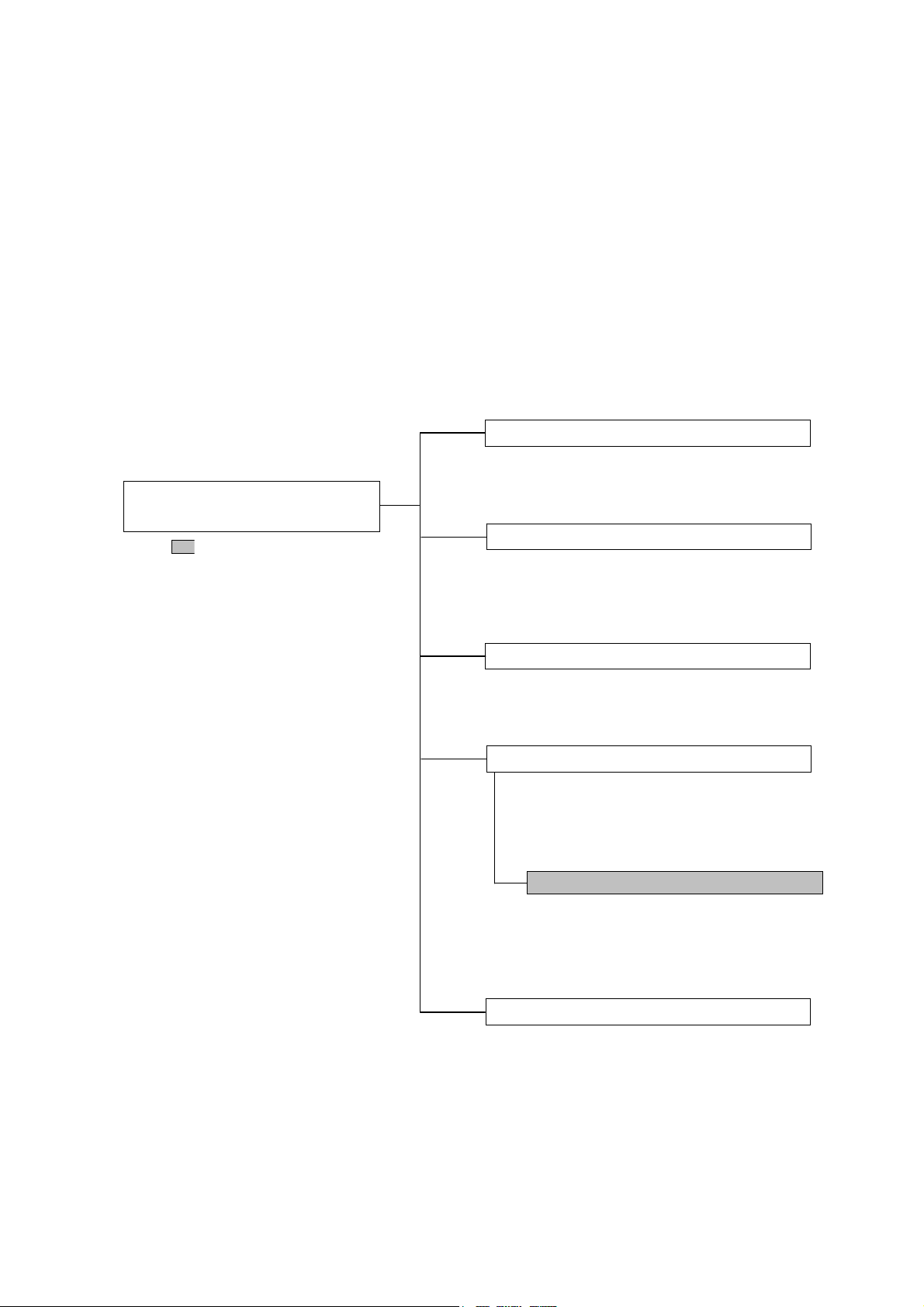
Configuration of Signal Quality
Analyzer Series Operation Manual
indicates this document.
About This Manual
A testing system combining an MP1800A Signal Quality Analyzer or
MT1810A 4 Slot Chassis mainframe, module(s), and control software is
called a Signal Quality Analyzer Series. The operation manuals of the
Signal Quality Analyzer Series consist of separate documents for the
installation guide, the mainframe, remote control operation, module(s),
and control software, as shown below.
Installation Guide
Installation guide from module installation
to the start of use. The Installation Guide
varies depending on the mainframe used.
Mainframe Operation Manual
Describes basic operations of the
mainframe. The Mainframe Operation
Manual varies depending on the mainframe
used.
Remote Control Operation Manual
Describes remote control using the GPIB
interface and LAN interface.
Module Operation Manual
Operation manual for the module. The
Module Operation Manual varies
depending on the module(s) used.
MP1861A 56G/64Gbit/s MUX
Describes how the
as well as how to operate and maintain it.
Control Software Operation Manual
Operation manual of the software that
controls the Signal Quality Analyzer Series.
MP1861A
is configured
I

Table of Contents
For Safety .................................................... iii
About This Manual........................................ I
Chapter 1 Overview ........................................... 1-1
1.1 Product Overview ......................................................... 1-2
1.2 Product Composition .................................................... 1-3
1.3 Specifications ................................................................ 1-6
Chapter 2 Before Use ........................................ 2-1
2.1 Preparation Before Use ................................................ 2-2
2.2 Getting Started with MX180000A ............................... 2-10
2.3 Other Usage Methods ................................................. 2-19
2.4 Preventing Damage .................................................... 2-24
Chapter 3 Panel Layout and Connectors ........ 3-1
3.1 Panel Layout ................................................................. 3-2
3.2 Inter-Module Connection .............................................. 3-5
Chapter 4 Window Operations ......................... 4-1
4.1 Configuration of Operation Screen ............................... 4-2
4.2 Configuration of the Operation Window ........................ 4-3
4.3 Setting Output Interface ................................................ 4-4
4.4 Operating the Linked Module ...................................... 4-13
4.5 Multi Channel Functions ............................................. 4-15
II
Chapter 5 Use Examples ................................... 5-1
5.1 Achieving Error-Free Data Transmission ..................... 5-2
5.2 Measuring Optical Transceiver Module ........................ 5-4
5.3 Testing Jitter Tolerance ................................................ 5-6

1
Chapter 6 Performance Test ............................. 6-1
6.1 Overview ....................................................................... 6-2
6.2 Devices Required for Performance Tests ..................... 6-3
6.3 Performance Test Items ............................................... 6-4
Chapter 7 Remote Commands ......................... 7-1
7.1 Status Commands ........................................................ 7-2
7.2 Common Commands .................................................... 7-5
7.3 64G MUX Commands ................................................. 7-15
Chapter 8 Maintenance ..................................... 8-1
8.1 Daily Maintenance ........................................................ 8-2
8.2 Cautions on Storage ..................................................... 8-2
8.3 Transportation ............................................................... 8-3
8.4 Calibration ..................................................................... 8-3
8.5 Disposal ........................................................................ 8-4
Chapter 9 Troubleshooting ............................... 9-1
9.1 Problems That May Occur When Starting MP1861A ... 9-2
9.2 Problems That May Occur During Output Waveform
Observation ................................................................... 9-3
9.3 Problems That May Occur During Error Rate
Measurement ................................................................ 9-4
2
3
4
5
6
7
8
9
III
Appendix

Appendix A List of Initial Settings .................. A-1
Appendix B Setting Restrictions ................. B-1
Appendix C Performance Test Record Sheet C-1
Appendix D Fault Diagnosis Tool ................... D-1
Appendix E Sequence Examples ..................... E-1
IV.

Chapter 1
This chapter provides an overview of the MP1861A 56G/64Gbit/s MUX
(MP1861A hereafter).
Product Overview ......................................................... 1-2
1.1
1.2 Product Composition .................................................... 1-3
1.2.1 Standard composition ....................................... 1-3
1.2.2 Options ............................................................. 1-4
1.2.3 Application parts ............................................... 1-5
1.3 Specifications ................................................................ 1-6
1.3.1 Specifications for MP1861A ............................. 1-6
Overview
1
Overview
1-1

Chapter 1 Overview
1.1 Product Overview
The MP1861A is a plug-in module that can be built into a Signal Quality
Analyzer main frame. This equipment 2:1 multiplexes the output signal
of the MU183020A 32 Gbit/s and MU181021A 32 Gbit/s 4ch PPG
(hereafter MU18302xA) to generate 8 to 64.2 Gbit/s PRBS, DATA and
Zero-Substitution patterns.
Various option configurations are available for the MP1861A. This
module is therefore useful for research, development, and production of
various types of digital communication equipment, modules, and devices.
Features of the MP1861A:
Operating rates: 8 to 56.2 Gbit/s (64.2 Gbit/s using additional options)
Multiplexes input data signal to 2:1
High-quality output signal waveform
Flexible for functional expansion in the future, by installing additional
options.
Controlled by MX180000A Signal Quality Analyzer Control Software
(hereafter MX180000A) when either MP1800A or controller PC
connected
1-2
1.2 Product Composition
1.2 Product Composition
1.2.1 Standard composition
Table 1.2.1-1 shows the standard composition of the MP1861A.
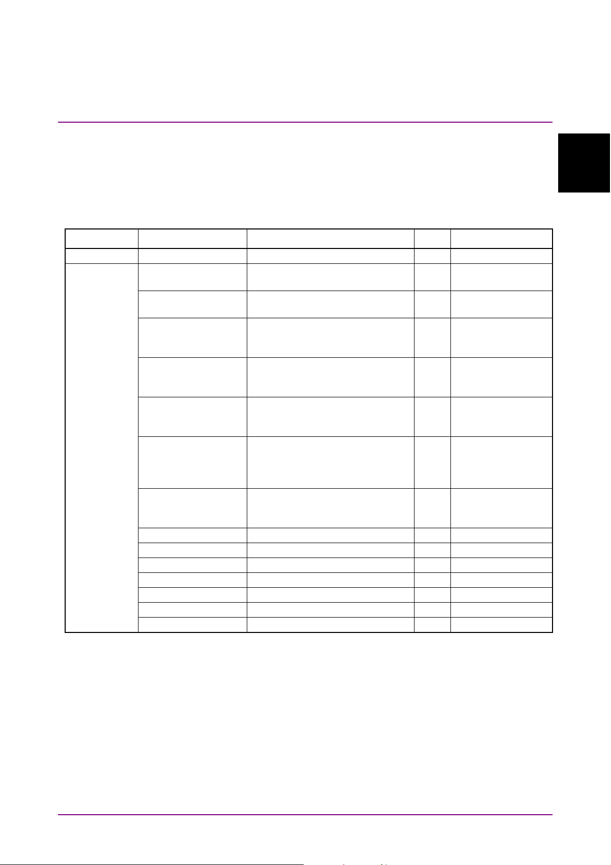
Table 1.2.1-1 Standard composition for MP1861A
Item Model Product name Q’ty Remarks
Main frame MP1861A 56G/64Gbit/s MUX 1
Accessory J1658A Coaxial skew match pair cable
(1.3 m, K connector)
J1652A Coaxial cable
(0.5 m, K connector)
J1654A U Link Cable B 1 Delayed Clock
J1363A Protection cap 2 Data
41V-6 Precision fixed attenuator 6 dB 2 Data
J1632A Terminator 4 Clock Output1/2
J1341A Open 3 External Clock
J1655A Semi-rigid Cable (0.2 m, V) 1
J1475A USB cable 1
Z1312A AC Adapter 1
G0342A ESD Discharger 1
Power cord 2.6 m 1
Z0897A MP1800A Manual CD 1 CD-ROM version
Z0918A MX180000A Software CD 1 CD-ROM version
1
Overview
1 Data Input1/2
1 External Clock
Input
Output to Mux
Clock Input
Output/XData
Output
Output/XData
Output
1/2 Clock
OutputBuffered
Clock Output
Input
Data Input1/2
1-3
A
Chapter 1 Overview
1.2.2 Options
Table 1.2.2-1 shows the options for the MP1861A. All options are sold
separately.
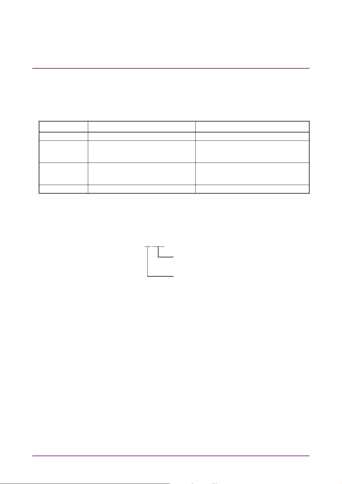
Table 1.2.2-1 Options for MP1861A
Model name Product name Remarks
MP1861A-x01 64 Gbit/s Extension
MP1861A-x11 Variable Data Output (0.5 to 2.5 Vp-p) Mandatory option
Cannot be installed together with
MP1861A-x13.
MP1861A-x13 Variable Data Output (0.5 to 3.5 Vp-p) Mandatory options
Cannot be installed together with
MP1861A-x11.
MP1861A-x30 Variable Data Delay
Option name format is as follows:
MP1861A- x x x
Indicates function.
This value is recognized by the mainframe.
nritsu management number.
This value is not recognized by the mainframe.
1-4

1.2.3 Application parts
Table 1.2.3-1 shows the application parts for the MP1861A. All
application parts are sold separately.
1.2 Product Composition
1
Table 1.2.3-1 Application parts
Model Product name Remarks
J1600A Skew match pair cable
(0.2 m, V connector)
J1656A Coaxial cable set
(MP1861A-MP1862A)
J1646A Passive Equalizer 6dB (V connector)
Z0306A Wrist strap
J1678A ESD Protection Adapter-K K connector
J1679A ESD Protection Adapter-V V connector
Cable for measurement
Two (a pair) for jitter tolerance
measurement
Overview
1-5
Chapter 1 Overview
1.3 Specifications
1.3.1 Specifications for MP1861A
The input/output specification value is defined assuming that a sampling
oscilloscope range with 70 GHz is used.
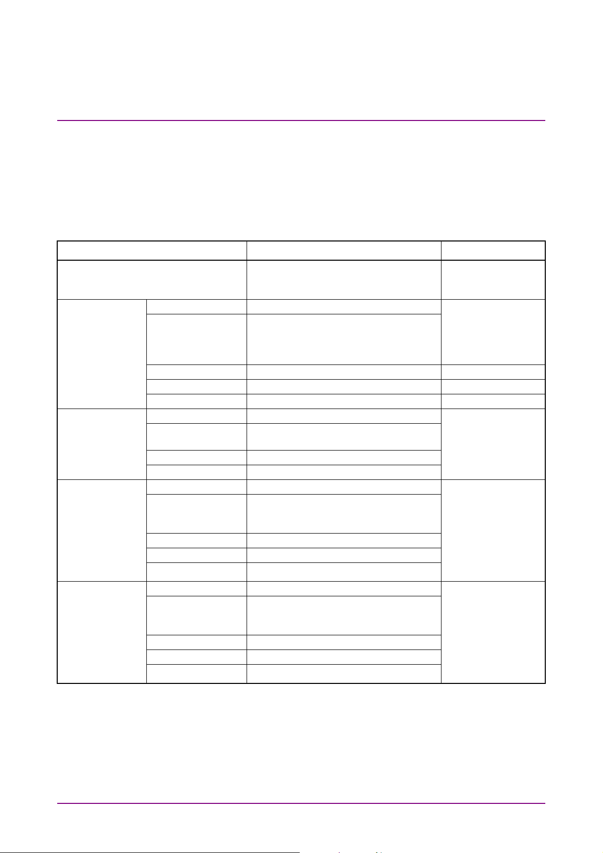
Table 1.3.1-1 Specifications for MP1861A
Item Specifications Remarks
Operating Bit Rate 8 to 56.2 Gbit/s
8 to 64.2 Gbit/s (when MP1861A-x01
installed)
External Clock
Input
Data Input Number of Input 2 (Data Input 1, Data Input 2) From MU18302xA
1/2 Clock Output Number of Output 1 (1/2 Clk Output) To be terminated
Clock Output Number of Output 2 (Clk Output1, Clk Output2) Output frequency:
Number of Input 1 (Ext Clk Input) From the
Frequency 4 to 28.1 GHz
4 to 32.1 GHz (when MP1861A-x01
installed)
Input Amplitude 0.3 to 1.0 Vp-p
Termination 50
Connector K (f.)
Level 0/–0.7 V (H:–0.15 to +0.05, L: –0.85 to
Termination 50
Connector K (f.)
Frequency 2 to 14.05 GHz
Output Amplitude 0.3 to 1.0 Vp-p
Termination 50
Connector SMA(f.)
Frequency 4 to 28.1 GHz
Output Amplitude 0.4 to 1.0 Vp-p
Termination 50
Connector K (f.)
/AC
–0.55)
/GND
2 to 16.05 GHz (when MP1861A-x01
installed)
/AC
4 to 32.1 GHz (when MP1861A-x01
installed)
/AC
MU18302xA Clock
Output connector
(Full rate Clock
Output setting)
Data Output
into 50 when not
in use.
Output frequency:
Half of the
frequency input to
the Ext Clk Input
connector.
The same as the
frequency input to
the Ext Clk Input
connector.
To the MP1862A
Ext. Clock Input
connector or DUT
1-6
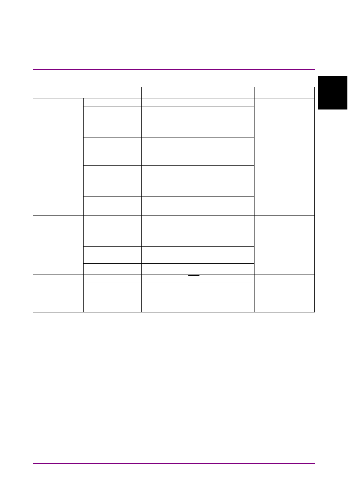
Table 1.3.1-1 Specifications for MP1861A (Cont’d)
1.3 Specifications
Buffered Clock
Output
Delayed Clock
Output
MUX Clock
Input
Data Output*1
MP1861A-x11
(Variable Data
Output (0.5 to
2.5 Vp-p))
Item Specifications Remarks
Number of Output 1 (Buffered Clk Output) To be terminated
Frequency 4 to 28.1 GHz
4 to 32.1 GHz (when MP1861A-x01
installed)
Output Amplitude 0.2 to 1.0 Vp-p
Termination 50
Connector K (f.)
Number of Output 1 (Delayed Clk Output) To be connected to
Frequency 4 to 28.1 GHz
Output Amplitude 0.2 to 1.0 Vp-p
Termination 50
Connector K (f.)
Number of Input 1 (MUX Clk Input) To be connected to
Frequency 4 to 28.1 GHz
Input Amplitude 0.2 to 1.0 Vp-p
Termination 50
Connector K (f.)
Number of Output 2 (Data Output/
Bit Rate 8 to 56.2 Gbit/s
/AC
4 to 32.1 GHz (when MP1861A-x01
installed)
/AC
4 to 32.1 GHz (when MP1861A-x01
installed)
/AC
Output)
Data
8 to 64.2 Gbit/s (when MP1861A-x01
installed)
into 50 when not
in use.
Output frequency:
The same as the
frequency input to
the Ext Clk Input
connector.
the Mux Clk Input
connector.
Output frequency:
The same as the
frequency input to
the Ext Clk Input
connector.
the Delayed Clk
Output connector.
Input frequency:
The same as the
frequency input to
the Ext Clk Input
connector.
1
Overview
*1: Defined under the following test pattern conditions:
• PRBS2^31–1
• Mark Ratio1/2
1-7

Chapter 1 Overview
Item Specifications Remarks
Data Output*1
Amplitude*
MP1861A-x11
(Variable Data
Output (0.5 to
2.5 Vp-p))
(Continued)
Offset –2.0 to +3.3 Voh /1 mV Step
Defined Interface NECL, SCFL, NCML, PCML, LVPECL
Cross Point 45% to 55% / 0.1% Step (≤56.2 Gbit/s)
Tr/Tf*2, *3 Typ.8 ps (20 to 80%)*4,*5
Half Period Jitter –20 to 20/1 Step
Jitter (RMS)*2, *3 Typ. 450 fs, ≤550 fs*4,*7
Random Jitter
(RMS)
Waveform
Distortion
(0-peak)*
ON•OFF Can be switched ON/OFF
Termination Can be switched between AC and DC, 50
Connector V (f.)
Offset reference Can be switched between Voh, Vth and
Data/XData
Tracking
Level Guard Yes
Table 1.3.1-1 Specifications for MP1861A (Cont’d)
2, *3
0.5 to 2.5 Vp-p/2 mV Step
0.5 to 2.5 Vp-p/2 mV Step (≤56.2 Gbit/s) *
1.0 to 2.5 Vp-p/2 mV Step (>56.2 Gbit/s)
The range of 0.5 to 0.998 V is not
guaranteed but can be set.
*5
Accuracy: 50 mV 17% of Amplitude*4,*5
Min. –4.0 Vol
Accuracy:
65 mV 10% of Offset (Vth)
(Amplitude Accuracy/2)
Current Limit:
Sourcing 100 mA/Sinking 100 mA
“Overload” is displayed in the following
cases because the cross point of 50 %
cannot be guaranteed.
• >56.2 Gbit/s
• When MP1861A-x01 is installed
With monitor display in units of UI.
Typ. 650 fs *
5,*7
Typ. 200 fs *4,*7
4,*5,*6
2,*3
Typ. 25 mV 10% of Amplitude *
/GND, –2 V, + 1.3 V (when DC selected)
Vol
Yes
Data and
5
can be set
separately.
Data
1-8
External ATT
Factor
*2: Defined based on the condition the cross point is 50%.
Yes Data and
Data
can be set
separately.

1.3 Specifications
*3: Defined based on the following observation conditions:
• The coaxial cable (J1655A) is used
• The sampling oscilloscope band is 70 GHz.
1
*4: At a bit rate of 56.2 Gbit/s
*5: At a bit rate of 64.2 Gbit/s (with MP1861A-x01 installed)
*6: At an output amplitude of 2.5 Vp-p
*7: The specified value applies when using an oscilloscope with residual
jitter of less than 200 fs (RMS).
Overview
1-9
Chapter 1 Overview
Item Specifications Remarks
Table 1.3.1-1 Specifications for MP1861A (Cont’d)
Data Output*1
(Cont’d)
MP1861A-x13
(Variable
Data Output
(0.5 to
3.5 Vp-p))
Number of Output 2 (Data Output /
Output)
Data
Bit Rate 8 to 56.2 Gbit/s
8 to 64.2 Gbit/s (when MP1861A-x01
installed)
*5
Data and
can be set
separately.
Data
Amplitude*2, *3 0.5 to 3.5 Vp-p/2 mV Step
0.5 to 3.5 Vp-p/2 mV Step (≤56.2 Gbit/s)
1.0 to 3.5 Vp-p/2 mV Step (>56.2 Gbit/s)
The range of 0.5 to 0.998 V is not
5
guaranteed but can be set.*
Accuracy: 50 mV 17% of Amplitude*3
Offset –2.0 to + 3.3 Voh/1 mV Step
Min. –4.0 Vol
Accuracy:
65 mV 10% of Offset (Vth)
(Amplitude Accuracy/2)
Current Limit:
Sourcing 100 mA/Sinking 100 mA
Defined Interface NECL, SCFL, NCML, PCML, LVPECL
Cross Point 45 to 55% /0.1% Step (≤56.2 Gbit/s)
“Overload” is displayed in the following
cases because the cross point of 50 %
cannot be guaranteed.
• >56.2 Gbit/s
• When MP1861A-x01 is installed
Tr/Tf*2,*3 Typ.8 ps (20 to 80%)*4,*5
Half Period Jitter –20 to 20/1 Step
With monitor display in units of UI.
Jitter (RMS)*2,*3 Typ. 450 fs, ≤550 fs*4, *
7
Typ. 650 fs, *5, *7
Random Jitter
Typ. 200fs *4, *7
(RMS)
Waveform Distortion
2,*3
(0-peak) *
Typ. 25 mV 10% of Amplitude *
4,*5,*6
ON/OFF Can be switched ON/OFF
Termination Can be switched between AC and DC,
50 /GND, –2 V, + 1.3 V (when DC
selected)
Connector V (f.)
Offset reference Can be switched between Voh, Vth and Vol
1-10
Data/XData
Yes
Tracking
Level Guard Yes
External ATT
Yes Data and
Factor
can be set
separately.
Data

Table 1.3.1-1 Specifications for MP1861A (Cont'd)
1.3 Specifications
Jitter tolerance
1,*4,*5
*
Item Specifications Remarks
When interacting
with MU181500B+
MU18302xA
This item is defined under the following
conditions:
• Bit rate:
1
Overview
56.2 Gbit/s
64.2 Gbit/s (With MP1861A-x01 installed)
• Pattern: PRBS2^31–1
• Temperature: 20 to 30°C
• Loopback connection with MP1862A
The following shall be applied simultaneously
by using MU181500B:
• SSC with a 5300 ppm amplitude
• RJ of 0.3 UI
Modulation frequency:
56.2 Gbit/s: Up to 250 MHz
64.2 Gbit/s: Up to 150 MHz
2000
20dB/decade
15
10
Variable Data
Delay
Jitter Amplitude [UIp-p]
Modulation Frequency [MHz]
Variable phase
–64000 to +64000 mUI/ 4 mUI Step With
range
Phase setting
error
Typ. 50 mUIp-p (≤56.2 Gbit/s) *
Typ. ±150 mUIp-p (>56.2Gbit/s, (when
MP1861A-x01 installed)) *
8
8
mUI-ps conversion Available
Calibration Available (When jitter modulation is off)
Relative 0 Available
Jitter Input Available
*8: The values are specified, assuming an oscilloscope with a linearity of
less than 200 fs will be used.
MP1861A-x30
installed
1-11

Chapter 1 Overview
Table 1.3.1-1 Specifications for MP1861A (Cont'd)
Item Specifications Remarks
Control interface USB 2.0 or 1.1 Type B ×1
Channel setting Can be selected from CH1 to CH4.
Power (AC
adapter)
Power consumption DC 19 V, 4 A
Dimensions
(Excluding protrusions)
Mass 5.0 kg or less
Environmental
Performance
Input voltage AC 100 to 240 V *9
Input frequency 50 to 60 Hz
Output power DC 19 V, 7.9 A (Max)
90.9 mm(H), 120 mm (W), 140 mm (D)
Operation
Temperature
Storage
Temperature
*9: Operating voltage: within the range of +10% to –15% from the rated
+ 15 to + 35C (ambient temperature of
equipment)
–20 to +60C
voltage
1-12.

2-1
Before Use
Chapter 2 Before Use
This chapter describes preparation required before using MP1861A.
Preparation Before Use ................................................ 2-2
2.1
2.1.1 Environmental Conditions of Installation Site ... 2-2
2.1.2 Clearance from Fan .......................................... 2-2
2.1.3 Power Connection ............................................ 2-3
2.1.4 Usage Patterns of MP1861A ............................ 2-4
2.2 Getting Started with MX180000A ............................... 2-10
2.2.1 Installing MX180000A..................................... 2-10
2.2.2 Starting MX180000A ...................................... 2-15
2.2.3 Exiting MX180000A ........................................ 2-16
2.2.4 Messages that are displayed when
connecting/disconnecting the USB cable ....... 2-17
2.3 Other Usage Methods ................................................. 2-19
2.3.1 Checking Installed Software Version .............. 2-19
2.3.2 Updating Software .......................................... 2-21
2.3.3 Initializing Settings .......................................... 2-23
2.4 Preventing Damage .................................................... 2-24
2

Chapter 2 Before Use
2-2
10 cm
10 cm
2.1 Preparation Before Use
This section explains the installation position of the mainframe and how
to turn on the power.
2.1.1 Environmental Conditions of Installation Site
The MP1861A operates in the temperature range from 15 to 35°C. Avoid
using it under any of the following environment conditions that may
cause failure.
•
Strong vibrations
•
High humidity or dust
•
Direct sunlight
•
Chemically active gases
•
Substantial temperature changes
Note:
Condensation may form inside of the MP1861A if it is moved to a
warm location after operating for a long time in a cool location. In
such a case, be sure to wait until the MP1861A becomes completely
dry before turning on the power. Doing so with condensation
present may cause a short circuit and damage the MP1861A.
2.1.2 Clearance from Fan
A cooling fan is provided on the side of the MP1861A. Install the
MP1861A at least 10 cm away from walls, peripheral devices, or the like
to prevent blockage of ventilation. Insufficient ventilation may cause the
internal temperature to rise, resulting in failure.
Figure 2.1.2-1 Clearance from fan

2.1 Preparation Before Use
2-3
Before Use
2.1.3 Power Connection
This section describes the procedures for supplying power.
Use a supplied AC adapter. If AC adapter other than the supplied one is
used, the MP1861A may be damaged.
Connect the shielded connector from the AC adapter to the rear panel
connector of the MP1861A. Refer to Figure 2.1.3-1.
Figure 2.1.3-1 Rear Panel of MP1861A
Insert the power plug into an outlet, and connect the other end to the
power inlet on the rear panel. To ensure that the instrument is earthed,
always use the supplied 3-pin power cord, and insert the plug into an
outlet with an earth terminal.
2
WARNING
If the power cord is connected without grounding
MP1861A, there is a risk of receiving a fatal electric shock.
In addition, the peripheral devices connected to MP1861A
may be damaged.
When connecting to the power supply, DO NOT connect to
an outlet without a ground terminal. Also, avoid using
electrical equipment such as an extension cord or a
transformer.

Chapter 2 Before Use
2-4
MP1800A with MX180000A
MP186xA
USB
Power
Data OutputData Output
Clock Output1/2 Clock Output
0.7Vp-p 0.7Vp-p
0.5-3.5Vp-p
On
USB Connection
2.1.4 Usage Patterns of MP1861A
This section describes the two ways to control MP1861A and how to
connect to MP1800A or control PC.
MP1861A is controlled via the MX180000A installed to MP1800A or
control PC. When connecting MP1861A to MP1800A (control PC), use the
standard accessory USB cable.
(1) Connecting MP1800A:
Connect the USB connector (type A) to the front panel or rear panel
of MP1800A, and then connect the USB connector (type B) to
MP1861A.
Figure 2.1.4-1 Connecting to MP1800A
To connect two MP1861As to MP1800A, connect them to the USB
connectors (type A) on MP1800A’s front panel.
MP1861As may not be able to function properly if one of them is
connected to the USB connector on MP1800’s rear panel. To connect
more than two MP1861As, connect a USB hub to the front or rear
panel of MP1800A, and then connect each of MP1861As to MP1800A
via the USB hub.

2.1 Preparation Before Use
2-5
Before Use
Figure 2.1.4-2 Connecting Multiple MP186xAs to MP1800A
2

Chapter 2 Before Use
2-6
MP1825B
USB
MP186xA
Control PC with MX180000A
(2) Connecting to control PC:
Connect the USB connector (type A) to PC, and then connect the
USB connector (type B) to the MP1861A.
Figure 2.1.4-3 Connecting to Control PC
Note the following when connecting two MP186xAs to control PC:
For PC with multiple USB connectors, connect to the USB
•
connector with the same USB controller, as shown below.
It may not function normally if connecting to the connector with
different USB controller.
If the number of USB connectors on the Control PC is not
•
enough, use a USB hub.
Note:
Anritsu is not responsible for the proper functioning of all USB
hubs.

2.1 Preparation Before Use
2-7
Before Use
MP186xA
MP186xA
Control PC with MX180000A
Control PC with MX180000A
USB connector
with
controller
USB
USB connector
with
the same
controller
USB connector
of the same
controller
MP186xA
Control PC with MX180000A
USB Hub
USB
different
2
Figure 2.1.4-4 Connecting Control PC to Two MP186xAs
Figure 2.1.4-5 Connecting Control PC Using A USB Hub
Using other USB devices
Refer to the following for how to use commercially available USB devices
when MP1861A is in use.
Connect the USB device before starting the MP1800A; do not connect or
disconnect USB devices while using the MX180000A Control Software.
In addition, only read measurement data using a USB device after
exiting the MX180000A Control Software (closing selector screen).

Chapter 2 Before Use
2-8
Compatibility
IBM-PC or compatible PC
OS
Windows XP Version 2002 Service Pack 2
Hard Disk
Required free disk space for installing the software
package: At least 200 MB
CPU Pentium4 processer and 1.6 GHz or higher
Memory ≥ 512 MB
Monitor resolution 800 × 600 dots or more
Display color ≥ 256 colors
CD-ROM driver Required when installing the software package
USB Interface USB 2.0 or USB 1.1
Use a PC that meets or exceeds the following specifications.
Table 2.1.4-1 Required Specifications for Control PC (For Windows XP)
Item Specifications

2.1 Preparation Before Use
2-9
Before Use
Compatibility
IBM-PC or compatible PC
CPU
OS
Windows 7 Professional/Enterprise/Ultimate
Memory
32-bit: 1 GB RAM
64-bit: 2 GB RAM
CD-ROM driver
Required when installing the software package
Hard Disk
Required free disk space for installing the software
package: At least 200 MB
USB Interface
10 BASE-T or 100 BASE-TX
Table 2.1.4-2 Required Specifications for Control PC (For Windows 7)
Item Specifications
1 GHz or faster 32-bit (x86) or 64-bit (x64) processor
2
Monitor resolution 800 × 600 dots or more
Display color ≥ 256 colors
The MP1861A will not operate normally when performing the following
operations and functions on the PC while the MX180000A is operating.
(1) Running another application at same time
(2) Closing lid of laptop PC
(3) Running screen saver
(4) Running battery save function
Read the PC instruction manual to switch off the screen saver and
battery save functions described in items (3) and (4) above.
Note:
Operation is not assured even with PCs meeting the specifications
outlined in Table 2.1.4-1 or Table 2.1.4-2.

Chapter 2 Before Use
2-10
Yes
Yes
Continue Anyway
2.2 Getting Started with MX180000A
This section explains how to install the software and how to start and
exit MX180000A.
2.2.1 Installing MX180000A
Note the following procedure when installing software for the MP1861A
in the MP1800A or remote PC.
The following examples show the case when the software is installed in
the MP1800A. For the general software installation procedures, refer to
the
MP1800A Installation Guide (W2747AE)
Guide (W2748AE)
(1) When the general procedures are followed by the installer, the
confirmation dialog is displayed. Press
.
or
MT1810A Installation
to start installation.
Figure 2.2.1-1 Confirmation Dialog of USB Driver Installation (1)
(2) For Windows 7, a confirmation dialog box is displayed to ask if you
want to install Anritsu Corporation Universal Serial BUS Controller.
Click
to continue installation.
Click
to continue installation.

2.2 Getting Started with MX180000A
2-11
Before Use
Continue Anyway
Finish
(3) For Windows XP, when the screen shown in Figure 2.2.1-2 is
displayed, click
to continue.
2
Figure 2.2.1-2 Confirmation Dialog of USB Driver Installation (2)
Note:
The screen as shown in Figure 2.2.1-1 may not be displayed on the
front page. If software installations take a long time, check that
the screen as shown in Figure 2.2.1-1 is hidden at the back of the
other screen.
(4) The following window is displayed when the installation completes
normally. Click
to end the installation procedure.
Figure 2.2.1-3 Completing Installation

Chapter 2 Before Use
2-12
No, not this time
Next
Install the software automatically
Next
When the MP1861A is connected to the MP1800A or remote PC after
software installation, install the driver using the following procedures.
The following example show when the MP1861A is connected to the
MP1800A.
(1) Connect the MP1800A and MP1861A using an USB cable.
For Windows 7, the driver is installed automatically.
For Windows XP, perform the step 2 to 5 to install the driver.
(2) The Found New Hardware Wizard screen is displayed to confirm
windows update. Select
and press
.
(3) Select
Figure 2.2.1-4 Confirmation of Windows Update
Figure 2.2.1-5 Software Installation
and press
.

2.2 Getting Started with MX180000A
2-13
Before Use
Continue Anyway
Finish
(4) Figure 2.2.1-6 is displayed when the hardware is found.
Press
to continue the installation procedures.
2
(5) Click
Figure 2.2.1-6 Hardware Installation
to end the installation procedure.
Figure 2.2.1-7 Completing Installation

Chapter 2 Before Use
2-14
Start
Add/Remove Programs
Anritsu USB Device Driver
Remove
If the installed driver is no longer needed, uninstall it as follows.
(1) Select
Panel.
(2) Double-click
(3) Select
start the uninstallation.
menu →Control Panel
Figure 2.2.1-8 Removing USB Driver
, and then open the Control
in the Control Panel.
from the list and click
to

2.2 Getting Started with MX180000A
2-15
Before Use
2.2.2 Starting MX180000A
When connecting to MP1800A:
(1) Connect the MP1861A and MP1800A as explained in Section 2.1.4.
(2) Connect the AC adapter to the MP1861A and set the power switch to
ON.
The LED lights green while power is on.
(3) When the MP1800A is turned on, Windows boots and the
MX180000A starts automatically. Select [Main application] on the
selector screen.
(4) The MP1861A control screen is displayed.
When connecting to control PC:
2
(1) Connect the MP1861A and control PC as explained in Section 2.1.4.
(2) Connect the AC adapter to the MP1861A and set the power switch to
ON.
The LED lights green while power is on.
(3) Start the MX180000A controller PC and select Main application on
the selector screen.
(4) The MP1861A control screen is displayed.
Figure 2.2.2-1 Selector Screen

Chapter 2 Before Use
2-16
Main application
Exit
OFF
2.2.3 Exiting MX180000A
When connecting to MP1800A:
(1) Press and hold the power switch on the MP1800A front panel or
click the Shut down button on the selector screen. After the
application are shut down, the MP18000A Power lamp goes off, and
then the Standby LED lights up.
(2) Set the MP1861A power switch to OFF.
The LED lights orange, indicating the standby status.
When connecting to control PC:
(1) Close
(2) Press
(3) Set the MP1861A power switch to
Notes:
on the selector screen to close the window.
The LED lights orange, indicating the standby status.
To cut the power without following the above procedure, press
•
the MP1861A power switch for more than 10 seconds to enter
the standby status.
Do not disconnect the power cord and AC adapter without first
•
turning off the MP1861A as described above, otherwise the
MP1861A may be damaged.
to display the selector screen.
.

2.2 Getting Started with MX180000A
2-17
Before Use
2.2.4 Messages that are displayed when connecting/disconnecting the
USB cable
This section describes the messages that are displayed when the USB
cable is connected to or disconnected from MP1861A.
When disconnecting the USB connection of this equipment for some
unexpected reason, follow the procedure described below to minimize the
impact on running applications. However, all the USB disconnection
cannot be assured by this operation. Normally, follow the startup and
shutdown procedures described in sections 2.2.2 and 2.2.3, respectively.
When USB connection disconnected while application running:
(1) The following dialog screen is displayed when the USB connection is
disconnected.
Figure 2.2.4-1 USB Disconnected
(2) The buttons for calling screens are disabled and the screen goes
blank. The Data Output and Clock Output are set forcibly to OFF.
2
(3) The MP1800A module connected to this equipment can still be used.
When USB device connected while application running:
(1) The following USB connection dialog is displayed.
Figure 2.2.4-2 USB Connection Message

Chapter 2 Before Use
2-18
(2) If there is a backup file (saved when previous application terminated
when connection made), each setting is restored. Each setting is
restored when reconnecting previously connected equipment that
has been disconnected.
(3) The button for calling screens is enabled and the screen is displayed
for use. The Data Output and Clock Output are OFF.
When USB connection disconnected while using Setup utility:
(1) No warning is issued at the instant of disconnection.
(2) If processing is executed when the equipment is already
disconnected, a message indicating that the equipment is not
connected is displayed.
Figure 2.2.4-3 USB Disconnection Message
while Setup Utility in Use
(3) The MP1800A module connected to this equipment can still be used.
When USB device connected while using Setup utility:
(1) When a connection is made while using the Setup utility, the
equipment is not recognized.
(2) Restart from the selector screen after setting the power OFF and ON
and running the Setup utility once more.
CAUTION
If the connection between MP1861A, MP1800A and
controller PC is broken during downloading with the Setup
utility, MP1861A may no longer operate normally. NEVER
break the connection during downloading.

2.3 Other Usage Methods
2-19
Before Use
2.3 Other Usage Methods
Help
Versi on
Help
Setup utility
Login
User
Version
This section explains how to check the installed software version,
perform software updates, and initialize the settings.
For how to operate the MX180000A, refer to the
Quality Analyzer Control Software Operation Manual
2.3.1 Checking Installed Software Version
Check the installed software version using the
Application menu bar or the Setup utility.
Select
following screen opens to display the currently installed software version.
from the
item at the Main Application menu bar. The
MX180000A Signal
.
item at the Main
2
Figure 2.3.1-1 Version Display Screen
Objects displayed with yellow highlighting on the Version Display screen
have a version other than the installed version. In this case, update the
installed software as described in section 2.3.2. If the installed software
versions are mismatched, operation may not be normal.
The Setup utility is selected by choosing
screen displayed when the MX180000A is started; log-in using
.
Click the
below opens to display the version information.
tab to display the software version. The screen shown
from the selector
–

Chapter 2 Before Use
2-20
Figure 2.3.1-2 Version Display Screen
Objects displayed with yellow highlighting on the Version Display screen
have a version other than the installed version. In this case, update the
installed software as described in section 2.3.2. If the installed software
versions are mismatched, operation may not be normal.

2.3 Other Usage Methods
2-21
Before Use
2.3.2 Updating Software
Download
Load
Load
The equipment software can be updated from the Setup utility screen.
When installing a new software version, there may sometimes be a
mismatch with already installed software and operation is not assured.
To solve the problem of mismatched installed software versions, start the
Setup utility and click the
the downloaded file display field. Put checkmarks in the boxes opposite
the files to be upgraded and click the
When download is completed normally, the installed software can be
upgraded.
Normally, the installed software is upgraded to the latest version when
the
button is clicked.
tab to display the download files in
button to start the download.
2
Figure 2.3.2-1 Download Screen

Chapter 2 Before Use
2-22
[1]
This displays files that can be downloaded
checkmarks in the boxes and download the new files.
[2]
These are checkboxes for files to download. When it is necessary to download
versions), the checkbox is marked automatically.
[3]
This executes download using the MX180000A SQA control software installer.
differences, the files are downloaded.
[4]
This displays the download slot number and file name.
[5]
This displays the download status.
[6]
This suspends downloading.
[7]
This quits the setup utility.
No. Function and Usage
Table 2.3.2-1 Download Screen
Versions displayed in the New column are versions of object files offered by the
MX180000A SQA control software.
Versions displayed in the Current column are the versions of software already
installed in the equipment.
If there is a mismatch between versions in New and Current, place
the latest version (because there are differences between the New and Current
The versions of files saved to the internal hard disk are compared with
versions to be downloaded for each module in this equipment, and if there are
Notes:
If the Current version is not displayed and there is no
•
checkmark in the checkbox, put a checkmark in the checkbox
and execute download.
Downloading the FPGA as described below takes about 10
•
minutes per file. The power must be toggled OFF and ON to
enable the update. Set the power to OFF as described in section
2.2.3.
xx in the filename MP186xA_MUX_Opt_Delay_xx_xx_xx.FPGA
indicates the version.
CAUTION
If the connection between MP1861A, MP1800A and
controller PC is broken during downloading with the Setup
utility, MP1861A may no longer operate normally. NEVER
break the connection during downloading.

2.3 Other Usage Methods
2-23
Before Use
2.3.3 Initializing Settings
Initialize
Help
Execute
Click
to initialize the equipment to the factory defaults. In addition, the
equipment settings can be returned to the factory defaults using the
Setup utility; start the utility and click the
in the File menu of the MX180000A SQA control software
tab.
2
Figure 2.3.3-1 Initializing Settings
When
initialized to the factory default settings.
in the Initialize group box is clicked, the equipment is

Chapter 2 Before Use
2-24
•
•
•
•
•
•
•
•
2.4 Preventing Damage
Be sure to observe the rating ranges when connecting input and output
of the MP1861A. Otherwise, the MP1861A may be damaged.
Do not apply a voltage exceeding the rated voltage of
MP1861A. Excessively high input voltage can damage
the circuit.
When output is used at the 50 Ω/GND terminator, never
feed any current or input signals to the output.
As an antistatic measure, make sure the other devices
(including experimental circuits) to be connected with
ground wires before connecting the I/O connectors.
CAUTION
The outer conductor and core of the coaxial cable may
become charged as a capacitor. Use any metal to
discharge the outer conductor and core before use.
Never open the MP1861A. If you open it and the
MP1861A has failed or sufficient performance cannot
be obtained, we may decline to repair the MP1861A.
The MP1861A has many important circuits and parts
including hybrid ICs. These parts are extremely
sensitive to static electric charges, so never open the
case of the MP1861A.
The hybrid ICs used in the MP1861A are sealed in
airtight containers; never open them. If you open it and
the MP1861A has failed or sufficient performance
cannot be obtained, we may decline to repair the
MP1861A.
To protect the MP1861A from e being damaged by
static electricity, be sure to observe the following:
• Spread a conductive sheet on a workbench.
• Wear a wrist strap connected to the conductive
sheet or the frame ground of MP1861A

2.4 Preventing Damage
2-25
Before Use
•
•
•
CAUTION
When connecting an external device such as a Bias-T
to the output connectors of this equipment (PPG or
MUX), if the output signal includes any DC voltage,
variations in the output of the DC power supply or load
may change the level of the output signal, risking
damage to the internal circuits. Note the following
precautions when using this equipment:
Do not connect or disconnect any external devices
while DC voltage is impressed.
Only switch DC power sources ON and OFF when all
equipment connections have been completed.
<Recommended procedure>
Measurement Preparation 1:
1. Connect all equipment.
2. Set the DC power supply output to ON.
3. Set the equipment output to ON and complete
measurement.
Measurement Preparation 2:
1. Set the equipment output to OFF.
2. Set the DC power supply output to OFF.
3. Disconnect the equipment, or change the DUT
connections.
Since even unforeseen fluctuations in DC voltage and
load (open or short circuits at the equipment output
side and changes caused by using a high-frequency
probe, etc.) can damage the DUT and equipment, we
recommend connecting a 50–ohm resistance in series
with the DC terminal of the Bias-T to prevent risk of
damage.
2

Chapter 2 Before Use
2-26.
MP1861A
DUT
DC
50Ω
Bias-T
Coaxial cable
Coaxial cable
Set output ON/OFF after
To protect DUT and PPG
Do not connect/disconnect while DC
power
voltage impressed.
Figure. 2.4-1 Bias-T Connection Example
completing connections.

Chapter 3
This chapter describes the panels and connectors of MP1861A.
3.1
3.2 Inter-Module Connection .............................................. 3-5
Panel Layout and Connectors
Panel Layout ................................................................. 3-2
3.1.1 MP1861A Front Panel ...................................... 3-2
3.1.2 MP1861A Rear Panel ....................................... 3-3
3.2.1 1ch TRx connection .......................................... 3-7
3.2.2 2ch Tx connection .......................................... 3-10
3
Panel Layout and Connectors
3-1

Chapter 3 Panel Layout and Connectors
3.1 Panel Layout
This section describes the components located on the front and rear
panels of MP1861A.
3.1.1 MP1861A Front Panel
[2]
[3]
[1]
[6]
Figure 3.1.1-1 MP1861A (Option-x13) Front Panel
Table 3.1.1-1 MP1861A Front Panel Name and Function
No. Name Description
[1] Data Output connector
Output connector
Data
[2] Clock Output 1 connector
Clock Output 2 connector
[3] USB Connection LED Displays status of connection between MP1861A and MP1800A
[4] Power Switch
[5] Channel number indicators
(LEDs)
[6] Frame ground To which connects a wrist strap for antistatic measures before
Output for 2:1 multiplexed differential data signal
Supports various interfaces by selecting option
Output for Clock signal for MP1862A
or control PC
The LED is lit when the MP1861A can be controlled.
Switches from ON to Standby
When AC adapter and power code are connected, the switch
LED lights orange in the Standby status and green at ON.
The lamp of the set channel number illuminates.
1: Blue, 2: Pink, 3: Purple, 4: Orange
Set the channel number with the Channel Setting switch on the
rear panel of MP1861A.
using MP1861A.
Always wear the wrist strap when using MP1861A.
[4]
[5]
3-2

3.1.2 MP1861A Rear Panel
3.1 Panel Layout
[7]
[2]
[10]
[1]
[5]
Figure 3.1.2-1 MP1861A Rear Panel
Table 3.1.2-1 MP1861A Rear Panel Name and Function
No. Name Description
[1] Data Input 1 connector
Data Input 2 connector
[2] Ext. Clock Input connector Connector for inputting the clock signal used as reference for
[3] Delayed Clock Output
connector
[4] Buffered Clock Output
connector
[5] 1/2 Clock Output connector Connector for outputting the frequency clock signal that is half of
[6] Mux Clock Input connector Connector for inputting the same frequency clock as the clock
[7] DC Input connector Connector for connecting AC adapter supplied as standard
[8] USB port Used for connecting MP1800A or controller PC to this equipment
Inputs for data signals from dual MU18302xA
Multiplexes signal to Data Output
equipment operation
Connector for outputting the same frequency clock as the clock
that is input to the Ext. Clock Input connector. Connect to the
MUX Clock Input connector using the supplied J1654A U-link
cable B.
Connector for outputting the same frequency clock as the clock
that is input to the Ext. Clock Input connector. Terminate into
50 when not in use.
the frequency clock input to the Ext. Clock Input connector.
Terminate into 50 when not in use.
that is input to the Ext. Clock Input connector. Connect to the
Delayed Clock Output connector using the supplied J1654A
U-link cable B.
accessory. Do not use non-Anritsu AC adapters, otherwise there
is a risk of damage to the equipment.
Do NOT connect anything other than the MP1800A or controller
PC.
[8]
[4]
[9]
[6]
[3]
3
Panel Layout and Connectors
3-3

Chapter 3 Panel Layout and Connectors
Table 3.1.2-1 MP1861A Rear Panel Name and Function (Cont’d)
No. Name Description
[9] Channel Setting switch Sets the channel number of MP1861A.
Channel Number Switch Setting
1 0,0,0
2 1,0,0
3 0,1,0
4 1,1,0
Make sure the power to MP1861A has been shut off before
changing the channel switch settings. The new channel number
setting is enabled when powering on the next time.
[10] Frame ground Connector for wrist strap to discharge static electricity
Always wear a wrist strap when using this equipment.
3-4

3.2 Inter-Module Connection
This section describes precautions to follow when handling the
equipment. Prevent the equipment from being damaged by static
electricity.
Do not apply a voltage exceeding the rated voltage of
MP1861A. Excessively high input voltage can damage
the circuit.
As an antistatic measure, make sure the other devices
(including experimental circuits) to be connected with
ground wires before connecting the I/O connectors.
3.2 Inter-Module Connection
WARNING
3
Panel Layout and Connectors
Be sure to discharge static electricity from the outer
conductors and cores of the coaxial cables by touching
them with any metal object before connecting the
coaxial cables.
To protect the MP1861A from e being damaged by
static electricity, be sure to observe the following:
• Spread a conductive sheet on a workbench.
• Wear a wrist strap connected to the conductive
sheet or the frame ground of MP1861A.
Do not apply excessive force to connectors when
removing the cables from MP1861A. Excessive force
can degrade the characteristics or cause failures.
Be sure to use a torque wrench when
connecting/disconnecting the cables. (Recommended
torque: 0.9 N-M)
3-5

Chapter 3 Panel Layout and Connectors
Avoid inputting the signal exceeding the maximum input
level of MP1861A when connecting the Data Output
connector of MU183020A/MU183021A to the Data Input1
and 2 connectors of MP1861A.
Maximum input level of the Data Input1 and 2 connectors
of MP1861A: 0/–0.7 V (Vth = –0.35V)
Maximum data output level:
• MU183020A-x13/x23, MU183021A-x13: 3.50 Vp-p
• MU183020A-x12/x22, MU183021A-x12: 2.50 Vp-p
The Data Input connector of MP1861A can be damaged if
the signal exceeding the maximum input level is input.
CAUTION
3-6

3.2.1 1ch TRx connection
This section describes a connection example using one MP1861A and one
MP1862A 56G/64G DEMUX (hereafter, MP1862A). According to the
following procedure, connect the equipment as shown in Figure 3.2.1-1.
[Equipment configuration]
MP1861A (this module)
MP1862A
MP1800A
MU183020A-x22/x23+x31
MU183040B
MU181500B
MU181000A
DUT (Device under test)
3.2 Inter-Module Connection
3
Panel Layout and Connectors
3-7

Chapter 3 Panel Layout and Connectors
[Procedure]
1. Connect the Clock Output connector of MU181000A and the Ext.
Clock Input connector of MU181500B by using the J1624A coaxial
cable that comes with MU181000A.
2. Connect the Jittered Clock Output connector of MU181500B and the
Ext. Clock Input connector of MU183020A by using the J1624A
coaxial cable that comes with MU181500B.
3. Connect the Data Input1/2 connectors on the rear panel of MP1861A
and the Data Output1/2 connectors of MU183020A respectively by
using coaxial cables. The coaxial cables must be one of the following:
• J1658A coaxial skew match pair cable that comes with MP1861A
• Coaxial cables that are of the same length
4. Connect the Clock Output connector of MU183020A and the Ext.
Clock Input connector on the rear panel of MP1861A by using the
J1652A coaxial cable that comes with MP1861A.
5. Connect the Buffered Clock Output and MUX Clock Input
connectors that are on the rear panel of MP1861A, by using the
J1653A cable that comes with MP1861A. If the MP1861A-x30
Variable Data Delay is installed to MP1861A, connect the Delayed
Clock Output and MUX Clock Input connectors that are on the rear
panel of MP1861A, by using the J1654A cable that comes with
MP1861A.
6. Connect the Data Output and
panel of MP1861A to the DUT by using coaxial cables.
7. Connect the Clock Output connector on the front panel of MP1861A
and the Ext. Clock Input connector on the front panel of MP1862A
by using a coaxial cable.
8. Connect the DUT and the Data Input and
on the front panel of MP1862A by using coaxial cables.
9. Connect the Delayed Clock Output and DEMUX Clock Input
connectors on the rear panel of MP1862A by using the J1654A cable
that comes with MP1862A.
10. Connect the Data Output1/2 connectors on the rear panel of
MP1862A and the Data Input1/2 connectors of MU183040B
respectively by using coaxial cables. The coaxial cables must be one
of the following:
• J1657A coaxial cables that come with MP1862A
• Coaxial cables that are of the same length
Output connectors on the front
Data
Input connectors
Data
3-8
11. Connect the 1/2 Clock Output connector on the rear panel of
MP1862A and the Ext. Clock Input connector of MU183040B by
using the J1668A coaxial cable that comes with MP1862A.

A
3.2 Inter-Module Connection
MU181000
MU183020A
MU183040B
MU181500B
1
33
2
3
Panel Layout and Connectors
4
5
6 6
7
DUT
8
9
10
11
Figure 3.2.1-1 1ch TRx Connection Example
8
3-9

Chapter 3 Panel Layout and Connectors
3.2.2 2ch Tx connection
This section describes a connection example using two MP1861As and
two MU183020As.
According to the following procedure, connect the equipment as shown in
Figure 3.2.2-2.
[Equipment configuration]
Two MP1861As (Two sets of this module)
MP1800A
Two sets of MU183020A-x22/x23+x30
MU181500B
MU181000A
DUT (Device under test)
[Procedure]
1. Connect the Clock Output connector of MU181000A and the Ext.
Clock Input connector of MU181500B by using the J1624A coaxial
cable that comes with MU181000A.
2. Connect the Jittered Clock Output connectors of MU181500B and
the Ext. Clock Input connector of each of two MU183020As by using
the coaxial cables. The coaxial cables must be one of the following:
• J1624A coaxial cables that come with MU181500B
• Coaxial cables that are of the same length
3. Connect the Data Input1/2 connectors on the rear panel of each of
two MP1861As and the Data Output1/2 connectors of two
MU183020As, respectively by using coaxial cables. The coaxial
cables must be one of the following:
• J1658A coaxial skew match pair cable that comes with MP1861A
• Coaxial cables that are of the same length
4. Connect the Clock Output connector of MU183020A and the Ext.
Clock Input connector on the rear panel of MP1861A by using the
J1652A coaxial cable that comes with MP1861A.
5. Connect the Buffered Clock Output and MUX Clock Input
connectors that are on the rear panel of MP1861A, by using the
J1653A cable that comes with MP1861A. If the MP1861A-x30
Variable Data Delay is installed to MP1861A, connect the Delayed
Clock Output and MUX Clock Input connectors that are on the rear
panel of MP1861A, by using the J1654A cable that comes with
MP1861A.
3-10
6. Connect the Data Output and
panel of MP1861A to the DUT by using coaxial cables.
Output connectors on the front
Data

A
MU183020A
3.2 Inter-Module Connection
MU183020A
MU181000
MU181500B
3’
3’
4’
2
2
3
Panel Layout and Connectors
1
3
3
4
3’ 3’
Figure 3.2.2-1 2ch Tx Connection Example
4’
5
6
DUT
6’
5’
3-11

Chapter 3 Panel Layout and Connectors
3-12.

Chapter 4
This chapter describes the items on each tab of the operation window.
Configuration of Operation Screen ............................... 4-2
4.1
4.2 Configuration of the Operation Window ........................ 4-3
4.3 Setting Output Interface ................................................ 4-4
4.3.1 Setting Data/XData ........................................... 4-4
4.3.2 Setting delay ..................................................... 4-9
4.4 Operating the Linked Module ...................................... 4-13
4.5 Multi Channel Functions ............................................. 4-15
4.5.1 Combination function ...................................... 4-16
4.5.2 Synchronization function ................................ 4-18
4.5.3 64Gx2 combination function ........................... 4-19
4.5.4 Combination Setting ....................................... 4-20
4.5.5 Inter-module synchronization function ............ 4-23
Window Operations
4
Window Operations
4-1

Chapter 4 Window Operations
4.1 Configuration of Operation Screen
This section describes the items on the operation window for MP1861A.
[1]
[3]
[4]
[5]
[2]
Figure 4.1-1 Overall View of Operation Screen
The operation window is composed of five blocks as shown in Figure
4.1-1.
The function of each block is described in Table 4.1-1.
Table 4.1-1 Function of Each Block
No. Block Function
[1] Menu bar Selects the setting functions related to the entire device.
[2] Module function
buttons
[3] Function setting
selection tabs
[4] Operation window Configures settings specific to each module.
[5] USB Displays USB connection status.
Shortcut buttons for the function items specific to the displayed
module. Users can customize up to 17 pre-defined function
buttons according to their own applications.
To open the MP1861A operation window, click the
Switches the module operation tab according to the function
items.
button.
4-2

4.2 Configuration of the Operation Window
4.2 Configuration of the Operation Window
This section describes the tabs of the operation window for MP1861A.
Figure 4.2-1 Function Setting Selection Tabs
Table 4.2-1 Function Setting Selection Tabs
Tab name Function
Data Interface Sets Data/XData
Various output interface settings can be configured here.
Misc Sets whether to operate linked with the MU18302xA 32G PPG and
opens the configuration dialog box for the PPG you want to operate
linked with MP1861A.
4
Window Operations
Up to 4 MP1861As (CH1 to CH4) can be controlled by using one
MP1800A or control PC. The operation window can be toggled one after
another (CH1 to CH4) by repeatedly clicking the USB MUX button (
Table 4.2-2 Channel Numbers and Title-Bar Names
Channel
Number of
MP1861A
1 [USB7] 56G/64G bit/s MUX
2 [USB8] 56G/64G bit/s MUX
3 [USB9] 56G/64G bit/s MUX
4 [USB10] 56G/64G bit/s MUX
Name on Title Bar
).
4-3

Chapter 4 Window Operations
4.3 Setting Output Interface
To set the output interface, select the Data Interface tab of the operation
window.
4.3.1 Setting Data/XData
The data output settings can be changed depending on the options
installed in the MP1861A.
The screen Data and
output from the Data and
explains the settings related to the
settings each correspond to the signals
Data
connectors, respectively. The following
Data
connector called XData.
Data
[2]
[1]
[5]
[6]
[7]
[8]
[9]
[10]
[11]
[12]
[13]
[3]
[4]
4-4
Figure 4.3.1-1 Data Interface Tab

4.3 Setting Output Interface
[1] Select ON or OFF for the data output.
When turning ON the Output signal, set the Output of the signal
generator to ON, and in addition to this configuration, set the
Output of the entire equipment to ON by the Module function button
on the menu bar.
[2] Select the offset reference. The Offset and Amplitude settings are
restricted according to the set offset reference and the currently set
Offset and Amplitude. In addition, when changing the offset
reference, the offset value is also changed according to the set
reference.
Table 4.3.1-1 Offset Reference
Offset reference Description
Voh The offset value is set based on the high level.
Vth The offset value is set based on the center
level between the high and low levels.
Vol The offset value is set based on the low level.
Voh
Vth Amplitude
Vol
Figure 4.3.1-2 Setting Data Offset
[3] Switch the link between MP1861A and the PPG module. When this
MUX/PPG Link button is ON, the PPG module output setting and
Delay setting are performed automatically to optimize the data
output of MP1861A. The button status is displayed as Link ON,
Link OFF and Unavailable as shown from the left in Figure 4.3.1-3.
4
Window Operations
Figure 4.3.1-3 MAX/PPG Link Button
4-5

Chapter 4 Window Operations
[4] Click Adjust to adjust the data and clock phases between MP1861A
Notes:
and PPG module.
If the Auto check box is selected, the MUX-PPG Adjust function runs
automatically in the following cases:
When turning on the MUX/PPG Link button
When turning on the MUX output
When there is a change in the input clock frequency
If a frequency fluctuation occurs in an input clock within 500
ms, the MUX-PPG Adjust function does not run automatically.
If it occurs within 500 ms, click Adjust to run the MUX-PPG
Adjust function.
If the input clock connection has not been established, the
MUX-PPG Adjust function may not complete. In this case, click
Abort, check the clock connection, and then click Adjust. If the
Adjust function is aborted by Abort, then the Auto check box is
cleared.
[5] The bit rate of the output data signal is displayed.
[6] When Tracking is ON, the settings for Defined Interface, Amplitude,
Offset, External ATT Factor, and Cross Point of XData are set to the
same values as for Data.
[7] Click Setup to set Amplitude (max. and min.), Offset Max (Voh) (max.
value of Offset High level), and Offset Min (Vol) (min. value of Offset
Low level) for performing Level Guard.
When Level Guard is ON, the Offset operation and amplitude are
held within the range set by Setup so that the above-required
voltages are not imposed on the DUT.
When External ATT Factor described in 11 is set, the Level Guard
setting restricts the output levels for the Amplitude, Offset Max
(Voh), and Offset Min (Vol) settings after passage through the fixed
attenuator connected between this device and the DUT. As a result,
take care that the signal output level does not exceed the settings
when using without a fixed attenuator.
[8] Separately configure the defined interface setting for Data and
XData.
Sometimes, some items cannot be selected, depending on the
installed data output options and the Level Guard settings.
4-6

4.3 Setting Output Interface
Table 4.3.1-2 Amplitude Setting Values
Item
Amplitude
Voh Vol
Variable — — —
PCML +3.3 V +2.8 V +3.05 V
NCML 0.0 V –0.5 V –0.25 V
SCFL 0.0 V –0.9 V –0.45 V
NECL –0.9 V –1.7 V –1.3 V
LVPECL + 2.4 V +1.6 V +2.0 V
[9] Separately set the amplitude for Data and XData.
The setting range varies depending on the level guard setting, offset
setting, and installed option.
The amplitude setting ranges when Defined Interface is set to
Variable are shown in the table below.
Table 4.3.1-3 Amplitude setting range
Installed Option Amplitude setting range Resolution
x11 0.5 to 2.5 Vp-p 0.002 V
x13 0.5 to 3.5 Vp-p 0.002 V
Offset
Vth
4
Window Operations
[10] Separately set the offset for Data and XData.
The setting range varies depending on the level guard setting,
amplitude setting, and installed option.
The offset setting ranges when Defined Interface is set to Variable
are shown in the table below.
Clicking to change AC OFF to AC ON enables AC-coupled output.
The lower band cutoff frequency is about 100 kHz.
Table 4.3.1-4 Offset Setting Range
Installed Option Offset setting range Resolution
x11 –4.0 to 3.3 V 0.001 V
x13 –4.0 to 3.3 V 0.001 V
4-7

Chapter 4 Window Operations
[11] Separately set the external ATT factor for Data and XData.
[12] Separately set the cross point setting for Data and XData.
*: “Overload” is displayed if the bit rate exceeds 56.2 Gbit/s because
When a fixed attenuator is connected to the Data/XData output
connector of the MP1861A, the attenuation of the attenuator is
added to the value for the DUT and displayed.
A value from 0 to 40 dB can be set in 1 dB steps. When Defined
Interface is not set to Variable, the setting is reset to 0 and becomes
invalid. Values displayed in the External ATT Factor-Amplitude and
Offset display areas indicate the amplitude and offset value after
passing through the attenuator, respectively.
Table 4.3.1-5 Cross Point Setting Range
Installed Option Cross point setting range Resolution
x11/x13 45.0 to 55.0%* 0.1%
other than 50 % is not guaranteed.
[13] Set the half-period jitter that is common to Data and XData.
Additionally, the monitor value calculated from the operating bit
rate is displayed.
Table 4.3.1-6 Range of Half Period Jitter
Range Step
Setting –20 to 20 1
Notes:
The DUT may be damaged if the output setting is configured
incorrectly. To prevent damage to the DUT, confirming the
interface condition with the DUT, or configuring the level guard
setting before making the output setting is recommended.
When PCML, LVPECL, or ECL is selected for Defined Interface,
the voltage corresponding to the DUT’s termination voltage is
applied to the output side of the MP1861A. In this event, the
DUT may be damaged if the interface conditions do not match.
Be sure to confirm the interface conditions.
4-8
Waveforms may be distorted (what is known as a ringing
phenomenon) when a commercially available ECL terminator is
used to observe output waveforms. This is, however, caused by
the characteristics of the ECL terminator; the waveform output
from the mainframe is not distorted.

4.3 Setting Output Interface
The current for the output part is limited (50 mA for sourcing
current and 80 mA for sinking current) for protection.
Sometimes, the observed waveform offset voltage may not
match the set offset voltage when, for example, connected under
the wrong interface conditions.
Be sure to confirm that a fixed attenuator is connected between
the MP1861A and the DUT before setting the external ATT
factor. If the external ATT factor is set when no fixed attenuator
is connected or when the fixed attenuator has an attenuation
value less than that set in the External ATT Factor area, the
DUT may be damaged.
4.3.2 Setting delay
When MP1861-x30 is installed into the MP1861A, the phase of the data
output can be changed relative to the clock output.
Data Out
The phase of the Data output can be changed
based on the Clock output.
Clock Out
Figure 4.3.2-1 Delay setting
4
Window Operations
4-9

Chapter 4 Window Operations
[2]
[3]
[4]
[1]
Figure 4.3.2-2 Delay Setting Area of the Data Interface Tab
4-10

4.3 Setting Output Interface
[1] Click Calibration to perform calibration, which is a phase variable
function. When the power is supplied, the frequency is changed, or
the ambient temperature fluctuates, the calibration prompting
alarm LED lights up. In such a case, click this button to perform
calibration. When the LED indicator on the button is red, it is
recommended to perform calibration. When the LED indicator is
green, it shows the unit is well calibrated.
As the delay amount varies significantly during execution of
calibration, keep this in mind for execution during measurement.
Calibration will finish within 1 second.
[2] Set the delay in mUI or ps units.
<mUI units>
Setting range: Can be set from –64,000 to 64,000 mUI in 4-mUI
steps
4
<ps units>
Can be set in ps steps equivalent to 4 mUI
The setting range is converted from –64,000 to 64,000 mUI to ps
units.
Example:
64 GHz: –100 to 100 ps, 0.06 ps steps
56 GHz: –114.2 to 114.2 ps, 0.07 ps steps
25 GHz: –256 to 256 ps, 0.16 ps steps
When the read frequency counter value range is incorrect, “…” is
displayed.
Note:
The Delay setting of MP1861A is shared with MU18302xA when
both of the following conditions are met:
• MP1861A is connected to MP1800A to which MU18302xA set as
2ch Combination is installed.
• The MUX/PPG Link button is turned on.
For how to operate MP1861A linked to MU18302xA, refer to
Appendix B.4 “Combination Operation”.
[3] Click Relative to use the current set phase value as the reference of
relative 0 for delay setting.
Pressing Relative allows you to set the current delay amount in
units of “4 mUI” relative to the reference. When the Relative button
is pressed again, the setting is converted from the relative value to
the current delay value.
Window Operations
[4] Set the jitter input.
ON: Select when inputting Jitter clock to this module.
OFF: Default setting
4-11

Chapter 4 Window Operations
Notes:
When the frequency or temperature condition changes, the
indicator on the Calibration button changes to red. If
calibration is not performed at this time, the error in the phase
setting may be greater than at a normal phase setting.
Values displayed in ps units vary as the frequency changes,
because the MP1861A sets phases in mUI units as an internal
standard.
When Burst is selected at Pattern Sequence of the Misc screen,
the phase setting accuracy becomes worse than when Repeat is
selected.
When inputting a jitter-modulated clock while Jitter Input of
Delay is OFF, sometimes, the phase becomes unstable.
When inputting a jitter-modulated clock, if the Delay lamp is lit,
sometimes, the phase setting error becomes large.
When inputting a signal to this module, do not input a voltage
exceeding the specified value, otherwise the circuits may be
damaged.
As countermeasure to static electricity, before connecting to an
input connector, always ground the other equipment (including
test circuit).
Sometimes, a coaxial cable can accumulate a charge between
the outer and inner conductors rather like a capacitor. Always
take antistatic measures such as grounding the outer conductor
before connecting the cable.
4-12

4.4 Operating the Linked Module
MP1861A operates linked with MU18302xA. On the Misc tab, you can set
whether to operate MP1861A linked with MU18302xA, and check the
combination setting, bit rate setting and pattern settings. (Figure 4.4-1)
By clicking Show PPG Setting, the operation window of MU18302xA (which
MP1861A operates linked with) and the operation window of MP1861A are
displayed side by side. (Figure 4.4-2)
4.4 Operating the Linked Module
[2]
[1]
Figure 4.4-1 Misc tab
[1] Set whether to operate MP1861A with linked to the PPG module.
If the MUX/PPG Link button is clicked, the output settings and
delay settings for the linked PPG module are automatically
configured for optimizing MP1861A’s data output. Figure 4.4-2
shows the appearance of the MUX/PPG Link button that varies
depending on the button state. (From left to right: “Link ON”, “Link
OFF” and “Not available”)
[3]
4
Window Operations
[4]
Figure 4.4-2 MUX/PPG Link Button
4-13

Chapter 4 Window Operations
[2] The module information (slot and data interface) of the MU18302xA
For more information on linked operation of MP1861A and
[3] Clicking this button displays the operation window for the linked
32G PPG is displayed.
Unit: Mainframe number
1 to 4 (MT1810A)
Fixed to 1 (MP1800A)
Slot: Slot number 1 to 6
Model name: MU183020A or MU183021A
Data interface: Data1-2 or Data3-4
MU18302xA, refer to Appendix B.2 to B.4.
PPG module indicated in [2], next to this window. (Refer to Figure
4.4-3.)
In the operation window of MU18302xA, the settings like bit rate
and pattern can be edited.
4-14
Figure 4.4-3 Operation Window of the Linked PPG
[4] The settings (bit rate and pattern) for the module linked by clicking
the MUX/PPG Link button are displayed. The settings can be
changed in the PPG window displayed by clicking [3]. For how to
edit the settings, refer to the
MU18302xA Operation Manual
.

4.5 Multi Channel Functions
MU183020A and MU183021A provide the Multi-channel functions that
can generate data combining outputs from multiple channels.
The Multi-channel functions include the Combination and Channel
Synchronization functions.
Available functions vary depending on model and its option.
Combination Function Types
(1) 4ch Combination: MU183021A
(2) 2ch Combination: MU183020A-x22, MU183020A-x23, MU183021A
4.5 Multi Channel Functions
Table 4.5-1 Multi-channel functions that the respective models support
Model/Option
MU183020A-x12
MU183020A-x13
MU183020A-x22
MU183020A-x23
MU183021A
(3) 64Gx2 Combination: One MU183021A or two MU183020As
Channel Synchronization Function Types
(1) CH Synchronization: MU183020A-x22, MU183020A-x23,
MU183021A
(2) 2ch CH Synchronization: MU183021A
(3) Inter modules CH Synchronization: MU183020A, MU183021A
2ch
Combi*
1
*1: MU183020A-x31 or MU183021A-x30 is required.
*2: Two MU183020As are required.
4ch
Combi*
1
2ch
CH Sync*
CH
Sync*
1
Inter-module
1
CH Sync*
1
64Gx2
Combi*
*2
4
Window Operations
1
4-15

Chapter 4 Window Operations
4.5.1 Combination function
The Combination function can synchronize generation or reception of
patterns among channels of MU183020A/MU183021A and
MU183040A/MU183041A and evaluate 40 Gbit/s application and 100
Gbit/s application.
By combining four 28 Gbit/s channels by the MU183021A, the serial data
at 111.8 Gbit/s of OTU4 (Optical channel Transport Unit 4) can be
generated.
25Gbit/s × 4
Channel 1
1
5
Select for 100 Gbit/s data measurement
using MUX and DEMUX externally.
13
9
Pattern generation timing is controlled and
Channel 2
Channel 3
Channel 4
2
3
4
For combination of 100G 4:1MUX
1 2 3 4 5 6 7 8 9 10
For combination of 100G 1:4DEMUX
6
7
8
10
11
12
14
15
16
4:1
MUX
1 2 3 4 5 6 7 8 9 10
Pattern reception sync control when measuring
100G data using external DEMUX
Channel 1
1:4
DEMUX
Channel 2
Channel 3
Channel 4
1
2
3
4
13
5
6
7
8
9
10
11
12
14
15
16
Figure 4.5.1-1 4ch Combination pattern generation/reception
By combining two channels of 20 Gbit/s data, 40 Gbit/s serial data that is
bit rate of 40 GbE or OTU3 can be generated.
4-16
Different from the conventional method of combining four 10 Gbit/s data,
this function can evaluate multiple DUTs by using a single MP1800A or
MT1810A

4.5 Multi Channel Functions
X
X
X
X
Channel 1
Channel
2
For combination of 40G 2:1 MU
1234 5
For combination of 40G 1:2 DEMU
Figure 4.5.1-2 2ch Combination pattern generation/reception
20 Gbit/s × 2
1
3
2
4
1:2
DEMU
Pattern generation control to create 40G 1 ch
2:1
MU
1234 5
data using MUX
5
7
6
8
Sync control to receive 40G 1 ch data using
DEMUX
20 Gbit/s × 2
Channel 1
Channel 2
1
2
3
4
5
6
7
8
4
Window Operations
4-17

X
X
Chapter 4 Window Operations
4.5.2 Synchronization function
The Channel Synchronization function synchronizes the timing of data of
multiple channels.
This function can also synchronize the timing of inter-modules
(MU183020As and MU183021As). In addition, you can adjust the time
delay between channels by setting the skew.
Channel1
Channel2
Channel3
Channel4
1
1’
1’’
1’’’
2
2’
2’’
2’’’
3
3’
3’’
3’’’
4’
4’’
4’’’
4
Select when it is required to
synchronize the pattern
generating position, such as
in a PON application. The
reception side operates
independently as usual.
For PON and other applications
Figure 4.5.2-1 Channel Synchronization pattern generation/reception
Slot1
Slot2
Slot4
1
N’’’’
2
Bit Skew Adjustment (Variable Delay)
1’
Bit Skew Adjustment (Variable Delay)
1’’’
3
2’
2’’’
4
4’
3’
3’’’
The bit skew adjustment
function for output data can
set a relative skew between
modules or channels.
For Skew Control
Figure 4.5.2-2 Skew Channel Synchronization Pattern
MU183021A can synchronize two signals Combination1-2 and
Combination3-4 that are combined separately by 2ch Combination
function.
Channel 1
Channel
Channel 3
Channel
1
3
2
4
2
4
1
3
2
4
5
7
6
8
5
7
6
8
2:1
MU
2:1
MU
Inter-channel
synchronization
1 234 5
1 234 5
Figure 4.5.2-3 Channel Synchronization of 2Ch Combination
4-18

4.5.3 64Gx2 combination function
The 64G x2 Combination function allows MP1861A to combine data of up
to 32G and generate 64G data of two systems. The generated data
patterns of two systems can also be combined by an external MUX.
This function is available if two MU183020A-x22/x23s or one
MU183021A is installed to the mainframe.
Slot1 MU183020A
4.5 Multi Channel Functions
1 5
Slot1 MU183020A
3 7
Slot2 MU183020A
2 6
Slot2 MU183020A
4 8
Figure 4.5.3-1 64Gx2 Combination Pattern Generation (Two MU183020As)
Slot1 MU183021A
1 5
MP1861A CH1
1 3 5 7
MP1861A CH2
2 4 6 8
MP1861A CH1
1 2 3 4 5
4
Window Operations
Slot1 MU183021A
3 7
Slot2 MU183021A
2 6
Slot2 MU183021A
4 8
Figure 4.5.3-2 64Gx2 Combination Pattern Generation (MU183021A)
1 3 5 7
MP1861A CH2
2 4 6 8
4-19

Chapter 4 Window Operations
4.5.4 Combination Setting
To use the Multi-channel function, click Setting on the Misc2 tab, and
then in the Combination Setting dialog box, configure the settings for the
multi-channel function.
Figure 4.5.4-1 Combination Setting dialog box (2ch Combination)
Figure 4.5.4-2 Combination Setting dialog box (4ch Combination)
4-20

4.5 Multi Channel Functions
Figure 4.5.4-3 Combination Setting dialog box (64G×2ch
Combination)
Figure 4.5.4-4 Combination Setting dialog box (Channel
Synchronization)
4
Window Operations
4-21

Chapter 4 Window Operations
Table 4.5.4-1 Setting items for Combination Setting
Operation Settings Description
Independent Operates channel of MU183020A/MU183021A
Combination 2ch*
4ch*2 Sets the Combination function for four channels of
2ch CH Sync*2 Sets the Combination function to two channels of
64Gx2ch
Combination*
Channel Synchronization*1, *2 Sets the Channel Synchronization function to all
*1: MU183020A-x22/x23 and MU183020A-x31 are required.
independently.
1, *2
Sets the Combination function for two channels.
MU183021A.
MU183021A and sets the Channel Synchronization
function to two combined signals.
Sets the Combination function for two channels of
2
MU183021A and generates combined patterns 1-2
and 3-4 with a delay of 1/4 clock cycle with each
other.
channels.
*2: MU183021A-x30 is required.
4-22

4.5.5 Inter-module synchronization function
To use the Inter-module synchronization function, click the Combination
Setting module function button and set the parameters on the
Combination Setting screen.
Inter-module synchronization function synchronizes the timing of
modules using two sets of MU183020A or MU183021A. Refer to the
release notes for the installation slots in the modules.
4.5 Multi Channel Functions
4
Window Operations
Figure 4.5.5-1 Combination Setting dialog box
4-23

Chapter 4 Window Operations
Table 4.5.5-1 Setting items for Combination Setting
Operation Settings Description
Independent Operates the MU183020A or MU183021A
Channel
CH Sync*
Synchronization
2ch Combination
4ch Combination*2 Sets the 4ch Combination to the target
Combination 64Gx2ch Combination*1 Sets the 2ch Combination to the target
independently.
1, *2
Sets the Channel Synchronization function
to all channels of the target modules.
*1, *2
Sets the 2ch Combination to the target
modules and sets the Channel
Synchronization between modules.
modules and sets the Channel
Synchronization among modules.
modules when two MU183020As are
installed. Patterns are generated with a
delay of 1/4 clock cycle with each other. 2ch
Combination must be set as described in
Section 4.5.4, in advance.
When using this setting, apply the same
pattern settings to each of two
MU183020As.
*1: MU183020A-x22/x23 and MU183020A-x31 are required.
*2: MU183021A-x30 is required.
4-24.

5-1
Use Examples
Chapter 5 Use Examples
This chapter provides use examples of measurement using the
MP1861A/MP1862A.
Achieving Error-Free Data Transmission ..................... 5-2
5.1
5.2 Measuring Optical Transceiver Module ........................ 5-4
5.3 Testing Jitter Tolerance ................................................ 5-6
5

Chapter 5 Use Examples
5-2
File
Initialize
Synthesizer
MU181000A
Misc2
MU181500B
Clock
Source
Misc2
Bit Rate
Misc2
Fullrate
Output Clock
Rate
Misc2
Setting
Combination Setting
Combination Setting
Combination
2ch
Combination
Pattern
5.1 Achieving Error-Free Data Transmission
This section describes how to remove all bit errors (achieve an error-free
data transmission) with MP1861A and MP1862A placed in an opposite
state.
The equipment used in the following example is:
MP1800A-016: 1
MU183020A-x01/x23/x31: 1
MU183040B-x01/x20: 1
MU181000A: 1
MU181500B: 1
MP1861A-x01/x13/x30: 1
MP1862A-x01: 1
1. Connect MP1800A, MP1861A and MP1862A to the same ground.
2. Connect the power cords of MP1861A, MP1862A and MP1800A.
3. Turn on the power to MP1861A, MP1862A and MP1800A, and then
set the measurement conditions as follows:
4. On the menu bar of MX180000A, click the
5. Connect the equipment as shown in Figure 5.1-1 “Equipment
Connection for Error-Free Check”.
6. In the MU181500B window, click
7. On the
8. On the
The bit rate of the signal output from MP1861A is twice of the bit
rate set here.
Example:
9. On the
to reset all the settings to the factory defaults.
.
tab of MU183020A, select
box.
tab of MU183020A, input the operating bit rate in the
box.
To output a signal with a bit rate of 60 Gbit/s from MP1861A,
input “30” here.
tab of MU183020A, select
box.
menu, and then click
, and then select
in the
in the
10. On the
11. On the
test pattern. The selected test pattern is reflected to all the
channels.
in the
in the
tab of each MU183020A and MU183040B, click
dialog box, click
tab of each MU183020A and MU183040B, select a
box.
area, and then in the
, and then select

5.1 Achieving Error-Free Data Transmission
5-3
Use Examples
Data Interface
MUX-PPG Link
Data Interface
DEMUX-ED Link
Output
Output
Auto Search
USB11 DEMUX
Slot/CH
Start
Start
Result
MP1800A
MU18302xA
Ext Clock Input
Clock Output
MU18304xB
Ext Clock Input
MU181000A Clock Output
MP1861A
Data Output1/2
Data Input1/2
Data Input1/2
Ext Clk Input
Data Output
Mux Clk Input
Delayed Clk Output
Clk Output1/2
MP1862A
Data Output1/2
½ Clk Output
Data InputDemux Clk Input
Delayed Clk Output
Ext Clk Input
32G Data×2
MU181500B Jittered Clock Output
Ext Clock Input
J1658A
J1652A
J1654A
J1654A
ATT
J1668A
J1657A
J1656A
12. On the
button (
13. On the
button (
14. Turn on the output from MP1861A by click the
function button (
of MP1800A.
15 Click the
16. In the Auto Search window, select the
the
Refer to Section 4.5 “Executing Auto Search” in the
56G/64G bit/s DEMUX Operation Manual
17. Click the
18. On the
).
).
column, and then click
tab of MP1861A, click the
tab of MP1862A, click the
) or pressing the
module function button ( ).
module function button ( ).
tab of MP1862A, check the measurement results.
key on the front panel
.
.
module
check box in
MP1862A
5
Figure 5.1-1 Equipment Connection for Error-Free Check

Chapter 5 Use Examples
5-4
Output
Output
Data Interface
Pattern
Interface
Pattern
5.2 Measuring Optical Transceiver Module
This section explains how to measure 56G optical devices using the
MP1800A and MP1861A/MP1862A.
CAUTION
Check that the output level of the DUT (O/E) matches the
data input range for MP1862A. If it is out of range, adjust
the input level to MP1862A using an attenuator.
The equipment used in the following example is:
MP1800A-016: 1
MU183020A-x01/x23/x31: 1
MU183040B-x01/x20: 1
MU181000A: 1
MU181500B: 1
MP1861A-x01/x13/x30: 1
MP1862A-x01: 1
1. Place the equipment in the error-free state according to the
procedure in 5.1 “Achieving Error-Free Data Transmission”.
2. Turn off the output from MP1861A by clicking the
function button (
of MP1800A.
3. On the
so that it does not exceed the input voltage range of the DUT (E/O).
4. On the
side.
Once a test pattern is set for a channel of MU183020A, the set test
pattern is reflected to all the channels.
5. On the
that it can detect the signal output from the DUT (O/E).
6. On the
side.
Once a test pattern is set for a channel ofMU183040B, the set test
pattern is reflected to all the channels.
7. Turn off the power to MP1861A, MP1862A and MP1800A.
8. Connect MP1861A, MP1862A and DUT by using applicable coaxial
cables or equivalent.
) or pressing the
tab of MP1861A, set the data output interface
tab of MU183020A, select a test pattern for the Tx
tab of MP1862A, set the data input interface so
tab of MU183040B, select a test pattern for the Rx
key on the front panel
module
Before connecting the DUT, short the cores and outer conductors of
the cables by using a thin pointed metal stick such as tweezers.
Connect the equipment as shown in Figure 5.2-1.

5.2 Measuring Optical Transceiver Module
5-5
Use Examples
Data Interface
Data/XData
Output
Output
Auto Search
Start
Result
Data Interface
Amplitude
Offset
MP1800A
MU183020A
Ext Clock Input
Clock Output
MU183040B
Ext Clock Input
MU181000A Clock Output
MP1861A
Data Output1/2
Data Input1/2
Data Input1/2
Ext Clk Input
Data Output
Mux Clk Input
Delayed Clk Output
Clk Output1/2
被測定物(E/O 素子
EMLなど)
MP1862A
Data Output1/2
½ Clk Output
Data InputDemux Clk Input
Delayed Clk Output
Ext Clk Input
被測定物(E/O 素子
PIN-DIODEなど)
Optical Fiber
32G Data×2
DUT
(E/O device, EML, etc.)
DUT
etc.)
(O/E device, PIN-diode,
Figure 5.2-1 Connection diagram for Optical module evaluation
9. Turn on the MP1862A, DUT, MP1861A and MP1800A in order.
CAUTION
The DUT may be damaged if a signal line is connected or
disconnected while the output is ON. Be sure to turn off
the MP1800A and MP1861A before changing the cable
connection.
10. On the
box.
11. Turn on the output from MP1861A by clicking the
function button (
of MP1800A.
12. Click the
13. Click the
14. On the
15. On the
the DUT (E/O), changing the values in the
boxes.
module function button ( ).
tab of MP1862A, check the measurement results.
tab of MP1861A, select ON in the
) or pressing the
key on the front panel
module function button ( ).
tab of MP1861A, measure the sensitivity of
and
module
5

Chapter 5 Use Examples
5-6
Output
Output
Data Interface
Interface
Data Output
Data
Output
Data Input
Data
Input
Clk Output1/2
Ext Clk Input
Data Output
Data Input
Data Interface
Jitter Input
ON
Output
Output
Auto Measurement
Jitter Noise Tolerance Test Software
5.3 Testing Jitter Tolerance
This section describes how to test jitter tolerance by using MP1861A and
MP1862A.
The equipment used in the following example is:
MP1800A-016: 1
MU183020A-x01/x23/x31: 1
MU183040B-x01/x20: 1
MU181000A: 1
MU181500B: 1
MP1861A-x01/x13/x30: 1
MP1862A-x01: 1
1. Place the equipment in the error-free state according to the
procedure in 5.1 “Achieving Error-Free Data Transmission”. Be sure
to use the cables that come with MP1861A and MP1862A.
2. Turn off the output from MP1861A by clicking the
function button (
of MP1800A.
3. On the
so that it does not exceed the input voltage range of the DUT.
4. On the
that it can detect the signal output from the DUT.
5. Connect the
to the input connectors of the DUT by using coaxial cables.
6. Connect the
the output connectors of the DUT by using coaxial cables.
7. Adjust the length of the cable used for the
of MP1861A and the
becomes equivalent to the delay between the
of MP1861A and the
Jitter tolerance may not be tested properly unless the delay length is
set properly.
8. On the
.
) or pressing the
tab of MP1861A, set the data output interface
tab of MP1862A, set the data input interface so
and
and
tab of MP1861A, switch the
connector of MP1862A so that it
connector of MP1862A.
connectors of MP1862A to
key on the front panel
connectors of MP1861A
module
connector
connector
to
9. Turn on the output from MP1861A by clicking the
function button (
of MP1800A.
10. Click the
11. Click
For how to use the MX181500A Jitter/Noise Tolerance Test Software,
) or pressing the
module function button ( ).
.
key on the front panel
module
 Loading...