Anritsu MS2660, MS2650 Service Manual

Page 1
C onfidential
MS2650/2660 series Spectrum Analyzer
Wireless Measurement Solutions
Service Note
Issue Number: WP-C5AZ02082917-00
Issued by: Takei Koji Approved by: Katsutoshi Iizuka
Page 2
ADVICE
CONFIDENTIAL
SOFTWARE VERSION UP
MODEL: MS265** and MS266** SERIAL: N/A
The software of MS265** and MS266** series Spectrum Analyzer have been updated several times. The version up includes upgrade of functions and fixing of bugs. (Summary of the version up is shown in the attached sheets.) We will distribute latest version of the software to customer service offices with no charge. The software will be shipped with two memory cards. The Initial Program Loader is in 512K bytes memory card. (CSCJ-512K-SM-464) Other software (Main,Libs,Meas and ADB) is in 2M bytes memory card (CSCJ-002M-SM-464)
Update summary of MS265*B, MS266*B Series
ROM Reason of
update*
Date of
update Summary of the update
Page 3
Main Libs Meas ADB
1.1
1.2
1.3
1.4 1.1 1.4 1.3
1.5 1.2 1.5 1.4
1.6 1.3
1.0
1.0
1.0
1.1
1.2 1.1
1.3 1.2
1.5 1.4
1.0 A 28 Mar 97 The error message “ Range limits 0 999” has been corrected to “ Range limits 1 999” .
A 3 Apr 97 Stuff on the display cannot be erased by PTA
function. Some times keys on the panel would not be controlled when they were pressed during boot up. TV Monitor offset frequency command was not supported.
A 11 Apr 97 ACP Inband method showed ERROR at the first
time measurement after power on
A 30 May 97 HP2225 mode printing does not control some
compatible printers .
B 30 May 97 Change into TV Monitor activates TV Sound
automatically.
C 24 Jul 97 PTA manages Text file Read/Write function. B 25 Aug 97 Printing time has been shorter.
1.7
1.8
1.8 1.3
1.3
1.3
A Some types of 2M bytes SRAM cannot be
formatted.
1.6
1.7 1.5
1.8
1.4 C 9 Sep 97 Peak Search function had been expanded.
B 3 Dec 97 ACP Channel Separation can be measured up to
1GHz. Default off set frequency at PAL TV Monitor is changed to 2.46MHz from 2.62MHz.
1.5 A 8 Dec 97 Spectrum is unstable at less than 1MHz of Zone Sweep. TVLINE command for remote control is denied because of improper parameter check. *RST command for remote control does not initialize log unit.
* A:Bug B:Change the function C:Add the fuction
Update summary of MS265*C,MS266*C Series
ROM
Reason of
Date of
Main Libs Meas ADB
1.1
1.0
1.1 1.1
update*
C 1 Jul 97 EMC 20dB Band Width calibration at is added.
update Summary of the update
Page 4
1.1 1.0
1.2
1.1 A 4 Jul 97 Level Cal at QP On changes the trace after the calibration.
1.2 1.1 1.3 1.2
1.2 1.1
1.3
1.4
1.4 1.1
1.5
1.1
1.1
1.1
1.4
1.5 1.3
1.6 1.4
1.7
1.8 1.5
1.2 A 29 Aug 97 Sweep Time Auto function at Q/P On,
1.4 A 8 Dec 97 Spectrum is unstable when less than 1MHz of Zone
B 26 Aug 97 Printing time has been shorter. A 26 Aug 97 Some types of 2M bytes SRAM cannot be
formatted.
QP/Average sets sweep time improperly .
C 29 Sep 97 Peak Search function had been expanded. B 3 Dec 97 ACP Channel Separation can be measured up to
1GHz. Default off set frequency at PAL TV Monitor is changed to 2.46MHz from 2.62MHz.
Sweep had been solved.
A 4 Mar 98 TVLINE command for remote control is denied
because of improper parameter check. *RST command for remote control does not initialize log unit.
* A:Bug B:Change the function C:Add the fuction
MS265**, MS266** series software installation procedure
This instruction explains how to update MS265*B,C and MS266*B,C series spectrum analyzer software. Any calibrations and adjustments are not required after the update.
1. Check that the main power switch on the rear panel is OFF.
Page 5
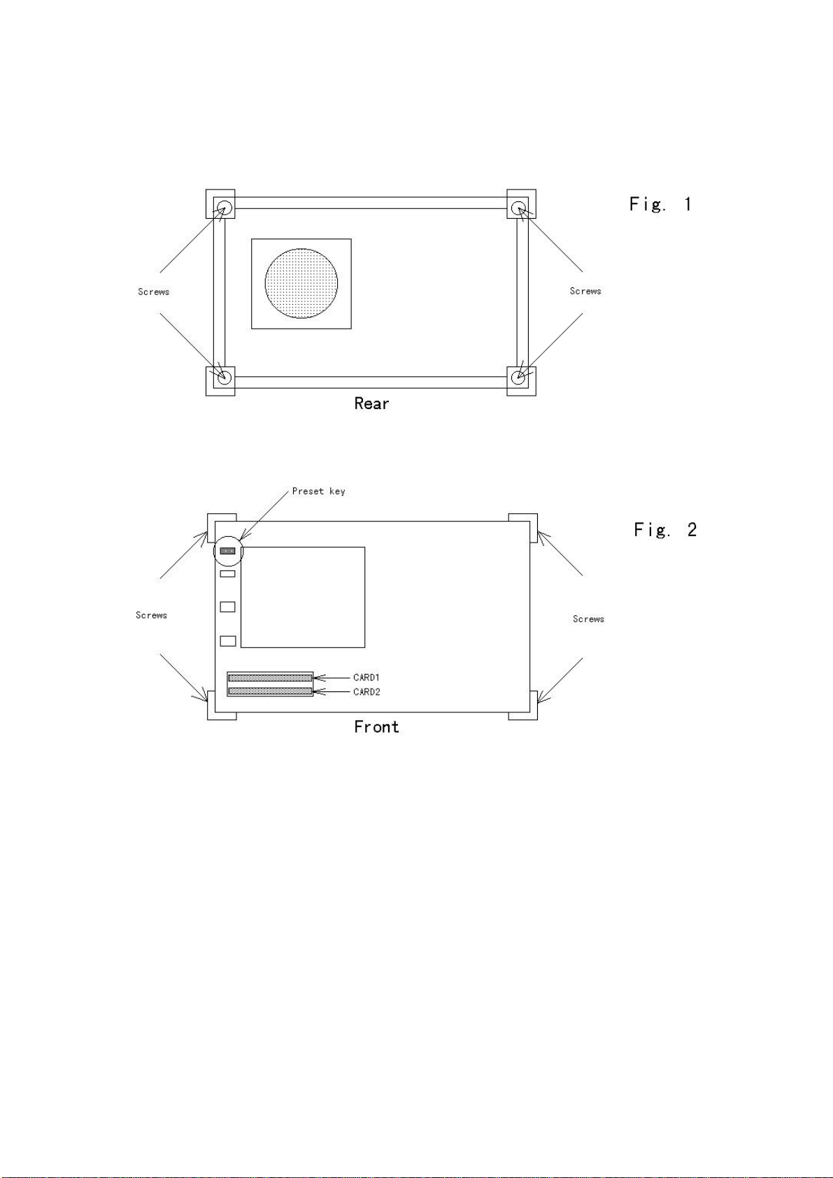
1. Loose and remove four screws on the rear panel. (Fig. 1)
2. Loose four screws on both side of the front. (Fig. 2)
3. Pull the cover toward the rear and remove it.
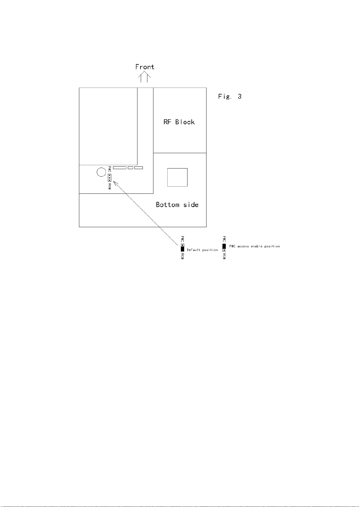
4. Place the short jumper on PMC side. (Fig. 3)
5. Insert the CARD1 into the up side of the memory card slot.
6. Insert the CARD2 into the down side of the memory card slot.
7. Turn the instrument power ON. Then new firmware will be loaded.
The installation will take about 2 minutes.
8. Turn the instrument power OFF when “ Load Complete!!” message is
displayed on the bottom of the screen.
9. Place the short jumper on ROM side. (Fig. 3)
10. Press Preset key and turn the instrument switch ON. Hold the Preset
key until you will see the measurement screen.
11. The firmware update is completed. Place the cover and tight the four
screws on the rear panel. (Fig. 1)
12. Tight the four screws on the side of the front. (Fig. 2)
Page 6
Page 7
Page 8
ADVISORY
CONFIDENTIAL
DISPLAY PROBLEM
MODEL: MS265** and MS266** SERIAL: MS2651B MT26179 or below, MS2653B MT08581 or below MS2661B MT28580 or below, MS2663B MT13975 or below MS2661C MT44079 or below, MS2663C MT21780 or below MS2665C MT14579 or below
Display on the screen of listed instruments might be disturbed when a handy mobile telephone is used in front of the instruments. RF signal from the telephone affects synchronous signal of the driver circuit of the LCD. The LCD driver which includes the synchronous circuit is placed in the front panel assembly. Therefor the circuit picks up the RF signal easily. To solve the problem, the synchronous circuit is separated from the LCD driver and placed in the CPU PCB. This solution requires replacement of two PCBs, A02 FRONT BOARD and A03 CPU. If your customer complains about the problem above, please replace the two PCBs A02 FRONT BOARD and A03 CPU. Anritsu will provide the PCBs with no charge for the complaint. The parts number of the new PCBs are below. All models use same PCBs. Replacement of CPU requires compensation of frequency response.
322U14223 A02 FRONT BOARD 322U14225 A03 CPU
Page 9
ADVISORY
CONFIDENTIAL
POWER SUPPLY COMPATIBILITY
MODEL: MS265** and MS266** SERIAL:
Power supply unit of MS265** and MS266** series has been changed. This redesigned power supply 34Z112975 is meeting EN610000-3-2:1995 Harmonics Current Emission. The new power supply can be replaced instead of old type power supply 34Z106720. On our basic plan, an old type defective power supply should be replaced with an old type power supply. But when 34Z106720 is not stocked, 34Z112975 power supply will be delivered instead of 34Z106720 power supply. That case, the exchange price of 34Z106720 power supply will be applied for the replacement. The other hand 34Z112975 power supply must be replaced with 34Z112975. 34Z106720 power supply should not be installed instead of 34Z112975. Type of power supply and satisfied specification is shown below.
34Z106720 Power Supply EN55011:1991, Group 1, Class A EN50082:1992
34Z112975 Power Supply EN55011:1991, Group 1, Class A EN50082:1992 Harmonic Current Emission EN61000-3-2:1995
Page 10
CONFIDENTIAL 26,Feb.99

POWER SUPPLY COMPATIBILITY (revised)

MODEL: MS265** and MS266** SERIAL:
The information in the service note A-PCC02077 was not correct information about compatibility. The power supply 34Z112975 is not compatible with 34Z106720. So that 34Z106720 should be replaced by 34Z106720 not 34Z112975. Now we have some stock of 34Z106720 for urgent repair.
ADVISORY
Page 11
CONFIDENTIAL 8,Jun.99

SOFTWARE BUG

MODEL: MS2651B, MS2661B and MS2663B SERIAL: See attached list
MS2651B, MS2661B and MS2663B with software issue number 1.50 has problem that can choose only US TV and Japan TV. This problem will be occurred when option 21 or 24 is installed. Listed instruments require software version up when install option 21 or 24 APC will supply memory cards for version up. Each service center should order the
ADVISORY
memory cards when install option 21 or 24 to the listed instruments locally. The version up does not require both calibration and adjustment.
Page 12
List for products shipped with software issue number 13
MODEL ORDER NUMBER SERIAL NUMBER
MS2651B 1-0781-35397 MT44288
1-0732-26513 MT44388
1-0732-26513 MT44488
1-8410-64415 MT44588
1-0729-20122 MT44688
1-0742-19219 MT44788
1-0742-19219 MT44888
1-0783-19625 MT44988
1-3167-61702 MT45088
1-0732-27366 MT45188
1-0732-27528 MT45288
1-0732-27528 MT45388
1-0728-00763 MT45488
1-0728-00755 MT45588
1-0781-36016 MT45688
1-0781-36016 MT45788
1-0715-17332 MT45888
1-8517-06649 MT45988
1-5231-23311 MT46088
1-0781-35834 MT46188
1-0781-35834 MT46288
1-0732-28443 MT46388
1-0732-28443 MT46488
1-0732-28443 MT46588
1-0732-28443 MT46688
1-0732-28443 MT46788
1-0732-28443 MT46888
1-0732-28443 MT46988
1-0732-28443 MT47088
1-0732-28443 MT47188
1-0781-36571 MT47291
1-0729-20262 MT47391
1-0729-20262 MT47491
1-0729-20262 MT47591
1-0781-36555 MT47691
1-5151-42336 MT47791
MS2661B 1-0781-35699 MT33888
1-0781-35699 MT33988
1-0513-39145 MT34288
1-3167-63063 MT34388
MS2663B 1-0732-25894 MT15488
Page 13

ADVISORY

8 November 1999
MISS ASSENBLING OF EXTENDER CABLE
MODEL: 342J109640 EXTENDER CABLE for MS2651A/B/C,/61A/B/C SERIAL: NON
The extender cable menti oned abov e can not be use d for 3GH z conv er ter due to mis s assembling. Therefore 342U107538 PCB of the extender cables that have been delivered already, should be modified as below.
Short pin 1B and pin 2A with a wire.
Page 14

ADVISORY

1 1 August 1999
Exchange module program for old type Spectrum Analyzer
MODEL: MS2651A/MS2661A/MS2653A/MS2663A SERIAL:
The exchange modules in the table attached are some of Module Price List for MS2651B/MS266**. These modules can be used for old type Spectrum analyzer like MS2651A/MS2661A/MS2653A/MS2663A too. So we would like to apply and offer exchange module system for these items only, although you use it for old type Spectrum analyzer. If you want exchange one in the table, please place an order as exchange.
Page 15
MS2651A/61A/53A/63A Exchange Module Price List
Assembly Model Assembly Name Drawing
Number
322U12876 A01 MOTHER BOARD 34Y106673 N/A 11,900 No Yes 322U12853 A04 PMC/GPIB 34Y106693 N/A 18,200 No Yes 34Y112923 A05 SCAN/AD 34Y112923A 33,600 67,200 No Yes 322U12847 A06 IF 34Y110188 39,200 72,800 No Yes 322U12849 A08 LOCAL-A 34Y106679 35,000 65,000 No Yes 322U12930 A09 OPTION BASE 34Y106684 N/A 11,900 No Yes 34Y108179 3GHZ CONVERTER 34Y108179 119,000 204,000 No Yes 34Y108179B 3GHZ CONVERTER 34Y108179B 133,000 228,000 No Yes 34Y110446 A13 MICRO CONVERTER 34Y110446 36,400 67,600 No Yes 34Y110447 A14 1ST LO AMP 34Y110447 N/A 36,400 No Yes 329H13302 8GHz YTF/SW 329H13302 74,200 127,200 No Yes 339H37825 8GHz MIXER 339H37825 N/A 32,200 No Yes 339H40998 HR S-ATT 339H40998 24,500 49,000 No Yes 332U36333 A0501 HI-SPEED AD 34Y106688 N/A * No Yes OPTION 04 322U12979 A0901 TRIG/GATE 34Y106695 N/A * No Y es OPTION 06 322U12981 A0902 AM/FM MONITOR 34Y106699 N/A * No Yes OPTION 07 339H37893 3GHz PRE AMP ASSY 339H37893 29,400 * No Yes OPTION 08 34Y106692B A04 PMC/CENTRONICS 34Y106692B N/A * No Yes OPTION 10 34Y113473 A0904 QP DET 34Y113473 N/A * No Yes OPTION 12.13 322U13502 A04
PMC/GPIB/PARALLEL 322U12983 A0903 TV MONITOR 34Y106697 N/A * No Yes OPTION 15 34Y110293 TG UNIT 34Y110293 87,500 * No Yes OPTION 16
34Y112325 N/A * No Yes OPTION 14
Exchange Price JPY
Full Price
JPY
Export License
Necessity
Compatible with
earlier version
Remarks
* Same as local sales price
Page 16
ADVISORY
7 February 2000
MEMORY CA RD WRI TIING SOFTWARE FOR MS26**
We have distributed memory card writing software for MS2650/60 series. However, the software does not run with the PC depending on the “config.sys”. To use the software correctly, you should change the “config.sys” as follows.
1. Press F8 when booting Windows 95 and choose COMMAND PROMPT ONL Y mode.
2. Save current “config.sys”on a floppy disk.
3. Change the “config.sys” as shown below.
4. Reboot the PC and choose COMMAND PROMPT ONL Y mode ag ain.
5. Now t he so ftw are will r un co rre ctly.
6. After memory card writing is completed, replace the “config.sys” with the one saved at the step 2.
Contents of the “config.sys”. BUFFERS= 20
FILES=30 SHELL=C:¥windows*1¥COMMAND.COM
DEVICEHIGH=C:¥windows¥command*1¥ANSI.SYS
*1: It should be the same directory as the required file is existing.
Page 17
Confidential

ADVISORY

22 November, 2000
Software bug
MODEL : MS26 61C / 63C / 65C Spectrum Analyzer
There are following bugs in a MS2661C / 63C / 65C Spect r um Ana ly zer. When the same fault occurs in a customer, Please inform to us in details.
1.Phenomenon
Rev. no. ROM Ver. (Main)1.52 (Libs)1.50 (Meas)1.54 (ADB)1.51 Updating Date : 12 Aug.1999
◇The C/N measured value disperses in compar ison with the other companies product.
The phenomenon occurs w hen it was measured by the spot mar ker [ dB c/ Hz ] .
Rev. no. ROM Ver. (Main)1.53 (Libs)1.50 (Meas)1.54 (ADB)1.53 Updating Da t e : 6 Oct.1999
◇The “ 0 divide “ error occurs
when the frequency ranging over the Band 0 and Band 1- is s et . Example
Frequency setting : Start 2Ghz Stop 4Ghz
Rev. no. ROM Ver. (Main)1.53 (Libs)1.50 (Meas)1.55 (ADB)1.53 Updating Date : 20 Oct.1999
◇The Channel Power A verage Counter sometimes may not be reset .
Page 18
Rev. no. : ROM Ver. (Main)1.54 (Libs)1.50 (Meas)1.56 (ADB)1.53 Updating Dat e : 6 Nov.1999
◇We pushed the copy key after the marker value comes down dramatically.
Rev. no. : ROM Ver. (Main)1.54 (Libs)1.50 (Meas)1.57 (ADB)1.53 Updating Dat e : 23 Jun.2000
◇The maker signal level rises 2dB over
when the "TSAMP" comman d is executed in the MS2663C 3GHz pre amplifier option.
The "TSAMP" is an exclusive command. The "TSAMP" command is t he R F band section sweeps with the pr e amplifier ON and the micro band section sweeps with the pre ampl if ier OFF in a multi band sweep.
Page 19
Confidential

ADVISORY

8 December, 2000
Vibration of Fan
MODEL : MS2651/61 53/63 65/67 Spectrum Analyzer
The following faults happened in a MS26** series Sp ectrum Analyzer. Please adjust it if the same problem occurs.
1.Phenomenon The vibration of the FAN (34 Z112975 for power supply unit ) is big.
Because the tightening of the screw was too strong (0.5kgfcm) the vibration was transmitted to the package.
put the lock paints
2 . solution Loosening (0.1kgfcm) the tightening of the scr ew and put the lock paint s.
Page 20
CCoonnffiiddeennttiiaal
AADDVVIISSOORRYY
Sep. 26, 2001
Drop of a Tilt handle Screw
The information in this article applies to:
MS2663 seriesSpectrum Analyzer
MS2683A Spectrum Analyzer
MS8608A / 09A Digital Mobile Radio Transmitter Tester
MS8901A Digital Broadcast Signal Analyzer
Symptoms
The screw, which has stopped the tilt handle is dropped and installation becomes unstable.
It is danger when a tilt handle dropped.
l
Cause
The installation screw for the tilt handle loosened. Although fastened with standard torque (12.6kg ~ 17kgf.cm), in order that a handle is a movable
part, so it loosened. Rock Paint had not painted.
Resolution
Lock tightness No.262 are applied to a screw.
Drop of a Tilt handle Screw Lock tightness No.262
Page 21
Power supply unit problem
The information in this article applies to:
z MS2651*/2661* Spectrum Analyzer z MS2663*/2665* Spectrum Analyzer z MS2667*/2668* Spectrum Analyzer
Symptoms
A fuse becomes open and it stops operating.
Cause
A diode may break due to the difference in the transformer characteristic.
CCoonnffiiddeennttiiaal
AADDVVIISSOORRYY
Dec. 04, 2001
l
Resolution
The undermentioned photograph is an improvement power supply unit (With a red mark). On occasions when the power supply unit before improvement breaks down, (no red mark) please return to ATSUGI factory immediately. It exchanges free of charge.
Loading...