


Ametek PK2-20SS, PK2-30SS, PK2-104WC-SS, PK2-254WC-SS, PK2-304WC-SS Operating Manual
...FORM 85-02
June 1999
Revision 6
AMETEK®
PK II Pneumatic
Deadweight Tester
Operating Instructions
 ®
®
CALIBRATION INSTRUMENTS
- 1 -

|
TABLE OF CONTENTS |
|
|
|
Page |
1.0 |
INTRODUCTION AND PRODUCT OVERVIEW ..................................................... |
4 |
1.1 |
PRODUCT FEATURES ........................................................................................... |
4 |
1.2 |
PK II PHYSICAL DIMENSIONS ............................................................................. |
5 |
2.0 |
CORRECTION FACTORS ....................................................................................... |
6 |
2.1 |
Corrections for Gravity ........................................................................................... |
6 |
2.2 |
Corrections for Temperature ................................................................................... |
7 |
2.3 |
Corrections for Air Head ......................................................................................... |
8 |
3.0 |
RECOMMENDED RECERTIFICATION PROCEDURE ........................................... |
8 |
3.1 |
Frequency of Certification ...................................................................................... |
8 |
3.2 |
Materials Necessary for Recertification ................................................................. |
8 |
4.0 |
SPECIFICATIONS ................................................................................................... |
9 |
5.0 |
ASSEMBLY AND SETUP ......................................................................................... |
13 |
5.1 |
Ball and Nozzle ........................................................................................................ |
13 |
5.1.1 Removing the Nozzle .............................................................................................. |
13 |
|
5.1.2 Removing the Ball ................................................................................................... |
13 |
|
5.1.3 Cleaning the Ball and Nozzle ................................................................................... |
13 |
|
5.1.4 Cleanliness Check .................................................................................................. |
13 |
|
5.2 |
Leveling the Tester .................................................................................................. |
13 |
5.2.1 Fast Leveling ........................................................................................................... |
13 |
|
5.2.2 Fine Leveling ........................................................................................................... |
13 |
|
5.3 |
Connection .............................................................................................................. |
14 |
6.0 |
OPERATING INSTRUCTIONS ................................................................................ |
15 |
7.0 |
MAINTENANCE ....................................................................................................... |
16 |
7.1 |
Output System ........................................................................................................ |
16 |
7.2 |
Input System ........................................................................................................... |
17 |
- 2 -

|
TABLE OF CONTENTS |
|
|
|
Page |
8.0 |
TROUBLESHOOTING ............................................................................................ |
18 |
8.1 |
Correcting For Poor Weight Rotation ...................................................................... |
18 |
8.2 |
Output and Internal Leakage ................................................................................... |
18 |
8.2.1 |
Output Connection Leakage ............................................................................. |
18 |
8.2.2 |
Internal Leakage Within the Tester ................................................................... |
18 |
8.3 |
Replacing the Nozzle and O-Ring ............................................................................ |
18 |
9.0 |
PARTS LIST ............................................................................................................. |
19 |
|
TABLES |
|
|
|
Page |
2a |
Pressure in PSIG ..................................................................................................... |
9 |
2b |
Pressure in Inches of Water @ 20°C ..................................................................... |
10 |
2c |
Pressue in Grams per Square Centimeter .............................................................. |
10 |
2d |
Pressure in Kilopascals ........................................................................................... |
11 |
2e |
Pressure in Centimeters of Water @ 20°C ............................................................ |
11 |
2 f |
Pressure in Bar ........................................................................................................ |
12 |
2g |
Pressure in Millimeters of Mercury ......................................................................... |
12 |
PRODUCT WARRANTY
This instrument is warranted against defects in workmanship, material and design for one (1) year from date of delivery to the extent that AMETEK will, at its sole option, repair or replace the instrument or any part thereof which is defective, provided, however, that this warranty shall not apply to instruments subjected to tampering or abuse, or exposed to highly corrosive conditions.
THIS WARRANTY IS IN LIEU OF ALL OTHER WARRANTIES WHETHER EXPRESS OR IMPLIED AND AMETEK HEREBY DISCLAIMS ALL OTHER WARRANTIES, INCLUDING, WITHOUT LIMITATION, ANY WARRANTY OF FITNESS FOR A PARTICULAR PURPOSE OR MERCHANTABILITY. AMETEK SHALL NOT BE LIABLE FOR ANY INCIDENTAL OR CONSEQUENTIAL DAMAGES INCLUDING, BUT NOT LIMITED TO, ANY ANTICIPATED OR LOST PROFITS.
This warranty is voidable if the purchaser fails to follow any and all instructions, warnings, and cautions in the instrument’s Instruction Manual.
If a manufacturing defect is found, AMETEK will replace or repair the instrument or replace any defective part thereof without charge; however, AMETEK’s obligation hereunder does not include the cost of transportation which must be borne by the customer. AMETEK assumes no responsibility for damage in transit, and any claims for such damage should be presented to the carrier by the purchaser.
- 3 -

1.0 INTRODUCTION AND PRODUCT OVERVIEW
The AMETEK® PK II Pneumatic Deadweight Tester is a primary standard that produces a pressure by applying force (weight set) over area (the ceramic ball and nozzle). The PK II tester is NIST traceable and accurate to +0.015% of indicated reading using stainless steel weights calibrated to international standard gravity at 980.665cm/sec2. The unit is intended for low pressure applications up to 30 PSIG (2 bar). The PK II tester may also be calibrated to the user’s local gravity or to inches or centimeters of H2O at 20°C per ISA recommended practices, or to reference water columns at 60°F per AGA standard practices.
The PK II tester is self-regulating with accuracy independent of the operator. The tester utilizes a frictionless ceramic ball which floats on a layer of air within a stainless steel cylinder.
The PK II tester features a sturdy cast-metal base with integral quick-leveling system for field or laboratory use. The case also contains a tripod fixture allowing the unit to be tripod mounted in the field.
1.1 PRODUCT FEATURES
The key features of the PK II Pneumatic Deadweight Tester are:
GAccuracy up to +0.015% of indicated reading
GFloating ball operation eliminates need to rotate weights during testing
GSelf regulating input air flow maintains ball and weights in a float position and compensates for variations in air supply pressure
GRugged ceramic measuring ball withstands harsh environments and field use
GMonocontaminating fluid eliminates the need to clean instruments after calibration or before use
GClose cover operation eliminates wind effects in field calibrations
GMulti-position ball valves for both the inlet and outlet connections ensures trouble-free operation
GCertificate of Accuracy and Traceability available with area, mass and intrinsic correction factors
GRugged aluminum housing offers long life. Top (Front) housing is reversible.
- 4 -

1.2PK II PHYSICAL DIMENSIONS
8.875 in
225.4 mm
12.75in
323.85mm
6.125 in
155.56 mm
3.0 in
76.2 mm
Figure 1.1
PK II Dimensions
(Models 104, 254, 304 and Medical)
- 5 -
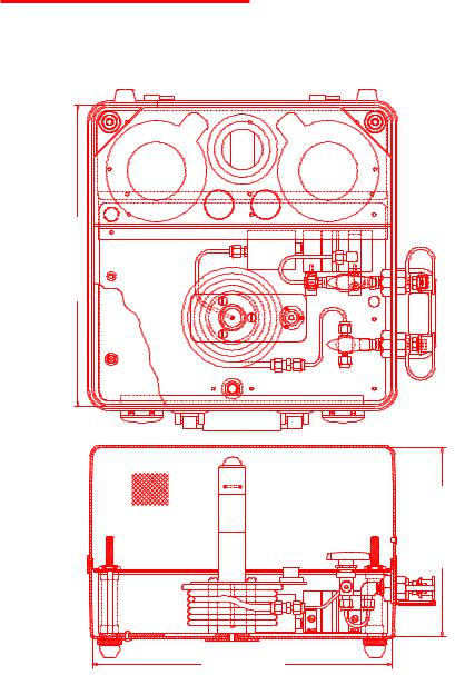
1.2PK II PHYSICAL DIMENSIONS
12.75 in 323.85 mm
8.0 in 203.2 mm
12.875 in
327.03 mm
Figure 1.2
PK II Dimensions
(Models 20SS, 30SS, 654, 854, 2000GM, 2010GM
200N, 201N, 500CM, 1000CM, 1500CM, 2000CM, 2B, 2B01)
- 6 -

2.0CORRECTION FACTORS
An error in pressure determinations may result from any uncertainty of the mass of the loading weights and from the measurement of the effective area of the ball and nozzle. Other sources of error, however, may not be easily recognized. Other sources of error include the air buoyancy of the weights, gravity, thermal expansion and elastic deformation of the ball and nozzle, and the air heads involved. All of these corrections, with the exception of local gravity (except when specified), thermal expansion, and air heads have been corrected for by AMETEK prior to the tester being shipped.
The following technique is suggested to compute the corrected tester output pressure readings:
Gravity
Local gravity values differ depending upon geographic locations. Pressure is defined as “force per unit area”, so that mass values must be converted to force values. To accomplish this, the acceleration of gravity must be used. The acceleration of local gravity may be determined by having a gravitational survey made of the local area with a gravimeter or by contacting various governing bodies such as the National Oceanic and Atmospheric Administration, U.S. Department of Commerce. Once the local value of gravity is known, the pressure may be corrected using the following formula:
G
PG = GW x PN
Where:
P = tester output pressure corrected only for gravity
G
G = local gravity
G = gravity value for which the tester is calibrated
W
P = pressure value of weights applied
N
- 7 -

Temperature
If the coefficient of expansion of the ball and nozzle is positive, the effective area will increase with increasing temperature resulting in a corresponding decrease in pressure. Corrections can be made using the following formula:
|
PT = |
PG |
|
|
|
|
1 + 1.67 x 10 |
-5 |
(T - 23°C) |
||
|
|
|
|||
Where: |
|
|
|
|
|
P |
= tester output pressure corrected only for gravity |
||||
G |
|
|
|
|
|
P |
= tester output pressure corrected for gravity and temperature |
||||
T |
|
|
|
|
|
T |
= ambient temperature (°C) |
|
|
|
|
Air Head
When pressurized, a correction is required only when the gauge height or reference plane of the unit being calibrated is either higher or lower than that of the pneumatic tester. The reference plane of the tester is at the top of the nozzle. Heights above the reference plane are negative, while heights below the reference plane are positive. Corrections can be made using the following formula:
PA = PT (1 + H x 2.84 x 10⁻⁶)
Where:
H = air head (Inches)
P = tester output pressure corrected for gravity and temperature
T
P = tester output pressure corrected for gravity, temperature and air head
A
- 8 -

3.0CALIBRATION AND RECERTIFICATION
The accuracy of measurements can only be ensured through calibration against reference standards of a known and well characterized measurement uncertainty; reference standards that are ultimately traceable through a national standards laboratory to the International Bureau of Weights and Measures (BIPM), to a natural physical constant, or to consensus standards.
All AMETEK pressure calibrations are traceable in the United States of America to reference masters calibrated by the National Institute of Standards and Technology (NIST).
Measurement performance is affected by the frequency and severity of use, the environment, test conditions, and by other factors. AMETEK recommends calibration on a prescribed interval/frequency in order to ensure optimal measurement performance and reliability.
Two types of calibration services are offered:
GCalibration with a Certificate of Conformance/Certificate of Compliance
A statement of conformity which documents that the listed device(s) conforms to published specifications, or the terms of the order/contract. It can provide, in addition, a statement of traceability to NIST.
GCalibration with a Calibration Report/Certificate
A report that outlines detailed information about the calibration process. This includes actual calibration data, traceability information, test conditions, and other factors as may be applicable to the type of device being calibrated.
3.1RECOMMENDED CALIBRATION FREQUENCY
As a general rule, AMETEK pneumatic testers should be tested and recertified every 12 months. Testers used on a more frequent basis should be tested more frequently.
3.2MATERIALS NECESSARY FOR RECERTIFICATION
Both the tester assembly and weight set should be returned to AMETEK in order to allow for calibration of the tester as a “system”. Pressure is a derived parameter requiring determinations of both effective area and force (weight-mass). Instruments not sent to AMETEK as a “system” can only be provided with certifications on the parameter calibrated, e.g. effective area or mass.
All materials should be securely packaged to prevent damage during transportation and handling. Testers should be returned in their case. The ball/nozzle assembly should be wrapped with adequate padding material and well secured to avoid shifting, movement and to protect them from shock during transportation.
- 9 -
 Loading...