


PROGRAMMABLE POWER
XG Family Programmable DC
Power Supply
Operating Manual (firmware v 2.0 and higher)
670 Watts – 1700 Watts
Half Rack |
|
Full Rack |
|
|
6 V to 600 V Models: |
||
6-110 |
|
6-220 |
6-220 |
8-100 |
|
8-187.5 |
8-200 |
12-70 |
|
12.5-120 |
12-140 |
20-42 |
|
20-76 |
20-84 |
33-25 |
|
30-50 |
33-50 |
40-21 |
|
40-38 |
40-42 |
60-14 |
|
60-25 |
60-28 |
80-10.5 |
|
80-19 |
80-21 |
100-8.5 |
|
100-15 |
100-17 |
150-5.6 |
|
150-10 |
150-11.2 |
300-2.8 |
|
300-5 |
300-5.6 |
600-1.4 |
|
600-2.6 |
600-2.8 |
M370430-01 Rev E |
www.programmablepower.com |

About AMETEK
AMETEK Programmable Power, Inc., a Division of AMETEK, Inc., is a global leader in the design and manufacture of precision, programmable power supplies for R&D, test and measurement, process control, power bus simulation and power conditioning applications across diverse industrial segments. From bench top supplies to rack-mounted industrial power subsystems, AMETEK Programmable Power is the proud manufacturer of Elgar, Sorensen, California Instruments and Power Ten brand power supplies.
AMETEK, Inc. is a leading global manufacturer of electronic instruments and electromechanical devices with annualized sales of $2.5 billion. The Company has over 11,000 colleagues working at more than 80 manufacturing facilities and more than 80 sales and service centers in the United States and around the world.
Trademarks
AMETEK is a registered trademark of AMETEK, Inc. Sorensen is a trademark owned by AMETEK, Inc. Other trademarks, registered trademarks, and product names are the property of their respective owners and are used herein for identification purposes only.
Notice of Copyright
XG Family Programmable DC Power Supply Operating Manual (firmware v 2.0 and higher) © 2008-2014 AMETEK Programmable Power, Inc. All rights reserved.
Exclusion for Documentation
UNLESS SPECIFICALLY AGREED TO IN WRITING, AMETEK PROGRAMMABLE POWER, INC. (“AMETEK”):
(a)MAKES NO WARRANTY AS TO THE ACCURACY, SUFFICIENCY OR SUITABILITY OF ANY TECHNICAL OR OTHER INFORMATION PROVIDED IN ITS MANUALS OR OTHER DOCUMENTATION.
(b)ASSUMES NO RESPONSIBILITY OR LIABILITY FOR LOSSES, DAMAGES, COSTS OR EXPENSES, WHETHER SPECIAL, DIRECT, INDIRECT, CONSEQUENTIAL OR INCIDENTAL, WHICH MIGHT ARISE OUT OF THE USE OF SUCH INFORMATION.
THE USE OF ANY SUCH INFORMATION WILL BE ENTIRELY AT THE USER'S RISK, AND
(c)REMINDS YOU THAT IF THIS MANUAL IS IN ANY LANGUAGE OTHER THAN ENGLISH, ALTHOUGH STEPS HAVE BEEN TAKEN TO MAINTAIN THE ACCURACY OF THE TRANSLATION, THE ACCURACY CANNOT BE GUARANTEED. APPROVED AMETEK CONTENT IS CONTAINED WITH THE ENGLISH LANGUAGE VERSION, WHICH IS POSTED AT WWW.PROGRAMMABLEPOWER.COM.
Date and Revision
June 2014 Revision E
Part Number
M370430-01
Contact Information
Telephone: 800 733 5427 (toll free in North America) 858 450 0085 (direct)
Fax: 858 458 0267
Email: sales@programmablepower.com service@programmablepower.com
Web: www.programmablepower.com
M370430-01 Rev E |
i |

Product Family: XG Family Programmable DC Power Supply
Warranty Period: Five Years
WARRANTY TERMS
AMETEK Programmable Power, Inc. (“AMETEK”), provides this written warranty covering the Product stated above, and if the Buyer discovers and notifies AMETEK in writing of any defect in material or workmanship within the applicable warranty period stated above, then AMETEK may, at its option: repair or replace the Product; or issue a credit note for the defective Product; or provide the Buyer with replacement parts for the Product.
The Buyer will, at its expense, return the defective Product or parts thereof to AMETEK in accordance with the return procedure specified below. AMETEK will, at its expense, deliver the repaired or replaced Product or parts to the Buyer. Any warranty of AMETEK will not apply if the Buyer is in default under the Purchase Order Agreement or where the Product or any part thereof:
∙is damaged by misuse, accident, negligence or failure to maintain the same as specified or required by AMETEK;
∙is damaged by modifications, alterations or attachments thereto which are not authorized by AMETEK;
∙is installed or operated contrary to the instructions of AMETEK;
∙is opened, modified or disassembled in any way without AMETEK's consent; or
∙is used in combination with items, articles or materials not authorized by AMETEK.
The Buyer may not assert any claim that the Products are not in conformity with any warranty until the Buyer has made all payments to AMETEK provided for in the Purchase Order Agreement.
PRODUCT RETURN PROCEDURE
1.Request a Return Material Authorization (RMA) number from the repair facility (must be done in the country in which it was purchased):
∙In the USA, contact the AMETEK Repair Department prior to the return of the product to AMETEK for repair:
Telephone: 800-733-5427, ext. 2295 or ext. 2463 (toll free North America) 858-450-0085, ext. 2295 or ext. 2463 (direct)
∙Outside the United States, contact the nearest Authorized Service Center (ASC). A full listing can be found either through your local distributor or our website, www.programmablepower.com, by clicking Support and going to the Service Centers tab.
2.When requesting an RMA, have the following information ready:
∙Model number.
∙Serial number
∙Description of the problem
NOTE: Unauthorized returns will not be accepted and will be returned at the shipper's expense.
NOTE: A returned product found upon inspection by AMETEK, to be in specification is subject to an evaluation fee and applicable freight charges.
ii |
M370430-01 Rev E |
About This Manual (firmware v2.0 and higher)
Purpose
The Operating Manual provides installation and operating information for the XG Family Programmable DC Power Supply.
Scope
The Manual provides safety information, features and specifications, installation procedures, functional test procedures, and operating procedures for both local (front panel) operation and remote operation.
The Manual also provides information on the GPIB interface option an LXI compliant Ethernet (ENET) interface for models with the MEB options.
Audience
The Manual is intended for the user who is familiar with electronic power supplies, Constant Voltage, Constant Current, and/or Constant Power operating modes, and the control of output power. The user should be familiar with practicing safe techniques while making supply or pin connections.
Conventions Used
The following conventions are used in this guide.
WARNING
Warnings identify conditions or practices that could result in personal injury or loss of life.
CAUTION
Cautions identify conditions or practices that could result in damage to the unit or other equipment.
Important: Important notes provide information that is important for you to know. They are not as serious as Warnings or Cautions.
M370430-01 Rev E |
iii |

About This Manual
Related Information
More information about AMETEK Programmable as well as its products and services, is available at www.programmablepower.com.
Acronyms
Acronym |
Definition |
|
|
APG |
Analog Programming |
|
|
AUX |
Auxiliary |
|
|
ENET |
Ethernet |
|
|
FGA |
Finished Goods Assembly |
|
|
ISOL |
Isolated Analog Programming |
|
|
OCP |
Over Current Protection |
|
|
OTP |
Over Temperature Protection |
|
|
OVP |
Over Voltage Protection |
|
|
PSU |
Power Supply Unit |
|
|
TVS |
Transient Voltage Suppressor |
|
|
UVP |
Under Voltage Protection |
|
|
Font Conventions
This Manual uses the following typographical conventions:
7 Segment |
For display and readback information on the |
|
output voltage and current displays. |
|
|
Command body text |
Represents SCPI commands. |
|
|
iv |
M370430-01 Rev E |
Important Safety Instructions
WARNING: High energy and high voltage
Exercise caution when using a power supply. High energy levels can be stored at the output voltage terminals on a power supply in normal operation. In addition, potentially lethal voltages exist in the power circuit and on the output and sense connectors of a power supply with a rated output greater than 40 V. Filter capacitors store potentially dangerous energy for some time after power is removed.
WARNING: Fire hazard
Operate the power supply in an environment free of flammable gases or fumes. To ensure that the power supply's safety features are not compromised, use the power supply as specified in this Manual and do not substitute parts or make any unauthorized modifications. If service is necessary, please return the power supply to the Authorized Service Center. See the Warranty on page ii.
WARNING: Limitations on use
The XG Family Programmable DC Power Supply is not intended for use in connection with life support systems or other medical equipment or devices.
CAUTION: For use as a battery charger
When you are using a power supply for battery charging applications, it is essential to provide an appropriately sized fuse or circuit breaker in series between the power supply output and the battery.
Installation of a protector (fuse or DC circuit breaker), rated for about 115% of the maximum current rating of the power supply and designed specifically to interrupt the DC voltage of the battery, will provide adequate current protection. Where several power supplies are in parallel, it is best to fuse each power supply rather than use one fuse at the battery.
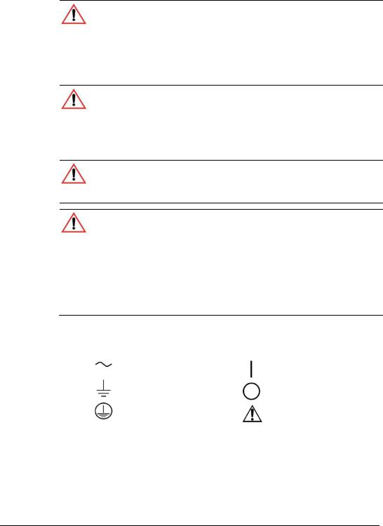
Power Supply Safety Markings
Alternating Current |
On (Supply) |
Earth (Ground) Terminal |
Off (Supply) |
Protective Conductor Terminal |
Caution (Check the Manualfor |
|
additional information.) |
M370430-01 Rev E |
v |

Safety
Standard Warnings
WARNING: Keep these instructions
This chapter contains important safety and operating instructions. Read and keep this Operating Manual for future reference.
1.Before installing and using the XG Family Programmable DC Power Supply, read all instructions and cautionary markings on the instrument and all appropriate sections of this Manual.
2.This instrument is for indoor use only. Do not expose the instrument to moisture. To reduce risk of fire hazard, do not cover or obstruct the ventilation openings. Be sure to install the instrument in a compartment which allows air to reach the ventilation inlets on the front and rear of the unit to prevent overheating. For more information, see “ Ventilation” on page 2-4.
3.To avoid a risk of fire and electric shock, make sure that the existing wiring is in good condition and the wire is not undersized. Do not operate the instrument with damaged or substandard wiring.
4.Do not operate the instrument if it has received a sharp blow, been dropped, or otherwise damaged in any way. If the instrument is damaged, see the Warranty on page ii.
5.Do not disassemble the instrument. It contains no user-serviceable parts. See the Warranty on page ii for instructions on obtaining service. Attempting to service the instrument yourself may result in a risk of electrical shock or fire. Internal capacitors remain charged after all power is disconnected.
6.To reduce the risk of electrical shock, disconnect AC power from the instrument before attempting any maintenance or cleaning or working on any circuits connected to the instrument. Turning off controls will not reduce this risk.
vi |
M370430-01 Rev E |

Contents
1 INTRODUCTION............................................................................................. |
1-1 |
FEATURES AND OPTIONS................................................................................... |
1-2 |
XG MODELS (FIRMWARE VERSION 2.0 AND HIGHER) ............................................ |
1-3 |
FRONT PANEL................................................................................................... |
1-5 |
Front Panel Display and Controls ....................................................................... |
1-6 |
REAR PANEL CONNECTORS ON 850 WATT MODELS ............................................ |
1-7 |
REAR PANEL CONNECTORS ON 1500 AND 1700 WATT MODELS............................ |
1-9 |
2 INSTALLATION .............................................................................................. |
2-1 |
BASIC SETUP PROCEDURE ................................................................................ |
2-2 |
STEP 1: INSPECTING AND CLEANING................................................................... |
2-3 |
Initial Inspection ................................................................................................. |
2-3 |
Periodic Cleaning ............................................................................................... |
2-3 |
STEP 2: LOCATION AND MOUNTING .................................................................... |
2-4 |
Rack Mounting ................................................................................................... |
2-4 |
Purchasing Rack Mount Kits............................................................................... |
2-4 |
Ventilation .......................................................................................................... |
2-4 |
STEP 3: CONNECTING AC INPUT POWER ............................................................ |
2-5 |
XG 850 Watt AC Input Connector ....................................................................... |
2-5 |
XG 1500 and 1700 Watt AC Input Connector...................................................... |
2-6 |
XG 1500 and 1700 Watt AC Input Wire .............................................................. |
2-6 |
XG 1500 and 1700 Watt AC Input Wire Connection ............................................ |
2-7 |
STEP 4: SELECTING LOAD WIRES....................................................................... |
2-8 |
Load Wiring........................................................................................................ |
2-8 |
Insulation Rating ................................................................................................ |
2-8 |
Current Carrying Capacity .................................................................................. |
2-8 |
Maximum Load Wiring Length For Operation With Sense Lines.......................... |
2-9 |
Noise and Impedance Effects............................................................................. |
2-9 |
STEP 5: PERFORMING FUNCTIONAL TESTS ....................................................... |
2-10 |
Powering the Power Supply On/Off .................................................................. |
2-10 |
Voltage and Current Mode Operation Checks................................................... |
2-11 |
STEP 6: CONNECTING LOADS .......................................................................... |
2-12 |
DC Output Connectors ..................................................................................... |
2-12 |
Inductive Loads and Batteries........................................................................... |
2-13 |
Connecting Single Loads.................................................................................. |
2-14 |
Connecting Multiple Loads ............................................................................... |
2-14 |
STEP 7: CONNECTING REMOTE SENSING.......................................................... |
2-15 |
M370430-01 Rev E |
vii |

Contents
3 LOCAL OPERATION...................................................................................... |
3-1 |
INTRODUCTION ................................................................................................. |
3-2 |
CONFIGURING SETTINGS FROM THE FRONT PANEL ............................................. |
3-2 |
Using the 9-Position Mode Control ..................................................................... |
3-2 |
Using the Rotary Adjust/Enter Control ................................................................ |
3-2 |
Coarse and Fine Adjustment Modes................................................................... |
3-3 |
NAVIGATING THE MENU SYSTEM ........................................................................ |
3-4 |
Setting VOLTS and AMPS Modes ...................................................................... |
3-4 |
Normal Display Mode and Inactivity Timeout ...................................................... |
3-6 |
DISPLAY MESSAGES ON THE FRONT PANEL ........................................................ |
3-8 |
STANDARD (LOCAL) OPERATION ...................................................................... |
3-10 |
Operating Modes.............................................................................................. |
3-10 |
Shipped Configuration (Local Operation) .......................................................... |
3-16 |
ENABLING THE OUTPUT ................................................................................... |
3-16 |
ENABLING THE AUXILIARY OUTPUT................................................................... |
3-17 |
OUTPUT AUTO START MODE (AUTO RESTART) ................................................. |
3-17 |
AUXILIARY AUTO START MODE ........................................................................ |
3-18 |
CONSTANT POWER MODE (VERSION 2.21 AND HIGHER)..................................... |
3-18 |
ALARMS AND ERRORS ..................................................................................... |
3-20 |
Clearing Alarms................................................................................................ |
3-21 |
Front Panel ALARM LED.................................................................................. |
3-22 |
Alarm Masking ................................................................................................. |
3-23 |
Alarm Output Latching...................................................................................... |
3-24 |
SETTING FOLDBACK MODE .............................................................................. |
3-25 |
Resetting Activated Foldback Protection........................................................... |
3-26 |
USING OVER VOLTAGE PROTECTION (OVP) ..................................................... |
3-27 |
Defining the OVP Set Point .............................................................................. |
3-28 |
USING UNDER VOLTAGE PROTECTION (UVP) ................................................... |
3-29 |
Defining the UVP Set Point............................................................................... |
3-29 |
OVER CURRENT PROTECTION (OCP)............................................................... |
3-30 |
USING OVER TEMPERATURE PROTECTION LOCK (OTP) .................................... |
3-31 |
Defining the OTP Mode .................................................................................... |
3-31 |
Resetting in Latch Mode................................................................................... |
3-31 |
USING THE EXTERNAL SHUTDOWN FUNCTION................................................... |
3-32 |
Activating the External Shutdown Function ....................................................... |
3-32 |
Controlling the External Shutdown Function ..................................................... |
3-32 |
Defining the Polarity of the External Shutdown Signal....................................... |
3-33 |
LOOP PROTECTION (VERSION 2.21 AND HIGHER)............................................... |
3-33 |
Setting up Loop Protection ............................................................................... |
3-34 |
INTERLOCK FUNCTION ..................................................................................... |
3-35 |
viii |
M370430-01 Rev E |
|
Contents |
Defining the Interlock Mode .............................................................................. |
3-35 |
OUTPUT PROTECTION ..................................................................................... |
3-35 |
Programming Voltage Output Preset ................................................................ |
3-35 |
Programming Current Output Preset ................................................................ |
3-36 |
Power On Status Signal ................................................................................... |
3-37 |
HARDWARE MALFUNCTION ALARMS ................................................................. |
3-37 |
CURRENT CONFIGURATION MEMORY SETTINGS................................................ |
3-38 |
USER SETTING MEMORY LOCATIONS ............................................................... |
3-39 |
Saving User Setting Memory Locations ............................................................ |
3-40 |
Recalling User Setting Memory Locations......................................................... |
3-40 |
LOCAL LOCKOUT ............................................................................................. |
3-41 |
Enabling Local Lockout .................................................................................... |
3-41 |
Disabling Local Lockout.................................................................................... |
3-41 |
RESETTING THE POWER SUPPLY...................................................................... |
3-42 |
USING MULTIPLE POWER SUPPLIES ................................................................. |
3-44 |
Configuring Multiple Supplies for Series Operation ........................................... |
3-46 |
Configuring Multiple Supplies for Current Sharing Operation (APG Method) ..... |
3-49 |
Connecting to the Load in Local Sensing Mode (Parallel Control Method)......... |
3-51 |
Connecting to the Load in Remote Sensing Mode (Parallel Control Method)..... |
3-52 |
4 ANALOG PROGRAMMING (APG) AND ISOLATED ANALOG |
|
PROGRAMMING (ISOL)................................................................................. |
4-1 |
INTRODUCTION ................................................................................................. |
4-2 |
Analog Programming (APG) of Output Voltage and Output Current .................... |
4-2 |
Remote Programming Options ........................................................................... |
4-3 |
Analog Programming (APG) Connector J1 ......................................................... |
4-5 |
ANALOG PROGRAMMING MODE.......................................................................... |
4-9 |
Analog Programming With External Voltage Source ........................................... |
4-9 |
Voltage-Controlled Voltage APG Setup ............................................................ |
4-10 |
Voltage-Controlled Current APG Setup............................................................. |
4-12 |
Resistive-Controlled Voltage APG Setup .......................................................... |
4-15 |
Resistive-Controlled Current APG Setup .......................................................... |
4-17 |
Voltage and Current Readback......................................................................... |
4-19 |
ISOLATED ANALOG PROGRAMMING MODE (ISOL) ............................................. |
4-20 |
AUX Output and Isolated Analog Programming (ISOL) Connector .................... |
4-20 |
Voltage-Controlled Voltage ISOL Setup............................................................ |
4-23 |
Voltage-Controlled Current ISOL Setup ............................................................ |
4-25 |
Resistive-Controlled Voltage ISOL Setup.......................................................... |
4-28 |
Resistive-Controlled Current ISOL Setup.......................................................... |
4-30 |
VOLTAGE AND CURRENT READBACK (ISOLATED)............................................... |
4-32 |
M370430-01 Rev E |
ix |

Contents
5 REMOTE OPERATION................................................................................... |
5-1 |
INTRODUCTION ................................................................................................. |
5-2 |
HARDWARE AND CONNECTION SETUP ................................................................ |
5-2 |
Configuring Remote Control Using RS-232......................................................... |
5-2 |
Configuring Remote Control Using RS-485......................................................... |
5-7 |
Configuring Remote Control using the USB Connector ....................................... |
5-9 |
Setting Up the PC to Use the USB Connection ................................................... |
5-9 |
GPIB Connector (Optional)............................................................................... |
5-15 |
Ethernet/LAN (ENET) Connector (Optional)...................................................... |
5-19 |
Multiple Power Supply Connections to RS-485 Bus .......................................... |
5-19 |
TERMINAL CONFIGURATION ............................................................................. |
5-21 |
Data Format ..................................................................................................... |
5-21 |
End of Message ............................................................................................... |
5-21 |
HyperTerminal.................................................................................................. |
5-21 |
Selecting the Appropriate Communication Port ................................................. |
5-24 |
Multichannel Address Setting ........................................................................... |
5-25 |
Remote Interface Addressing ........................................................................... |
5-26 |
Multichannel Commands Explained.................................................................. |
5-27 |
Status Reporting in SCPI.................................................................................. |
5-29 |
STATUS REGISTERS MODEL FROM IEEE 488.2................................................. |
5-31 |
STATUS BYTE ................................................................................................. |
5-32 |
Error/Event Queue (ERR)................................................................................. |
5-32 |
Questionable Status Register Summary (QSR) ................................................ |
5-32 |
Message Available (MAV) ................................................................................ |
5-33 |
Standard Event Status Summary (ESB) ........................................................... |
5-33 |
Master Summary Status (MSS) ........................................................................ |
5-33 |
Request Service (RQS) .................................................................................... |
5-33 |
Operation Status Register Summary (OSR)...................................................... |
5-34 |
Standard Event Status Register (SESR) ........................................................... |
5-35 |
STANDARD SCPI REGISTER STRUCTURE ......................................................... |
5-38 |
OPERATION STATUS REGISTER ...................................................................... |
5-39 |
CURRENT SHARE SUB-REGISTER .................................................................... |
5-42 |
Operation Status Register Commands.............................................................. |
5-43 |
Current Sharing Sub-Register Commands........................................................ |
5-44 |
Shutdown Sub-Register Commands ................................................................. |
5-45 |
Protection Sub-Register Commands................................................................. |
5-46 |
QUESTIONABLE STATUS REGISTER ................................................................. |
5-47 |
VOLTage Sub-Register .................................................................................... |
5-50 |
TEMPerature Sub-Register .............................................................................. |
5-50 |
Questionable Status Register Commands ........................................................ |
5-51 |
x |
M370430-01 Rev E |

|
Contents |
Voltage Status Register Commands ................................................................. |
5-52 |
Temperature Status Register Commands ......................................................... |
5-53 |
SCPI ERROR/EVENT QUEUE ........................................................................... |
5-54 |
Reset Command .............................................................................................. |
5-56 |
Clear All Status Registers................................................................................. |
5-57 |
SCPI Preset Status .......................................................................................... |
5-58 |
Command Line Help System ............................................................................ |
5-59 |
LOCKING AND UNLOCKING THE FRONT PANEL................................................... |
5-62 |
Auto Sequence Programming........................................................................... |
5-62 |
CONFIGURE OTHER PROTECTION MECHANISMS................................................ |
5-68 |
Foldback Protection.......................................................................................... |
5-68 |
Over Temperature Protection ........................................................................... |
5-69 |
Loop Protection Enable/Disable........................................................................ |
5-69 |
Interlock Enable/Disable................................................................................... |
5-70 |
Save and Recall ............................................................................................... |
5-71 |
Set Analog Programming Level ........................................................................ |
5-71 |
Set Remote Programming Interface.................................................................. |
5-72 |
Protection Mask (Enable Alarms)...................................................................... |
5-73 |
Power Saving Control (Sleep Mode, XG 1700 W Only) ..................................... |
5-74 |
6 COMMUNICATIONS OPTIONS ...................................................................... |
6-1 |
INTRODUCTION............................................................................................. |
6-2 |
SETTING UP LAN/ETHERNET ....................................................................... |
6-3 |
Basics ................................................................................................................ |
6-3 |
LOCAL AREA NETWORK (LAN) OPTION....................................................... |
6-5 |
Media Access Control (MAC) Address................................................................ |
6-5 |
Communication Configuration............................................................................. |
6-6 |
LAN Connection ................................................................................................. |
6-6 |
Direct-to-PC Connection..................................................................................... |
6-6 |
Private Network Connection ............................................................................... |
6-7 |
CONNECTING TO A NETWORK .................................................................... |
6-8 |
Connecting with PC on Same Side of Router as Power Supply........................... |
6-8 |
Connecting with Power Supply Hidden Behind a Router ................................... |
6-10 |
Socket Port Number ......................................................................................... |
6-12 |
Instrument Drivers and Application Software..................................................... |
6-13 |
AMETEK LXI DISCOVERY BROWSER......................................................... |
6-13 |
Installing the AMETEK LXI Discovery Browser ................................................. |
6-13 |
Using the AMETEK LXI Discovery Browser ...................................................... |
6-21 |
AMETEK ENETTEST UTILITY......................................................................... |
6-22 |
Installing the AMETEK EnetTest Utility ............................................................. |
6-22 |
Using the AMETEK Ethernet Test Utility ........................................................... |
6-28 |
M370430-01 Rev E |
xi |

Contents
SETTING LAN PARAMETERS...................................................................... |
6-29 |
Setting LAN Parameters via Ethernet ............................................................... |
6-29 |
Setting LAN Parameters via Serial or USB Port ................................................ |
6-29 |
Setting LAN Parameters via Web Interface....................................................... |
6-30 |
SETTING A STATIC IP ADDRESS THROUGH ETHERNET, USB, SERIAL INTERFACES |
|
...................................................................................................................... |
6-35 |
Ethernet ........................................................................................................... |
6-35 |
USB ................................................................................................................. |
6-36 |
RS232 (SERIAL) .............................................................................................. |
6-44 |
SYSTEM COMMANDS.................................................................................. |
6-53 |
Subsystem Syntax............................................................................................ |
6-53 |
LXI COMPLIANCE ........................................................................................ |
6-56 |
Introduction to the LXI Standard ....................................................................... |
6-57 |
VXI Discovery .................................................................................................. |
6-57 |
LAN Requirements ........................................................................................... |
6-57 |
Web Page ........................................................................................................ |
6-57 |
Remote Procedure Calls (RPC)........................................................................ |
6-58 |
Drivers ............................................................................................................. |
6-58 |
7 CALIBRATION AND TROUBLESHOOTING .................................................. |
7-1 |
INTRODUCTION ................................................................................................. |
7-2 |
MAIN VOLTAGE AND CURRENT CALIBRATION PRINCIPLE ...................................... |
7-3 |
Understanding the Problem ................................................................................ |
7-3 |
Step 1: Gain Calibration ..................................................................................... |
7-4 |
Step 2: Offset Calibration ................................................................................... |
7-4 |
Step 3: Recalibrate Gain .................................................................................... |
7-5 |
STORING CALIBRATION DATA............................................................................. |
7-5 |
CALIBRATING THE OUTPUT VOLTAGE.................................................................. |
7-6 |
Gain Calibration ................................................................................................. |
7-6 |
Offset Calibration ............................................................................................... |
7-6 |
CALIBRATING THE OUTPUT CURRENT ................................................................. |
7-7 |
Gain Calibration ................................................................................................. |
7-7 |
Offset Calibration ............................................................................................... |
7-8 |
OVER VOLTAGE PROTECTION CALIBRATION........................................................ |
7-9 |
NON-ISOLATED ANALOG PROGRAMMING CALIBRATION ...................................... |
7-10 |
Non-isolated Voltage Monitoring Calibration ..................................................... |
7-10 |
Non-isolated Current Monitoring Calibration ..................................................... |
7-11 |
Non-isolated Voltage Programming of Voltage Calibration ................................ |
7-12 |
Non-isolated Resistive Programming of Voltage Calibration.............................. |
7-13 |
Non-isolated Voltage Programming of Current Calibration ................................ |
7-14 |
Non-isolated Resistive Programming of Current Calibration .............................. |
7-15 |
xii |
M370430-01 Rev E |

|
Contents |
CALIBRATION PROCEDURE FOR ISOLATED MODES ............................................ |
7-16 |
Isolated Voltage Monitoring Calibration............................................................. |
7-16 |
Isolated Current Monitoring Calibration............................................................. |
7-17 |
Isolated Voltage Programming of Voltage Calibration ....................................... |
7-18 |
Isolated Resistive Programming of Voltage Calibration ..................................... |
7-19 |
Isolated Voltage Programming of Current Calibration........................................ |
7-20 |
Isolated Resistive Programming of Current Calibration ..................................... |
7-21 |
Calibrating the Input Voltage APG Signal.......................................................... |
7-22 |
Calibrating the Input Current APG Signal.......................................................... |
7-23 |
RESTORE FACTORY CALIBRATION .................................................................... |
7-25 |
RESTORE DEFAULT CALIBRATION .................................................................... |
7-25 |
USER DIAGNOSTICS ........................................................................................ |
7-25 |
Emergency Shutdown ...................................................................................... |
7-26 |
Unusual or Erratic Operation ............................................................................ |
7-26 |
Troubleshooting for Operators .......................................................................... |
7-27 |
APPENDIX A SCPI COMMAND REFERENCE.................................................... |
A-1 |
SCPI CONFORMANCE INFORMATION ................................................................. |
A-2 |
Codes and Standards......................................................................................... |
A-2 |
IEEE 488.2/SCPI Syntax and Style..................................................................... |
A-2 |
SCPI Command Hierarchy ................................................................................. |
A-3 |
Using SCPI Commands...................................................................................... |
A-4 |
Parameter Types................................................................................................ |
A-7 |
SCPI COMMAND TREE ..................................................................................... |
A-8 |
SCPI Command Summary ............................................................................... |
A-14 |
APPENDIX B ERROR MESSAGES ................................................................... |
B-1 |
ERROR MESSAGES .......................................................................................... |
B-2 |
Command Error List ........................................................................................... |
B-3 |
Execution Error List ............................................................................................ |
B-4 |
Device-Specific Error List ................................................................................... |
B-5 |
Query Error List.................................................................................................. |
B-6 |
APPENDIX C SPECIFICATIONS....................................................................... |
C-1 |
ELECTRICAL SPECIFICATIONS FOR XG FAMILY, 850 W ....................................... |
C-2 |
AC Line Input Specifications for XG 850 Watt ..................................................... |
C-3 |
ELECTRICAL SPECIFICATIONS FOR XG FAMILY, 1500 W ..................................... |
C-4 |
AC Line Input Specifications for XG 1500 Watt ................................................... |
C-5 |
ELECTRICAL SPECIFICATIONS FOR XG FAMILY, 1700 W ..................................... |
C-6 |
AC Line Input Specifications for XG 1700 Watt ................................................... |
C-7 |
REMOTE OPERATION PROGRAMMING ................................................................ |
C-8 |
COMMON SPECIFICATIONS FOR ALL MODELS..................................................... |
C-9 |
APPENDIX D RACK MOUNT OPTIONS AND INSTALLATION INSTRUCTIONS.......... |
D-1 |
M370430-01 Rev E |
xiii |

Contents
RACK MOUNT KIT OPTIONS .............................................................................. |
D-2 |
|
XG Single (Half Rack) and Dual (Full Rack)........................................................ |
D-2 |
|
Location Requirements....................................................................................... |
D-3 |
|
MOUNTING OPTION A: 1U RAILS ....................................................................... |
D-4 |
|
Tools and Materials Required ............................................................................. |
D-4 |
|
Installation Procedures ....................................................................................... |
D-4 |
|
MOUNTING OPTION B: MANUFACTURED SLIDES FROM JONATHAN®ENGINEERED |
|
|
SOLUTIONS...................................................................................................... |
D-6 |
|
APPENDIX E LANTRONIX PROCEDURES FOR MEA OPTION ............................. |
E-1 |
|
INTRODUCTION ................................................................................................ |
E-2 |
|
Setting Up the Computer .................................................................................... |
E-2 |
|
Software Installations ......................................................................................... |
E-4 |
|
Configuring the Device Using DeviceInstaller...................................................... |
E-6 |
|
Terminal Configuration ..................................................................................... |
E-12 |
|
Advanced Section ............................................................................................ |
E-17 |
|
Network Topology 1: Simple LAN ..................................................................... |
E-17 |
|
Network Topology 2: ENET and RS-485 Bus.................................................... |
E-20 |
|
Troubleshooting for XG 850W Model with ENET and/or RS-485 Communication |
||
........................................................................................................................ |
|
E-23 |
INDEX.................................................................................................................. |
|
1 |
Figures |
|
|
Figure 1-1 XG Front Panels (Half Rack, above; Full Rack, below; not to-scale) ............ |
1-5 |
|
Figure 1-2 Front Panel Display and Controls ................................................................ |
1-6 |
|
Figure 1-3 XG 850 Watt Units: 6 V to 40 V Models....................................................... |
1-7 |
|
Figure 1-4 |
XG 850 Watt Units: 60 V to 150 V Models .................................................. |
1-7 |
Figure 1-5 XG 850 Watt Units: 300 V to 600 V Models ................................................. |
1-7 |
|
Figure 1-6 XG 1500 and 1700 Watt Units: 6 V to 40 V Models ..................................... |
1-9 |
|
Figure 1-7 XG 1500 and 1700 Watt Units: 60 V to 600 V Models................................ |
1-10 |
|
Figure 2-1 1500 and 1700 Watt AC Input Cover and Strain Relief ................................ |
2-6 |
|
Figure 2-2 Maximum Load Wire Length for 1 V Line Drop ............................................ |
2-9 |
|
Figure 2-3 |
Diode Placement ...................................................................................... |
2-13 |
Figure 2-4 Connecting Single Loads .......................................................................... |
2-14 |
|
Figure 2-5 Remote Sense Connection ....................................................................... |
2-15 |
|
Figure 3-1 9-Position Mode Control.............................................................................. |
3-2 |
|
Figure 3-2 Front Panel Menu System........................................................................... |
3-7 |
|
Figure 3-3 |
Operating Modes ...................................................................................... |
3-13 |
Figure 3-4 |
Split Supply Operation .............................................................................. |
3-45 |
Figure 3-5 |
Series Operation....................................................................................... |
3-47 |
Figure 3-6 Load Connections in Remote Sensing Mode ............................................. |
3-48 |
|
Figure 3-7 Load Connections in Local Sensing Mode................................................. |
3-51 |
|
Figure 3-8 Load Connections in Remote Sensing Mode (Parallel Control Method) ..... |
3-52 |
|
Figure 4-1 APG Connector Terminals .......................................................................... |
4-5 |
|
Figure 4-2 Inserting Screwdriver into Spring Terminal Block......................................... |
4-7 |
|
Figure 4-3 APG and DC Output Connector .................................................................. |
4-7 |
|
xiv |
M370430-01 Rev E |

|
Contents |
|
Figure 4-4 |
Programming Output Voltage using an External Voltage Source ................. |
4-9 |
Figure 4-5 |
Programming Output Current using an External Voltage Source.................. |
4-9 |
Figure 4-6 |
Programming Output Voltage using an External Resistor .......................... |
4-14 |
Figure 4-7 |
Programming Output Current using an External Resistor........................... |
4-14 |
Figure 4-8 |
Voltage Readback Using APG Connector J1............................................. |
4-19 |
Figure 4-9 |
Current Readback Using APG Connector J1 ............................................. |
4-19 |
Figure 4-10 |
AUX Output and ISOL Connector Pinout ................................................... |
4-20 |
Figure 4-11 |
Programming Output Voltage using an Isolated External Voltage Source .. |
4-22 |
Figure 4-12 |
Programming Output Current using an Isolated External Voltage Source .. |
4-22 |
Figure 4-13 |
Programming Output Voltage using an Isolated External Resistor ............. |
4-27 |
Figure 4-14 |
Programming Output Current using an Isolated External Resistor ............. |
4-27 |
Figure 4-15 |
Isolated Voltage Monitoring....................................................................... |
4-32 |
Figure 4-16 |
Isolated Current Monitoring ....................................................................... |
4-32 |
Figure 5-1 |
Remote Control Connectors........................................................................ |
5-3 |
Figure 5-2 |
RS-232 Communication Cable with DB-9 Pinout ......................................... |
5-5 |
Figure 5-3 |
DB-25 Pinout .............................................................................................. |
5-5 |
Figure 5-4 |
RS-232 Communication Cable with DB-25 Pinout ....................................... |
5-6 |
Figure 5-5 |
RS-485 Communication Cable with DB-9 .................................................... |
5-7 |
Figure 5-6 |
RS-485 Communication Cable from Master to Slave Unit............................ |
5-8 |
Figure 5-7 |
Found New Hardware Wizard ................................................................... |
5-10 |
Figure 5-8 |
Install Hardware Device Drivers ................................................................ |
5-10 |
Figure 5-9 |
Completing the New Hardware Wizard...................................................... |
5-11 |
Figure 5-10 |
Device Manager........................................................................................ |
5-12 |
Figure 5-11 |
Communications Port (COM1) Properties.................................................. |
5-13 |
Figure 5-12 |
Completing the new hardware wizard........................................................ |
5-13 |
Figure 5-13 |
Scanning for Instruments .......................................................................... |
5-17 |
Figure 5-14 |
Instrument Properties............................................................................... |
5-18 |
Figure 5-15 |
Multi Power Supply Connection to RS-485 Bus ......................................... |
5-19 |
Figure 5-16 |
USB Settings ............................................................................................ |
5-22 |
Figure 5-17 |
ASCII Setup.............................................................................................. |
5-23 |
Figure 5-18 |
SCPI Status Reporting Model.................................................................... |
5-30 |
Figure 5-19 |
IEEE 488.2 Register Model ....................................................................... |
5-31 |
Figure 5-20 |
Summary of Standard Event Status Register............................................. |
5-36 |
Figure 5-21 |
SCPI Register Model ................................................................................ |
5-38 |
Figure 5-22 |
Operation Status Register Fanout ............................................................. |
5-39 |
Figure 5-23 |
SCPI QUEStionable Registers Fanout ...................................................... |
5-48 |
Figure 6-1 |
Computer or HUB Plug ............................................................................... |
6-3 |
Figure 6-2 |
Power Supply Plug...................................................................................... |
6-3 |
Figure 6-3 |
RJ-45 Plug.................................................................................................. |
6-3 |
Figure 6-4 |
Scheme of ENET Cross-Cable.................................................................... |
6-4 |
Figure 6-5 |
XPort® ENET Connector and LEDs ........................................................... |
6-4 |
Figure 6-6 |
Single Computer, Single Power Supply ....................................................... |
6-6 |
Figure 6-7 |
PC on Same Side of Router as Power Supply ............................................. |
6-8 |
Figure 6-8 |
Home Page................................................................................................. |
6-9 |
Figure 6-9 |
AMETEK LXI Discovery Browser................................................................. |
6-9 |
Figure 6-10 |
Power Supply Hidden Behind a Router ..................................................... |
6-10 |
Figure 6-11 |
Router Home Page ................................................................................... |
6-11 |
Figure 6-12 |
Port Forwarding ........................................................................................ |
6-12 |
Figure 7-1 |
Offset (Intercept) Error and Gain (Slope) Error ............................................ |
7-3 |
Figure 7-2 |
Calibration: Step 1 Gain Calibration ............................................................ |
7-4 |
Figure 7-3 |
Calibration: Step 2 Offset Calibration........................................................... |
7-4 |
Figure 7-4 |
Calibration: Step 3 Recalibrate Gain............................................................ |
7-5 |
M370430-01 Rev E |
xv |

Contents
Figure C-1 |
XG 850 |
Watt Mechanical Dimensions: 6 to 40 V Models ........................... |
C-11 |
Figure C-2 |
XG 850 |
Watt Mechanical Dimensions: 60 V to 600 V Models .................... |
C-12 |
Figure C-3 |
XG in Full Rack Mechanical Dimensions: 6 V to 40 V Models .................... |
C-13 |
|
Figure C-4 XG in Full Rack Mechanical Dimensions: 6 V to 40 V Models DC Output Cover
|
C-14 |
|
Figure C-5 |
XG in Full Rack Mechanical Dimensions: 60 V to 600 V Models ................ |
C-15 |
Figure C-6 |
XG in Full Rack Mechanical Dimensions: 60 V to 600 V Models w/DC Output |
|
|
Cover ........................................................................................................ |
C-16 |
Figure C-7 |
XG850 with Full Rack and Foot Options, Front, Side, and Rear Views....... |
C-17 |
Figure C-8 |
XG850 Standard in Full Rack Option......................................................... |
C-17 |
Figure C-9 |
XG850 Low Voltage Model Dimensions, Top, Side, and Rear ................... |
C-18 |
Figure C-10 |
XG850 Medium and High Voltage Models Dimensions, Top and Rear ....... |
C-19 |
Figure C-11 |
XG850 with Front Panel Output Voltage Option*, Top, Side, and Rear....... |
C-20 |
Figure D-1 |
Single (left,) and Dual (right) Half Rack Mount Kit Options ........................... |
D-2 |
Figure D-2 |
Full Rack Mount Kit Option.......................................................................... |
D-3 |
Figure D-3 |
RM-XG1 Rack Rails .................................................................................... |
D-5 |
Figure D-4 |
Finding Rack Depth..................................................................................... |
D-6 |
Figure D-5 |
Selecting a Rail Type .................................................................................. |
D-7 |
Figure D-6 |
Modifying Rear Bracket ............................................................................... |
D-8 |
Figure D-7 |
Removing Chassis Member From Slides ..................................................... |
D-8 |
Figure D-8 |
Attaching Front and Rear Bracket To Cabinet Section ................................. |
D-9 |
Figure D-9 |
Mounting Cabinet Section Into Rack.......................................................... |
D-10 |
Figure D-10 |
Installing Chassis ...................................................................................... |
D-11 |
Figure E-1 |
Configuring the Network Connection of the Computer.................................. |
E-2 |
Figure E-2 |
LAN Properties Dialog Box.......................................................................... |
E-3 |
Figure E-3 |
Internet Protocol (TCP/IP) Properties Dialog Box......................................... |
E-4 |
Figure E-4 |
DeviceInstaller Setup Wizard....................................................................... |
E-5 |
Figure E-5 |
Select Installation Folder Window................................................................ |
E-6 |
Figure E-6 |
Multiple Network Adapters........................................................................... |
E-7 |
Figure E-7 |
Selecting Network Adapter .......................................................................... |
E-7 |
Figure E-8 |
Auto-IP Address Message........................................................................... |
E-8 |
Figure E-9 |
Searching for Power Supply IP Address ...................................................... |
E-8 |
Figure E-10 |
IP Address Details Window ......................................................................... |
E-9 |
Figure E-11 |
Entering the Lantronix Interface................................................................. |
E-10 |
Figure E-12 |
Lantronix XPort® Interface ....................................................................... |
E-10 |
Figure E-13 |
Assigning IP Settings ................................................................................ |
E-11 |
Figure E-14 |
HyperTerminal Connection ........................................................................ |
E-13 |
Figure E-15 |
Connection Description Window ................................................................ |
E-13 |
Figure E-16 |
New Connection Dialog Box ...................................................................... |
E-14 |
Figure E-17 |
Main Terminal Window.............................................................................. |
E-15 |
Figure E-18 |
ENET Properties Window.......................................................................... |
E-15 |
Figure E-19 |
ENET Properties Dialog Box ..................................................................... |
E-16 |
Figure E-20 |
ASCII Setup Dialog Box ............................................................................ |
E-17 |
Figure E-21 |
Multiple Power Supplies and Two Computers............................................ |
E-18 |
Figure E-22 |
HyperTerminal Session ............................................................................. |
E-19 |
Figure E-23 |
System with Two Connected Devices........................................................ |
E-20 |
Figure E-24 |
ENET and RS-485 Bus ............................................................................. |
E-21 |
Figure E-25 |
HyperTerminal Window ............................................................................. |
E-21 |
xvi |
M370430-01 Rev E |

|
|
Contents |
Tables |
|
|
Table 1-1 |
XG 850 Watt Series Voltage and Current Ranges ....................................... |
1-3 |
Table 1-2 |
XG 1500 Watt Series Voltage and Current Ranges ..................................... |
1-4 |
Table 1-3 |
XG 1700 Watt Series Voltage and Current Ranges ..................................... |
1-4 |
Table 2-1 |
Basic Setup Procedure ............................................................................... |
2-2 |
Table 2-2 |
XG 1500 and 1700 Watt: Recommended AC Input Wire (higher power) |
...... 2-6 |
Table 2-3 |
Current Carrying Capacity for Load Wiring .................................................. |
2-8 |
Table 3-1 |
Select and Set from the Front Panel............................................................ |
3-3 |
Table 3-2 |
Front Panel Display Text............................................................................. |
3-8 |
Table 3-3 |
Shipped Configuration............................................................................... |
3-16 |
Table 3-4 |
Alarm Order of Precedence....................................................................... |
3-20 |
Table 3-5 |
Alarm Mask Bit Positions .......................................................................... |
3-23 |
Table 3-6 |
Alarm Latch Bit Positions .......................................................................... |
3-24 |
Table 3-7 |
Power Cycle Saved/Recalled Settings....................................................... |
3-38 |
Table 3-8 |
User Accessible Saved/Recalled Settings Voltage Setpoint....................... |
3-39 |
Table 3-9 |
Power Supply Default Settings .................................................................. |
3-42 |
Table 4-1 |
Monitor Lines .............................................................................................. |
4-3 |
Table 4-2 |
Remote Programming Options .................................................................... |
4-4 |
Table 4-3 |
APG Pins and Functions J1 ........................................................................ |
4-5 |
Table 4-4 |
AUX Output and ISOL Connector Pins and Functions J3........................... |
4-21 |
Table 5-1 |
Remote Control Connector Pins and Functions J4 and J61 .......................... |
5-3 |
Table 5-2 |
DB-9 Pinouts .............................................................................................. |
5-4 |
Table 5-3 |
RJ-45 Pinouts ............................................................................................. |
5-4 |
Table 5-4 |
DB-25 Pinouts............................................................................................. |
5-5 |
Table 5-5 |
DB-9 Pinouts .............................................................................................. |
5-7 |
Table 5-6 |
RJ-45 Plug Pinouts ..................................................................................... |
5-7 |
Table 5-7 |
RJ-45 Plug on Slave Unit ............................................................................ |
5-8 |
Table 5-8 |
GPIB Pin Description (J2) ......................................................................... |
5-15 |
Table 5-9 |
Rules for Multichannel Responses ............................................................ |
5-27 |
Table 5-10 |
Status Byte Summary Register ................................................................. |
5-32 |
Table 5-11 |
Standard Event Status Register ................................................................ |
5-36 |
Table 5-12 |
OPERation Status Register....................................................................... |
5-40 |
Table 5-13 |
OPERation SHUTdown Status Register .................................................... |
5-41 |
Table 5-14 |
OPERation SHUTdown PROTection Status Register ................................ |
5-41 |
Table 5-15 |
OPERation CSHare Status Register.......................................................... |
5-42 |
Table 5-16 |
QUEStionable Status Register .................................................................. |
5-49 |
Table 5-17 |
QUEStionable VOLTage Status Register .................................................. |
5-50 |
Table 5-18 |
QUEStionable TEMPerature Status Register............................................. |
5-50 |
Table 5-19 |
Preset Values of User Configurable Registers........................................... |
5-58 |
Table 5-20 |
Alarms Bit Mask........................................................................................ |
5-73 |
Table 6-1 |
Description of Pins on RJ-45 Plug ............................................................... |
6-4 |
Table 6-2 |
Description of LEDs .................................................................................... |
6-5 |
Table 6-3 |
LAN Setting Screens................................................................................. |
6-32 |
Table 6-4 |
Factory Default LAN Settings .................................................................... |
6-57 |
Table 7-1 |
Troubleshooting ........................................................................................ |
7-27 |
Table A-1 |
IEEE 488.2 Commands............................................................................. |
A-14 |
Table A-2 |
Readback Commands............................................................................... |
A-16 |
Table A-3 |
SCPI Commands for Output Control.......................................................... |
A-17 |
Table A-4 |
SCPI Commands for Calibration ............................................................... |
A-18 |
Table A-5 |
SCPI Commands to Clear All Protection Mechanisms ............................... |
A-21 |
M370430-01 Rev E |
xvii |

Contents
Table A-6 |
SCPI Commands for Foldback Protection ................................................. |
A-22 |
Table A-7 |
SCPI Commands for Power ...................................................................... |
A-23 |
Table A-8 |
SCPI Commands for Triggering ................................................................ |
A-23 |
Table A-9 |
System Commands................................................................................... |
A-24 |
Table A-10 |
Status Commands .................................................................................... |
A-27 |
Table A-11 |
Protection Commands............................................................................... |
A-35 |
Table A-12 |
Auto Sequence Commands ...................................................................... |
A-35 |
Table B-1 |
Command Error List.................................................................................... |
B-3 |
Table B-2 |
Execution Error List..................................................................................... |
B-4 |
Table B-3 |
Device-Specific Error List ............................................................................ |
B-5 |
Table B-4 |
Query Error List .......................................................................................... |
B-6 |
Table C-1 |
XG 850 Watt Electrical Specifications for 6 V to 600 V Models .................... |
C-2 |
Table C-2 |
XG 1500 Watt Electrical Specifications for 6 V to 600 V Models .................. |
C-4 |
Table C-3 |
XG 1700 Watt Electrical Specifications for 6 V to 600 V Models .................. |
C-6 |
Table C-4 |
Remote Operation Programming................................................................. |
C-8 |
Table C-5 |
Output Performance Specifications ............................................................. |
C-9 |
Table D-1 |
Table Rack Mount Options.......................................................................... |
D-2 |
Table D-2 |
Part Numbers for Jonathan Manufactured Slides......................................... |
D-7 |
Table E-1 |
Troubleshooting for the Combined ENET – RS-485 Communication ......... |
E-23 |
Table E-2 |
Troubleshooting for ENET Communication................................................ |
E-24 |
xviii |
M370430-01 Rev E |
1 Introduction
Chapter 1, Introduction, describes the features of the XG Family
Programmable DC Power Supply.

Introduction
Features and Options
The XG Family Programmable DC Power Supply provides stable, variable output voltage and current for a broad range of development and system requirements. The power supplies have a high power density and numerous industry standard interfaces:
∙RS-232, RS-485, analog programming (APG), and USB built-in ports.
∙Optional GPIB or Ethernet (ENET), isolated analog programming (ISOL), control for remote operation and readback.
∙Seamless switching between front panel and any digital interface (RS-232, RS-485, USB, GPIB or ENET).
∙Simultaneous digital displays for both voltage and current.
∙Front panel control by rotary Adjust/Enter knob, permitting high resolution output setting.
∙Active Power Factor Correction (PFC) reduces input current and input current harmonics.
∙Automatic crossover system allowing the power supply to switch between Constant Current, Constant Voltage and Constant Power (available in version 2.21 and higher) operating modes.
∙Parallel or series connection among multiple units to produce greater diversity or to use in higher power applications.
∙Short-circuit protection of DC outputs provideing greater operating safety.
∙Built-in APG and ISOL (optional) interface to provide a galvanically isolated analog voltage control of the output, master/slave output tracking, and remote Enable/disable for safety and precision.
∙Remote output voltage sensing to automatically compensate for cable losses.
∙Software calibrated.
∙Three user setting memory locations.
∙M10 Option preprograms the voltage to reset to zero upon power on and upon output enable.
1-2 |
M370430-01 Rev E |

|
|
|
|
Introduction |
||
XG Models (firmware version 2.0 and higher) |
|
|
|
|||
|
|
|
||||
|
|
Table 1-1 lists the models in the XG 850 Watt series covered by this |
1 |
|||
|
|
Manual. |
|
|
|
|
Table 1-1 |
XG 850 Watt Series Voltage and Current Ranges |
|
|
|
||
|
|
|
||||
|
|
|
|
|
||
|
|
Model |
Output Voltage |
Output Current |
|
|
|
|
|
|
|
|
|
|
|
6-110 |
0-6 V |
0-110 A |
|
|
|
8-100 |
0-8 V |
0-100 A |
|||
|
|
|
|
|
|
|
|
12-70 |
0-12 V |
0-70 A |
|||
|
|
|
|
|
|
|
|
20-42 |
0-20 V |
0-2 A |
|||
|
|
|
|
|
|
|
|
33-25 |
0-33 V |
0-25 A |
|||
|
|
|
|
|
|
|
|
40-21 |
0-40 V |
0-21 A |
|||
|
|
|
|
|
|
|
|
|
60-14 |
0-60 V |
0-14 A |
|
|
|
|
80-10.5 |
0-80 V |
0-10.5 A |
|
|
|
|
100-8.5 |
0-100 V |
0-8.5 A |
|
|
|
|
150-5.6 |
0-150 V |
0-5.6 A |
|
|
|
300-2.8 |
0-300 V |
0-2.8 A |
|||
|
|
|
|
|
|
|
|
600-1.4 |
0-600 V |
0-1.4 A |
|||
|
|
|
|
|
|
|
M370430-01 Rev E |
1-3 |

Introduction
Table 1-2 lists the models in the XG 1500 Watt series covered by this
Manual.
Table 1-2 |
XG 1500 Watt Series Voltage and Current Ranges |
|
||
|
|
|
|
|
|
|
Model |
Output Voltage |
Output Current |
|
|
|
|
|
|
|
6-220 |
0-6 V |
0-220 A |
|
|
8-187.5 |
0-8 V |
0-187.5 A |
|
12.5-120 |
0-12.5 V |
0-120 A |
|
|
|
|
|
|
|
20-76 |
0-20 V |
0-76 A |
|
|
|
|
|
|
|
30-50 |
0-30 V |
0-50 A |
|
|
|
|
|
|
|
|
40-38 |
0-40 V |
0-38 A |
|
|
60-25 |
0-60 V |
0-25 A |
|
|
80-19 |
0-80 V |
0-19A |
|
|
100-15 |
0-100 V |
0-15 A |
|
150-10 |
0-150 V |
0-10 A |
|
|
|
|
|
|
|
300-5 |
0-300 V |
0-5 A |
|
|
|
|
|
|
|
600-2.6 |
0-600 V |
0-2.6 A |
|
|
|
|
|
|
Table 1-3 lists the models in the XG 1700 Watt series covered by this
Manual.
Table 1-3 |
XG 1700 Watt Series Voltage and Current Ranges |
|
||
|
|
|
|
|
|
|
Model |
Output Voltage |
Output Current |
|
|
|
|
|
|
6-220 |
0-6 V |
0-220 A |
|
|
|
|
|
|
|
8-200 |
0-8 V |
0-200 A |
|
|
|
|
|
|
|
12-140 |
0-12 V |
0-140 A |
|
|
|
|
|
|
|
20-84 |
0-20 V |
0-84 A |
|
|
|
|
|
|
|
33-50 |
0-33 V |
0-50 A |
|
|
|
|
|
|
|
40-42 |
0-40 V |
0-42 A |
|
|
|
|
|
|
|
60-28 |
0-60 V |
0-28 A |
|
|
|
|
|
|
|
80-21 |
0-80 V |
0-21 A |
|
|
|
|
|
|
|
100-17 |
0-100 V |
0-17 A |
|
|
|
|
|
|
|
150-11.2 |
0-150 V |
0-11.2 A |
|
|
|
|
|
|
|
|
300-5.6 |
0-300 V |
0-5.6 A |
|
600-2.8 |
0-600 V |
0-2.8 A |
|
|
|
|
|
|
1-4 |
M370430-01 Rev E |
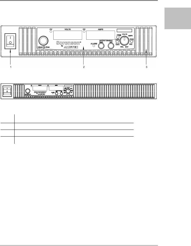
Introduction
Front Panel
1
Figure 1-1 XG Front Panels (Half Rack, above; Full Rack, below; not to-scale)
Item Description
1Front panel power switch
2Front panel display see Figure 1-2
3Air Intake Vents
M370430-01 Rev E |
1-5 |
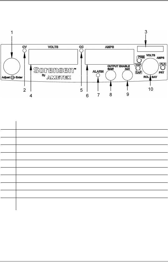
Introduction
Front Panel Display and Controls
Figure 1-2 Front Panel Display and Controls
Item Description
1Rotary Adjust/Enter control
2Constant Voltage (CV) Mode LED (green)
3Model Identification Label
4Output Voltage Display
5Constant Current (CC) Mode LED (green)
6Output Current Display
7Alarm Indicator LED (red)
8OUTPUT ENABLE Main button
9OUTPUT ENABLE Aux button
109-Position Mode Control (For detailed information, see “ Configuring Settings from the Front Panel” on page 3-2).
1-6 |
M370430-01 Rev E |

Introduction
Rear Panel Connectors on 850 Watt Models
1
Figure 1-3 XG 850 Watt Units: 6 V to 40 V Models
Figure 1-4 XG 850 Watt Units: 60 V to 150 V Models
Figure 1-5 XG 850 Watt Units: 300 V to 600 V Models
M370430-01 Rev E |
1-7 |

Introduction
Item Description
16 V– 40 V Models: DC Output Terminal Positive
60 V–150 V Models: DC Output Connectors Positive (6 .5 mm hole diameter) 300 V–600 V Models: DC Output Connectors Positive ( 6.5 mm hole diameter)
26 V– 40 V Models: DC Output Terminal Negative
60 V–150 V Models: DC Output Connectors Negative (6 .5 mm hole diameter) 300 V–600 V Models: DC Output Connectors Negative ( 6.5 mm hole diameter)
3 (J2) |
Ethernet (ENET) or GPIB Connector (optional) |
|
|
4 (J4) |
RS-232/RS-485 Connector In Port |
|
|
5 |
AC Input Connector (IEC Type) |
|
|
6 |
Chassis Ground Stud |
|
|
7 (J1) |
Analog Programming (APG) Connector. For pin information, see page 4-5. |
|
|
8 (J3) |
AUX Output and Isolated Analog Programming (ISOL) Connector. For pin information, see |
|
page 4-20. |
9 (J5) |
USB Connector |
|
|
10 (J6) |
RS-485 Connector Multichannel Port |
|
|
11 |
Ethernet/LAN (option) Connector |
|
|
12 |
Fan Exhaust Vents |
1-8 |
M370430-01 Rev E |
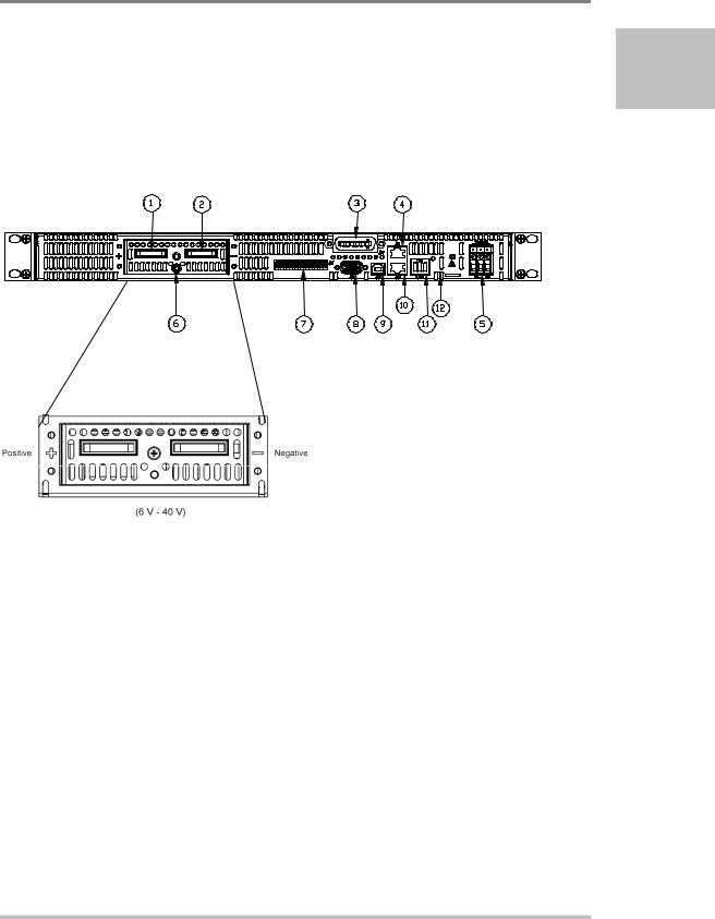
Introduction
Rear Panel Connectors on 1500 and 1700 Watt
Models
1
Figure 1-6 XG 1500 and 1700 Watt Units: 6 V to 40 V Models
M370430-01 Rev E |
1-9 |
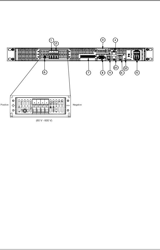
Introduction
|
|
Figure 1-7 XG 1500 and 1700 Watt Units: 60 V to 600 V Models |
Item |
|
Description |
|
||
|
|
|
1 |
|
6 V– 40 V Models: DC Output Terminal Positive (8.5 mm hole diameter) |
|
|
60 V–600 V Models: DC Output Connectors Positive |
2 |
|
6 V– 40 V Models: DC Output Terminal Negative (8.5 mm hole diameter) |
|
|
60 V–600 V Models: DC Output Connectors Negative |
3 (J2) |
|
Ethernet (ENET) or GPIB Connector (optional) |
|
|
|
4 (J4) |
|
RS-232/RS-485 Connector In Port |
|
|
|
5 |
|
AC Input Terminal |
|
|
|
6 |
|
Chassis Ground Stud |
|
|
|
7 (J1) |
|
Analog Programming (APG) Connector. For pin information, see page 4–5. |
|
|
|
8 (J3) |
|
AUX Output and Isolated Analog Programming (ISOL) Connector. For pin information, see |
|
|
page 4–20. |
9 (J5) |
|
USB Connector |
|
|
|
10 (J6) |
|
RS-485 Connector Multichannel Port |
|
|
|
11 |
|
Ethernet Connector |
|
|
|
12 |
|
Fan Exhaust Vents |
|
|
|
1-10 |
M370430-01 Rev E |
 Loading...